EP4530397A1 - Dispositif d'alimentation en courant gazeux d'un outil de formage de pieces moulees, outil equipe d'un tel dispositif et procede de commande de l'alimentation en courant gazeux - Google Patents
Dispositif d'alimentation en courant gazeux d'un outil de formage de pieces moulees, outil equipe d'un tel dispositif et procede de commande de l'alimentation en courant gazeux Download PDFInfo
- Publication number
- EP4530397A1 EP4530397A1 EP24201898.4A EP24201898A EP4530397A1 EP 4530397 A1 EP4530397 A1 EP 4530397A1 EP 24201898 A EP24201898 A EP 24201898A EP 4530397 A1 EP4530397 A1 EP 4530397A1
- Authority
- EP
- European Patent Office
- Prior art keywords
- tool
- channels
- channel
- gas stream
- forming
- Prior art date
- Legal status (The legal status is an assumption and is not a legal conclusion. Google has not performed a legal analysis and makes no representation as to the accuracy of the status listed.)
- Pending
Links
Images


Classifications
-
- D—TEXTILES; PAPER
- D21—PAPER-MAKING; PRODUCTION OF CELLULOSE
- D21J—FIBREBOARD; MANUFACTURE OF ARTICLES FROM CELLULOSIC FIBROUS SUSPENSIONS OR FROM PAPIER-MACHE
- D21J7/00—Manufacture of hollow articles from fibre suspensions or papier-mâché by deposition of fibres in or on a wire-net mould
-
- D—TEXTILES; PAPER
- D21—PAPER-MAKING; PRODUCTION OF CELLULOSE
- D21J—FIBREBOARD; MANUFACTURE OF ARTICLES FROM CELLULOSIC FIBROUS SUSPENSIONS OR FROM PAPIER-MACHE
- D21J3/00—Manufacture of articles by pressing wet fibre pulp, or papier-mâché, between moulds
Definitions
- a device for supplying a gas stream to a tool for forming molded parts from a fibrous material, wherein steam generated during forming can be discharged from the molded parts pressed in the tool via channels in the tool, a tool with such a device and a method for controlling the supply of a gas stream into a tool are described.
- Fibrous materials are increasingly being used to produce packaging for food (e.g., trays, capsules, boxes, etc.) and consumer goods (e.g., electronic devices, etc.), as well as beverage containers. Everyday items such as disposable cutlery and tableware are also made from fibrous materials. Fibrous materials include natural fibers and synthetic fibers. Recently, there has been an increasing use of fibrous materials that contain natural fibers or consist of fibers that can be obtained, for example, from renewable raw materials or waste paper. The natural fibers are mixed with water and, if necessary, other additives, such as starch, in a so-called pulp. Additives can also affect the color, barrier properties, and mechanical properties. This pulp can contain, for example, 0.1 to 10% by weight of natural fibers. The proportion of natural fibers varies depending on the process used to produce packaging, etc., and the product properties of the product to be manufactured.
- a fiber processing facility has several stations or Forming stations.
- fibers can be sucked into a cavity of a suction tool, whereby a preform is shaped or formed.
- the pulp is provided in a pulp supply and the suction tool, with at least one suction cavity whose geometry essentially corresponds to the product to be manufactured, is at least partially immersed in the pulp.
- suction takes place via openings in the suction cavity, which are connected to a corresponding suction device, with fibers from the pulp collecting on the surface of the suction cavity.
- the sucked-in fibers or a preform can then be brought via the suction tool into a pre-pressing tool, whereby the preform is pre-pressed.
- a pre-pressing tool for this purpose, elastic moldings can be used, for example, which are inflated for pressing and thereby exert pressure on the preforms.
- preforms can be prepared by scooping, whereby a scooping tool is immersed in the pulp and, when raised, fibers are deposited on parts of the scooping tool.
- the preforms are then pressed into finished molded parts in a hot-pressing device.
- Preforms are inserted into a hot-pressing tool, which may have a heated lower and upper tool half. Within the hot-pressing tool, the preforms are pressed between molding devices in cavities under heat input. The pressure and heat remove residual moisture, reducing the moisture content of the preforms from approximately 60% by weight before hot-pressing to, for example, 5-10% by weight after hot-pressing. The water vapor produced during hot-pressing is extracted through openings in the cavities and channels in the hot-pressing tool.
- a manufacturing process and a fiber processing device for this purpose are, for example, DE 10 2019 127 562 A1 known.
- the objective is to provide a solution that provides a uniform temperature distribution in a ventilated mold. Furthermore, the objective is to resolve the problems of the state of the art and provide an alternative to known molds.
- a device for supplying a gas stream to a tool for forming molded parts from a fibrous material wherein steam generated during forming can be discharged from the molded parts pressed in the tool via channels in the tool, comprising first channels in a tool body of the tool in the region of forming devices for forming molded parts and at least one second channel which is connected to the first channels and surrounds the regions in the tool body with the first channels, wherein the diameter of the at least one second channel is greater than the diameter of the first channels.
- the device achieves targeted guidance and subdivision of the guided gas flow or steam, whereby a main gas flow and secondary gas flows or main and secondary steam flows are generated in and around the tool.
- the first channels run within a tool body and are connected to the molding devices located above or below it via openings and, if necessary, further channels.
- the first channels extend within the tool body parallel to the molding surface on which the molding devices are arranged or provided.
- Such a tool body has regions located below or above the molding devices and assigned to them. When steam is extracted, water enters these regions. During a hot-pressing process, steam is the first to be released.
- the venting occurs according to the position of the supply point and the design of the first channels, as well as the number and size of the molding device and the shape of the tool body. Since the supply is usually made at one side/location in the prior art, an uneven supply occurs, so that the water vapor in the tool body is dissipated at different rates through the first channels. Some areas are vented quickly and thus tend to cool down rapidly, while in other areas the hot water vapor "stands" or lingers for a relatively long time, so that no cooling occurs.
- the additionally supplied gas stream can be introduced, for example, on two or three sides of a tool block, so that venting is more evenly achieved. If the residence time of water vapor discharged from the cavities or molding devices as well as the flow rate are determined in advance, the supply of a gas stream from the second channel into individual channels can also be specifically controlled in such a way that the entire flow rate is optimized with regard to a uniform temperature distribution.
- the at least one second channel is designed such that it has a larger cross-section than the first channels, whereby a flow through the first channels via a gas stream supplied through the at least one second channel is regulated in a first step.
- the device thus enables the subdivision of the main/secondary gas flows or steam flows by adjusting and selecting flow cross-sections, as well as by narrowing or widening them.
- Gas flows include both gas mixtures (e.g., air) and gases.
- the subdivision of the channels in the tool and the device also means that the steam generated, including the thermal energy stored therein, can remain in specific places without a significant increase in pressure, and the reduced flow at these points reduces the (unnecessary energy dissipation).
- the steam can escape from the molding devices or cavities into the periphery (tool body, base, basic structure, pipe system, hose system) without pressure or almost without pressure, whereby the steam flow is imposed on an existing air or gas flow.
- a tool e.g., a hot-pressing tool for producing molded parts from a fiber-containing material.
- This can increase the efficiency of a hot-pressing process, increase process stability, and improve the product quality of the hot-pressed molded parts.
- the local cooling of molding devices and/or a tool body of the tool can be taken into account. This cooling occurs when water escaping from preforms evaporates due to the thermal energy extracted from the tool or the molding devices.
- a tool body in particular can be kept at an essentially constant temperature during the hot-pressing process, especially over several cycles. This has a further positive effect on the aforementioned advantages.
- the first channels can be interconnected at least in the areas of molding devices, so that the ventilation or flow through for targeted steam removal is improved.
- the at least one second channel can collectively surround all areas of the molding devices of a tool body.
- the at least one second channel runs around a tool body and thus surrounds it on four sides in the case of a rectangular tool body.
- the at least one second channel serves not only as a channel for the collective supply of an additional gas stream but also for the removal of a saturated gas stream, wherein the saturated gas stream has absorbed water vapor from the areas of the molding devices.
- the connecting points between the first channels and the at least one second channel can have a smaller diameter than the first channels.
- the connecting points act as throttle elements and significantly influence the amount of gas flowing into the respective first channel.
- Connection points can be designed differently for the first channels in order to achieve the necessary flow to achieve a uniform temperature distribution.
- the opening width of connecting points between the first channels and the at least one second channel can be adjustable in order to be able to make adjustments, for example, during a tool change to produce different molded parts, wherein the mold devices connected to a tool body are exchanged. During such a tool change, the areas of the mold devices can change. In addition, other mold device-specific features influence the amount of steam that enters the first channels.
- the adaptability and changeability of the opening width thus makes it possible to take a tool change into account and also to make adjustments during tool operation if, for example, changes are detected in the finished molded parts and/or in the discharged saturated gas stream. For this purpose, a change can be detected, for example, via a control system and corresponding detection devices (camera, sensors, etc.).
- the control system can therefore, for example, actuate throttle valves accordingly to change the opening width.
- a camera can, for example, record the surface of the molded parts after hot pressing. Moist areas can thus be visually detected. Based on the position of each molded part, a direct conclusion can be drawn about the corresponding first channels or the respective area of the molding system, and the corresponding throttle valves for these channels can be controlled.
- Machine learning can also be integrated, for example, by conducting a test run and obtaining reference data for the control system.
- the at least one second channel can be divided into channel sections, and the supply of a gas flow into the channel sections can be regulated. This allows the amount of gas flow primarily available and supplied to the first channels to be further controlled in order to achieve a uniform temperature distribution in the mold.
- the supply of a gas stream into the at least one second channel and/or the first channels can be controlled by throttle elements and/or conveying devices.
- Throttle elements can be, for example, valves or throttle flaps.
- Conveying devices can be, for example, pumps or fans, which are integrated into and/or connected to the second channel.
- the flow through the tool and the supply of an additional gas flow can also be controlled via a suction or negative pressure prevailing in a discharge line for saturated gas flow.
- Conveying devices for example, can be used for this purpose.
- the device can comprise at least one device for controlling the temperature of a gas stream that can be fed into the at least one second channel and/or the first channels in order to influence the temperature of the supplied gas stream. For example, heating can occur, since warmer air, for example, can experience a higher water saturation, allowing more vapor to be removed.
- the first channels may comprise a number of channels extending orthogonally to one another.
- the at least one second channel has large cross-sections around the tool and cross-sectional constrictions in transverse and longitudinal channels (first channels) in a tool body.
- Such a device can, for example, be attached to a tool with existing first channels for flow through or be provided as an integral component of a tool.
- a tool for forming molded parts from a fibrous material wherein steam generated during forming can be discharged from the molded parts pressed in the tool via channels in the tool, comprising first channels in a tool body of the tool in the region of forming devices for forming molded parts and at least one device according to one of the above embodiments, wherein the at least one device has at least one second channel which is connected to the first channels and surrounds the regions in the tool body with the first channels.
- a main gas flow integrated in the tool is directed in and around the tool by a targeted arrangement of channels and their cross sections in such a way that a flowing, cold or preheated, preferably dry, draft gas flow creates a hot Despite uniform ventilation, the tool body is not cooled asymmetrically and thus creates a uniform temperature pattern on the cavities or mold devices.
- the above-mentioned object is further achieved by a method for controlling the supply of a gas stream into a tool for forming molded parts from a fibrous material, wherein steam generated during forming is discharged from the molded parts pressed in the tool via channels in the tool, wherein the tool has first channels in a tool body of the tool in the region of molding devices for forming molded parts and at least one device according to one of the above embodiments is provided, wherein the at least one device has at least one second channel which is connected to the first channels and surrounds the regions in the tool body with the first channels, wherein the supply of a gas stream into the at least one second channel and/or the first channels is controllable via at least one throttle device and/or a conveying device.
- the supplied gas/air or steam flow is directed into technically advantageous paths, since main and secondary channels are provided in the tool body of the tool, onto which the resulting steam can "jump" without pressure and according to the amount produced.
- the steam flow is specifically influenced and directed by secondary channels with cross-sectional constrictions and expansions (bore diameters, blind plugs, etc.), allowing steam accumulation zones to form symmetrically on the tool.
- the resulting energy "lingers" in these zones for statistically longer or deliberately shorter periods to achieve a consistent temperature pattern or even temperature distribution.
- the solution proposed here enables the conversion of a state-of-the-art asymmetric cooling to a symmetric influence by targeted steering of the steam/draft gas flow.
- Fig. 1 shows a schematic representation of a fiber processing device 1000 for producing three-dimensional molded parts 3000 from a fiber-containing material.
- the fiber-containing material for producing molded parts 3000 is processed in a pulp tank 200 of the fiber processing device 1000.
- water and fiber materials, as well as If necessary, additives are introduced into a pulp tank 200 and the pulp is processed in the pulp tank 200 by mixing the individual components with the introduction of heat and aids such as a stirrer.
- Pulp is an aqueous solution containing fibers.
- the fiber content of the aqueous solution can range from 0.1 to 10% by weight. It can also contain additives and additives, such as starch, chemical additives, wax, etc.
- the fibers can be, for example, natural fibers, such as cellulose fibers, or fibers from a fibrous source material (e.g., waste paper).
- a fiber processing plant offers the possibility of processing pulp in large quantities and making it available to several fiber processing facilities.
- the fiber processing device 1000 can be used to produce, for example, biodegradable molded parts 3000, such as cups, capsules, bowls, plates, and other molded and/or packaging parts (e.g., as holder/support structures for electronic devices). Since the raw material for these products is a fibrous pulp with natural fibers, the products produced in this way can themselves be used as raw materials for the production of similar products after use or can be composted, as they are generally completely decomposable and do not contain any harmful, environmentally hazardous substances.
- biodegradable molded parts 3000 such as cups, capsules, bowls, plates, and other molded and/or packaging parts (e.g., as holder/support structures for electronic devices). Since the raw material for these products is a fibrous pulp with natural fibers, the products produced in this way can themselves be used as raw materials for the production of similar products after use or can be composted, as they are generally completely decomposable and do not contain any harmful, environmentally hazardous substances.
- the fiber processing device 1000 shown has a frame 100, which can be surrounded by a casing.
- the supply units 300 of the fiber processing device 1000 include, for example, interfaces for the supply of media (e.g., water, pulp, compressed air, gas, etc.) and energy (power supply), a central control unit 310, at least one suction device 320 (e.g., comprising a vacuum tank and/or fan), line systems for the various media, pumps, valves, lines, sensors, measuring devices, a BUS system, etc., as well as interfaces for bidirectional communication via a wired and/or wireless data connection. Instead of a wired data connection, a data connection via a fiber optic cable can also exist.
- the data connection can exist, for example, between the control unit 310 and a central controller for several fiber processing devices 1000, to a fiber processing plant, to a service center, and/or other devices. It can be connected via a bidirectional Data connection also allows control of the fiber processing device 1000 via a mobile device, such as a smartphone, tablet computer or the like.
- the control unit 310 is in bidirectional communication with an HMI panel 700 via a BUS system or a data connection.
- the HMI (Human-Machine Interface) panel 700 has a display that shows operating data and states of the fiber processing device 1000 for selectable components or the entire fiber processing device 1000.
- the display can be designed as a touch display, so that settings can be made manually by an operator of the fiber processing device 1000. Additionally or alternatively, further input means, such as a keyboard, a joystick, a keypad, etc., can be provided on the HMI panel 700 for operator inputs. Settings can be changed and the operation of the fiber processing device 1000 can be influenced via these.
- the fiber processing device 1000 has a robot 500.
- the robot 500 is designed as a so-called 6-axis robot and is thus capable of picking up parts, rotating them, and moving them in all spatial directions within its operating radius.
- other handling devices can also be provided that are designed to pick up products (preforms, molded parts) and twist them or rotate them and move them in various spatial directions.
- such a handling device can also be designed differently, whereby the arrangement of the corresponding stations of the fiber processing device 1000 can deviate from the illustrated embodiment.
- a suction tool 520 is arranged on the robot 500.
- the suction tool 520 has cavities formed as a negative of the three-dimensional molded parts 3000 to be formed, serving as suction cavities.
- the cavities can, for example, have a net-like surface to which fibers from the pulp adhere during suction. Behind the net-like surfaces, the cavities are connected to a suction device via channels in the suction tool 520.
- the suction device can, for example, be realized by a suction device 320. Pulp can be sucked in via the suction device when the suction tool 520 is thus located within the pulp basin. 200, the cavities are at least partially located in the aqueous fiber solution, the pulp.
- a vacuum or negative pressure for sucking in fibers when the suction tool 520 is located in the pulp basin 200 and the pulp can be provided via the suction device 320.
- the fiber processing device 1000 has corresponding means in the supply units 300.
- the suction tool 520 has lines for providing the vacuum/negative pressure from the suction device 320 in the supply units 300 to the suction tool 520 and the openings in the cavities. Valves are arranged in the lines, which can be controlled via the control unit 310 and thus regulate the suction of the fibers.
- the suction device 320 can also "blow out" fibers, for which purpose the suction device 320 is switched to a different operating mode depending on its design.
- the suction tool 520 is immersed in the pulp and a negative pressure/vacuum is applied to the openings of the cavities so that fibers are sucked out of the pulp and, for example, adhere to the network of cavities of the suction tool 520.
- the robot 500 then lifts the suction tool 520 from the pulp tank 200 and moves it, along with the fibers adhering to the cavities, which still have a relatively high moisture content of, for example, over 80% by weight of water, to a pre-pressing station 400 of the fiber processing device 1000, wherein the negative pressure in the cavities is maintained for transfer.
- the pre-pressing station 400 has a pre-pressing tool with pre-pressing molds.
- the pre-pressing molds can, for example, be designed as positives of the molded parts 3000 to be produced and, in order to accommodate the fibers adhering in the cavities, have a size appropriate to the shape of the molded parts 3000.
- the suction tool 520 with the fibers adhering to the cavities is moved to the pre-pressing station 400 so that the fibers are pressed into the cavities.
- the fibers are pressed together in the cavities, thus creating a stronger bond between the fibers.
- the moisture content of the preforms formed from the sucked-in fibers is reduced, so that the preforms formed after pre-pressing only have a A moisture content of, for example, 60% by weight can be achieved.
- Flexible pre-press molds can be used to press out the water. These molds are inflated, for example, using compressed air (process air), thereby pressing the fibers against the wall of a cavity in another suction tool part. This "inflating" process not only presses out the water, but also reduces the thickness of the absorbed fiber layer.
- liquid or pulp can be sucked out and returned via the suction tool 520 and/or via further openings in pre-press molds or tool parts (cavities).
- the preforms thus produced are moved on the suction tool 520 via the robot 500 to a hot-pressing station 600.
- the negative pressure is maintained on the suction tool 520 so that the preforms remain in the cavities.
- the preforms are transferred via the suction tool 520 to a lower tool body 620, which can be moved along the production line from the hot-pressing device 610.
- the suction tool 520 is moved to the lower tool body 620 so that the preforms can be placed on mold devices 624 of the lower tool body 620.
- overpressure is generated via the openings in the suction tool 520, so that the preforms are actively deposited from the cavities, or the suction is terminated, so that the preforms remain on the mold devices 624 of the lower tool body 620 due to gravity.
- overpressure is generated via the openings in the suction tool 520, so that the preforms are actively deposited from the cavities, or the suction is terminated, so that the preforms remain on the mold devices 624 of the lower tool body 620 due to gravity.
- the suction tool 520 is moved away over the robot 500 and the suction tool 520 is immersed into the pulp tank 200 in order to suck in further fibers for the production of molded parts 3000 from fibrous material.
- the lower tool body 620 moves into the hot-pressing station 600.
- the preforms are pressed into finished molded parts 3000 under heat input and high pressure, for which purpose an upper tool body 630 is brought onto the lower tool body 620 via a press.
- the upper tool body 630 has cavities (molding devices) corresponding to the molding devices 624.
- the molding devices 624 can be connected to the tool bodies 620, 630 (e.g., screwed) or installed integrally. In the illustrated embodiments, the molding devices 624 are screwed to the tool bodies 620, 630.
- the lower tool body 620 and the upper tool body 630 are moved away from one another, and the upper tool body 630 is moved along the fiber processing device 1000 in the production direction.
- the finished molded parts 3000 are sucked in via the upper tool body 630 and thus remain within the cavities.
- the finished molded parts 3000 are removed from the hot-pressing station 600 and, after being moved, are deposited on a conveyor belt of a conveyor device 800 via the upper tool body 630.
- the suction via the upper tool body 630 is terminated, and the molded parts 3000 remain on the conveyor belt.
- the upper tool body 630 moves back to the hot-pressing station 600, and another hot-pressing process can be performed.
- the lower tool body 620 can be moved in an opposite direction before extending to receive the preforms in order to remove the finished products/molded parts 3000 from the hot-pressing device for further transport.
- a hot-pressing device 610 can also be loaded with preforms in other ways, whereby no lateral movement of the tool bodies 620, 630 is necessary.
- the fiber processing device 1000 further comprises a conveyor device 800 with a conveyor belt.
- the manufactured molded parts 3000 made of fibrous material can be placed on the conveyor belt after the final molding and hot pressing in the hot-pressing station 600 and removed from the fiber processing device 1000.
- further processing can take place, such as filling and/or stacking the manufactured products. Stacking can be performed, for example, via an additional robot or another device.
- the fiber processing device 1000 from Fig. 1 shows a possible embodiment.
- a fiber processing device according to the technical teaching described herein also have only one forming station with an exchangeable tool, for example a suction tool 520 or a hot-pressing tool, in which fiber-containing material can be processed, wherein different tools for producing different three-dimensional molded parts 3000 can be accommodated in the at least one forming station.
- the further for the fiber processing device 1000 of Fig. 1 The stations and devices shown are not absolutely necessary for the implementation of the technical teaching.
- the tool bodies 620, 630 are heated by heating elements and thus brought to the required temperature. During hot pressing, the water contained in the relatively moist preforms evaporates. This hot steam is discharged via openings and channels in the molding devices 624.
- the tool bodies 620, 630 have corresponding channels that are connected to the openings.
- the tool bodies 620, 630 have secondary channels 622 (first channels) that run through the tool bodies 620, 630 and are connected to the openings and channels in the molding devices 624.
- a first group of parallel secondary channels 622 runs orthogonally to a second group of parallel secondary channels 622, wherein the secondary channels 622 of the first group and the second group intersect and are connected to one another at the interfaces.
- Fig. 2 shows a schematic perspective view of tool bodies 620, 630 of a hot pressing device 610.
- the hot pressing station 610 has four mold devices 624 and corresponding cavities on the opposite tool bodies 620, 630.
- 624 molded parts 3000 are placed on the four molding devices.
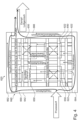
- Fig. 3 shows a schematic plan view of the lower tool body 620 of Fig. 2 , wherein the molding device 624 is shown in the lower right area without a molded part 3000.
- a hot-pressing device 610 the water vapor escaping from the hot surfaces of the moist preforms during the hot-pressing process is extracted.
- a gas stream such as process air, is introduced into the secondary channels, which is preferably heated (via additional heating devices or heat exchangers).
- a device 640 which has a main channel 642 (second channel) surrounding the tool body 620.
- the main channel 642 has a larger diameter than the secondary channels 622.
- the ratio of the main channel 642 to the secondary channel (622) diameter can be 1:0.1 - 0.8.
- Fig. 4 shows a schematic representation of a tool body 620 with a device 640 for supplying a gas stream.
- the main channel 642 has four channel sections 660, 662, 664, 666.
- the flow of the process air stream introduced via the main channel 642 is determined such that an optimal flow is achieved to achieve an optimal, uniform temperature distribution.
- Fig. 5 For example, a temperature distribution in the tool body 620 is shown, with the temperature being highest in areas 650 in particular and essentially the same in all four areas 650 and thus also in the forming devices 624.
- the steam exits in all directions in the areas 650 and is distributed in the areas 650, the channel sections of the secondary channels which are assigned to the forming devices 624.
- process air can be supplied and discharged in the four duct sections 660, 662, 664, 666, as shown in Fig. 4 shown schematically.
- the steam-air mixture saturated gas stream
- further treatment e.g., heat exchanger
- connection points between the main channel 642 and the secondary channels 622 are designed in such a way that the Fig. 5
- the temperature distribution shown is established.
- Controllable throttle elements flaps, valves
- These can be used to adjust the temperature during operation and/or to change the temperature when changing the tool.
- the flow conditions can be specifically directed to ensure uniform temperature distribution.
Landscapes
- Engineering & Computer Science (AREA)
- Manufacturing & Machinery (AREA)
- Dry Formation Of Fiberboard And The Like (AREA)
Applications Claiming Priority (1)
| Application Number | Priority Date | Filing Date | Title |
|---|---|---|---|
| DE102023126173.8A DE102023126173A1 (de) | 2023-09-26 | 2023-09-26 | Einrichtung zur Zufuhr eines Gasstroms einem Werkzeug zum Formen von Formteilen, Werkzeug mit einer solchen Einrichtung und Verfahren zur Steuerung der Zufuhr eines Gasstroms |
Publications (1)
| Publication Number | Publication Date |
|---|---|
| EP4530397A1 true EP4530397A1 (fr) | 2025-04-02 |
Family
ID=92895620
Family Applications (1)
| Application Number | Title | Priority Date | Filing Date |
|---|---|---|---|
| EP24201898.4A Pending EP4530397A1 (fr) | 2023-09-26 | 2024-09-23 | Dispositif d'alimentation en courant gazeux d'un outil de formage de pieces moulees, outil equipe d'un tel dispositif et procede de commande de l'alimentation en courant gazeux |
Country Status (3)
| Country | Link |
|---|---|
| US (1) | US20250101686A1 (fr) |
| EP (1) | EP4530397A1 (fr) |
| DE (1) | DE102023126173A1 (fr) |
Citations (2)
| Publication number | Priority date | Publication date | Assignee | Title |
|---|---|---|---|---|
| CN2477694Y (zh) * | 2001-01-07 | 2002-02-20 | 浙江衢州绿色餐具有限公司 | 纸浆模塑蒸气电加热模具 |
| DE102019127562A1 (de) | 2019-10-14 | 2021-04-15 | Kiefel Gmbh | Faserformanlage zur herstellung von formteilen aus umweltverträglich abbaubarem fasermaterial |
Family Cites Families (3)
| Publication number | Priority date | Publication date | Assignee | Title |
|---|---|---|---|---|
| US3147180A (en) * | 1960-12-23 | 1964-09-01 | Gen Fibre Company | Automatic molding apparatus for forming pulp articles |
| JP2836801B2 (ja) * | 1992-03-06 | 1998-12-14 | 日本碍子株式会社 | 繊維成形物の抄造型、抄造方法及び抄造装置、並びに抄造された繊維成形物 |
| DE102022108094A1 (de) * | 2022-04-05 | 2023-10-05 | Kiefel Gmbh | Heisspress-werkzeughälfte, heisspresseinrichtung mit einem heisspresswerkzeug und verfahren zum heisspressen von vorformlingen aus einem faserhaltigen material |
-
2023
- 2023-09-26 DE DE102023126173.8A patent/DE102023126173A1/de active Granted
-
2024
- 2024-09-18 US US18/888,481 patent/US20250101686A1/en active Pending
- 2024-09-23 EP EP24201898.4A patent/EP4530397A1/fr active Pending
Patent Citations (2)
| Publication number | Priority date | Publication date | Assignee | Title |
|---|---|---|---|---|
| CN2477694Y (zh) * | 2001-01-07 | 2002-02-20 | 浙江衢州绿色餐具有限公司 | 纸浆模塑蒸气电加热模具 |
| DE102019127562A1 (de) | 2019-10-14 | 2021-04-15 | Kiefel Gmbh | Faserformanlage zur herstellung von formteilen aus umweltverträglich abbaubarem fasermaterial |
Also Published As
| Publication number | Publication date |
|---|---|
| DE102023126173A1 (de) | 2025-03-27 |
| US20250101686A1 (en) | 2025-03-27 |
Similar Documents
| Publication | Publication Date | Title |
|---|---|---|
| EP4257349B1 (fr) | Procédé de régulation d'un dispositif de pressage à chaud, composant d'outil pour dispositif de pressage à chaud et dispositif de pressage à chaud | |
| DE102022108094A1 (de) | Heisspress-werkzeughälfte, heisspresseinrichtung mit einem heisspresswerkzeug und verfahren zum heisspressen von vorformlingen aus einem faserhaltigen material | |
| DE202023105782U1 (de) | Formkörper für ein Vorpresswerkzeug und Vorpresswerkzeug | |
| DE102022111908A1 (de) | Formeinrichtung zum formen von erzeugnissen aus faserhaltigem material, faserformanlage, verfahren zum formen von erzeugnissen aus faserhaltigem material und erzeugnis aus faserhaltigem material | |
| EP4101981B1 (fr) | Station de formage, installation de moulage de fibres et procédé de fabrication de pièces moulées à partir de matière fibreuse | |
| DE102019127559A1 (de) | Faserformanlage zur herstellung von formteilen aus umweltverträglich abbaubarem fasermaterial | |
| EP4530397A1 (fr) | Dispositif d'alimentation en courant gazeux d'un outil de formage de pieces moulees, outil equipe d'un tel dispositif et procede de commande de l'alimentation en courant gazeux | |
| EP4675042A1 (fr) | Corps moulé pour un outil de presse de pressage pour le pressage de préformes tridimensionnelles à partir d'un matériau fibreux et poste de presse | |
| EP4464841A2 (fr) | Procédé d'aspiration de fibres à partir d'une pâte à papier à l'aide d'un dispositif d'aspiration et dispositif d'aspiration | |
| DE102023106953A1 (de) | Formwerkzeug zur Herstellung von Formteilen und Verfahren zur Herstellung von Formteilen unter Verwendung eines Formwerkzeugs | |
| EP4345209A1 (fr) | Moule et procédé de régulation de la répartition de température dans un moule pour produits tridimensionnels | |
| DE69207796T2 (de) | Strangpressen mit einer Vorrichtung zum Beschichten wenigstens zweier Kerne mit einem gleichartigen Werkstoff und Beschichtungsverfahren | |
| DE102021126785A1 (de) | Transportvorrichtung für eine Produktionslinie für ein geformtes Faserprodukt | |
| DE2852406A1 (de) | Vorrichtung zur herstellung von hohlglasartikeln | |
| DE102022120414A1 (de) | Faserverarbeitungseinrichtung mit einer ausrichtungseinheit zur verlagerung und positionierung von fasern und verfahren zum betreiben einer faserverarbeitungseinrichtung | |
| DE102009014090B4 (de) | Verpackungsmaschine und Verpackungsverfahren mit Wiederverwendung von Druckluft | |
| DE102008008630B3 (de) | Absetzplattenanordnung | |
| DE102022125886A1 (de) | Verfahren zur herstellung von dreidimensionalen formteilen aus einem faserhaltigen material und faserverarbeitungseinrichtung | |
| DE102023112876A1 (de) | Einrichtung und Verfahren zum Erwärmen von Prozessmedien in einem Faserverarbeitungsprozess | |
| DE19655149C2 (de) | Verfahren zur Herstellung trockengepreßter Formlinge | |
| DE102023112887A1 (de) | Verfahren zum Betreiben mindestens einer Einrichtung für die Verarbeitung von faserhaltigem Material zur Herstellung von dreidimensionalen Formteilen und Einrichtung dazu | |
| DE102017130128A1 (de) | Vorrichtung und Verfahren zur Herstellung einer Matte aus Material auf einem Transportband sowie Anlage zum Verpressen einer solchen Matte | |
| EP0655315B1 (fr) | Procédé de commande de pression pour moulage par pression d'air d'un article à partir d'une feuille de matière plastique et dispositif pour sa mise en oeuvre | |
| DE202023105781U1 (de) | Formkörper für ein Vorpresswerkzeug und Vorpresswerkzeug | |
| DE202023105783U1 (de) | Formkörper für ein Vorpresswerkzeug und Vorpresswerkzeug |
Legal Events
| Date | Code | Title | Description |
|---|---|---|---|
| PUAI | Public reference made under article 153(3) epc to a published international application that has entered the european phase |
Free format text: ORIGINAL CODE: 0009012 |
|
| STAA | Information on the status of an ep patent application or granted ep patent |
Free format text: STATUS: THE APPLICATION HAS BEEN PUBLISHED |
|
| AK | Designated contracting states |
Kind code of ref document: A1 Designated state(s): AL AT BE BG CH CY CZ DE DK EE ES FI FR GB GR HR HU IE IS IT LI LT LU LV MC ME MK MT NL NO PL PT RO RS SE SI SK SM TR |
|
| STAA | Information on the status of an ep patent application or granted ep patent |
Free format text: STATUS: REQUEST FOR EXAMINATION WAS MADE |
|
| 17P | Request for examination filed |
Effective date: 20250630 |