EP4530335A1 - Energy recovery during carbon dioxide capture in preform production process - Google Patents
Energy recovery during carbon dioxide capture in preform production process Download PDFInfo
- Publication number
- EP4530335A1 EP4530335A1 EP24203342.1A EP24203342A EP4530335A1 EP 4530335 A1 EP4530335 A1 EP 4530335A1 EP 24203342 A EP24203342 A EP 24203342A EP 4530335 A1 EP4530335 A1 EP 4530335A1
- Authority
- EP
- European Patent Office
- Prior art keywords
- heat
- steam
- separator
- recovery unit
- various embodiments
- Prior art date
- Legal status (The legal status is an assumption and is not a legal conclusion. Google has not performed a legal analysis and makes no representation as to the accuracy of the status listed.)
- Pending
Links
Images


Classifications
-
- C—CHEMISTRY; METALLURGY
- C10—PETROLEUM, GAS OR COKE INDUSTRIES; TECHNICAL GASES CONTAINING CARBON MONOXIDE; FUELS; LUBRICANTS; PEAT
- C10L—FUELS NOT OTHERWISE PROVIDED FOR; NATURAL GAS; SYNTHETIC NATURAL GAS OBTAINED BY PROCESSES NOT COVERED BY SUBCLASSES C10G OR C10K; LIQUIFIED PETROLEUM GAS; USE OF ADDITIVES TO FUELS OR FIRES; FIRE-LIGHTERS
- C10L3/00—Gaseous fuels; Natural gas; Synthetic natural gas obtained by processes not covered by subclass C10G, C10K; Liquefied petroleum gas
- C10L3/06—Natural gas; Synthetic natural gas obtained by processes not covered by C10G, C10K3/02 or C10K3/04
- C10L3/08—Production of synthetic natural gas
-
- B—PERFORMING OPERATIONS; TRANSPORTING
- B64—AIRCRAFT; AVIATION; COSMONAUTICS
- B64C—AEROPLANES; HELICOPTERS
- B64C25/00—Alighting gear
- B64C25/32—Alighting gear characterised by elements which contact the ground or similar surface
- B64C25/42—Arrangement or adaptation of brakes
- B64C25/423—Braking devices acting by reaction of gaseous medium
-
- B—PERFORMING OPERATIONS; TRANSPORTING
- B01—PHYSICAL OR CHEMICAL PROCESSES OR APPARATUS IN GENERAL
- B01D—SEPARATION
- B01D53/00—Separation of gases or vapours; Recovering vapours of volatile solvents from gases; Chemical or biological purification of waste gases, e.g. engine exhaust gases, smoke, fumes, flue gases, aerosols
- B01D53/34—Chemical or biological purification of waste gases
- B01D53/46—Removing components of defined structure
- B01D53/62—Carbon oxides
-
- B—PERFORMING OPERATIONS; TRANSPORTING
- B01—PHYSICAL OR CHEMICAL PROCESSES OR APPARATUS IN GENERAL
- B01D—SEPARATION
- B01D53/00—Separation of gases or vapours; Recovering vapours of volatile solvents from gases; Chemical or biological purification of waste gases, e.g. engine exhaust gases, smoke, fumes, flue gases, aerosols
- B01D53/34—Chemical or biological purification of waste gases
- B01D53/74—General processes for purification of waste gases; Apparatus or devices specially adapted therefor
- B01D53/76—Gas phase processes, e.g. by using aerosols
-
- C—CHEMISTRY; METALLURGY
- C04—CEMENTS; CONCRETE; ARTIFICIAL STONE; CERAMICS; REFRACTORIES
- C04B—LIME, MAGNESIA; SLAG; CEMENTS; COMPOSITIONS THEREOF, e.g. MORTARS, CONCRETE OR LIKE BUILDING MATERIALS; ARTIFICIAL STONE; CERAMICS; REFRACTORIES; TREATMENT OF NATURAL STONE
- C04B35/00—Shaped ceramic products characterised by their composition; Ceramics compositions; Processing powders of inorganic compounds preparatory to the manufacturing of ceramic products
- C04B35/622—Forming processes; Processing powders of inorganic compounds preparatory to the manufacturing of ceramic products
- C04B35/626—Preparing or treating the powders individually or as batches ; preparing or treating macroscopic reinforcing agents for ceramic products, e.g. fibres; mechanical aspects section B
- C04B35/62605—Treating the starting powders individually or as mixtures
- C04B35/62645—Thermal treatment of powders or mixtures thereof other than sintering
- C04B35/6267—Pyrolysis, carbonisation or auto-combustion reactions
-
- C—CHEMISTRY; METALLURGY
- C04—CEMENTS; CONCRETE; ARTIFICIAL STONE; CERAMICS; REFRACTORIES
- C04B—LIME, MAGNESIA; SLAG; CEMENTS; COMPOSITIONS THEREOF, e.g. MORTARS, CONCRETE OR LIKE BUILDING MATERIALS; ARTIFICIAL STONE; CERAMICS; REFRACTORIES; TREATMENT OF NATURAL STONE
- C04B35/00—Shaped ceramic products characterised by their composition; Ceramics compositions; Processing powders of inorganic compounds preparatory to the manufacturing of ceramic products
- C04B35/71—Ceramic products containing macroscopic reinforcing agents
- C04B35/78—Ceramic products containing macroscopic reinforcing agents containing non-metallic materials
- C04B35/80—Fibres, filaments, whiskers, platelets, or the like
-
- C—CHEMISTRY; METALLURGY
- C04—CEMENTS; CONCRETE; ARTIFICIAL STONE; CERAMICS; REFRACTORIES
- C04B—LIME, MAGNESIA; SLAG; CEMENTS; COMPOSITIONS THEREOF, e.g. MORTARS, CONCRETE OR LIKE BUILDING MATERIALS; ARTIFICIAL STONE; CERAMICS; REFRACTORIES; TREATMENT OF NATURAL STONE
- C04B35/00—Shaped ceramic products characterised by their composition; Ceramics compositions; Processing powders of inorganic compounds preparatory to the manufacturing of ceramic products
- C04B35/71—Ceramic products containing macroscopic reinforcing agents
- C04B35/78—Ceramic products containing macroscopic reinforcing agents containing non-metallic materials
- C04B35/80—Fibres, filaments, whiskers, platelets, or the like
- C04B35/83—Carbon fibres in a carbon matrix
-
- C—CHEMISTRY; METALLURGY
- C07—ORGANIC CHEMISTRY
- C07C—ACYCLIC OR CARBOCYCLIC COMPOUNDS
- C07C1/00—Preparation of hydrocarbons from one or more compounds, none of them being a hydrocarbon
- C07C1/02—Preparation of hydrocarbons from one or more compounds, none of them being a hydrocarbon from oxides of a carbon
- C07C1/12—Preparation of hydrocarbons from one or more compounds, none of them being a hydrocarbon from oxides of a carbon from carbon dioxide with hydrogen
-
- B—PERFORMING OPERATIONS; TRANSPORTING
- B01—PHYSICAL OR CHEMICAL PROCESSES OR APPARATUS IN GENERAL
- B01D—SEPARATION
- B01D2257/00—Components to be removed
- B01D2257/50—Carbon oxides
- B01D2257/504—Carbon dioxide
-
- C—CHEMISTRY; METALLURGY
- C04—CEMENTS; CONCRETE; ARTIFICIAL STONE; CERAMICS; REFRACTORIES
- C04B—LIME, MAGNESIA; SLAG; CEMENTS; COMPOSITIONS THEREOF, e.g. MORTARS, CONCRETE OR LIKE BUILDING MATERIALS; ARTIFICIAL STONE; CERAMICS; REFRACTORIES; TREATMENT OF NATURAL STONE
- C04B2235/00—Aspects relating to ceramic starting mixtures or sintered ceramic products
- C04B2235/02—Composition of constituents of the starting material or of secondary phases of the final product
- C04B2235/30—Constituents and secondary phases not being of a fibrous nature
- C04B2235/38—Non-oxide ceramic constituents or additives
- C04B2235/3817—Carbides
- C04B2235/3821—Boron carbides
-
- C—CHEMISTRY; METALLURGY
- C04—CEMENTS; CONCRETE; ARTIFICIAL STONE; CERAMICS; REFRACTORIES
- C04B—LIME, MAGNESIA; SLAG; CEMENTS; COMPOSITIONS THEREOF, e.g. MORTARS, CONCRETE OR LIKE BUILDING MATERIALS; ARTIFICIAL STONE; CERAMICS; REFRACTORIES; TREATMENT OF NATURAL STONE
- C04B2235/00—Aspects relating to ceramic starting mixtures or sintered ceramic products
- C04B2235/02—Composition of constituents of the starting material or of secondary phases of the final product
- C04B2235/50—Constituents or additives of the starting mixture chosen for their shape or used because of their shape or their physical appearance
- C04B2235/52—Constituents or additives characterised by their shapes
- C04B2235/5208—Fibers
- C04B2235/5212—Organic
-
- C—CHEMISTRY; METALLURGY
- C04—CEMENTS; CONCRETE; ARTIFICIAL STONE; CERAMICS; REFRACTORIES
- C04B—LIME, MAGNESIA; SLAG; CEMENTS; COMPOSITIONS THEREOF, e.g. MORTARS, CONCRETE OR LIKE BUILDING MATERIALS; ARTIFICIAL STONE; CERAMICS; REFRACTORIES; TREATMENT OF NATURAL STONE
- C04B2235/00—Aspects relating to ceramic starting mixtures or sintered ceramic products
- C04B2235/02—Composition of constituents of the starting material or of secondary phases of the final product
- C04B2235/50—Constituents or additives of the starting mixture chosen for their shape or used because of their shape or their physical appearance
- C04B2235/52—Constituents or additives characterised by their shapes
- C04B2235/5208—Fibers
- C04B2235/5216—Inorganic
- C04B2235/524—Non-oxidic, e.g. borides, carbides, silicides or nitrides
- C04B2235/5248—Carbon, e.g. graphite
-
- C—CHEMISTRY; METALLURGY
- C04—CEMENTS; CONCRETE; ARTIFICIAL STONE; CERAMICS; REFRACTORIES
- C04B—LIME, MAGNESIA; SLAG; CEMENTS; COMPOSITIONS THEREOF, e.g. MORTARS, CONCRETE OR LIKE BUILDING MATERIALS; ARTIFICIAL STONE; CERAMICS; REFRACTORIES; TREATMENT OF NATURAL STONE
- C04B2235/00—Aspects relating to ceramic starting mixtures or sintered ceramic products
- C04B2235/02—Composition of constituents of the starting material or of secondary phases of the final product
- C04B2235/50—Constituents or additives of the starting mixture chosen for their shape or used because of their shape or their physical appearance
- C04B2235/54—Particle size related information
- C04B2235/5418—Particle size related information expressed by the size of the particles or aggregates thereof
- C04B2235/5436—Particle size related information expressed by the size of the particles or aggregates thereof micrometer sized, i.e. from 1 to 100 micron
-
- C—CHEMISTRY; METALLURGY
- C04—CEMENTS; CONCRETE; ARTIFICIAL STONE; CERAMICS; REFRACTORIES
- C04B—LIME, MAGNESIA; SLAG; CEMENTS; COMPOSITIONS THEREOF, e.g. MORTARS, CONCRETE OR LIKE BUILDING MATERIALS; ARTIFICIAL STONE; CERAMICS; REFRACTORIES; TREATMENT OF NATURAL STONE
- C04B2235/00—Aspects relating to ceramic starting mixtures or sintered ceramic products
- C04B2235/60—Aspects relating to the preparation, properties or mechanical treatment of green bodies or pre-forms
- C04B2235/614—Gas infiltration of green bodies or pre-forms
-
- C—CHEMISTRY; METALLURGY
- C04—CEMENTS; CONCRETE; ARTIFICIAL STONE; CERAMICS; REFRACTORIES
- C04B—LIME, MAGNESIA; SLAG; CEMENTS; COMPOSITIONS THEREOF, e.g. MORTARS, CONCRETE OR LIKE BUILDING MATERIALS; ARTIFICIAL STONE; CERAMICS; REFRACTORIES; TREATMENT OF NATURAL STONE
- C04B2235/00—Aspects relating to ceramic starting mixtures or sintered ceramic products
- C04B2235/60—Aspects relating to the preparation, properties or mechanical treatment of green bodies or pre-forms
- C04B2235/616—Liquid infiltration of green bodies or pre-forms
-
- C—CHEMISTRY; METALLURGY
- C10—PETROLEUM, GAS OR COKE INDUSTRIES; TECHNICAL GASES CONTAINING CARBON MONOXIDE; FUELS; LUBRICANTS; PEAT
- C10L—FUELS NOT OTHERWISE PROVIDED FOR; NATURAL GAS; SYNTHETIC NATURAL GAS OBTAINED BY PROCESSES NOT COVERED BY SUBCLASSES C10G OR C10K; LIQUIFIED PETROLEUM GAS; USE OF ADDITIVES TO FUELS OR FIRES; FIRE-LIGHTERS
- C10L2290/00—Fuel preparation or upgrading, processes or apparatus therefore, comprising specific process steps or apparatus units
- C10L2290/02—Combustion or pyrolysis
-
- C—CHEMISTRY; METALLURGY
- C10—PETROLEUM, GAS OR COKE INDUSTRIES; TECHNICAL GASES CONTAINING CARBON MONOXIDE; FUELS; LUBRICANTS; PEAT
- C10L—FUELS NOT OTHERWISE PROVIDED FOR; NATURAL GAS; SYNTHETIC NATURAL GAS OBTAINED BY PROCESSES NOT COVERED BY SUBCLASSES C10G OR C10K; LIQUIFIED PETROLEUM GAS; USE OF ADDITIVES TO FUELS OR FIRES; FIRE-LIGHTERS
- C10L2290/00—Fuel preparation or upgrading, processes or apparatus therefore, comprising specific process steps or apparatus units
- C10L2290/06—Heat exchange, direct or indirect
-
- C—CHEMISTRY; METALLURGY
- C10—PETROLEUM, GAS OR COKE INDUSTRIES; TECHNICAL GASES CONTAINING CARBON MONOXIDE; FUELS; LUBRICANTS; PEAT
- C10L—FUELS NOT OTHERWISE PROVIDED FOR; NATURAL GAS; SYNTHETIC NATURAL GAS OBTAINED BY PROCESSES NOT COVERED BY SUBCLASSES C10G OR C10K; LIQUIFIED PETROLEUM GAS; USE OF ADDITIVES TO FUELS OR FIRES; FIRE-LIGHTERS
- C10L2290/00—Fuel preparation or upgrading, processes or apparatus therefore, comprising specific process steps or apparatus units
- C10L2290/10—Recycling of a stream within the process or apparatus to reuse elsewhere therein
-
- C—CHEMISTRY; METALLURGY
- C10—PETROLEUM, GAS OR COKE INDUSTRIES; TECHNICAL GASES CONTAINING CARBON MONOXIDE; FUELS; LUBRICANTS; PEAT
- C10L—FUELS NOT OTHERWISE PROVIDED FOR; NATURAL GAS; SYNTHETIC NATURAL GAS OBTAINED BY PROCESSES NOT COVERED BY SUBCLASSES C10G OR C10K; LIQUIFIED PETROLEUM GAS; USE OF ADDITIVES TO FUELS OR FIRES; FIRE-LIGHTERS
- C10L2290/00—Fuel preparation or upgrading, processes or apparatus therefore, comprising specific process steps or apparatus units
- C10L2290/54—Specific separation steps for separating fractions, components or impurities during preparation or upgrading of a fuel
- C10L2290/541—Absorption of impurities during preparation or upgrading of a fuel
-
- C—CHEMISTRY; METALLURGY
- C10—PETROLEUM, GAS OR COKE INDUSTRIES; TECHNICAL GASES CONTAINING CARBON MONOXIDE; FUELS; LUBRICANTS; PEAT
- C10L—FUELS NOT OTHERWISE PROVIDED FOR; NATURAL GAS; SYNTHETIC NATURAL GAS OBTAINED BY PROCESSES NOT COVERED BY SUBCLASSES C10G OR C10K; LIQUIFIED PETROLEUM GAS; USE OF ADDITIVES TO FUELS OR FIRES; FIRE-LIGHTERS
- C10L2290/00—Fuel preparation or upgrading, processes or apparatus therefore, comprising specific process steps or apparatus units
- C10L2290/54—Specific separation steps for separating fractions, components or impurities during preparation or upgrading of a fuel
- C10L2290/542—Adsorption of impurities during preparation or upgrading of a fuel
-
- C—CHEMISTRY; METALLURGY
- C10—PETROLEUM, GAS OR COKE INDUSTRIES; TECHNICAL GASES CONTAINING CARBON MONOXIDE; FUELS; LUBRICANTS; PEAT
- C10L—FUELS NOT OTHERWISE PROVIDED FOR; NATURAL GAS; SYNTHETIC NATURAL GAS OBTAINED BY PROCESSES NOT COVERED BY SUBCLASSES C10G OR C10K; LIQUIFIED PETROLEUM GAS; USE OF ADDITIVES TO FUELS OR FIRES; FIRE-LIGHTERS
- C10L2290/00—Fuel preparation or upgrading, processes or apparatus therefore, comprising specific process steps or apparatus units
- C10L2290/54—Specific separation steps for separating fractions, components or impurities during preparation or upgrading of a fuel
- C10L2290/548—Membrane- or permeation-treatment for separating fractions, components or impurities during preparation or upgrading of a fuel
-
- C—CHEMISTRY; METALLURGY
- C10—PETROLEUM, GAS OR COKE INDUSTRIES; TECHNICAL GASES CONTAINING CARBON MONOXIDE; FUELS; LUBRICANTS; PEAT
- C10L—FUELS NOT OTHERWISE PROVIDED FOR; NATURAL GAS; SYNTHETIC NATURAL GAS OBTAINED BY PROCESSES NOT COVERED BY SUBCLASSES C10G OR C10K; LIQUIFIED PETROLEUM GAS; USE OF ADDITIVES TO FUELS OR FIRES; FIRE-LIGHTERS
- C10L2290/00—Fuel preparation or upgrading, processes or apparatus therefore, comprising specific process steps or apparatus units
- C10L2290/56—Specific details of the apparatus for preparation or upgrading of a fuel
- C10L2290/562—Modular or modular elements containing apparatus
-
- F—MECHANICAL ENGINEERING; LIGHTING; HEATING; WEAPONS; BLASTING
- F16—ENGINEERING ELEMENTS AND UNITS; GENERAL MEASURES FOR PRODUCING AND MAINTAINING EFFECTIVE FUNCTIONING OF MACHINES OR INSTALLATIONS; THERMAL INSULATION IN GENERAL
- F16D—COUPLINGS FOR TRANSMITTING ROTATION; CLUTCHES; BRAKES
- F16D69/00—Friction linings; Attachment thereof; Selection of coacting friction substances or surfaces
- F16D69/02—Composition of linings ; Methods of manufacturing
- F16D69/023—Composite materials containing carbon and carbon fibres or fibres made of carbonizable material
Definitions
- the present disclosure relates generally to carbon dioxide (CO 2 ) emission recovery, and more particularly, energy recovery in a preform production process.
- Composite bodies are utilized in various industries, including the aerospace industry.
- the composite bodies start with a preform that is formed using layers of textile material.
- Aircraft C/C brake manufacturing is one point source of carbon dioxide (CO 2 ) emissions.
- Other point sources of CO 2 emissions may include thermal protections systems and shaped composite bodies, among others.
- sustainability goals may be to decarbonize operations by a predetermined percentage by a future date.
- capturing CO 2 emissions is not only expensive but also problematic to store. This is especially true for CO 2 emission sources that do not generate enough CO 2 emissions to justify use of a pipeline for underground sequestration.
- a system for energy recovery includes a heat recovery unit.
- the heat recovery unit is configured to receive at least one of heat or steam from a methanization reactor operating to convert carbon dioxide (CO 2 ) and supplied hydrogen (H 2 ) via methanization to produce methane (CH 4 ), generate energy using at least one of the heat or the steam from the methanization reactor, and supply the energy to at least one of a carbon/carbon (C/C) preform production process, a separator, or another system.
- the system further includes a heat transfer fluid.
- the heat recovery unit uses at least one of the heat or the steam to heat the heat transfer fluid.
- the heat transfer fluid transfers heat to at least one of the C/C preform production process or the separator.
- the system further includes the C/C preform production process.
- the C/C preform production process is configured to utilize the heat to produce an aircraft brake and, in the process, generate various off gases from which the supplied H 2 is separated.
- the system further includes the separator.
- the separator is configured to utilize the heat to separate the CO 2 from byproducts received from a burner/steam generator and provide the CO 2 to the methanization reactor.
- the separator is further configured to separate nitrogen (N 2 ) from the byproducts and release the N 2 into an atmosphere.
- the separator is further configured to separate water (H 2 O) from the byproducts and feeds the H 2 O into the burner/steam generator.
- the heat recovery unit uses the steam to transfer heat to at least one of the C/C preform production process or the separator.
- the system further includes a turbine.
- the heat recovery unit uses the at least one of the heat or the steam to operate the turbine to produce electricity.
- the electricity is either utilized to generate heat in at least one of the C/C preform production process, the separator, or the other system or utilized as direct power for operations to power equipment or processes.
- the system further includes a burner/steam generator.
- the heat recovery unit in generating the energy using the steam from the methanization reactor, is configured to condense excess steam to water (H 2 O) which is supplied to the burner/steam generator.
- the system further includes a burner/steam generator and a condenser.
- the heat recovery unit in generating the energy using the steam from the methanization reactor, provides excess steam to the condenser.
- the condenser is configured to condense the steam to water (H 2 O) which is supplied to the burner/steam generator.
- the method includes receiving, by a heat recovery unit, at least one of heat or steam from a methanization reactor operating to convert carbon dioxide (CO 2 ) and supplied hydrogen (H 2 ) via methanization to produce methane (CH 4 ), generating, by the heat recovery unit, energy using at least one of the heat or the steam from the methanization reactor, and supplying, by the heat recovery unit, the energy to at least one of a carbon/carbon (C/C) preform production process, a separator, or another system.
- a heat recovery unit at least one of heat or steam from a methanization reactor operating to convert carbon dioxide (CO 2 ) and supplied hydrogen (H 2 ) via methanization to produce methane (CH 4 )
- CO 2 carbon dioxide
- H 2 supplied hydrogen
- CH 4 methane
- the heat recovery unit uses at least one of the heat or the steam to heat a heat transfer fluid.
- the heat transfer fluid transfers heat to at least one of the C/C preform production process or the separator.
- the C/C preform production process is configured to utilize the heat to produce an aircraft brake and, in the process, generate various off gases from which the supplied H 2 is separated.
- the separator is configured to utilize the heat to separate the CO 2 from byproducts received from a burner/steam generator and provide the CO 2 to the methanization reactor.
- the separator is further configured to separate nitrogen (N 2 ) from the byproducts and release the N 2 into an atmosphere.
- the separator is further configured to separate water (H 2 O) from the byproducts and feeds the H 2 O into the burner/steam generator.
- the heat recovery unit uses the steam to transfer heat to at least one of the C/C preform production process or the separator. In various embodiments, the heat recovery unit uses the at least one of the heat or the steam to operate a turbine to produce electricity. In various embodiments, the electricity is either utilized to generate heat in at least one of the C/C preform production process, the separator, or the other system or utilized as direct power for operations to power equipment or processes. In various embodiments, in generating the energy using the steam from the methanization reactor, the heat recovery unit is configured to condense excess steam to water (H 2 O) which is supplied to a burner/steam generator.
- H 2 O water
- the heat recovery unit in generating the energy using the steam from the methanization reactor, provides excess steam to a condenser.
- the condenser is configured to condense the steam to water (H 2 O) which is supplied to a burner/steam generator.
- references to "a,” “an,” or “the” may include one or more than one and that reference to an item in the singular may also include the item in the plural. Further, all ranges may include upper and lower values and all ranges and ratio limits disclosed herein may be combined.
- CO 2 emissions account for a substantial percentage of a total CO 2 emissions for some corporations.
- sustainability goals may be to decarbonize operations by a predetermined percentage by a future date.
- technology for capturing CO 2 emissions may be well-established and already in practice for applications ranging from enhanced oil recovery to carbonation of soft drinks
- one of the costs associated with capturing CO 2 emissions is the logistics and additional energy input associated with CO 2 emission sequestration, which, for large point sources such as power plants, involves pressurization and transfer via pipeline to underground storage locations. Such CO 2 emission recovery is unlikely to become a viable solution for relatively small CO 2 emission point sources.
- H 2 hydrogen
- the H 2 may react catalytically with the recovered CO 2 to form methane (CH 4 ) via a methanization reaction, i.e., the main species in natural gas: CO 2 + 4H 2 ⁇ CH 4 + 2H 2 O
- This methanization reaction may also be referred to as a Sabatier reaction.
- the methanization reaction offers the most straightforward path for management of CO 2 emissions, given that the preform forming manufacturing process already typically utilizes methane (natural gas) for operation and given that the C/C brake manufacturing process generates excess H 2 . While the excess H 2 generated by the C/C brake manufacturing process may not be enough to account for the entire CO 2 emissions, the H 2 may be supplemented with additional "green hydrogen" (i.e., produced sustainably), which is projected to become widely available.
- heat generated during the methanization reaction as well as any steam (H 2 O) produced from the methanization reactor may also be utilized on a bottoming cycle, where waste heat and steam generated during the CO 2 capture process is used for indirect heat and/or electric heat, which may be utilized in the manufacturing processes. That is, in various embodiments, enthalpy of the reaction from the methanization reactor is approximately -165.4 kilojoules per mole (kJ/mol), i.e. a loss of energy due to an exothermic reaction, which provides a significant energy stream for thermal recovery.
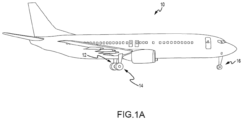
- the aircraft 10 includes landing gear, which may include a left main landing gear 12, a right main landing gear 14, and a nose landing gear 16.
- the landing gear support the aircraft 10 when it is not flying, allowing the aircraft 10 to taxi, take off, and land without damage. While the disclosure refers to the three landing gear configurations just described, the disclosure nevertheless contemplates any number of landing gear configurations.
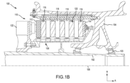
- a schematically depicted a brake mechanism 100 configured for use on a landing gear, such as, for example, each of the left main landing gear 12 and the right main landing gear 14 described above with reference to FIG. 1A .
- the brake mechanism 100 is mounted on an axle 102 for use with a wheel 104 disposed on and configured to rotate about the axle 102 via one or more bearing assemblies 103.
- a central axis 106 extends through the axle 102 and defines a center of rotation of the wheel 104.
- radial refers to directions perpendicular to a central axis 106 of fibrous preform
- axial refers to direction parallel to central axis 106
- circumferential reference to directions about central axis 106.
- a torque plate barrel 108 (sometimes referred to as a torque tube or a torque plate) is aligned concentrically with the central axis 106, and the wheel 104 is rotatable relative to the torque plate barrel 108.
- the brake mechanism 100 includes a piston assembly 110, a pressure plate 112 disposed adjacent the piston assembly 110, an end plate 114 positioned a distal location from the piston assembly 110, and a plurality of rotor disks 116 interleaved with a plurality of stator disks 118 positioned intermediate the pressure plate 112 and the end plate 114.
- the pressure plate 112, the plurality of rotor disks 116, the plurality of stator disks 118, and the end plate 114 together form a brake heat sink or brake stack 120.
- the pressure plate 112, the end plate 114, and the plurality of stator disks 118 are mounted to the torque plate barrel 108 and remain rotationally stationary relative to the axle 102.
- the plurality of rotor disks 116 is mounted to the wheel 104 and rotate with respect to each of the pressure plate 112, the end plate 114, and the plurality of stator disks 118.
- An actuating mechanism for the brake mechanism 100 includes a plurality of piston assemblies, including the piston assembly 110, circumferentially spaced around a piston housing 122 (only one piston assembly is illustrated in FIG. 1B ).
- the plurality of piston assemblies affects a braking action by urging the pressure plate 112 and the plurality of stator disks 118 into frictional engagement with the plurality of rotor disks 116 and against the end plate 114.
- the resulting frictional contact slows or stops or otherwise prevents rotation of the wheel 104.
- the brake disks of brake mechanism 100 are fabricated from various composite materials, such as, for example, carbon/carbon (C/C) composite or ceramic matrix composite (CMCs), that enable the brake disks to withstand and dissipate the heat generated during and following a braking action.
- C/C carbon/carbon
- CMCs ceramic matrix composite
- rotor disks 116 and/or stator disks 118 are each comprised of a carbon-carbon (C/C) material having a high specific heat particulate interspersed throughout the rotor disks 116 and/or stator disks 118, where high specific heat particulate includes any particulate or powder (typically ceramic) that raises the specific heat of the disk above that of C/C composite alone.
- the rotor disks 116 and/or stator disks 118 may comprise a C/C composite that includes a percentage of boron, a boron component, or other material having a high specific heat (i.e., a specific heat greater than the specific heat of the C/C composite alone).
- rotor disks 116 and/or stator disks 118 may comprise a C/C composite with a percentage of boron carbide (B 4 C) disposed substantially throughout the disk.
- the process of interspersing the boron carbide (or other high specific heat component) into the C/C composite is performed by a slurry infiltration process.
- the slurry may infiltrate a fiber preform employed to form the C/C composite in the radial, or in-plane, direction.
- the slurry may infiltrate via through thickness infiltration of the carbonize preforms.
- infiltrating in the radial, as opposed to the axial, direction may allow greater volumes and/or larger size particles to be infiltrated.
- Increasing the volume and/or size of the particles may facilitate the densification process by increasing the surface area available for the matrix material to bond to and by decreasing the open, or empty, volume within the preform.
- In-plane infiltration may also allow thicker fibrous preforms (e.g., fibrous preforms including a greater number of fiber layers) to be used in the manufacture rotor disks 116 and/or stator disks 118, as the compared to axial infiltration.
- Fibrous preform 130 may be employed to form a rotor disk 116 or a stator disk 118, as described above.
- Fibrous preform 130 may comprise a porous structure comprised of a plurality of stacked textile layers 132.
- Each textile layer 132 having a thickness in a first dimension (i.e., the Z-direction) that may be substantially less than a thickness of the layer 132 in the other two dimensions (i.e., the X-direction and the Y-direction).
- the "in-plane" direction refers to directions parallel to the thicker two dimensions (i.e., parallel to the X and Y directions and perpendicular to the Z-direction).
- a porous structure may comprise any structure derived from a fibrous material such as carbon fibers or the like.
- the carbon fibers may be derived from polyacrylonitrile (PAN), rayon (synthetic fiber derived from cellulose), oxidized polyacrylonitrile fiber (OPF), pitch, or the like.
- the starting fiber may be pre-oxidized PAN or fully carbonized commercial carbon fiber.
- Fibrous preform 130 may be prepared by needling the textile layers 132 of fibrous preform 130. Needling the textile layers 132 of fibrous preform 130 tends to push fibers from one layer 132 to the next layer 132, thereby forming z-fibers that extend axially across the layers 132.
- fibrous preform 130 may comprise fibers extending in three different directions: the radial direction, the circumferential direction, and the axial direction (or the X, Y, and Z directions).
- Fibrous preform 130 may be fabricated using a net shape preforming technology or may be cut from a needled board. Fibrous preform 130 may be a lay-up of woven, braided or knitted textile layers 132. The fibrous material may be in the form of chopped carbon fibers molded to form layers 132. Prior to the densification process, the fibrous material may be formed into a preform having any desired shape or form. For example, the fibrous preform may be in the form of a disk having any shape such as, for example, a polygon, a cylinder, a triangle, annular, square, rectangle, pentagon, hexagon, octagon, or the like. In various embodiments, layers 132 and fibrous preform 130 may have a generally annular shape.
- the outer circumferential (or outer perimeter) surfaces 134 of layers 132 may form an outer diameter (OD) 136 of fibrous preform 130, and the inner circumferential (or inner perimeter) surfaces 138 of layers 132 may form an inner diameter (ID) 140 of fibrous preform 130.
- Each layer 132 includes a first axial face 142 and a second axial face 144 opposite the first axial face 142.
- First and second axial faces 142, 144 extend from outer circumferential surface 134 to inner circumferential surface 138.
- Layers 132 are stacked such that the first axial face 142 of one layer 132 is oriented toward the second axial face 144 of the adjacent layer 132.
- First axial face 142 of the uppermost layer 132 forms the upper axial end 146 of fibrous preform 130 and the second axial face 144 of the bottommost layer 132 forms the lower axial end 147 of fibrous preform 130 (i.e., the two layers 132 that are farther apart from one another in the axial direction form the axial ends 146, 147 of the fibrous preform).
- fibrous preforms 130 being placed in a furnace 148 for carbonization is illustrated.
- the carbonization process may be employed to convert the fibers of the fibrous preforms 130 into pure carbon fibers, as used herein only "pure carbon fibers" means carbon fibers comprised of at least 99% carbon.
- the carbonization process is distinguished from the densification process described below in that the densification process involves infiltrating the pores of the fibrous preform 130 and depositing a matrix (e.g., carbon, phenolic resin, or any other desired matrix material) within and around the carbon fibers of the fibrous preform, and the carbonization process refers to the process of converting the fibers of the fibrous preform 130 into pure carbon fibers.
- a matrix e.g., carbon, phenolic resin, or any other desired matrix material
- a plurality of fibrous preforms 130 may be placed on top of one another with separator plates 150 and spacing stops 152 disposed between adjacent fibrous preforms 130.
- the bottommost fibrous preform 130 may be placed on a base plate 154 at the bottom of carbonization furnace 148.
- a separator plate 150 may be placed on top of the bottommost fibrous preform 130.
- Another fibrous preform 130 may then be placed on the separator plate 150, and another separator plate 150 may be placed on that fibrous preform 130.
- a stack of fibrous preforms 130 and separator plates 150 may be constructed in this manner, with each fibrous preform 130 being separated from superjacent and subjacent fibrous preforms 130 by separator plates 150.
- Stops 152 may be placed between each of the separator plates 150.
- the stops 152 may comprise a height that is less than the thickness of the fibrous preform 130 prior to carbonization. Stops 152 may define a target thickness of the fibrous preform 130 after carbonization. In that regard, after the stack of fibrous preforms 130 is constructed, and before the carbonization process has started, gaps may exist between the stops 152 and adjacent separator plates 150. During carbonization, a compressive load may be applied to the fibrous preforms 130, thereby compressing the fibrous preforms 130 until stops 152 contact adjacent separator plates 150.
- compressive pressure may be applied to fibrous preforms 130 during the carbonization.
- the compressive pressure may be applied by placing a weight 156 over fibrous preforms 130, or by applying a compressive load to the fibrous preforms 130 by other suitable means.
- the compressive pressure may be applied along the direction of the z-fibers. It will be appreciated by those skilled in the art that the mass of weight 156 and/or the compressive force generated by weight 156 may vary depending on the size of fibrous preforms 130, the pre-carbonization fiber volume of fibrous preforms 130, the desired post-carbonization fiber volume of fibrous preforms 130, and/or the number fibrous preforms 130 being compressed.
- fibrous preform 130 refers the percentage of the total volume of the fibrous preform that is formed by the fibers of the fibrous preform. For example, a fiber volume of 18% means the fibers of the fibrous preform form 18% of the total volume of fibrous preform.
- fibrous preform 130 after carbonization, fibrous preform 130 includes a fiber volume of between 10% and 50%. In various embodiments, after carbonization, fibrous preform 130 includes a fiber volume of between 15% and 25%. In various embodiments, fibrous preforms 130 having a low fiber volume may be desirable for the infiltration methods disclosed herein. In various embodiments, after carbonization, fibrous preform 130 may comprise a fiber volume of less than 25%. For example, in various embodiments, after carbonization, fibrous preform 130 may comprise a fiber volume of 21% or, in various embodiments, fibrous preform 130 may comprise a fiber volume of 18%.
- fibrous preform 130 may be densified using, for example, CVI.
- fibrous preform 130 prior to densification, fibrous preform 130 is infiltrated with a slurry including a high specific heat particulate.
- fibrous preform 130 is infiltrated with a ceramic slurry (i.e., a slurry comprised of a liquid carrier and ceramic particulates).
- the slurry infiltration process includes preparation of a slurry including a ceramic particulate (e.g., an aqueous B 4 C-based slurry) and immersing the carbonized fibrous preform 130 into the slurry for a period of time sufficient for the particulate (e.g., the B 4 C) to infiltrate the fibrous preform 130.
- a ceramic particulate e.g., an aqueous B 4 C-based slurry
- immersing the carbonized fibrous preform 130 into the slurry for a period of time sufficient for the particulate (e.g., the B 4 C) to infiltrate the fibrous preform 130.
- the slurry includes sacrificial fibers.
- the sacrificial fibers / particulates are mixed into the slurry.
- the sacrificial fibers may be a polyethylene or polyester fiber such that, in response to heating to carbon CVI temperatures (e.g., 100°F and 205°F (38°C and 96°C)) will burn.
- the preform is heated up to 1000°C in order to cause the sacrificial fibers for burn away, or decompose.
- channels are formed, thus improving carbon CVI infiltration. For instance, the channels provide a pathway for the CVI to get to in.
- polyester or polyethylene fibers may be too large to incorporate directly into the B 4 C slurry.
- the sacrificial fibers may be injected into the fibrous preform 130.
- the sacrificial fibers may be injected using a syringe or other means, prior to completing B 4 C slurry infiltration.
- the sacrificial fibers may be distributed in the matrix of the boron carbide.
- Slurry may include high specific heat particulate and a liquid carrier (such as, for example, water and/or alcohol).
- slurry may further include a high specific heat particulate, a binder (e.g., a polymeric adhesive or polyvinyl acetate), and a liquid carrier (e.g., water).
- a binder e.g., a polymeric adhesive or polyvinyl acetate
- a liquid carrier e.g., water
- slurry may be a B 4 C-based slurry and may be prepared by mixing B 4 C powder in water with appropriate additives, such as wetting agents and dispersants.
- the B 4 C powder may comprise particulates having an average particle sizes from sub-micron up to about 30 microns. As used in the previous context only, "about" means ⁇ 5 microns.
- the slurry further includes the sacrificial fibers.
- the sacrificial fibers are added to the solution of the slurry.
- the sacrificial fibers make up 5% of the slurry solution.
- the sacrificial fibers make up 10 % of the slurry solution.
- the sacrificial fibers make up .5% - 10% of the slurry.
- the sacrificial fibers may be a micro polyester particle.
- the slurry solution may be loaded into the syringe. A user may then use the syringe to inject the slurry, including the sacrificial fibers, into the fibrous preform 130.
- the user may inject the fibrous preform 130 in a plurality of locations. For instance, the user may inject/poke the fibrous preform 130 at ten locations.
- a bank of syringes may be provided to operate as an assembly-line system to prepare multiple fibrous preforms may be injected simultaneously with the sacrificial fibers.
- Infiltration using a syringe facilitates achieving a uniform distribution of the sacrificial fibers, which in turn improves carbon CVI infiltration once the fibers are burned around during the heat-up to carbon CVI process temperature.
- the brakes may be manufactured smaller, for instance. Further, the friction and wear characteristics may be improved.
- the process illustrated and described with respect to FIG. 3 is the emission of off gases that include but are not limited to hydrogen (H 2 ) and carbon dioxide (CO 2 ).
- off gases include but are not limited to hydrogen (H 2 ) and carbon dioxide (CO 2 ).
- FIG. 4 in accordance with various embodiments, a system 400 for energy recovery of converting recovered CO 2 into other products is illustrated.
- the C/C preform production process 402 utilizes natural gas such as methane (CH 4 ) 403 to perform various operations in the production of the aircraft brakes.
- CH 4 methane
- various off gases 404 i.e. hydrocarbons
- the C/C preform production process 402 feeds the various off gases 404, i.e., hydrocarbons, CO 2 , H 2 , and nitrogen (N 2 ), among others, into H 2 separator 406.
- H 2 separator 406 separates H 2 408 from the various off gases 404 using one or more of membrane separation, pressure swing absorption (PSA), captured by solid sorbents, or cryogenic distillation, among others.
- PSA pressure swing absorption
- the H 2 separator 406 feeds the H 2 408 into methanization reactor 410 and feeds the remaining off gases 412, i.e. heavier hydrocarbons, as well as CO 2 and N 2 , among others, into burner/steam generator 414.
- the burner/steam generator 414 burns the remaining off gases 412 utilizing air 416 to generate steam 418 from incoming water (H 2 O) 420.
- the steam 418 may be utilized to operate other components of the C/C preform production process 402.
- the burner/steam generator 414 in addition to generating the steam 418, the burner/steam generator 414 generates byproducts 422, such as such as CO 2 , H 2 O, and N 2 , among others, which the burner/steam generator 414 feeds into separator 424.
- Separator 424 may operate to separate the CO 2 426 from the byproducts 422, which is fed into methanization reactor 410, to separate the N 2 428 from the byproducts 422, which may be released into the atmosphere, and to separate the H 2 O 430 from the byproducts 422, which may be fed into the burner/steam generator 414 along with H 2 O 420.
- the separator 424 may one or more of absorption, adsorption, cryogenic distillation, captured by solid sorbents or solvents such as mono-ethanol amine (MEA), or membrane separation, among others for the separation process.
- the methanization reactor 410 utilizes the incoming H 2 408 and CO 2 426 to perform a methanization process in order to produce methane (CH 4 ) 432, which is fed into the C/C preform production process 402 or another system to perform various operations in the production the aircraft brakes, such as heat generation.
- the methanization reactor 410 in the production of CH 4 432, also produces heat and/or steam 434 in the form of a gas exhaust and/or steam exhaust, which is fed into heat recovery unit 440.
- the heat recovery unit 440 may operate to utilize the heat and/or steam 434 to generate energy 442, i.e.
- the heat recovery unit 440 may feed the energy 442, i.e. the heat transfer fluid, via a closed loop process, to separator 424 in order for separator 424 to utilize the provided heat to separate the CO 2 426 from the byproducts 422, which is fed into methanization reactor 410, to separate the N 2 428 from the byproducts 422, which may be released into the atmosphere, and to separate the H 2 O 430 from the byproducts 422, which may be fed into the burner/steam generator 414 along with H 2 O 420.
- the heat recovery unit 440 may operate to utilize the heat and/or steam 434 to generate energy 444, i.e.
- the heat recovery unit 440 may feed the energy 444, i.e. the heat transfer fluid, via a closed loop process, to the C/C preform production process 402 in order that the C/C preform production process 402 uses the heat for performing various operations in the production of the aircraft brakes.
- the heat recovery unit 440 may feed the heat and/or steam 434 as energy 442, via a closed loop process, to separator 424 in order for separator 424 to separate the CO 2 426 from the byproducts 422, which is fed into methanization reactor 410, to separate the N 2 428 from the byproducts 422, which may be released into the atmosphere, and to separate the H 2 O 430 from the byproducts 422, which may be fed into the burner/steam generator 414 along with H 2 O 420.
- the heat recovery unit 440 may feed the heat and/or steam 434 as energy 444, via a closed loop process, to the C/C preform production process 402 for use in performing various operations in the production of the aircraft brakes.
- the heat recovery unit 440 may operate to utilize the heat and/or steam 434 to operate a turbine of an electric generator, thereby producing energy 442, i.e. electricity.
- the heat recovery unit 440 may feed the energy 442, i.e. the electricity, to separator 424 in order for separator 424 to utilize the energy 442 to produce electric heat to separate the CO 2 426 from the byproducts 422, which is fed into methanization reactor 410, to separate the N 2 428 from the byproducts 422, which may be released into the atmosphere, and to separate the H 2 O 430 from the byproducts 422, which may be fed into the burner/steam generator 414 along with H 2 O 420.
- the heat recovery unit 440 may operate to utilize the heat and/or steam 434 to operate a turbine of an electric generator, thereby producing energy 444, i.e. electricity.
- the heat recovery unit 440 may feed the energy 444, i.e. the electricity, to the C/C preform production process 402 to utilize the energy 442 to produce electric heat in order that the C/C preform production process 402 uses the heat for performing various operations in the production of the aircraft brakes.
- the heat recovery unit 440 using the heat and/or steam 434 to operate a turbine of an electric generator, thereby producing energy 442, 444, i.e. electricity, any excess energy, 446, i.e. electricity, may be fed into other processes within a plant where the C/C preform production process 402 operates or sold as excess energy to an electric provider via an electric grid.
- excess steam 448 of the heat and/or steam 434 may then be condensed to generate H 2 O 438, which may be fed into the burner/steam generator 414 along with H 2 O 420 and H 2 O 430.
- the condensing may be performed by the heat recovery unit 440 in response the heat recovery unit 440 is able to remove enough heat from the heat and/or steam 434.
- the excess steam 448 may be fed to condenser 436.
- the condenser 436 condenses the excess steam 448. Accordingly, system 400 provides for CO 2 emission recovery by converting the recovered CO 2 into other products that may be utilized by the C/C preform production process 402.
- the C/C preform production process 502 utilizes natural gases such as methane (CH 4 ) 503 to perform various operation in the production the aircraft brakes.
- various off gases 504 i.e. hydrocarbons
- the C/C preform production process 502 feeds the various off gases 504, i.e., hydrocarbons, CO 2 , H 2 , and nitrogen (N 2 ), among others, into burner/steam generator 514.
- the burner/steam generator 514 burns the various off gases 504 utilizing air 516 to generate steam 518 from incoming water (H 2 O) 520.
- the steam 518 may be utilized to operate other components of the C/C preform production process 502.
- the burner/steam generator 514 in addition to generating the steam 518, the burner/steam generator 514 generates byproducts 522, such as CO 2 , H 2 O, and N 2 , among others, which the burner/steam generator 514 feeds into separator 524.
- Separator 524 may operate to separate the CO 2 526 from the byproducts 522, which is fed into methanization reactor 510, to separate the N 2 528 from the byproducts 522, which may be released into the atmosphere, and to separate the H 2 O 530 from the byproducts 522, which may be fed into the burner/steam generator 514 along with H 2 O 420.
- the separator 524 may be one or more of absorption, adsorption, cryogenic distillation, captured by solid sorbents or solvents such as mono-ethanol amine (MEA), or membrane separation, among others for the separation process.
- MEA mono-ethanol amine
- the methanization reactor 510 utilizes the incoming H 2 508 provided via green H 2 supply 540 and CO 2 526 to perform a methanization process in order to produce methane (CH 4 ) 532, which is fed into the C/C preform production process 502 or another system to perform various operations in the production the aircraft brakes, such as heat generation.
- green H 2 supply 540 may be H 2 generated sustainably via electrolysis from a green H 2 supply device, such as a solar generator or wind generator.
- the methanization reactor 510 in the production of CH 4 532, the methanization reactor 510 also produces heat and/or steam 534 in the form of a gas exhaust and/or steam exhaust, which is fed into heat recovery unit 540.
- the heat recovery unit 540 may operate to utilize the heat and/or steam 534 to generate energy 542, i.e. heat, via thermal transfer, another fluid that, once heated, may be utilized as a heat transfer fluid. In various embodiments, the heat recovery unit 540 may feed the energy 542, i.e.
- the heat transfer fluid via a closed loop process, to separator 524 in order for separator 524 to utilize the provided heat to separate the CO 2 526 from the byproducts 522, which is fed into methanization reactor 510, to separate the N 2 528 from the byproducts 522, which may be released into the atmosphere, and to separate the H 2 O 530 from the byproducts 522, which may be fed into the burner/steam generator 514 along with H 2 O 520.
- the heat recovery unit 540 may operate to utilize the heat and/or steam 534 to generate energy 544, i.e. heat, via thermal transfer, another fluid that, once heated, may be utilized as a heat transfer fluid.
- the heat recovery unit 540 may feed the energy 544, i.e. the heat transfer fluid, via a closed loop process, to the C/C preform production process 502 in order that the C/C preform production process 502 uses the heat for performing various operations in the production of the aircraft brakes.
- the heat recovery unit 540 may feed the heat and/or steam 534 as energy 542, via a closed loop process, to separator 524 in order for separator 524 to separate the CO 2 526 from the byproducts 522, which is fed into methanization reactor 510, to separate the N 2 528 from the byproducts 522, which may be released into the atmosphere, and to separate the H 2 O 530 from the byproducts 522, which may be fed into the burner/steam generator 514 along with H 2 O 520.
- the heat recovery unit 540 may feed the heat and/or steam 534 as energy 544, via a closed loop process, to the C/C preform production process 502 for use in performing various operations in the production of the aircraft brakes.
- the heat recovery unit 540 may operate to utilize the heat and/or steam 534 to operate a turbine of an electric generator, thereby producing energy 542, i.e. electricity.
- the heat recovery unit 540 may feed the energy 542, i.e. the electricity, to separator 524 in order for separator 524 to utilize the energy 542 to produce electric heat to separate the CO 2 526 from the byproducts 522, which is fed into methanization reactor 510, to separate the N 2 528 from the byproducts 522, which may be released into the atmosphere, and to separate the H 2 O 530 from the byproducts 522, which may be fed into the burner/steam generator 514 along with H 2 O 520.
- the heat recovery unit 540 may operate to utilize the heat and/or steam 534 to operate a turbine of an electric generator, thereby producing energy 544, i.e. electricity.
- the heat recovery unit 540 may feed the energy 544, i.e. the electricity, to the C/C preform production process 502 to utilize the energy 542 to produce electric heat in order that the C/C preform production process 502 uses the heat for performing various operations in the production of the aircraft brakes.
- the heat recovery unit 540 using the heat and/or steam 534 to operate a turbine of an electric generator, thereby producing energy 542, 544, i.e. electricity, any excess energy, 546, i.e. electricity, may be fed into other processes within a plant where the C/C preform production process 502 operates or sold as excess energy to an electric provider via an electric grid.
- excess steam 548 of the heat and/or steam 534 may then be condensed to generate H 2 O 538, which may be fed into the burner/steam generator 514 along with H 2 O 520 and H 2 O 530.
- the condensing may be performed by the heat recovery unit 540 in response the heat recovery unit 540 is able to remove enough heat from the heat and/or steam 534.
- the excess steam 548 may be fed to condenser 536.
- the condenser 536 condenses the excess steam 548. Accordingly, system 500 provides for CO 2 emission recovery by converting the recovered CO 2 into other products that may be utilized by the C/C preform production process 502.
- the C/C preform production process 602 utilizes natural gases such as methane (CH 4 ) 603 to perform various operations in the production of aircraft brakes.
- various off gases 604 i.e. hydrocarbons
- the C/C preform production process 602 feeds the various off gases 604, i.e., hydrocarbons, CO 2 , H 2 , and nitrogen (N 2 ), among others, into H 2 separator 606.
- H 2 separator 606 separates H 2 608 from the various off gases 604 using one or more of membrane separation, pressure swing absorption (PSA), captured by solid sorbents, or cryogenic distillation, among others.
- PSA pressure swing absorption
- the H 2 separator 606 feeds the H 2 608 into methanization reactor 610 and feeds the remaining off gases 612, i.e. heavier hydrocarbons, as well as CO 2 and N 2 , among others, into burner/steam generator 614.
- the burner/steam generator 614 burns the remaining off gases 612 utilizing air 616 to generate steam 618 from incoming water (H 2 O) 620.
- the steam 618 may be utilized to operate other components of the C/C preform production process 602.
- the burner/steam generator 614 in addition to generating the steam 618, the burner/steam generator 614 generates byproducts 622, such as such as CO 2 , H 2 O, and N 2 , among others, which the burner/steam generator 614 feeds into separator 624.
- Separator 624 may operate to separate the CO 2 626 from the byproducts 622, which is fed into methanization reactor 610, to separate the N 2 628 from the byproducts 622, which may be released into the atmosphere, and to separate the H 2 O 630 from the byproducts 622, which may be fed into the burner/steam generator 614 along with H 2 O 620.
- the separator 624 may one or more of absorption, adsorption, cryogenic distillation, captured by solid sorbents or solvents such as mono-ethanol amine (MEA), or membrane separation, among others for the separation process.
- the methanization reactor 610 utilizes the incoming H 2 608, which may be supplemented by green H 2 supply 640, and CO 2 626 to perform a methanization process in order to produce methane (CH 4 ) 632, which is fed into the C/C preform production process 602 or another system to perform various operation in the production the aircraft brakes, such as heat generation.
- green H 2 supply 640 may be H 2 generated sustainably via electrolysis from a green H 2 supply device, such as a solar generator or wind generator.
- the methanization reactor 610 in the production of CH 4 632, the methanization reactor 610 also produces heat and/or steam 634 in the form of a gas exhaust and/or steam exhaust, which is fed into heat recovery unit 640.
- the heat recovery unit 640 may operate to utilize the heat and/or steam 634 to generate energy 642, i.e. heat, via thermal transfer, another fluid that, once heated, may be utilized as a heat transfer fluid. In various embodiments, the heat recovery unit 640 may feed the energy 642, i.e.
- the heat transfer fluid via a closed loop process, to separator 624 in order for separator 624 to utilize the provided heat to separate the CO 2 626 from the byproducts 622, which is fed into methanization reactor 610, to separate the N 2 628 from the byproducts 622, which may be released into the atmosphere, and to separate the H 2 O 630 from the byproducts 622, which may be fed into the burner/steam generator 614 along with H 2 O 620.
- the heat recovery unit 640 may operate to utilize the heat and/or steam 634 to generate energy 644, i.e. heat, via thermal transfer, another fluid that, once heated, may be utilized as a heat transfer fluid.
- the heat recovery unit 640 may feed the energy 644, i.e. the heat transfer fluid, via a closed loop process, to the C/C preform production process 602 in order that the C/C preform production process 602 uses the heat for performing various operations in the production of the aircraft brakes.
- the heat recovery unit 640 may feed the heat and/or steam 634 as energy 642, via a closed loop process, to separator 624 in order for separator 624 to separate the CO 2 626 from the byproducts 622, which is fed into methanization reactor 610, to separate the N 2 628 from the byproducts 622, which may be released into the atmosphere, and to separate the H 2 O 630 from the byproducts 622, which may be fed into the burner/steam generator 614 along with H 2 O 620.
- the heat recovery unit 640 may feed the heat and/or steam 634 as energy 644, via a closed loop process, to the C/C preform production process 602 for use in performing various operations in the production of the aircraft brakes.
- the heat recovery unit 640 may operate to utilize the heat and/or steam 634 to operate a turbine of an electric generator, thereby producing energy 642, i.e. electricity.
- the heat recovery unit 640 may feed the energy 642, i.e. the electricity, to separator 624 in order for separator 624 to utilize the energy 642 to produce electric heat to separate the CO 2 626 from the byproducts 622, which is fed into methanization reactor 610, to separate the N 2 628 from the byproducts 622, which may be released into the atmosphere, and to separate the H 2 O 630 from the byproducts 622, which may be fed into the burner/steam generator 614 along with H 2 O 620.
- the heat recovery unit 640 may operate to utilize the heat and/or steam 634 to operate a turbine of an electric generator, thereby producing energy 644, i.e. electricity.
- the heat recovery unit 640 may feed the energy 644, i.e. the electricity, to the C/C preform production process 602 to utilize the energy 642 to produce electric heat in order that the C/C preform production process 602 uses the heat for performing various operations in the production of the aircraft brakes.
- the heat recovery unit 640 using the heat and/or steam 634 to operate a turbine of an electric generator, thereby producing energy 642, 644, i.e. electricity, any excess energy, 646, i.e. electricity, may be fed into other processes within a plant where the C/C preform production process 602 operates or sold as excess energy to an electric provider via an electric grid.
- excess steam 648 of the heat and/or steam 634 may then be condensed to generate H 2 O 638, which may be fed into the burner/steam generator 614 along with H 2 O 620 and H 2 O 630.
- the condensing may be performed by the heat recovery unit 640 in response the heat recovery unit 640 is able to remove enough heat from the heat and/or steam 634.
- the excess steam 648 may be fed to condenser 636.
- the condenser 636 condenses the excess steam 648. Accordingly, system 600 provides for CO 2 emission recovery by converting the recovered CO 2 into other products that may be utilized by the C/C preform production process 602.
- a heat recovery unit receives at least one of heat or steam from a methanization reactor operating to convert carbon dioxide (CO 2 ) and supplied hydrogen (H 2 ) via methanization to produce methane (CH 4 ).
- the heat recovery unit generates energy using at least one of the heat or the steam from the methanization reactor.
- the heat recovery unit supplies the generated energy to at least one of a carbon/carbon (C/C) preform production process, a separator, or another system.
- C/C carbon/carbon
- references to "one embodiment,” “an embodiment,” “various embodiments,” etc. indicate that the embodiment described may include a particular feature, structure, or characteristic, but every embodiment may not necessarily include the particular feature, structure, or characteristic. Moreover, such phrases are not necessarily referring to the same embodiment. Further, when a particular feature, structure, or characteristic is described in connection with an embodiment, it is submitted that it is within the knowledge of one skilled in the art to affect such feature, structure, or characteristic in connection with other embodiments whether or not explicitly described. After reading the description, it will be apparent to one skilled in the relevant art(s) how to implement the disclosure in alternative embodiments.
- Numbers, percentages, or other values stated herein are intended to include that value, and also other values that are about or approximately equal to the stated value, as would be appreciated by one of ordinary skill in the art encompassed by various embodiments of the present disclosure.
- a stated value should therefore be interpreted broadly enough to encompass values that are at least close enough to the stated value to perform a desired function or achieve a desired result.
- the stated values include at least the variation to be expected in a suitable industrial process, and may include values that are within 10%, within 6%, within 1%, within 0.1%, or within 0.01% of a stated value.
- the terms “substantially,” “about,” or “approximately” as used herein represent an amount close to the stated amount that still performs a desired function or achieves a desired result.
- the term “substantially,” “about,” or “approximately” may refer to an amount that is within 10% of, within 6% of, within 1% of, within 0.1 % of, and within 0.01% of a stated amount
Landscapes
- Chemical & Material Sciences (AREA)
- Engineering & Computer Science (AREA)
- Chemical Kinetics & Catalysis (AREA)
- Organic Chemistry (AREA)
- Oil, Petroleum & Natural Gas (AREA)
- General Chemical & Material Sciences (AREA)
- Ceramic Engineering (AREA)
- Environmental & Geological Engineering (AREA)
- Manufacturing & Machinery (AREA)
- Analytical Chemistry (AREA)
- Health & Medical Sciences (AREA)
- Biomedical Technology (AREA)
- Structural Engineering (AREA)
- Materials Engineering (AREA)
- Mechanical Engineering (AREA)
- Aviation & Aerospace Engineering (AREA)
- Dispersion Chemistry (AREA)
- Combustion & Propulsion (AREA)
- Inorganic Chemistry (AREA)
- Thermal Sciences (AREA)
- Physics & Mathematics (AREA)
- Composite Materials (AREA)
- Braking Arrangements (AREA)
Abstract
Description
- The present disclosure relates generally to carbon dioxide (CO2) emission recovery, and more particularly, energy recovery in a preform production process.
- Composite bodies are utilized in various industries, including the aerospace industry. The composite bodies start with a preform that is formed using layers of textile material. Aircraft C/C brake manufacturing is one point source of carbon dioxide (CO2) emissions. Other point sources of CO2 emissions may include thermal protections systems and shaped composite bodies, among others. In such manufacturing, sustainability goals may be to decarbonize operations by a predetermined percentage by a future date. However, capturing CO2 emissions is not only expensive but also problematic to store. This is especially true for CO2 emission sources that do not generate enough CO2 emissions to justify use of a pipeline for underground sequestration.
- According to one aspect of the present invention, a system for energy recovery is provided. The system includes a heat recovery unit. The heat recovery unit is configured to receive at least one of heat or steam from a methanization reactor operating to convert carbon dioxide (CO2) and supplied hydrogen (H2) via methanization to produce methane (CH4), generate energy using at least one of the heat or the steam from the methanization reactor, and supply the energy to at least one of a carbon/carbon (C/C) preform production process, a separator, or another system.
- In various embodiments, the system further includes a heat transfer fluid. In various embodiments, the heat recovery unit uses at least one of the heat or the steam to heat the heat transfer fluid. In various embodiments, the heat transfer fluid transfers heat to at least one of the C/C preform production process or the separator. In various embodiments, the system further includes the C/C preform production process. In various embodiments, the C/C preform production process is configured to utilize the heat to produce an aircraft brake and, in the process, generate various off gases from which the supplied H2 is separated. In various embodiments, the system further includes the separator. In various embodiments, the separator is configured to utilize the heat to separate the CO2 from byproducts received from a burner/steam generator and provide the CO2 to the methanization reactor. In various embodiments, the separator is further configured to separate nitrogen (N2) from the byproducts and release the N2 into an atmosphere. In various embodiments, the separator is further configured to separate water (H2O) from the byproducts and feeds the H2O into the burner/steam generator.
- In various embodiments, the heat recovery unit uses the steam to transfer heat to at least one of the C/C preform production process or the separator. In various embodiments, the system further includes a turbine. In various embodiments, the heat recovery unit uses the at least one of the heat or the steam to operate the turbine to produce electricity. In various embodiments, the electricity is either utilized to generate heat in at least one of the C/C preform production process, the separator, or the other system or utilized as direct power for operations to power equipment or processes.
- In various embodiments, the system further includes a burner/steam generator. In various embodiments, in generating the energy using the steam from the methanization reactor, the heat recovery unit is configured to condense excess steam to water (H2O) which is supplied to the burner/steam generator. In various embodiments, the system further includes a burner/steam generator and a condenser. In various embodiments, in generating the energy using the steam from the methanization reactor, the heat recovery unit provides excess steam to the condenser. In various embodiments, the condenser is configured to condense the steam to water (H2O) which is supplied to the burner/steam generator.
- Also disclosed herein is a method for energy recovery. The method includes receiving, by a heat recovery unit, at least one of heat or steam from a methanization reactor operating to convert carbon dioxide (CO2) and supplied hydrogen (H2) via methanization to produce methane (CH4), generating, by the heat recovery unit, energy using at least one of the heat or the steam from the methanization reactor, and supplying, by the heat recovery unit, the energy to at least one of a carbon/carbon (C/C) preform production process, a separator, or another system.
- In various embodiments, the heat recovery unit uses at least one of the heat or the steam to heat a heat transfer fluid. In various embodiments, the heat transfer fluid transfers heat to at least one of the C/C preform production process or the separator. In various embodiments, the C/C preform production process is configured to utilize the heat to produce an aircraft brake and, in the process, generate various off gases from which the supplied H2 is separated. In various embodiments, the separator is configured to utilize the heat to separate the CO2 from byproducts received from a burner/steam generator and provide the CO2 to the methanization reactor. In various embodiments, the separator is further configured to separate nitrogen (N2) from the byproducts and release the N2 into an atmosphere. In various embodiments, the separator is further configured to separate water (H2O) from the byproducts and feeds the H2O into the burner/steam generator.
- In various embodiments, the heat recovery unit uses the steam to transfer heat to at least one of the C/C preform production process or the separator. In various embodiments, the heat recovery unit uses the at least one of the heat or the steam to operate a turbine to produce electricity. In various embodiments, the electricity is either utilized to generate heat in at least one of the C/C preform production process, the separator, or the other system or utilized as direct power for operations to power equipment or processes. In various embodiments, in generating the energy using the steam from the methanization reactor, the heat recovery unit is configured to condense excess steam to water (H2O) which is supplied to a burner/steam generator. In various embodiments, in generating the energy using the steam from the methanization reactor, the heat recovery unit provides excess steam to a condenser. In various embodiments, the condenser is configured to condense the steam to water (H2O) which is supplied to a burner/steam generator.
- The forgoing features and elements may be combined in various combinations without exclusivity, unless expressly indicated herein otherwise. These features and elements as well as the operation of the disclosed embodiments will become more apparent in light of the following description and accompanying drawings.
-
-
FIG. 1A illustrates an exemplary aircraft having a brake system, in accordance with various embodiments. -
FIG. 1B illustrates a cross-sectional view of a brake assembly, in accordance with various embodiments. -
FIG. 2 illustrates a fibrous preform, in accordance with various embodiments. -
FIG. 3 illustrates a fibrous preform in a carbonization furnace, in accordance with various embodiments. -
FIG. 4 illustrates a system for energy recovery of converting recovered CO2 into other products, in accordance with various embodiments. -
FIG. 5 illustrates a system for energy recovery of converting recovered CO2 into other products, in accordance with various embodiments. -
FIG. 6 illustrates a system for energy recovery of converting recovered CO2 into other products, in accordance with various embodiments. -
FIG. 7 illustrates a method for energy recovery of converting recovered CO2 into other products, in accordance with various embodiments. - The following detailed description of various embodiments herein makes reference to the accompanying drawings, which show various embodiments by way of illustration. While these various embodiments are described in sufficient detail to enable those skilled in the art to practice the disclosure, it should be understood that other embodiments may be realized and that changes may be made without departing from the scope of the invention as defined by the claims. Thus, the detailed description herein is presented for purposes of illustration only and not of limitation. Furthermore, any reference to singular includes plural embodiments, and any reference to more than one component or step may include a singular embodiment or step. Also, any reference to attached, fixed, connected, or the like may include permanent, removable, temporary, partial, full or any other possible attachment option. Additionally, any reference to without contact (or similar phrases) may also include reduced contact or minimal contact. It should also be understood that unless specifically stated otherwise, references to "a," "an," or "the" may include one or more than one and that reference to an item in the singular may also include the item in the plural. Further, all ranges may include upper and lower values and all ranges and ratio limits disclosed herein may be combined.
- In some typical carbon/carbon (C/C) preform production process, such as aircraft C/C brake manufacturing, thermal protections systems, and shaped composite bodies, among others, carbon dioxide (CO2) emissions account for a substantial percentage of a total CO2 emissions for some corporations. In such corporations, sustainability goals may be to decarbonize operations by a predetermined percentage by a future date. While technology for capturing CO2 emissions may be well-established and already in practice for applications ranging from enhanced oil recovery to carbonation of soft drinks, one of the costs associated with capturing CO2 emissions is the logistics and additional energy input associated with CO2 emission sequestration, which, for large point sources such as power plants, involves pressurization and transfer via pipeline to underground storage locations. Such CO2 emission recovery is unlikely to become a viable solution for relatively small CO2 emission point sources.
- Disclosed herein are systems and methods for energy recovery of converting recovered CO2 into other products. Accordingly, in various embodiments, in manufacturing processes where other gases such as hydrogen (H2) are also generated as a byproduct, the H2 may react catalytically with the recovered CO2 to form methane (CH4) via a methanization reaction, i.e., the main species in natural gas:
CO2 + 4H2 → CH4 + 2H2O
This methanization reaction may also be referred to as a Sabatier reaction. In manufacturing processes, such as preform forming manufacturing, the methanization reaction offers the most straightforward path for management of CO2 emissions, given that the preform forming manufacturing process already typically utilizes methane (natural gas) for operation and given that the C/C brake manufacturing process generates excess H2. While the excess H2 generated by the C/C brake manufacturing process may not be enough to account for the entire CO2 emissions, the H2 may be supplemented with additional "green hydrogen" (i.e., produced sustainably), which is projected to become widely available. Additionally, in various embodiments, heat generated during the methanization reaction as well as any steam (H2O) produced from the methanization reactor may also be utilized on a bottoming cycle, where waste heat and steam generated during the CO2 capture process is used for indirect heat and/or electric heat, which may be utilized in the manufacturing processes. That is, in various embodiments, enthalpy of the reaction from the methanization reactor is approximately -165.4 kilojoules per mole (kJ/mol), i.e. a loss of energy due to an exothermic reaction, which provides a significant energy stream for thermal recovery. - Referring now to
FIG. 1A , in accordance with various embodiments, anaircraft 10 is illustrated. Theaircraft 10 includes landing gear, which may include a leftmain landing gear 12, a rightmain landing gear 14, and anose landing gear 16. The landing gear support theaircraft 10 when it is not flying, allowing theaircraft 10 to taxi, take off, and land without damage. While the disclosure refers to the three landing gear configurations just described, the disclosure nevertheless contemplates any number of landing gear configurations. - Referring now to
FIG. 1B , in accordance with various embodiments, a schematically depicted abrake mechanism 100 is illustrated configured for use on a landing gear, such as, for example, each of the leftmain landing gear 12 and the rightmain landing gear 14 described above with reference toFIG. 1A . In various embodiments, thebrake mechanism 100 is mounted on anaxle 102 for use with awheel 104 disposed on and configured to rotate about theaxle 102 via one ormore bearing assemblies 103. Acentral axis 106 extends through theaxle 102 and defines a center of rotation of thewheel 104. As used herein, the term "radial" refers to directions perpendicular to acentral axis 106 of fibrous preform, the term "axial" refers to direction parallel tocentral axis 106, and the term "circumferential" reference to directions aboutcentral axis 106. A torque plate barrel 108 (sometimes referred to as a torque tube or a torque plate) is aligned concentrically with thecentral axis 106, and thewheel 104 is rotatable relative to thetorque plate barrel 108. - The
brake mechanism 100 includes apiston assembly 110, apressure plate 112 disposed adjacent thepiston assembly 110, anend plate 114 positioned a distal location from thepiston assembly 110, and a plurality ofrotor disks 116 interleaved with a plurality ofstator disks 118 positioned intermediate thepressure plate 112 and theend plate 114. Thepressure plate 112, the plurality ofrotor disks 116, the plurality ofstator disks 118, and theend plate 114 together form a brake heat sink orbrake stack 120. Thepressure plate 112, theend plate 114, and the plurality ofstator disks 118 are mounted to thetorque plate barrel 108 and remain rotationally stationary relative to theaxle 102. The plurality ofrotor disks 116 is mounted to thewheel 104 and rotate with respect to each of thepressure plate 112, theend plate 114, and the plurality ofstator disks 118. - An actuating mechanism for the
brake mechanism 100 includes a plurality of piston assemblies, including thepiston assembly 110, circumferentially spaced around a piston housing 122 (only one piston assembly is illustrated inFIG. 1B ). Upon actuation, the plurality of piston assemblies affects a braking action by urging thepressure plate 112 and the plurality ofstator disks 118 into frictional engagement with the plurality ofrotor disks 116 and against theend plate 114. Through compression of the plurality ofrotor disks 116 and the plurality ofstator disks 118 between thepressure plate 112 and theend plate 114, the resulting frictional contact slows or stops or otherwise prevents rotation of thewheel 104. In various embodiments, the brake disks of brake mechanism 100 (e.g.,rotor disks 116 and the stator disks 118) are fabricated from various composite materials, such as, for example, carbon/carbon (C/C) composite or ceramic matrix composite (CMCs), that enable the brake disks to withstand and dissipate the heat generated during and following a braking action. - In accordance with various embodiments,
rotor disks 116 and/orstator disks 118 are each comprised of a carbon-carbon (C/C) material having a high specific heat particulate interspersed throughout therotor disks 116 and/orstator disks 118, where high specific heat particulate includes any particulate or powder (typically ceramic) that raises the specific heat of the disk above that of C/C composite alone. For example, in various embodiments, therotor disks 116 and/orstator disks 118 may comprise a C/C composite that includes a percentage of boron, a boron component, or other material having a high specific heat (i.e., a specific heat greater than the specific heat of the C/C composite alone). In various embodiments,rotor disks 116 and/orstator disks 118 may comprise a C/C composite with a percentage of boron carbide (B4C) disposed substantially throughout the disk. - In various embodiments, the process of interspersing the boron carbide (or other high specific heat component) into the C/C composite is performed by a slurry infiltration process. As described in further detail below, the slurry may infiltrate a fiber preform employed to form the C/C composite in the radial, or in-plane, direction. The slurry may infiltrate via through thickness infiltration of the carbonize preforms. In various embodiments infiltrating in the radial, as opposed to the axial, direction may allow greater volumes and/or larger size particles to be infiltrated. Increasing the volume and/or size of the particles may facilitate the densification process by increasing the surface area available for the matrix material to bond to and by decreasing the open, or empty, volume within the preform. In-plane infiltration may also allow thicker fibrous preforms (e.g., fibrous preforms including a greater number of fiber layers) to be used in the
manufacture rotor disks 116 and/orstator disks 118, as the compared to axial infiltration. - Referring now to
FIG. 2 , in accordance with various embodiments, afibrous preform 130 is illustrated.Fibrous preform 130 may be employed to form arotor disk 116 or astator disk 118, as described above.Fibrous preform 130 may comprise a porous structure comprised of a plurality of stacked textile layers 132. Eachtextile layer 132 having a thickness in a first dimension (i.e., the Z-direction) that may be substantially less than a thickness of thelayer 132 in the other two dimensions (i.e., the X-direction and the Y-direction). As used herein, the "in-plane" direction refers to directions parallel to the thicker two dimensions (i.e., parallel to the X and Y directions and perpendicular to the Z-direction). - A porous structure may comprise any structure derived from a fibrous material such as carbon fibers or the like. In various embodiments, the carbon fibers may be derived from polyacrylonitrile (PAN), rayon (synthetic fiber derived from cellulose), oxidized polyacrylonitrile fiber (OPF), pitch, or the like. The starting fiber may be pre-oxidized PAN or fully carbonized commercial carbon fiber.
Fibrous preform 130 may be prepared by needling the textile layers 132 offibrous preform 130. Needling thetextile layers 132 offibrous preform 130 tends to push fibers from onelayer 132 to thenext layer 132, thereby forming z-fibers that extend axially across thelayers 132. Needling pulls fibers from the in-plane direction and forces the fibers into the z-fiber direction. After needling,fibrous preform 130 may comprise fibers extending in three different directions: the radial direction, the circumferential direction, and the axial direction (or the X, Y, and Z directions). -
Fibrous preform 130 may be fabricated using a net shape preforming technology or may be cut from a needled board.Fibrous preform 130 may be a lay-up of woven, braided or knitted textile layers 132. The fibrous material may be in the form of chopped carbon fibers molded to form layers 132. Prior to the densification process, the fibrous material may be formed into a preform having any desired shape or form. For example, the fibrous preform may be in the form of a disk having any shape such as, for example, a polygon, a cylinder, a triangle, annular, square, rectangle, pentagon, hexagon, octagon, or the like. In various embodiments,layers 132 andfibrous preform 130 may have a generally annular shape. In accordance with various embodiments, the outer circumferential (or outer perimeter) surfaces 134 oflayers 132 may form an outer diameter (OD) 136 offibrous preform 130, and the inner circumferential (or inner perimeter) surfaces 138 oflayers 132 may form an inner diameter (ID) 140 offibrous preform 130. Eachlayer 132 includes a firstaxial face 142 and a secondaxial face 144 opposite the firstaxial face 142. First and second axial faces 142, 144 extend from outercircumferential surface 134 to innercircumferential surface 138.Layers 132 are stacked such that the firstaxial face 142 of onelayer 132 is oriented toward the secondaxial face 144 of theadjacent layer 132. Firstaxial face 142 of theuppermost layer 132 forms the upperaxial end 146 offibrous preform 130 and the secondaxial face 144 of thebottommost layer 132 forms the loweraxial end 147 of fibrous preform 130 (i.e., the twolayers 132 that are farther apart from one another in the axial direction form the axial ends 146, 147 of the fibrous preform). - As shown in
FIG. 3 , in accordance with various embodiments,fibrous preforms 130 being placed in a furnace 148 for carbonization is illustrated. The carbonization process may be employed to convert the fibers of thefibrous preforms 130 into pure carbon fibers, as used herein only "pure carbon fibers" means carbon fibers comprised of at least 99% carbon. The carbonization process is distinguished from the densification process described below in that the densification process involves infiltrating the pores of thefibrous preform 130 and depositing a matrix (e.g., carbon, phenolic resin, or any other desired matrix material) within and around the carbon fibers of the fibrous preform, and the carbonization process refers to the process of converting the fibers of thefibrous preform 130 into pure carbon fibers. - In various embodiments, a plurality of
fibrous preforms 130 may be placed on top of one another withseparator plates 150 and spacing stops 152 disposed between adjacentfibrous preforms 130. For example, the bottommostfibrous preform 130 may be placed on abase plate 154 at the bottom of carbonization furnace 148. Aseparator plate 150 may be placed on top of the bottommostfibrous preform 130. Anotherfibrous preform 130 may then be placed on theseparator plate 150, and anotherseparator plate 150 may be placed on thatfibrous preform 130. A stack offibrous preforms 130 andseparator plates 150 may be constructed in this manner, with eachfibrous preform 130 being separated from superjacent and subjacentfibrous preforms 130 byseparator plates 150.Stops 152 may be placed between each of theseparator plates 150. Thestops 152 may comprise a height that is less than the thickness of thefibrous preform 130 prior to carbonization.Stops 152 may define a target thickness of thefibrous preform 130 after carbonization. In that regard, after the stack offibrous preforms 130 is constructed, and before the carbonization process has started, gaps may exist between thestops 152 andadjacent separator plates 150. During carbonization, a compressive load may be applied to thefibrous preforms 130, thereby compressing thefibrous preforms 130 untilstops 152 contactadjacent separator plates 150. - In various embodiments, compressive pressure may be applied to
fibrous preforms 130 during the carbonization. The compressive pressure may be applied by placing aweight 156 overfibrous preforms 130, or by applying a compressive load to thefibrous preforms 130 by other suitable means. The compressive pressure may be applied along the direction of the z-fibers. It will be appreciated by those skilled in the art that the mass ofweight 156 and/or the compressive force generated byweight 156 may vary depending on the size offibrous preforms 130, the pre-carbonization fiber volume offibrous preforms 130, the desired post-carbonization fiber volume offibrous preforms 130, and/or the number fibrous preforms 130 being compressed. As used herein, "fiber volume" refers the percentage of the total volume of the fibrous preform that is formed by the fibers of the fibrous preform. For example, a fiber volume of 18% means the fibers of the fibrous preform form 18% of the total volume of fibrous preform. In various embodiments, after carbonization,fibrous preform 130 includes a fiber volume of between 10% and 50%. In various embodiments, after carbonization,fibrous preform 130 includes a fiber volume of between 15% and 25%. In various embodiments,fibrous preforms 130 having a low fiber volume may be desirable for the infiltration methods disclosed herein. In various embodiments, after carbonization,fibrous preform 130 may comprise a fiber volume of less than 25%. For example, in various embodiments, after carbonization,fibrous preform 130 may comprise a fiber volume of 21% or, in various embodiments,fibrous preform 130 may comprise a fiber volume of 18%. - After carbonization,
fibrous preform 130, may be densified using, for example, CVI. In various embodiments, prior to densification,fibrous preform 130 is infiltrated with a slurry including a high specific heat particulate. For example, in various embodiments,fibrous preform 130 is infiltrated with a ceramic slurry (i.e., a slurry comprised of a liquid carrier and ceramic particulates). In various embodiments, the slurry infiltration process includes preparation of a slurry including a ceramic particulate (e.g., an aqueous B4C-based slurry) and immersing the carbonizedfibrous preform 130 into the slurry for a period of time sufficient for the particulate (e.g., the B4C) to infiltrate thefibrous preform 130. - The slurry includes sacrificial fibers. For instance, the sacrificial fibers / particulates are mixed into the slurry. The sacrificial fibers may be a polyethylene or polyester fiber such that, in response to heating to carbon CVI temperatures (e.g., 100°F and 205°F (38°C and 96°C)) will burn. In various embodiments, the preform is heated up to 1000°C in order to cause the sacrificial fibers for burn away, or decompose. When the sacrificial fibers are burned away, or decompose, channels are formed, thus improving carbon CVI infiltration. For instance, the channels provide a pathway for the CVI to get to in. However, polyester or polyethylene fibers may be too large to incorporate directly into the B4C slurry. Accordingly, the sacrificial fibers may be injected into the
fibrous preform 130. For instance, the sacrificial fibers may be injected using a syringe or other means, prior to completing B4C slurry infiltration. By injecting using a syringe, the sacrificial fibers may be distributed in the matrix of the boron carbide. - Slurry may include high specific heat particulate and a liquid carrier (such as, for example, water and/or alcohol). In various embodiments, slurry may further include a high specific heat particulate, a binder (e.g., a polymeric adhesive or polyvinyl acetate), and a liquid carrier (e.g., water). It will be appreciated by those skilled in the art that liquid carriers other than water may be used and that the type and/or volume of liquid carrier and/or of binder may be selected based on the composition of the high specific heat particulate. In various embodiments, slurry may be a B4C-based slurry and may be prepared by mixing B4C powder in water with appropriate additives, such as wetting agents and dispersants. The B4C powder may comprise particulates having an average particle sizes from sub-micron up to about 30 microns. As used in the previous context only, "about" means ± 5 microns.
- The slurry further includes the sacrificial fibers. The sacrificial fibers are added to the solution of the slurry. In various embodiments, the sacrificial fibers make up 5% of the slurry solution. In various embodiments, the sacrificial fibers make up 10 % of the slurry solution. For instance, the sacrificial fibers make up .5% - 10% of the slurry. The sacrificial fibers may be a micro polyester particle. The slurry solution may be loaded into the syringe. A user may then use the syringe to inject the slurry, including the sacrificial fibers, into the
fibrous preform 130. The user may inject thefibrous preform 130 in a plurality of locations. For instance, the user may inject/poke thefibrous preform 130 at ten locations. In various embodiments, a bank of syringes may be provided to operate as an assembly-line system to prepare multiple fibrous preforms may be injected simultaneously with the sacrificial fibers. - Infiltration using a syringe facilitates achieving a uniform distribution of the sacrificial fibers, which in turn improves carbon CVI infiltration once the fibers are burned around during the heat-up to carbon CVI process temperature. By raising the thermal capacity of the material, more energy may be absorbed per unit mass. Accordingly, the brakes may be manufactured smaller, for instance. Further, the friction and wear characteristics may be improved.
- As described previously, the process illustrated and described with respect to
FIG. 3 is the emission of off gases that include but are not limited to hydrogen (H2) and carbon dioxide (CO2). Referring now toFIG. 4 , in accordance with various embodiments, asystem 400 for energy recovery of converting recovered CO2 into other products is illustrated. In various embodiments, the C/Cpreform production process 402 utilizes natural gas such as methane (CH4) 403 to perform various operations in the production of the aircraft brakes. However, in various embodiments, during the C/Cpreform production process 402, various offgases 404, i.e. hydrocarbons, are produced. Accordingly, insystem 400, the C/Cpreform production process 402 feeds the various offgases 404, i.e., hydrocarbons, CO2, H2, and nitrogen (N2), among others, into H2 separator 406. In various embodiments, H2 separator 406separates H 2 408 from the various offgases 404 using one or more of membrane separation, pressure swing absorption (PSA), captured by solid sorbents, or cryogenic distillation, among others. In various embodiments, the H2 separator 406 feeds theH 2 408 intomethanization reactor 410 and feeds the remaining offgases 412, i.e. heavier hydrocarbons, as well as CO2 and N2, among others, into burner/steam generator 414. - In various embodiments, the burner/
steam generator 414 burns the remaining offgases 412 utilizingair 416 to generatesteam 418 from incoming water (H2O) 420. In various embodiments, thesteam 418 may be utilized to operate other components of the C/Cpreform production process 402. During the operations performed by the burner/steam generator 414, in addition to generating thesteam 418, the burner/steam generator 414 generatesbyproducts 422, such as such as CO2, H2O, and N2, among others, which the burner/steam generator 414 feeds intoseparator 424.Separator 424 may operate to separate the CO2 426 from thebyproducts 422, which is fed intomethanization reactor 410, to separate theN 2 428 from thebyproducts 422, which may be released into the atmosphere, and to separate the H2O 430 from thebyproducts 422, which may be fed into the burner/steam generator 414 along with H2O 420. Theseparator 424 may one or more of absorption, adsorption, cryogenic distillation, captured by solid sorbents or solvents such as mono-ethanol amine (MEA), or membrane separation, among others for the separation process. - In various embodiments, the
methanization reactor 410 utilizes theincoming H 2 408 and CO2 426 to perform a methanization process in order to produce methane (CH4) 432, which is fed into the C/Cpreform production process 402 or another system to perform various operations in the production the aircraft brakes, such as heat generation. In various embodiments, in the production ofCH 4 432, themethanization reactor 410 also produces heat and/orsteam 434 in the form of a gas exhaust and/or steam exhaust, which is fed intoheat recovery unit 440. In various embodiments, theheat recovery unit 440 may operate to utilize the heat and/orsteam 434 to generateenergy 442, i.e. heat, via thermal transfer to another fluid that, once heated, may be utilized as a heat transfer fluid. In various embodiments, theheat recovery unit 440 may feed theenergy 442, i.e. the heat transfer fluid, via a closed loop process, toseparator 424 in order forseparator 424 to utilize the provided heat to separate the CO2 426 from thebyproducts 422, which is fed intomethanization reactor 410, to separate theN 2 428 from thebyproducts 422, which may be released into the atmosphere, and to separate the H2O 430 from thebyproducts 422, which may be fed into the burner/steam generator 414 along with H2O 420. In various embodiments, theheat recovery unit 440 may operate to utilize the heat and/orsteam 434 to generateenergy 444, i.e. heat, via thermal transfer to another fluid that, once heated, may be utilized as a heat transfer fluid. In various embodiments, theheat recovery unit 440 may feed theenergy 444, i.e. the heat transfer fluid, via a closed loop process, to the C/Cpreform production process 402 in order that the C/Cpreform production process 402 uses the heat for performing various operations in the production of the aircraft brakes. - In various embodiments, rather than using the heat and/or
steam 434 to heat, via thermal transfer, another fluid, i.e. the heat transfer fluid, in various embodiments, theheat recovery unit 440 may feed the heat and/orsteam 434 asenergy 442, via a closed loop process, toseparator 424 in order forseparator 424 to separate the CO2 426 from thebyproducts 422, which is fed intomethanization reactor 410, to separate theN 2 428 from thebyproducts 422, which may be released into the atmosphere, and to separate the H2O 430 from thebyproducts 422, which may be fed into the burner/steam generator 414 along with H2O 420. In various embodiments, rather than theheat recovery unit 440 using the heat and/orsteam 434 to heat, via thermal transfer, another fluid, i.e. the heat transfer fluid, in various embodiments, theheat recovery unit 440 may feed the heat and/orsteam 434 asenergy 444, via a closed loop process, to the C/Cpreform production process 402 for use in performing various operations in the production of the aircraft brakes. - In various embodiments, the
heat recovery unit 440 may operate to utilize the heat and/orsteam 434 to operate a turbine of an electric generator, thereby producingenergy 442, i.e. electricity. In various embodiments, theheat recovery unit 440 may feed theenergy 442, i.e. the electricity, toseparator 424 in order forseparator 424 to utilize theenergy 442 to produce electric heat to separate the CO2 426 from thebyproducts 422, which is fed intomethanization reactor 410, to separate theN 2 428 from thebyproducts 422, which may be released into the atmosphere, and to separate the H2O 430 from thebyproducts 422, which may be fed into the burner/steam generator 414 along with H2O 420. In various embodiments, theheat recovery unit 440 may operate to utilize the heat and/orsteam 434 to operate a turbine of an electric generator, thereby producingenergy 444, i.e. electricity. In various embodiments, theheat recovery unit 440 may feed theenergy 444, i.e. the electricity, to the C/Cpreform production process 402 to utilize theenergy 442 to produce electric heat in order that the C/Cpreform production process 402 uses the heat for performing various operations in the production of the aircraft brakes. - In various embodiments, the
heat recovery unit 440 using the heat and/orsteam 434 to operate a turbine of an electric generator, thereby producingenergy preform production process 402 operates or sold as excess energy to an electric provider via an electric grid. In various embodiments,excess steam 448 of the heat and/orsteam 434 may then be condensed to generate H2O 438, which may be fed into the burner/steam generator 414 along with H2O 420 and H2O 430. In various embodiments, the condensing may be performed by theheat recovery unit 440 in response theheat recovery unit 440 is able to remove enough heat from the heat and/orsteam 434. In various embodiments, in response theheat recovery unit 440 not being able to remove enough heat from the heat and/orsteam 434, then theexcess steam 448 may be fed tocondenser 436. In various embodiments, thecondenser 436 condenses theexcess steam 448. Accordingly,system 400 provides for CO2 emission recovery by converting the recovered CO2 into other products that may be utilized by the C/Cpreform production process 402. - Referring now to
FIG. 5 , in accordance with various embodiments, a system 500 for energy recovery of converting recovered CO2 into other products is illustrated. In various embodiments, the C/Cpreform production process 502 utilizes natural gases such as methane (CH4) 503 to perform various operation in the production the aircraft brakes. However, in various embodiments, during the C/Cpreform production process 502 various offgases 504, i.e. hydrocarbons, are produced. Accordingly, in system 500, the C/Cpreform production process 502 feeds the various offgases 504, i.e., hydrocarbons, CO2, H2, and nitrogen (N2), among others, into burner/steam generator 514. In various embodiments, the burner/steam generator 514 burns the various offgases 504 utilizingair 516 to generatesteam 518 from incoming water (H2O) 520. In various embodiments, thesteam 518 may be utilized to operate other components of the C/Cpreform production process 502. During the operations performed by the burner/steam generator 514, in addition to generating thesteam 518, the burner/steam generator 514 generatesbyproducts 522, such as CO2, H2O, and N2, among others, which the burner/steam generator 514 feeds intoseparator 524.Separator 524 may operate to separate the CO2 526 from thebyproducts 522, which is fed intomethanization reactor 510, to separate theN 2 528 from thebyproducts 522, which may be released into the atmosphere, and to separate the H2O 530 from thebyproducts 522, which may be fed into the burner/steam generator 514 along with H2O 420. Theseparator 524 may be one or more of absorption, adsorption, cryogenic distillation, captured by solid sorbents or solvents such as mono-ethanol amine (MEA), or membrane separation, among others for the separation process. - In various embodiments, the
methanization reactor 510 utilizes theincoming H 2 508 provided via green H2 supply 540 and CO2 526 to perform a methanization process in order to produce methane (CH4) 532, which is fed into the C/Cpreform production process 502 or another system to perform various operations in the production the aircraft brakes, such as heat generation. In various embodiments, green H2 supply 540 may be H2 generated sustainably via electrolysis from a green H2 supply device, such as a solar generator or wind generator. In various embodiments, in the production ofCH 4 532, themethanization reactor 510 also produces heat and/orsteam 534 in the form of a gas exhaust and/or steam exhaust, which is fed intoheat recovery unit 540. In various embodiments, theheat recovery unit 540 may operate to utilize the heat and/orsteam 534 to generateenergy 542, i.e. heat, via thermal transfer, another fluid that, once heated, may be utilized as a heat transfer fluid. In various embodiments, theheat recovery unit 540 may feed theenergy 542, i.e. the heat transfer fluid, via a closed loop process, toseparator 524 in order forseparator 524 to utilize the provided heat to separate the CO2 526 from thebyproducts 522, which is fed intomethanization reactor 510, to separate theN 2 528 from thebyproducts 522, which may be released into the atmosphere, and to separate the H2O 530 from thebyproducts 522, which may be fed into the burner/steam generator 514 along with H2O 520. In various embodiments, theheat recovery unit 540 may operate to utilize the heat and/orsteam 534 to generateenergy 544, i.e. heat, via thermal transfer, another fluid that, once heated, may be utilized as a heat transfer fluid. In various embodiments, theheat recovery unit 540 may feed theenergy 544, i.e. the heat transfer fluid, via a closed loop process, to the C/Cpreform production process 502 in order that the C/Cpreform production process 502 uses the heat for performing various operations in the production of the aircraft brakes. - In various embodiments, rather than using the heat and/or
steam 534 to heat, via thermal transfer, another fluid, i.e. the heat transfer fluid, in various embodiments, theheat recovery unit 540 may feed the heat and/orsteam 534 asenergy 542, via a closed loop process, toseparator 524 in order forseparator 524 to separate the CO2 526 from thebyproducts 522, which is fed intomethanization reactor 510, to separate theN 2 528 from thebyproducts 522, which may be released into the atmosphere, and to separate the H2O 530 from thebyproducts 522, which may be fed into the burner/steam generator 514 along with H2O 520. In various embodiments, rather than theheat recovery unit 540 using the heat and/orsteam 534 to heat, via thermal transfer, another fluid, i.e. the heat transfer fluid, in various embodiments, theheat recovery unit 540 may feed the heat and/orsteam 534 asenergy 544, via a closed loop process, to the C/Cpreform production process 502 for use in performing various operations in the production of the aircraft brakes. - In various embodiments, the
heat recovery unit 540 may operate to utilize the heat and/orsteam 534 to operate a turbine of an electric generator, thereby producingenergy 542, i.e. electricity. In various embodiments, theheat recovery unit 540 may feed theenergy 542, i.e. the electricity, toseparator 524 in order forseparator 524 to utilize theenergy 542 to produce electric heat to separate the CO2 526 from thebyproducts 522, which is fed intomethanization reactor 510, to separate theN 2 528 from thebyproducts 522, which may be released into the atmosphere, and to separate the H2O 530 from thebyproducts 522, which may be fed into the burner/steam generator 514 along with H2O 520. In various embodiments, theheat recovery unit 540 may operate to utilize the heat and/orsteam 534 to operate a turbine of an electric generator, thereby producingenergy 544, i.e. electricity. In various embodiments, theheat recovery unit 540 may feed theenergy 544, i.e. the electricity, to the C/Cpreform production process 502 to utilize theenergy 542 to produce electric heat in order that the C/Cpreform production process 502 uses the heat for performing various operations in the production of the aircraft brakes. - In various embodiments, the
heat recovery unit 540 using the heat and/orsteam 534 to operate a turbine of an electric generator, thereby producingenergy preform production process 502 operates or sold as excess energy to an electric provider via an electric grid. In various embodiments,excess steam 548 of the heat and/orsteam 534 may then be condensed to generate H2O 538, which may be fed into the burner/steam generator 514 along with H2O 520 and H2O 530. In various embodiments, the condensing may be performed by theheat recovery unit 540 in response theheat recovery unit 540 is able to remove enough heat from the heat and/orsteam 534. In various embodiments, in response theheat recovery unit 540 not being able to remove enough heat from the heat and/orsteam 534, then theexcess steam 548 may be fed tocondenser 536. In various embodiments, thecondenser 536 condenses theexcess steam 548. Accordingly, system 500 provides for CO2 emission recovery by converting the recovered CO2 into other products that may be utilized by the C/Cpreform production process 502. - Referring now to
FIG. 6 , in accordance with various embodiments, asystem 600 for energy recovery of converting recovered CO2 into other products is illustrated. In various embodiments, the C/Cpreform production process 602 utilizes natural gases such as methane (CH4) 603 to perform various operations in the production of aircraft brakes. However, in various embodiments, during the C/Cpreform production process 602 various offgases 604, i.e. hydrocarbons, are produced. Accordingly, insystem 600, the C/Cpreform production process 602 feeds the various offgases 604, i.e., hydrocarbons, CO2, H2, and nitrogen (N2), among others, into H2 separator 606. In various embodiments, H2 separator 606separates H 2 608 from the various offgases 604 using one or more of membrane separation, pressure swing absorption (PSA), captured by solid sorbents, or cryogenic distillation, among others. In various embodiments, the H2 separator 606 feeds theH 2 608 intomethanization reactor 610 and feeds the remaining offgases 612, i.e. heavier hydrocarbons, as well as CO2 and N2, among others, into burner/steam generator 614. - In various embodiments, the burner/
steam generator 614 burns the remaining offgases 612 utilizingair 616 to generatesteam 618 from incoming water (H2O) 620. In various embodiments, thesteam 618 may be utilized to operate other components of the C/Cpreform production process 602. During the operations performed by the burner/steam generator 614, in addition to generating thesteam 618, the burner/steam generator 614 generatesbyproducts 622, such as such as CO2, H2O, and N2, among others, which the burner/steam generator 614 feeds intoseparator 624.Separator 624 may operate to separate the CO2 626 from thebyproducts 622, which is fed intomethanization reactor 610, to separate theN 2 628 from thebyproducts 622, which may be released into the atmosphere, and to separate the H2O 630 from thebyproducts 622, which may be fed into the burner/steam generator 614 along with H2O 620. Theseparator 624 may one or more of absorption, adsorption, cryogenic distillation, captured by solid sorbents or solvents such as mono-ethanol amine (MEA), or membrane separation, among others for the separation process. - In various embodiments, the
methanization reactor 610 utilizes theincoming H 2 608, which may be supplemented by green H2 supply 640, and CO2 626 to perform a methanization process in order to produce methane (CH4) 632, which is fed into the C/Cpreform production process 602 or another system to perform various operation in the production the aircraft brakes, such as heat generation. In various embodiments, green H2 supply 640 may be H2 generated sustainably via electrolysis from a green H2 supply device, such as a solar generator or wind generator. In various embodiments, in the production ofCH 4 632, themethanization reactor 610 also produces heat and/orsteam 634 in the form of a gas exhaust and/or steam exhaust, which is fed intoheat recovery unit 640. In various embodiments, theheat recovery unit 640 may operate to utilize the heat and/orsteam 634 to generateenergy 642, i.e. heat, via thermal transfer, another fluid that, once heated, may be utilized as a heat transfer fluid. In various embodiments, theheat recovery unit 640 may feed theenergy 642, i.e. the heat transfer fluid, via a closed loop process, toseparator 624 in order forseparator 624 to utilize the provided heat to separate the CO2 626 from thebyproducts 622, which is fed intomethanization reactor 610, to separate theN 2 628 from thebyproducts 622, which may be released into the atmosphere, and to separate the H2O 630 from thebyproducts 622, which may be fed into the burner/steam generator 614 along with H2O 620. In various embodiments, theheat recovery unit 640 may operate to utilize the heat and/orsteam 634 to generateenergy 644, i.e. heat, via thermal transfer, another fluid that, once heated, may be utilized as a heat transfer fluid. In various embodiments, theheat recovery unit 640 may feed theenergy 644, i.e. the heat transfer fluid, via a closed loop process, to the C/Cpreform production process 602 in order that the C/Cpreform production process 602 uses the heat for performing various operations in the production of the aircraft brakes. - In various embodiments, rather than using the heat and/or
steam 634 to heat, via thermal transfer, another fluid, i.e. the heat transfer fluid, in various embodiments, theheat recovery unit 640 may feed the heat and/orsteam 634 asenergy 642, via a closed loop process, toseparator 624 in order forseparator 624 to separate the CO2 626 from thebyproducts 622, which is fed intomethanization reactor 610, to separate theN 2 628 from thebyproducts 622, which may be released into the atmosphere, and to separate the H2O 630 from thebyproducts 622, which may be fed into the burner/steam generator 614 along with H2O 620. In various embodiments, rather than theheat recovery unit 640 using the heat and/orsteam 634 to heat, via thermal transfer, another fluid, i.e. the heat transfer fluid, in various embodiments, theheat recovery unit 640 may feed the heat and/orsteam 634 asenergy 644, via a closed loop process, to the C/Cpreform production process 602 for use in performing various operations in the production of the aircraft brakes. - In various embodiments, the
heat recovery unit 640 may operate to utilize the heat and/orsteam 634 to operate a turbine of an electric generator, thereby producingenergy 642, i.e. electricity. In various embodiments, theheat recovery unit 640 may feed theenergy 642, i.e. the electricity, toseparator 624 in order forseparator 624 to utilize theenergy 642 to produce electric heat to separate the CO2 626 from thebyproducts 622, which is fed intomethanization reactor 610, to separate theN 2 628 from thebyproducts 622, which may be released into the atmosphere, and to separate the H2O 630 from thebyproducts 622, which may be fed into the burner/steam generator 614 along with H2O 620. In various embodiments, theheat recovery unit 640 may operate to utilize the heat and/orsteam 634 to operate a turbine of an electric generator, thereby producingenergy 644, i.e. electricity. In various embodiments, theheat recovery unit 640 may feed theenergy 644, i.e. the electricity, to the C/Cpreform production process 602 to utilize theenergy 642 to produce electric heat in order that the C/Cpreform production process 602 uses the heat for performing various operations in the production of the aircraft brakes. - In various embodiments, the
heat recovery unit 640 using the heat and/orsteam 634 to operate a turbine of an electric generator, thereby producingenergy preform production process 602 operates or sold as excess energy to an electric provider via an electric grid. In various embodiments,excess steam 648 of the heat and/orsteam 634 may then be condensed to generate H2O 638, which may be fed into the burner/steam generator 614 along with H2O 620 and H2O 630. In various embodiment the condensing may be performed by theheat recovery unit 640 in response theheat recovery unit 640 is able to remove enough heat from the heat and/orsteam 634. In various embodiments, in response theheat recovery unit 640 not being able to remove enough heat from the heat and/orsteam 634, then theexcess steam 648 may be fed tocondenser 636. In various embodiments, thecondenser 636 condenses theexcess steam 648. Accordingly,system 600 provides for CO2 emission recovery by converting the recovered CO2 into other products that may be utilized by the C/Cpreform production process 602. - Referring now to
FIG. 7 , in accordance with various embodiments, a method for energy recovery of converting recovered CO2 into other products is illustrated. For ease of description, themethod 700 is described with reference toFIGS. 4 thru 6 . Atblock 702, a heat recovery unit receives at least one of heat or steam from a methanization reactor operating to convert carbon dioxide (CO2) and supplied hydrogen (H2) via methanization to produce methane (CH4). At block 704, the heat recovery unit generates energy using at least one of the heat or the steam from the methanization reactor. Atblock 706, the heat recovery unit supplies the generated energy to at least one of a carbon/carbon (C/C) preform production process, a separator, or another system. - Benefits and other advantages have been described herein with regard to specific embodiments. Furthermore, the connecting lines shown in the various figures contained herein are intended to represent exemplary functional relationships and/or physical couplings between the various elements. It should be noted that many alternative or additional functional relationships or physical connections may be present in a practical system. However, the benefits, advantages, and any elements that may cause any benefit or advantage to occur or become more pronounced are not to be construed as critical, required, or essential features or elements of the disclosure. The scope of the disclosure is accordingly to be limited by nothing other than the appended claims, in which reference to an element in the singular is not intended to mean "one and only one" unless explicitly so stated, but rather "one or more." Moreover, where a phrase similar to "at least one of A, B, or C" is used in the claims, it is intended that the phrase be interpreted to mean that A alone may be present in an embodiment, B alone may be present in an embodiment, C alone may be present in an embodiment, or that any combination of the elements A, B and C may be present in a single embodiment; for example, A and B, A and C, B and C, or A and B and C.
- Systems, methods, and apparatus are provided herein. In the detailed description herein, references to "one embodiment," "an embodiment," "various embodiments," etc., indicate that the embodiment described may include a particular feature, structure, or characteristic, but every embodiment may not necessarily include the particular feature, structure, or characteristic. Moreover, such phrases are not necessarily referring to the same embodiment. Further, when a particular feature, structure, or characteristic is described in connection with an embodiment, it is submitted that it is within the knowledge of one skilled in the art to affect such feature, structure, or characteristic in connection with other embodiments whether or not explicitly described. After reading the description, it will be apparent to one skilled in the relevant art(s) how to implement the disclosure in alternative embodiments.
- Numbers, percentages, or other values stated herein are intended to include that value, and also other values that are about or approximately equal to the stated value, as would be appreciated by one of ordinary skill in the art encompassed by various embodiments of the present disclosure. A stated value should therefore be interpreted broadly enough to encompass values that are at least close enough to the stated value to perform a desired function or achieve a desired result. The stated values include at least the variation to be expected in a suitable industrial process, and may include values that are within 10%, within 6%, within 1%, within 0.1%, or within 0.01% of a stated value. Additionally, the terms "substantially," "about," or "approximately" as used herein represent an amount close to the stated amount that still performs a desired function or achieves a desired result. For example, the term "substantially," "about," or "approximately" may refer to an amount that is within 10% of, within 6% of, within 1% of, within 0.1 % of, and within 0.01% of a stated amount or value.
- Finally, it should be understood that any of the above-described concepts can be used alone or in combination with any or all of the other above-described concepts. Although various embodiments have been disclosed and described, one of ordinary skill in this art would recognize that certain modifications would come within the scope of this invention as defined by the claims.
Claims (15)
- A system for energy recovery, the system comprising:
a heat recovery unit (440), wherein the heat recovery unit is configured to:receive at least one of heat or steam from a methanization reactor (410) operating to convert carbon dioxide (CO2) and supplied hydrogen (H2) via methanization to produce methane (CH4);generate energy using at least one of the heat or the steam from the methanization reactor; andsupply the energy to at least one of a carbon/carbon (C/C) preform production process (402), a separator (424), or another system. - The system of claim 1, further comprising:
a heat transfer fluid, wherein the heat recovery unit uses at least one of the heat or the steam to heat the heat transfer fluid and wherein the heat transfer fluid transfers heat to at least one of the C/C preform production process or the separator. - The system of claim 2, further comprising:
the C/C preform production process (402), wherein the C/C preform production process is configured to utilize the heat to produce an aircraft brake and, in the process, generate various off gases from which the supplied H2 is separated. - The system of claim 2, further comprising:
the separator (424), wherein the separator is configured to utilize the heat to separate the CO2 from byproducts received from a burner/steam generator and provide the CO2 to the methanization reactor. - The system of claim 4, wherein the separator (424) is further configured to separate nitrogen (N2) from the byproducts and release the N2 into an atmosphere, and/or wherein the separator is further configured to separate water (H2O) from the byproducts and feeds the H2O into the burner/steam generator.
- The system of any preceding claim, wherein the heat recovery unit uses the steam to transfer heat to at least one of the C/C preform production process or the separator.
- The system of any preceding claim, further comprising:
a turbine, wherein the heat recovery unit uses the at least one of the heat or the steam to operate the turbine to produce electricity and wherein the electricity is either utilized to generate heat in at least one of the C/C preform production process, the separator, or the other system or utilized as direct power for operations to power equipment or processes. - The system of any preceding claim, further comprising:
a burner/steam generator (414), wherein, in generating the energy using the steam from the methanization reactor, the heat recovery unit is configured to condense excess steam to water (H2O) which is supplied to the burner/steam generator; or further comprising:a burner/steam generator; anda condenser (436), wherein, in generating the energy using the steam from the methanization reactor, the heat recovery unit provides excess steam to the condenser and wherein the condenser is configured to condense the steam to water (H2O) which is supplied to the burner/steam generator. - A method for energy recovery, the method comprising:receiving, by a heat recovery unit (440), at least one of heat or steam from a methanization reactor (410) operating to convert carbon dioxide (CO2) and supplied hydrogen (H2) via methanization to produce methane (CH4);generating, by the heat recovery unit, energy using at least one of the heat or the steam from the methanization reactor; andsupplying, by the heat recovery unit, the energy to at least one of a carbon/carbon (C/C) preform production process, a separator, or another system.
- The method of claim 9, wherein the heat recovery unit uses at least one of the heat or the steam to heat a heat transfer fluid and wherein the heat transfer fluid transfers heat to at least one of the C/C preform production process or the separator.
- The method of claim 10, wherein the C/C preform production process is configured to utilize the heat to produce an aircraft brake and, in the process, generate various off gases from which the supplied H2 is separated.
- The method of claim 10 or 11, wherein the separator is configured to utilize the heat to separate the CO2 from byproducts received from a burner/steam generator and provide the CO2 to the methanization reactor.
- The method of claim 12, wherein the separator is further configured to separate nitrogen (N2) from the byproducts and release the N2 into an atmosphere and/or wherein the separator is further configured to separate water (H2O) from the byproducts and feeds the H2O into the burner/steam generator.
- The method of any of claims 9 to 13, wherein the heat recovery unit uses the steam to transfer heat to at least one of the C/C preform production process or the separator, or wherein the heat recovery unit uses the at least one of the heat or the steam to operate a turbine to produce electricity and wherein the electricity is either utilized to generate heat in at least one of the C/C preform production process, the separator, or the other system or utilized as direct power for operations to power equipment or processes.
- The method of any of claims 9 to 14, wherein, in generating the energy using the steam from the methanization reactor, the heat recovery unit is configured to condense excess steam to water (H2O) which is supplied to a burner/steam generator, or wherein, in generating the energy using the steam from the methanization reactor, the heat recovery unit provides excess steam to a condenser and wherein the condenser is configured to condense the steam to water (H2O) which is supplied to a burner/steam generator.
Applications Claiming Priority (1)
| Application Number | Priority Date | Filing Date | Title |
|---|---|---|---|
| US18/477,283 US20250108913A1 (en) | 2023-09-28 | 2023-09-28 | Energy recovery during carbon capture in preform production process |
Publications (1)
| Publication Number | Publication Date |
|---|---|
| EP4530335A1 true EP4530335A1 (en) | 2025-04-02 |
Family
ID=92926395
Family Applications (1)
| Application Number | Title | Priority Date | Filing Date |
|---|---|---|---|
| EP24203342.1A Pending EP4530335A1 (en) | 2023-09-28 | 2024-09-27 | Energy recovery during carbon dioxide capture in preform production process |
Country Status (2)
| Country | Link |
|---|---|
| US (1) | US20250108913A1 (en) |
| EP (1) | EP4530335A1 (en) |
Citations (2)
| Publication number | Priority date | Publication date | Assignee | Title |
|---|---|---|---|---|
| US20150045458A1 (en) * | 2012-04-24 | 2015-02-12 | Wuhan Kaidi Engineering Technology Research Institute Co., Ltd. | Method and device for converting carbon dioxide in flue gas into natural gas |
| US20160153316A1 (en) * | 2013-07-09 | 2016-06-02 | Mitsubishi Hitachi Power Systems Europe Gmbh | Methanation method and power plant comprising co2 methanation of power plant flue gas |
Family Cites Families (7)
| Publication number | Priority date | Publication date | Assignee | Title |
|---|---|---|---|---|
| US5505824A (en) * | 1995-01-06 | 1996-04-09 | United Technologies Corporation | Propellant generator and method of generating propellants |
| US6255234B1 (en) * | 1997-01-30 | 2001-07-03 | Hitco Carbon Composites, Inc. | Ultra low friction carbon/carbon composites for extreme temperature applications |
| US6537470B1 (en) * | 2000-09-01 | 2003-03-25 | Honeywell International Inc. | Rapid densification of porous bodies (preforms) with high viscosity resins or pitches using a resin transfer molding process |
| DE102014225063A1 (en) * | 2014-12-05 | 2016-06-09 | Siemens Aktiengesellschaft | power plant |
| US10253832B2 (en) * | 2015-10-07 | 2019-04-09 | Goodrich Corporation | Composite brake disks with an integrated heat sink, methods for manufacturing the same, and methods for producing encapsulated heat sink material |
| CA3069717A1 (en) * | 2020-01-24 | 2021-07-24 | 1304338 Alberta Ltd. | Method and system to produce hydrocarbon feedstocks |
| US20240368773A1 (en) * | 2023-05-05 | 2024-11-07 | Hamilton Sundstrand Corporation | Electrochemical process for co2 reduction to fuel and simultaneous oxygen generation |
-
2023
- 2023-09-28 US US18/477,283 patent/US20250108913A1/en active Pending
-
2024
- 2024-09-27 EP EP24203342.1A patent/EP4530335A1/en active Pending
Patent Citations (2)
| Publication number | Priority date | Publication date | Assignee | Title |
|---|---|---|---|---|
| US20150045458A1 (en) * | 2012-04-24 | 2015-02-12 | Wuhan Kaidi Engineering Technology Research Institute Co., Ltd. | Method and device for converting carbon dioxide in flue gas into natural gas |
| US20160153316A1 (en) * | 2013-07-09 | 2016-06-02 | Mitsubishi Hitachi Power Systems Europe Gmbh | Methanation method and power plant comprising co2 methanation of power plant flue gas |
Also Published As
| Publication number | Publication date |
|---|---|
| US20250108913A1 (en) | 2025-04-03 |
Similar Documents
| Publication | Publication Date | Title |
|---|---|---|
| US11655870B2 (en) | Method for manufacturing composite fiber preform for disc brakes | |
| US11293507B2 (en) | Composite fiber preform for disc brakes | |
| EP1987184B1 (en) | Method for making carbon-carbon-parts | |
| US12146539B2 (en) | Composites and methods of forming composites having friction and wear plugs | |
| US20250108913A1 (en) | Energy recovery during carbon capture in preform production process | |
| EP4524220A1 (en) | Carbon dioxide (co2) management in carbon-carbon (c/c) preform production process | |
| US20160332372A1 (en) | Carbon fiber preforms | |
| EP4582521A1 (en) | Carbon-carbon (c/c) chemical vapor infiltration (cvi) system for manufacturing c/c brakes with near zero carbon emission | |
| EP4582522A1 (en) | Hydrogen delivery for co2 management in carbon-based manufacturing | |
| EP3616901A1 (en) | Layered carbon fiber preform | |
| EP4140968B1 (en) | Method for manufacturing composite fiber preform for disc brakes | |
| EP4137313A1 (en) | Method for manufacturing composite fiber preform for disc brakes | |
| US11906010B2 (en) | Sacrificial materials to improve chemical vapor infiltration of B4C loaded preforms | |
| US20250154996A1 (en) | Coating of a carbon/carbon (c/c) disk providing oxidation protection and wear improvement | |
| US20250146550A1 (en) | Composite preforms | |
| US20210355038A1 (en) | Methods and systems for in-plane slurry infiltration of composite preforms | |
| EP3878829A2 (en) | Composites and methods of forming composites via pitch infiltration | |
| EP3176460B1 (en) | Methods for atmospheric single cycle carbonization |
Legal Events
| Date | Code | Title | Description |
|---|---|---|---|
| PUAI | Public reference made under article 153(3) epc to a published international application that has entered the european phase |
Free format text: ORIGINAL CODE: 0009012 |
|
| STAA | Information on the status of an ep patent application or granted ep patent |
Free format text: STATUS: THE APPLICATION HAS BEEN PUBLISHED |
|
| AK | Designated contracting states |
Kind code of ref document: A1 Designated state(s): AL AT BE BG CH CY CZ DE DK EE ES FI FR GB GR HR HU IE IS IT LI LT LU LV MC ME MK MT NL NO PL PT RO RS SE SI SK SM TR |
|
| STAA | Information on the status of an ep patent application or granted ep patent |
Free format text: STATUS: REQUEST FOR EXAMINATION WAS MADE |
|
| 17P | Request for examination filed |
Effective date: 20251001 |
|
| STAA | Information on the status of an ep patent application or granted ep patent |
Free format text: STATUS: EXAMINATION IS IN PROGRESS |
|
| 17Q | First examination report despatched |
Effective date: 20260105 |