EP4530146A1 - Kupplungsanordnung und spurgeführtes fahrzeug - Google Patents
Kupplungsanordnung und spurgeführtes fahrzeug Download PDFInfo
- Publication number
- EP4530146A1 EP4530146A1 EP24196050.9A EP24196050A EP4530146A1 EP 4530146 A1 EP4530146 A1 EP 4530146A1 EP 24196050 A EP24196050 A EP 24196050A EP 4530146 A1 EP4530146 A1 EP 4530146A1
- Authority
- EP
- European Patent Office
- Prior art keywords
- coupling
- aerodynamic element
- sealing surface
- mouth
- flexible aerodynamic
- Prior art date
- Legal status (The legal status is an assumption and is not a legal conclusion. Google has not performed a legal analysis and makes no representation as to the accuracy of the status listed.)
- Pending
Links
Images



Classifications
-
- B—PERFORMING OPERATIONS; TRANSPORTING
- B61—RAILWAYS
- B61D—BODY DETAILS OR KINDS OF RAILWAY VEHICLES
- B61D17/00—Construction details of vehicle bodies
- B61D17/02—Construction details of vehicle bodies reducing air resistance by modifying contour ; Constructional features for fast vehicles sustaining sudden variations of atmospheric pressure, e.g. when crossing in tunnels
-
- B—PERFORMING OPERATIONS; TRANSPORTING
- B61—RAILWAYS
- B61G—COUPLINGS; DRAUGHT AND BUFFING APPLIANCES
- B61G7/00—Details or accessories
Definitions
- the invention relates to a coupling arrangement, in particular of a track-guided vehicle for passenger transport, comprising a central buffer coupling, a coupling mouth surrounding the central buffer coupling with a connecting contour and a flexible aerodynamic element for aerodynamically closing the coupling mouth relative to the central buffer coupling.
- the invention relates to a track-guided vehicle for passenger transport, comprising at least one coupling arrangement of this type or further developed as described below.
- the object of the invention is to provide an improved and simplified coupling arrangement with an aerodynamic cover.
- a coupling arrangement in particular for a rail-guided passenger transport vehicle, comprising a central buffer coupling, a coupling mouth surrounding the central buffer coupling with a connecting contour, and a flexible aerodynamic element for aerodynamically closing the coupling mouth relative to the central buffer coupling.
- the flexible aerodynamic element is arranged so as to be movable relative to the central buffer coupling and/or relative to the connecting contour of the coupling mouth.
- a track-guided vehicle preferably a rail vehicle for passenger transport, comprising at least one such vehicle or one further developed as described below.
- the coupling arrangement according to the invention provides a simplified solution that can also be implemented in track-guided vehicles with extreme coupling movements.
- the flexible aerodynamic element does not cover the entire range of movement of the central buffer coupling by stretching and compressing, but the flexible aerodynamic element is arranged so that it can move relative to the central buffer coupling and/or relative to the connecting contour of the coupling mouth.
- the solution according to the invention reduces costs and weight. Furthermore, the number of components in the clutch assembly is reduced thanks to the improved and simplified aerodynamic cladding using the flexible aerodynamic element.
- the inventive design of the coupling arrangement makes it possible for the flexible aerodynamic element to using materials and designs that are simpler than traditional solutions using thin-walled textile materials. This promises lower material costs as well as lower maintenance costs, as the new solution is more robust against wear, fatigue, media, weather influences, bird strikes, etc.
- the flexible aerodynamic element is not attached to both the connecting contour and the central buffer coupling.
- the flexible aerodynamic element is therefore free from at least one of the connecting contour and/or the central buffer coupling.
- the flexible aerodynamic element is fixed on one side either to the central buffer coupling or to the connecting contour of the coupling mouth.
- Such a one-sided fixation provides sufficient mobility on the one hand and easy assembly of the flexible aerodynamic element on the other.
- the flexible aerodynamic element is fixed to the central buffer coupling and is arranged movably opposite to the connecting contour of the coupling mouth, or the flexible aerodynamic element is fixed to the connecting contour of the coupling mouth and is arranged movably opposite to the central buffer coupling, or the flexible aerodynamic element is arranged movably opposite to the connecting contour of the coupling mouth and is arranged movably opposite to the central buffer coupling.
- the one-sided fixation to the center buffer coupling offers the advantage that the flexible aerodynamic element moves together with the center buffer coupling and thus optimally follows the movements of the center buffer coupling.
- the one-sided fixation on the connecting contour of the coupling mouth offers the advantage that the flexible aerodynamic element is not completely moved with every movement of the center buffer coupling, which leads to less wear.
- a movable arrangement relative to the center buffer coupling and the connecting contour of the coupling mouth allows the greatest flexibility in the design of the flexible aerodynamic element, since fewer restrictions are imposed by the center buffer coupling and the connecting contour of the coupling mouth.
- the flexible aerodynamic element has a connection by means of which the flexible aerodynamic element is fixed to the connecting contour of the coupling mouth or the central buffer coupling.
- the flexible aerodynamic element has at least one first sealing surface and the connecting contour of the coupling mouth and/or the central buffer coupling has at least one second sealing surface, wherein the at least one first sealing surface and the at least one second sealing surface are arranged to be movable relative to one another.
- a low-wear and corrosion-resistant material is used for the at least one second sealing surface.
- This is preferably a metal, such as stainless steel or aluminum.
- a plastic construction may also be provided.
- the at least one second sealing surface is smooth and has little curvature in order to force a targeted deformation of the flexible seal, for example in the event of clutch deflections.
- the coupling arrangement can be arranged at least in a first position, preferably a coupling center position, and in a second position, preferably a maximum deflection position.
- the at least one first sealing surface is arranged closer to the opening of the coupling mouth in the longitudinal direction of the coupling arrangement than the at least one second sealing surface.
- the aerodynamic element is designed as an umbrella check valve.
- the coupling arrangement in the first position the at least one first sealing surface and the at least one second sealing surface rest on one another in such a way that an air flow directed into the coupling mouth cannot pass the flexible aerodynamic element.
- the at least one first sealing surface and the at least one second sealing surface are arranged such that an air flow directed out of the coupling mouth can pass through the flexible aerodynamic element.
- the at least one first sealing surface and the at least one second sealing surface are spaced apart from one another in such a way that an air flow directed out of the coupling mouth can pass the flexible aerodynamic element, and that an air flow directed into the coupling mouth can pass the aerodynamic element.
- the flexible aerodynamic element is dimensioned such that in the first position, preferably in the coupling center position, the at least one first sealing surface of the flexible aerodynamic element rests on the at least one second sealing surface and in the first position, which preferably corresponds to a maximum deflection position of the center buffer coupling, a gap is formed between the at least one first sealing surface of the flexible aerodynamic element and the at least one second sealing surface.
- the flexible aerodynamic element comprises a plastic, in particular an elastomer and/or a textile material.
- the flexible aerodynamic element comprises an elastomer or a heavy textile as a material, which is stiff enough not to flutter or deform unduly, but soft enough to be reliably brought into contact by the dynamic pressure.
- the flexible aerodynamic element has a reinforcing element that increases the flexural rigidity.
- the flexible aerodynamic element comprises several overlapping elements.
- ropes and/or springs are formed which hold the flexible aerodynamic element in the desired position.
- the flexible aerodynamic element can be configured such that it can be arranged, preferably in the second position, such that a gap is formed between the flexible aerodynamic element and the connecting contour and/or between the flexible aerodynamic element and the central buffer coupling. To form the gap, the flexible aerodynamic element can be moved by a developing aerodynamic dynamic pressure.
- a sealing effect between the at least one first sealing surface and the at least one second sealing surface can be increased or reduced by mechanical prestressing of the flexible aerodynamic element and/or by other physical effects such as magnetism
- the track-guided vehicle is, for example, a rail vehicle or a magnetic levitation train, preferably for passenger transport.
- the first position P 1 is a clutch center position.
- the coupling arrangement 10 is in particular the coupling arrangement of a track-guided vehicle, preferably a rail vehicle for passenger transport.
- a track-guided vehicle preferably a rail vehicle for passenger transport, is further provided, comprising at least one coupling arrangement 10.
- the coupling arrangement 10 comprises a central buffer coupling 100 and a coupling mouth 200 surrounding the central buffer coupling 100.
- the coupling mouth 200 forms a cavity in which the central buffer coupling 100 is arranged.
- the coupling mouth 200 has a connecting contour 210.
- the coupling assembly 10 further comprises a flexible aerodynamic element 300 for aerodynamically closing the coupling mouth 200 relative to the central buffer coupling 100.
- the flexible aerodynamic element 300 is arranged to be movable relative to the connecting contour 210 of the coupling mouth 200. In the case of the first embodiment, this means that the flexible aerodynamic element 300 is movable relative to the connecting contour 210 of the coupling mouth 200.
- the flexible aerodynamic element 300 is attached on one side. According to the first embodiment, the flexible aerodynamic element 300 is fixed to the center buffer coupling 100.
- the flexible aerodynamic element 300 is fixed to the central buffer coupling 100 and is arranged to be movable relative to the connecting contour 210 of the coupling mouth 200.
- the flexible aerodynamic element 300 has a connection 310. According to the first embodiment, the flexible aerodynamic element 300 is fixedly arranged on the central buffer coupling 100 by means of the connection 310.
- the flexible aerodynamic element 300 has at least a first sealing surface 320.
- the connecting contour 210 of the coupling mouth 200 has at least one second sealing surface 220.
- the at least one first sealing surface 320 and the at least one second sealing surface 220 are arranged to be movable relative to one another.
- the flexible aerodynamic element 300 is arranged in the longitudinal direction L of the coupling arrangement 10 closer to the opening 230 of the coupling mouth 200 than the connecting contour 210.
- the at least one first sealing surface 320 is arranged closer to the opening 230 of the coupling mouth 200 in the longitudinal direction L of the coupling arrangement 10 than the at least one second sealing surface 220.
- the aerodynamic element 300 is designed as an umbrella check valve.
- the first sealing surface 320 and the second sealing surface 220 lie against one another in such a way that an air flow S directed into the coupling mouth 200 cannot pass the aerodynamic element 300.
- Fig. 3 shows a schematic sectional view in plan view and Fig. 4 shows in a schematic sectional side view the clutch arrangement 10 according to the invention in a second position P 2 according to the first embodiment.
- the clutch arrangement 10 is at least in a first position P 1 , preferably a clutch center position (cf.
- a maximum deflection position (cf. Figs. 3 and 4 ), can be arranged.
- the flexible aerodynamic element 300 is arranged movably relative to the connection contour 210 of the coupling mouth 200.
- the center buffer coupling 100 can be deflected relative to the flexible aerodynamic element 300.
- the coupling arrangement 10 is arranged in a maximum deflection position as the second position P 2 , wherein in the maximum deflection position P 2 the central buffer coupling 100 is maximally deflected.
- the central buffer coupling is maximally deflected in the vertical direction and in the transverse direction, as in Figs. 3 and 4 shown.
- the first sealing surface 320 and the second sealing surface 220 are arranged such that an air flow S directed out of the coupling mouth 200 can pass the aerodynamic element 300 (flow not shown in the figures).
- the first sealing surface 320 and the second sealing surface 220 are spaced apart from one another such that an air flow S directed out of the coupling mouth 200 can pass the aerodynamic element 300.
- the first sealing surface 320 and the second sealing surface 220 are spaced apart from one another such that an air flow S directed into the coupling mouth 200 can pass the aerodynamic element 300.
- the flexible aerodynamic element 300 is dimensioned such that in the first position P 1 , which is Fig. 1 and 2 a coupling center position, the at least one first sealing surface 320 of the flexible aerodynamic element 300 rests on the at least one second sealing surface 220 and in the second position P 2 , which is preferably a maximum deflection position of the center buffer coupling 100, a gap is formed between the at least one first sealing surface 320 of the flexible aerodynamic element 300 and the at least one second sealing surface 220.
- the flexible aerodynamic element 300 comprises a plastic, in particular an elastomer and/or a textile material, as material.
- the flexible aerodynamic element 300 may further comprise a reinforcing element that increases the flexural rigidity.
- the flexible aerodynamic element 300 may comprise several overlapping elements.
- Fig. 5 shows a schematic sectional view in plan view
- Fig. 6 shows in a schematic sectional view in side view the inventive Clutch assembly 10 in a first position P 1 according to a second embodiment.
- Fig. 7 shows a schematic sectional view in plan view and Fig. 8 shows in a schematic sectional side view the clutch arrangement 10 according to the invention in a second position P 2 according to the second embodiment.
- the second embodiment is based on the first embodiment, and only the differences between the second embodiment and the first embodiment are described below. For better understanding, some additional passages are also included regarding the Figures 5 to 8 which also describe similarities with the first embodiment.
- the flexible aerodynamic element 300 is arranged to be movable relative to the center buffer coupling 100. In the case of the second embodiment, this means that the center buffer coupling 100 is movable relative to the flexible aerodynamic element 300.
- the flexible aerodynamic element 300 is attached on one side. According to the second embodiment, the flexible aerodynamic element 300 is fixed to the connecting contour 210 of the coupling mouth 200.
- the flexible aerodynamic element 300 is fixed to the connecting contour 210 of the coupling mouth 200 and is arranged to be movable relative to the central buffer coupling 100.
- the flexible aerodynamic element 300 has a connection 310. According to the second embodiment, the flexible aerodynamic element 300 is fixedly arranged on the connecting contour 210 by means of the connection 310.
- the flexible aerodynamic element 300 has at least a first sealing surface 320.
- the central buffer coupling 100 has at least one second sealing surface 120.
- the at least one first sealing surface 320 and the at least one second sealing surface 120 are arranged to be movable relative to one another.
- the flexible aerodynamic element 300 is arranged in the longitudinal direction L of the coupling arrangement 10 further away from the opening 230 of the coupling mouth 200 than the connecting contour 210 and is firmly connected to the connecting contour 210.
- the flexible aerodynamic element 300 is arranged in the longitudinal direction L of the coupling arrangement 10 closer to the opening 230 of the coupling mouth 200 than the second sealing surface 120 of the center buffer coupling 100.
- the at least one first sealing surface 320 is arranged closer to the opening 230 of the coupling mouth 200 in the longitudinal direction L of the coupling arrangement 10 than the at least one second sealing surface 120.
- the aerodynamic element 300 is designed as an umbrella check valve.
- the first sealing surface 320 and the second sealing surface 220 lie against one another in such a way that an air flow S directed into the coupling mouth 200 cannot pass the aerodynamic element 300.
- the clutch arrangement 10 is at least in a first position P 1 , preferably the clutch center position (cf. Figs. 5 and 6 ) and in a second position P 2 , preferably a maximum deflection position (cf. Figs. 7 and 8 ) can be arranged.
- the flexible aerodynamic element 300 is arranged movably relative to the central buffer coupling 100.
- the center buffer coupling 100 can be deflected relative to the flexible aerodynamic element 300.
- the clutch assembly 10 is in a second position, preferably a maximum
- Deflection position P 2 in which the central buffer coupling 100 is maximally deflected.
- the central buffer coupling 100 is maximally deflected in the vertical direction and in the transverse direction, as in Figs. 7 and 8 shown.
- the first sealing surface 320 and the second sealing surface 120 are arranged such that an air flow S directed out of the coupling mouth 200 can pass the aerodynamic element 300 (flow not shown in the figures).
- the first sealing surface 320 and the second sealing surface 120 are spaced apart from one another in such a way that an air flow S directed out of the coupling mouth 200 can pass the aerodynamic element 300.
- the first sealing surface 320 and the second sealing surface 120 are spaced apart from one another such that an air flow S directed into the coupling mouth 200 can pass the aerodynamic element 300.
- the flexible aerodynamic element 300 is also dimensioned such that in the first position P 1 , which is preferably a coupling center position, the at least one first sealing surface 320 of the flexible aerodynamic element 300 rests on the at least one second sealing surface 120 and in the second position P 2 , which is preferably a maximum deflection position of the center buffer coupling 100, a gap is formed between the at least one first sealing surface 320 of the flexible aerodynamic element 300 and the at least one second sealing surface 120.
- the first position P 1 which is preferably a coupling center position
- P 2 which is preferably a maximum deflection position of the center buffer coupling 100
- Fig. 9 shows a schematic sectional view in plan view and Fig. 10 shows in a schematic sectional side view the coupling arrangement 10 according to the invention in a first position P 1 according to a third embodiment.
- Fig. 11 shows a schematic sectional view in plan view
- Fig. 12 shows in a schematic sectional side view the clutch arrangement 10 according to the invention in a second position P 2 according to the third embodiment.
- the third embodiment is based on the first embodiment, and only the differences between the third embodiment and the first embodiment are described below. For better understanding, some additional passages are also included regarding the Figures 9 to 11 which also describe similarities with the first embodiment.
- the flexible aerodynamic element 300 is arranged to be movable relative to the connecting contour 210 of the coupling mouth 200 and is arranged to be movable relative to the central buffer coupling 100.
- the flexible aerodynamic element 300 has a plurality of first sealing surfaces 320.
- the central buffer coupling 100 has at least one second sealing surface 120, 220.
- the at least one first sealing surface 320 and the at least one second sealing surface 120 of the central buffer coupling 100 are arranged to be movable relative to one another.
- connection contour 210 further comprises at least one second sealing surface 220.
- the at least one first sealing surface 320 and the at least one second sealing surface 120, 220 are arranged to be movable relative to one another.
- the flexible aerodynamic element 300 is in the longitudinal direction L of the coupling arrangement 10 closer to the opening 230 of the Coupling mouth 200 arranged as the second sealing surface 120, 220 of the central buffer coupling 100.
- the flexible aerodynamic element 300 is arranged in the longitudinal direction L of the coupling arrangement 10 closer to the opening 230 of the coupling mouth 200 than the second sealing surface 120, 220 of the connecting contour 210.
- the at least one first sealing surface 320 is arranged closer to the opening 230 of the coupling mouth 200 in the longitudinal direction L of the coupling arrangement 10 than the at least one second sealing surface 120, 220.
- the aerodynamic element 300 is designed as an umbrella check valve.
- the first sealing surfaces 320 and the second sealing surfaces 120, 220 rest against one another in such a way that an air flow S directed into the coupling mouth 200 cannot pass the aerodynamic element 300.
- the clutch arrangement 10 is at least in a first position P 1 , preferably the clutch center position (cf. Figs. 9 and 10 ) and in a second position P 2 , preferably a maximum deflection position (cf. Figs. 11 and 12 ) can be arranged.
- the flexible aerodynamic element 300 is arranged movably relative to the central buffer coupling 100.
- the center buffer coupling 100 can be deflected relative to the flexible aerodynamic element 300.
- the coupling arrangement 10 is arranged in a second position, preferably a maximum deflection position P 2 in which the central buffer coupling 100 is maximally deflected.
- the central buffer coupling 100 is maximally deflected in the vertical direction and in the transverse direction, as in Figs. 11 and 12 shown.
- the first sealing surfaces 320 and the second sealing surfaces 220 are arranged such that an air flow S directed out of the coupling mouth 200 can pass the aerodynamic element 300 (flow not shown in the figures).
- the first sealing surfaces 320 and the second sealing surfaces 220 are spaced apart from one another such that an air flow S directed out of the coupling mouth 200 can pass the aerodynamic element 300.
- the first sealing surfaces 320 and the second sealing surfaces 220 are spaced apart from one another such that an air flow S directed into the coupling mouth 200 can pass the aerodynamic element 300.
- the flexible aerodynamic element 300 is also dimensioned such that in the first position P 1 , which is preferably a coupling center position, the first sealing surfaces 320 of the flexible aerodynamic element 300 rest on the second sealing surfaces 120, 220 and in the second position P 2 , which is preferably a maximum deflection position of the center buffer coupling 100, a gap is formed between the at least one first sealing surface 320 of the flexible aerodynamic element 300 and the at least one second sealing surface 120, 220.
- ropes and/or springs are formed which hold the flexible aerodynamic element 300 in the desired position.
- the track-guided vehicle 1 is preferably a rail vehicle.
Landscapes
- Engineering & Computer Science (AREA)
- Mechanical Engineering (AREA)
- Sealing Devices (AREA)
Abstract
Die Erfindung betrifft eine Kupplungsanordnung 10, insbesondere eines Schienenfahrzeugs zum Personentransport, umfassend eine Mittelpufferkupplung 100, ein die Mittelpufferkupplung 100 umgebenes Kupplungsmaul 200 mit einer Anschlusskontur 210 und ein flexibles Aerodynamikelement 300 zum aerodynamischen Verschließen des Kupplungsmauls 200 gegenüber der Mittelpufferkupplung 100. Das flexible Aerodynamikelement 300 ist gegenüber der Mittelpufferkupplung (100) und/oder gegenüber der Anschlusskontur (210) des Kupplungsmauls (200) beweglich angeordnet ist.
Description
- Die Erfindung betrifft eine Kupplungsanordnung, insbesondere eines spurgeführten Fahrzeugs des Personentransport, umfassend eine Mittelpufferkupplung, ein die Mittelpufferkupplung umgebenes Kupplungsmaul mit einer Anschlusskontur und ein flexibles Aerodynamikelement zum aerodynamischen Verschließen des Kupplungsmauls gegenüber der Mittelpufferkupplung.
- Ferner betrifft die Erfindung ein spurgeführtes Fahrzeug des Personentransports, umfassend zumindest eine solche oder wie nachfolgend beschrieben weitergebildete Kupplungsanordnung.
- Im Gegensatz zur potentiellen oder kinetischen Energie kann die Energie zur Überwindung der Fahrwiderstände nicht zurückgewonnen werden, sondern ist verloren. Da schon bei mittleren Geschwindigkeiten der Luftwiderstand den größten Teil des Fahrwiderstandes darstellt, stehen Aerodynamik-Verbesserungen in Zeiten hoher Energiepreise auch bei Commuter- und Regional- Fahrzeugen mit einer typischen Höchstgeschwindigkeit von 120 bis 200km/h im Fokus. Dies umso mehr, falls bei Fahrzeugen mit alternativen Antrieben nicht nur der Energieverbrauch reduziert, sondern gleichzeitig die Reichweite erhöht wird bzw. die notwendigen Energiespeicher (Tanks oder Batterien) kleiner dimensioniert werden können.
- Anders als bei den über 200km/h schnellen Hochgeschwindigkeitszügen sind bei diesen Fahrzeugen geschlossene Bugklappen nicht praktikabel. Das bedeutet, dass in der durch die Anschlusskontur d.h. durch Wagenkasten und Unterfahrschutz umrahmten offenen Fläche, deren Größe von ~1m2 durch die Bewegungen der Mittelpufferkupplung definiert werden, der Fahrtwind an der Vorderseite des Zuges eingesammelt, durch die vorhandene Öffnung in den Unterflurbereich bzw. auf das erste Fahrwerk geleitet, verzögert und damit hohe energetische Verluste verursacht werden.
- Eine Abdichtung dieser Fläche rund um die Kupplung verhindert diesen Effekt und leitet die gesamte Strömung über das Fahrzeug hinweg oder um das Fahrzeug herum. Die dabei erzielte Verringerung des Luftwiderstands ist vergleichbar mit einer Bestückung aller typischerweise bei CR-Zügen freistehend angeordneten Dachgeräte durch Schürzen, Rampen und Verbindungsstücke.
- Bisher sind nur Lösungen bekannt, welche bei allen Fahrzuständen (Vorwärtsfahrt, Stillstand und Rückwärtsfahrt) und allen Kupplungsbewegungen (Mittelstellung, vertikale und horizontale Auslenkung) d.h. "permanent und lückenlos" einen aerodynamisch wirksamen Abschluss gegenüber dem Fahrtwind realisieren. Dafür wird stets eine hochgradig flexible Abdichtung aus einem Textil-ähnlichem Material benutzt, welche die Relativbewegung vollständig auffängt und daher sowohl mit der Kupplung als auch mit der Anschlusskontur fest verbunden ist.
- Ausgehend davon, liegt der Erfindung die Aufgabe zugrunde, eine verbesserte und vereinfachte Kupplungsanordnung mit aerodynamischer Abdeckung bereitzustellen.
- Diese Aufgabe wird durch die Kupplungsanordnung des Anspruchs 1 gelöst. Ferner wird die Aufgabe durch das spurgeführte Fahrzeug nach Anspruch 16 gelöst.
- Vorteilhafte Ausgestaltungen und Weiterbildungen sind Gegenstand der jeweiligen Unteransprüche.
- Erfindungsgemäß wird eine Kupplungsanordnung bereitgestellt, insbesondere eines spurgeführten Fahrzeugs des Personentransport, umfassend eine Mittelpufferkupplung, ein die Mittelpufferkupplung umgebenes Kupplungsmaul mit einer Anschlusskontur und ein flexibles Aerodynamikelement zum aerodynamischen Verschließen des Kupplungsmauls gegenüber der Mittelpufferkupplung. Das flexible Aerodynamikelement ist gegenüber der Mittelpufferkupplung und/oder gegenüber der Anschlusskontur des Kupplungsmauls beweglich angeordnet.
- Ferner wird erfindungsgemäß ein spurgeführtes Fahrzeug, vorzugsweise ein Schienenfahrzeug des Personentransports, bereitgestellt, umfassend zumindest einen solchen oder wie nachfolgend beschrieben weitergebildeten Wagen.
- Durch die erfindungsgemäße Kupplungsanordnung wird eine vereinfachte Lösung bereitgestellt, die auch bei spurgeführten Fahrzeugen mit extremen Kupplungsbewegungen umsetzbar ist.
- Dies wird dadurch erreicht, dass durch das flexible Aerodynamikelement nicht der vollständige Bewegungsumfang der Mittelpufferkupplung durch Streckung und Stauchung abdeckgedeckt ist, sondern das flexible Aerodynamikelement gegenüber der Mittelpufferkupplung und/oder gegenüber der Anschlusskontur des Kupplungsmauls beweglich angeordnet ist.
- Durch die erfindungsgemäße Lösung werden Kosten und das Gewicht reduziert. Zudem sinkt die Anzahl an Bauteilen der Kupplungsanordnung durch die verbesserte und vereinfachte aerodynamische Verkleidung mittels des flexiblen Aerodynamikelements.
- Die Erfinder haben erkannt, dass es nicht erforderlich ist eine Abdichtung bei ausgelenkter Kupplung zu gewährleisten, denn diese wird vorzugsweise nur beim langsamen Befahren von engen Kurven z.B. in einer Mehrfachtraktion d.h. nicht am Ende des spurgeführten Fahrzeugs, relevant. Zum anderen ist die perfekte Dichtigkeit am hinteren Ende eines spurgeführten Fahrzeugs, vorzugsweise eines Schienenfahrzeugs, für den Fahrwiderstand kaum relevant bzw. unter Umständen aerodynamisch sogar kontraproduktiv.
- Bei Auslenkung der Mittelpufferkupplung und/oder Rückwärtsfahrt wird also bewusst in Kauf genommen, dass die Funktion der Abdichtung nicht gewährleistet ist - bei Rückwärtsfahrt kann der Staudruck das flexible Aerodynamikelement von der Dichtfläche wegdrücken und bei Kurvenfahrt kann die nicht vorhandene geometrische Übereinstimmung von Dichtung und Dichtfläche zum Klaffen führen.
- Durch die erfindungsgemäße Ausführung der Kupplungsanordnung ist es möglich, dass das flexible Aerodynamikelement nun mittels Materialen und Gestaltungen auszuführen, die einfacher als die herkömmlichen Lösungen aus dünnwandigen textilen Materialien gestaltet sind. Dies verspricht geringere Materialkosten aber auch niedrigere Instandhaltungskosten, da die neue Lösung robuster gegenüber Verschleiß, Ermüdung, Medien, Witterungseinflüssen, Vogelschlag etc. ist.
- Das flexible Aerodynamikelement ist nicht sowohl an der Anschlusskontur als auch an der Mittelpufferkupplung befestigt. Das flexible Aerodynamikelement ist somit frei gegenüber mindestens einem von der Anschlusskontur und/oder der Mittelpufferkupplung.
- In Ausgestaltung der Kupplungsanordnung kann vorgesehen sein, dass das flexible Aerodynamikelement einseitig entweder an der Mittelpufferkupplung oder an der Anschlusskontur des Kupplungsmaul fixiert ist.
- Durch eine solche einseitige Fixierung ist einerseits eine ausreichende Beweglichkeit gegeben und andererseits eine leichte Montierbarkeit des flexiblen Aerodynamikelements realisiert.
- In Weiterbildung der Kupplungsanordnung kann vorgesehen sein, dass das flexible Aerodynamikelement an der Mittelpufferkupplung fixiert ist und gegenüber an der Anschlusskontur des Kupplungsmauls beweglich angeordnet ist, oder das flexible Aerodynamikelement an der Anschlusskontur des Kupplungsmauls fixiert ist und gegenüber der Mittelpufferkupplung beweglich angeordnet ist, oder das flexible Aerodynamikelement gegenüber der Anschlusskontur des Kupplungsmauls beweglich angeordnet ist und gegenüber der Mittelpufferkupplung beweglich angeordnet ist.
- Hierdurch werden unterschiedliche Varianten der konkreten Anordnung angegeben.
- Einerseits bietet die einseitige Fixierung an der Mittelpufferkupplung den Vorteil, dass sich das flexible Aerodynamikelement zusammen mit der Mittelpufferkupplung bewegt und somit optimal den Bewegungen der Mittelpufferkupplung folgt. Die einseitige Fixierung an der Anschlusskontur des Kupplungsmauls bietet den Vorteil, dass nicht bei jeder Bewegung der Mittelpufferkupplung das flexible Aerodynamikelement vollständig mitbewegt wird, was zu einem geringeren Verschleiß führt.
- Eine bewegliche Anordnung gegenüber der Mittelpufferkupplung und der Anschlusskontur des Kupplungsmalls erlaubt die größte Flexibilität bei der Ausbildung des flexiblen Aerodynamikelements, da geringere Restriktionen durch die Mittelpufferkupplung und durch die Anschlusskontur des Kupplungsmauls vorgegeben sind.
- In Ausgestaltung der Kupplungsanordnung kann vorgesehen sein, dass das flexible Aerodynamikelement eine Anbindung aufweist, mittels der das flexible Aerodynamikelement an der an der Anschlusskontur des Kupplungsmauls oder der Mittelpufferkupplung fixiert angeordnet ist.
- Hierdurch wird eine Anbindung an der Mittelpufferkupplung oder der Anschlusskontur des Kupplungsmauls realisiert.
- In Weiterbildung der Kupplungsanordnung kann ferner vorgesehen sein, dass das flexible Aerodynamikelement zumindest eine erste Dichtfläche aufweist und die Anschlusskontur des Kupplungsmauls und/oder der die Mittelpufferkupplung zumindest eine zweite Dichtfläche aufweist, wobei die zumindest eine erste Dichtfläche und die zumindest eine zweite Dichtfläche relativ zueinander beweglich angeordnet sind.
- Hierdurch wird einerseits eine bewegliche Anordnung realisiert und andererseits eine Abdichtung durch die erste Dichtfläche und die dazu korrespondierende zweite Dichtfläche erreicht.
- Es kann vorgesehen sein, dass als Material für die zumindest eine zweite Dichtfläche ein verschleißarmes sowie korrosionsbeständiges Material zum Einsatz kommt. Vorzugsweise handelt es sich dabei um ein Metall, wie Edelstahl oder Aluminium. Es kann auch eine Ausbildung aus Kunststoff vorgesehen sein.
- Die zumindest eine zweite Dichtfläche ist glatt und krümmungsarm, um eine gezielte Verformung der flexiblen Dichtung bspw. bei Kupplungsausschlägen zu erzwingen.
- In Ausgestaltung der Kupplungsanordnung kann vorgesehen sein, dass die Kupplungsanordnung zumindest in einer ersten Position, vorzugsweise einer Kupplungsmittelstellung und in einer zweiten Position, vorzugsweise einer maximalen Auslenkungsposition, anordnenbar ist.
- Hierdurch wird erreicht, dass die Kupplungsanordnung in unterschiedlichen Positionen anordnenbar ist, in welchen Anordnung des flexiblen Aerodynamikelements jeweils unterschiedlich ist.
- In Weiterbildung der Kupplungsanordnung kann vorgesehen sein, dass die zumindest eine erste Dichtfläche in Längsrichtung der Kupplungsanordnung näher an der Öffnung des Kupplungsmauls angeordnet ist, als die zumindest eine zweite Dichtfläche.
- Hierdurch wird erreicht, dass die erste Dichtfläche und die zweite des flexiblen Aerodynamikelements eine Abdichtung gegenüber von der Öffnung in das Kupplungsmaul hineinströmenden Luft gewährleisten kann.
- In Ausgestaltung der Kupplungsanordnung kann vorgesehen sein, dass das Aerodynamikelement als Regenschirm-Rückschlagventil ausgebildet ist.
- Hierdurch wird eine konkrete Ausgestaltung angegeben, die sich in der Praxis als verschleiß- und wartungsarm bewährt hat.
- In Weiterbildung der Kupplungsanordnung kann vorgesehen sein, dass in der ersten Position die zumindest eine erste Dichtfläche und die zumindest eine zweite Dichtfläche derart aufeinander aufliegen, dass eine in das Kupplungsmaul hinein gerichtete Luftströmung das flexible Aerodynamikelement nicht passieren kann.
- Hierdurch wird erreicht, dass in der ersten Position eine in die Öffnung des Kupplungsmauls eintretende Strömung blockiert wird.
- In Ausgestaltung der Kupplungsanordnung kann vorgesehen sein, dass in der ersten Position die zumindest eine erste Dichtfläche und die zumindest eine zweite Dichtfläche derart angeordnet sind, dass eine aus dem Kupplungsmaul heraus gerichtete Luftströmung das flexible Aerodynamikelement passieren kann.
- Hierdurch wird erreicht, in der ersten Position eine Strömung aus dem Kupplungsmaul austreten kann. Dies kann beispielsweise bei einer Rückwärtsfahrt des spurgeführten Fahrzeugs sehr vorteilhaft sein, da im Bereich der Kupplungsanordnung Stauströmungen reduziert werden.
- In Weiterbildung der Kupplungsanordnung kann vorgesehen sein, dass in der zweiten Position, die vorzugsweise eine maximale Auslenkungsposition ist, die zumindest eine erste Dichtfläche und die zumindest eine zweite Dichtfläche derart voneinander beabstandet sind, dass eine aus dem Kupplungsmaul heraus gerichtete Luftströmung das flexible Aerodynamikelement passieren kann, und dass eine in das Kupplungsmaul hinein gerichtete Luftströmung das Aerodynamikelement passieren kann.
- Hierdurch wird erreicht, dass in der zweiten Position eine Strömung in die Öffnung des Kupplungsmaul herein und aus dem Kupplungsmaul heraus passieren kann, sodass im Bereich der Kupplungsanordnung Stauströmungen reduziert werden.
- In Ausgestaltung der Kupplungsanordnung kann vorgesehen sein, dass das flexible Aerodynamikelement derart bemessen ist, dass in der ersten Position, vorzugsweise in Kupplungsmittelposition, die zumindest eine erste Dichtfläche des flexiblen Aerodynamikelements auf der zumindest einen zweiten Dichtfläche aufliegt und in der ersten Position, die vorzugsweise eine maximaler Auslenkungsposition der Mittelpufferkupplung entspricht, eine Lücke zwischen der zumindest eine ersten Dichtfläche des flexiblen Aerodynamikelements und der zumindest einen zweiten Dichtfläche ausgebildet ist.
- Hierdurch wird erreicht, dass in der ersten Position ein Abschluss der Kupplungsanordnung durch das flexible Aerodynamikelement gegeben ist und in der zweiten Position Luft durch die Lücke in beiden Richtungen passieren kann.
- In Weiterbildung der Kupplungsanordnung kann vorgesehen sein, dass das flexible Aerodynamikelement als Material einen Kunststoff, insbesondere ein Elastomer und/oder ein textiles Material umfasst.
- Ferner kann vorgesehen sein, dass das flexible Aerodynamikelement als Material ein Elastomer oder ein schweres Textil umfasst, welches steif genug ist, um nicht zu flattern oder sich unzulässig zu verformen, jedoch weich genug, um durch den Staudruck zuverlässig zur Anlage gebracht zu werden.
- In Ausgestaltung der Kupplungsanordnung kann vorgesehen sein, dass das flexible Aerodynamikelement ein die Biegesteifigkeit erhöhendes Verstärkungselement aufweist.
- Hierdurch wird dem flexible Aerodynamikelement zusätzliche Formstabilität verliehen.
- In Weiterbildung der Kupplungsanordnung kann vorgesehen sein, dass das flexible Aerodynamikelement mehrere überlappende Elemente umfasst.
- Hierdurch ist es möglich auch komplexe Geometrien zu realisieren.
- Es kann vorgesehen sein, dass Seile und/oder Federn ausgebildet sind, die das flexiblen Aerodynamikelement in Sollposition halten.
- In Ausgestaltung kann vorgesehen sein, dass das flexible Aerodynamikelement derart ausgebildet ist, dass es vorzugsweise in der zweiten Position, derart anordnenbar ist, dass eine Lücke zwischen dem flexiblen Aerodynamikelement und der Anschlusskontur und/oder dem flexiblen Aerodynamikelement und der Mittelpufferkupplung ausgebildet ist. Es kann vorgesehen sein, dass zur Ausbildung der Lücke das flexiblen Aerodynamikelement durch einen sich ausbildenden den aerodynamischen Staudruck bewegbar ist.
- Ferner kann vorgesehen sein, dass eine Dichtwirkung zwischen der zumindest einen ersten Dichtfläche und der zumindest einen zweiten Dichtfläche durch mechanische Vorspannung des flexiblen Aerodynamikelement und/oder durch andere physikalische Effekte wie z.B. Magnetismus vergrößert oder verringert werden kann
- Bei dem spurgeführten Fahrzeug handelt es sich beispielsweise um ein Schienenfahrzeug oder eine Magnetschwebebahn, vorzugsweise zum Personentransport.
- Sämtliche Ausgestaltungen der Kupplungsanordnung gelten in gleicher Weise für das spurgeführte Fahrzeug.
- Nachfolgend soll die Erfindung anhand eines Ausführungsbeispiels mit Bezug auf die Zeichnung erläutert werden.
- Es zeigt:
-
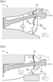
Fig. 1 in einer schematischen Schnittdarstellung in Draufsicht die erfindungsgemäße Kupplungsanordnung in einer ersten Position gemäß einer ersten Ausführungsform; -
Fig. 2 in einer schematischen Schnittdarstellung in Seitenansicht die erfindungsgemäße Kupplungsanordnung in der ersten Position gemäß der ersten Ausführungsform; -
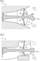
Fig. 3 in einer schematischen Schnittdarstellung in Draufsicht die erfindungsgemäße Kupplungsanordnung in einer zweiten Position gemäß der ersten Ausführungsform; -
Fig. 4 in einer schematischen Schnittdarstellung in Seitenansicht die erfindungsgemäße Kupplungsanordnung in der zweiten Position gemäß der ersten Ausführungsform; -
Fig. 5 in einer schematischen Schnittdarstellung in Draufsicht die erfindungsgemäße Kupplungsanordnung in einer ersten Position gemäß einer zweiten Ausführungsform; -
Fig. 6 in einer schematischen Schnittdarstellung in Seitenansicht die erfindungsgemäße Kupplungsanordnung in der ersten Position gemäß der zweiten Ausführungsform; -
Fig. 7 in einer schematischen Schnittdarstellung in Draufsicht die erfindungsgemäße Kupplungsanordnung in einer zweiten Position gemäß der zweiten Ausführungsform; -
Fig. 8 in einer schematischen Schnittdarstellung in Seitenansicht die erfindungsgemäße Kupplungsanordnung in der zweiten Position gemäß der zweiten Ausführungsform; -
Fig. 9 in einer schematischen Schnittdarstellung in Draufsicht die erfindungsgemäße Kupplungsanordnung in einer ersten Position gemäß einer dritten Ausführungsform; -
Fig. 10 in einer schematischen Schnittdarstellung in Seitenansicht die erfindungsgemäße Kupplungsanordnung in der ersten Position gemäß der dritten Ausführungsform; -
Fig. 11 in einer schematischen Schnittdarstellung in Draufsicht die erfindungsgemäße Kupplungsanordnung in einer zweiten Position gemäß der dritten Ausführungsform; und -
Fig. 12 in einer schematischen Schnittdarstellung in Seitenansicht die erfindungsgemäße Kupplungsanordnung in der zweiten Position gemäß der dritten Ausführungsform. -
Fig. 1 zeigt in einer schematischen Schnittdarstellung in Draufsicht undFig. 2 zeigt in einer schematischen Schnittdarstellung in Seitenansicht die erfindungsgemäße Kupplungsanordnung 10 in einer ersten Position P1 gemäß der ersten Ausführungsform. - Bei der ersten Position P1 handelt es sich um eine Kupplungsmittelstellung.
- Die Kupplungsanordnung 10 ist insbesondere die Kupplungsanordnung eines spurgeführten Fahrzeugs, vorzugsweise eines Schienenfahrzeugs zum Personentransport.
- Erfindungsgemäß wird ferner ein spurgeführtes Fahrzeug 1, vorzugsweise Schienenfahrzeug des Personentransports, bereitgestellt, umfassend zumindest eine Kupplungsanordnung 10.
- Die Kupplungsanordnung 10 umfasst eine Mittelpufferkupplung 100 und ein die Mittelpufferkupplung 100 umgebenes Kupplungsmaul 200.
- Das Kupplungsmaul 200 bildet dabei einen Hohlraum aus, in dem die Mittelpufferkupplung 100 angeordnet ist.
- Das Kupplungsmaul 200 weist eine Anschlusskontur 210 auf. Die Kupplungsanordnung 10 weist ferner ein flexibles Aerodynamikelement 300 zum aerodynamischen Verschließen des Kupplungsmauls 200 gegenüber der Mittelpufferkupplung 100 auf.
- Das flexible Aerodynamikelement 300 ist gegenüber der Anschlusskontur 210 des Kupplungsmauls 200 beweglich angeordnet. Im Fall der ersten Ausführungsform bedeutet dies, dass das flexible Aerodynamikelement 300 relativ zu der Anschlusskontur 210 des Kupplungsmauls 200 beweglich ist.
- Das flexible Aerodynamikelement 300 ist einseitig befestigt. Gemäß dem ersten Ausführungsbeispiel ist das flexible Aerodynamikelement 300 an der Mittelpufferkupplung 100 fixiert.
- Das flexible Aerodynamikelement 300 ist gemäß der ersten Ausführungsform an der Mittelpufferkupplung 100 fixiert und gegenüber der Anschlusskontur 210 des Kupplungsmauls 200 beweglich angeordnet.
- Das flexible Aerodynamikelement 300 weist eine Anbindung 310 auf. Gemäß erster Ausführungsform ist mittels der Anbindung 310 das flexible Aerodynamikelement 300 an der Mittelpufferkupplung 100 fixiert angeordnet.
- Das flexible Aerodynamikelement 300 weist zumindest eine erste Dichtfläche 320 auf.
- Gemäß der ersten Ausführungsform weist die Anschlusskontur 210 des Kupplungsmauls 200 zumindest eine zweite Dichtfläche 220 auf.
- Die zumindest eine erste Dichtfläche 320 und die zumindest eine zweite Dichtfläche 220 sind relativ zueinander beweglich angeordnet.
- Das flexible Aerodynamikelement 300 ist in Längsrichtung L der Kupplungsanordnung 10 näher an der Öffnung 230 des Kupplungsmauls 200 angeordnet, als die Anschlusskontur 210.
- Die zumindest eine erste Dichtfläche 320 ist in Längsrichtung L der Kupplungsanordnung 10 näher an der Öffnung 230 des Kupplungsmauls 200 angeordnet als die zumindest eine zweite Dichtfläche 220.
- Das Aerodynamikelement 300 ist als Regenschirm-Rückschlagventil ausgebildet.
- Wie aus der
Fig. 1 erkennbar ist, liegen in der ersten Position P1 (Kupplungsmittelstellung) die erste Dichtfläche 320 und die zweite Dichtfläche 220 derart aufeinander an, dass eine in das Kupplungsmaul 200 hinein gerichtete Luftströmung S das Aerodynamikelement 300 nicht passieren kann. -
Fig. 3 zeigt in einer schematischen Schnittdarstellung in Draufsicht undFig. 4 zeigt in einer schematischen Schnittdarstellung in Seitenansicht die erfindungsgemäße Kupplungsanordnung 10 in einer zweiten Position P2 gemäß der ersten Ausführungsform. - Die Kupplungsanordnung 10 ist zumindest in einer ersten Position P1, vorzugsweise einer Kupplungsmittelstellung (vgl.
-
Fig. 1 und 2 ), und in einer zweiten Position P2, vorzugsweise einer maximalen Auslenkungsposition (vgl.Fig. 3 und 4 ), anordnenbar. - Wie aus der
Fig. 3 und derFig. 4 in Zusammenschau mit denFig. 1 und 2 zu erkennen ist, ist das flexible Aerodynamikelement 300 gegenüber der der Anbindungskontur 210 des Kupplungsmauls 200 beweglich angeordnet. - Im Fall der ersten Ausführungsform kann die Mittelpufferkupplung 100 gegenüber dem flexible Aerodynamikelement 300 ausgelenkt werden.
- Gemäß der
Fig. 3 und 4 ist die Kupplungsanordnung 10 in einer maximalen Auslenkungsposition als zweite Position P2 angeordnet, wobei in der maximalen Auslenkungsposition P2 die Mittelpufferkupplung 100 maximal ausgelenkt ist. Vorzugsweise ist die Mittelpufferkupplung dazu in Höherichtung und in Querrichtung maximal ausgelenkt, wie inFig. 3 und 4 gezeigt. - In der ersten Position P1 (vgl.
Fig. 1 und 2 ) sind die erste Dichtfläche 320 und die zweite Dichtfläche 220 derart angeordnet, dass eine aus dem Kupplungsmaul 200 heraus gerichtete Luftströmung S das Aerodynamikelement 300 passieren kann (Strömung nicht gezeigt in den Figuren). - In der zweiten Position P2 (vgl.
Fig. 3 und 4 ) sind die erste Dichtfläche 320 und die zweite Dichtfläche 220 derart voneinander beabstandet, dass eine aus dem Kupplungsmaul 200 heraus gerichtete Luftströmung S das Aerodynamikelement 300 passieren kann. - Ferner sind in der zweiten Position P2 die erste Dichtfläche 320 und die zweite Dichtfläche 220 derart voneinander beabstandet, dass eine in das Kupplungsmaul 200 hinein gerichtete Luftströmung S das Aerodynamikelement 300 passieren kann.
- Das flexible Aerodynamikelement 300 ist derart bemessen, dass in der ersten Position P1, die gemäß
Fig. 1 und 2 eine Kupplungsmittelposition ist, die zumindest eine erste Dichtfläche 320 des flexiblen Aerodynamikelements 300 auf der zumindest einen zweiten Dichtfläche 220 aufliegt und in der zweiten Position P2, die vorzugsweise eine maximale Auslenkungsposition der Mittelpufferkupplung 100 ist, eine Lücke zwischen der zumindest eine ersten Dichtfläche 320 des flexiblen Aerodynamikelements 300 und der zumindest einen zweiten Dichtfläche 220 ausgebildet ist. - Das flexible Aerodynamikelement 300 umfasst als Material einen Kunststoff, insbesondere ein Elastomer und/oder ein textiles Material.
- Das flexible Aerodynamikelement 300 kann ferner ein die Biegesteifigkeit erhöhende Verstärkungselement aufweisen.
- Das flexible Aerodynamikelement 300 kann mehrere überlappende Elemente umfassen.
-
Fig. 5 zeigt in einer schematischen Schnittdarstellung in Draufsicht undFig. 6 zeigt in einer schematischen Schnittdarstellung in Seitenansicht die erfindungsgemäße Kupplungsanordnung 10 in einer ersten Position P1 gemäß einer zweiten Ausführungsform. -
Fig. 7 zeigt in einer schematischen Schnittdarstellung in Draufsicht undFig. 8 zeigt in einer schematischen Schnittdarstellung in Seitenansicht die erfindungsgemäße Kupplungsanordnung 10 in einer zweiten Position P2 gemäß der zweiten Ausführungsform. - Das zweite Ausführungsbeispiel beruht auf dem ersten Ausführungsbeispiel und nachfolgend sind lediglich die Unterschiede zwischen dem zweiten Ausführungsbeispiel und dem ersten Ausführungsbeispiel beschrieben. Zusätzlich sind zum besseren Verständnis ergänzend einige Passagen zu den
Figuren 5 bis 8 ergänzt, welche auch Übereinstimmungen mit der ersten Ausführungsform beschreiben. - Das flexible Aerodynamikelement 300 ist gegenüber der Mittelpufferkupplung 100 beweglich angeordnet. Im Fall der zweiten Ausführungsform bedeutet dies, dass die Mittelpufferkupplung 100 relativ zu dem flexible Aerodynamikelement 300 beweglich ist.
- Das flexible Aerodynamikelement 300 ist einseitig befestigt. Gemäß dem zweiten Ausführungsbeispiel ist das flexible Aerodynamikelement 300 an der Anschlusskontur 210 des Kupplungsmauls 200 fixiert.
- Das flexible Aerodynamikelement 300 ist gemäß der zweiten Ausführungsform an der Anschlusskontur 210 des Kupplungsmauls 200 fixiert und gegenüber der Mittelpufferkupplung 100 beweglich angeordnet.
- Das flexible Aerodynamikelement 300 weist eine Anbindung 310 auf. Gemäß der zweiten Ausführungsform ist das flexible Aerodynamikelement 300 mittels der Anbindung 310 an der Anschlusskontur 210 fixiert angeordnet.
- Das flexible Aerodynamikelement 300 weist zumindest eine erste Dichtfläche 320 auf.
- Gemäß der zweiten Ausführungsform weist die Mittelpufferkupplung 100 zumindest eine zweite Dichtfläche 120 auf.
- Die zumindest eine erste Dichtfläche 320 und die zumindest eine zweite Dichtfläche 120 sind relativ zueinander beweglich angeordnet.
- Das flexible Aerodynamikelement 300 ist in Längsrichtung L der Kupplungsanordnung 10 weiter weg von der Öffnung 230 des Kupplungsmauls 200 angeordnet als die Anschlusskontur 210 und fest an der Anschlusskontur 210 angebunden.
- Das flexible Aerodynamikelement 300 ist in Längsrichtung L der Kupplungsanordnung 10 näher an der Öffnung 230 des Kupplungsmauls 200 angeordnet als die zweite Dichtfläche 120 der Mittelpufferkupplung 100.
- Die zumindest eine erste Dichtfläche 320 ist in Längsrichtung L der Kupplungsanordnung 10 näher an der Öffnung 230 des Kupplungsmauls 200 angeordnet als die zumindest eine zweite Dichtfläche 120.
- Das Aerodynamikelement 300 ist als Regenschirm-Rückschlagventil ausgebildet.
- Wie aus der
Fig. 5 erkennbar ist, liegen in der ersten Position P1 (Kupplungsmittelstellung) die erste Dichtfläche 320 und die zweite Dichtfläche 220 derart aufeinander an, dass eine in das Kupplungsmaul 200 hinein gerichtete Luftströmung S das Aerodynamikelement 300 nicht passieren kann. - Die Kupplungsanordnung 10 ist gemäß der zweiten Ausführungsform zumindest in einer ersten Position P1, vorzugsweise Kupplungsmittelstellung (vgl.
Fig. 5 und 6 ) und in einer zweiten Position P2, vorzugsweise einer maximalen Auslenkungsposition, (vgl.Fig. 7 und 8 ) anordnenbar. - Wie aus der
Fig. 7 und derFig. 8 zu erkennen ist, ist das flexible Aerodynamikelement 300 gegenüber der Mittelpufferkupplung 100 beweglich angeordnet. - Im Fall der zweiten Ausführungsform kann die Mittelpufferkupplung 100 gegenüber dem flexible Aerodynamikelement 300 ausgelenkt werden.
- Gemäß der
Fig. 7 und 8 ist die Kupplungsanordnung 10 in einer zweiten Position, vorzugsweise einer maximalen - Auslenkungsposition P2 in der die Mittelpufferkupplung 100 maximal ausgelenkt ist, angeordnet. Vorzugsweise ist die Mittelpufferkupplung 100 dazu in Höherichtung und in Querrichtung maximal ausgelenkt, wie in
Fig. 7 und 8 gezeigt. - In der ersten Position P1, die vorzugsweise eine Kupplungsmittelposition ist, (vgl.
Fig. 7 und 8 ) sind die erste Dichtfläche 320 und die zweite Dichtfläche 120 derart angeordnet sind, dass eine aus dem Kupplungsmaul 200 heraus gerichtete Luftströmung S das Aerodynamikelement 300 passieren kann (Strömung nicht gezeigt in den Figuren). - In der zweiten Position P2, die vorzugsweise eine maximale Auslenkungsposition ist (vgl.
Fig. 7 und 8 ) sind die erste Dichtfläche 320 und die zweite Dichtfläche 120 derart voneinander beabstandet, dass eine aus dem Kupplungsmaul 200 heraus gerichtete Luftströmung S das Aerodynamikelement 300 passieren kann. - Ferner sind in der zweiten Position P2, die vorzugsweise eine maximale Auslenkungsposition ist, die erste Dichtfläche 320 und die zweite Dichtfläche 120 derart voneinander beabstandet, dass eine in das Kupplungsmaul 200 hinein gerichtete Luftströmung S das Aerodynamikelement 300 passieren kann.
- Das flexible Aerodynamikelement 300 ist auch gemäß der zweiten Ausführungsform derart bemessen, dass in der ersten Position P1, die vorzugsweise eine Kupplungsmittelposition ist, die zumindest eine erste Dichtfläche 320 des flexiblen Aerodynamikelements 300 auf der zumindest einen zweiten Dichtfläche 120 aufliegt und in der zweiten Position P2, die vorzugsweise eine maximale Auslenkungsposition der Mittelpufferkupplung 100 ist, eine Lücke zwischen der zumindest eine ersten Dichtfläche 320 des flexiblen Aerodynamikelements 300 und der zumindest einen zweiten Dichtfläche 120 ausgebildet ist.
-
Fig. 9 zeigt in einer schematischen Schnittdarstellung in Draufsicht undFig. 10 zeigt in einer schematischen Schnittdarstellung in Seitenansicht die erfindungsgemäße Kupplungsanordnung 10 in einer ersten Position P1 gemäß einer dritten Ausführungsform. -
Fig. 11 zeigt in einer schematischen Schnittdarstellung in Draufsicht undFig. 12 zeigt in einer schematischen Schnittdarstellung in Seitenansicht die erfindungsgemäße Kupplungsanordnung 10 in einer zweiten Position P2 gemäß der dritten Ausführungsform. - Das dritte Ausführungsbeispiel beruht dabei auf dem ersten Ausführungsbeispiel und nachfolgend sind lediglich die Unterschiede zwischen dem dritten Ausführungsbeispiel und dem ersten Ausführungsbeispiel beschrieben. Zusätzlich sind zum besseren Verständnis ergänzend einige Passagen zu den
Figuren 9 bis 11 ergänzt, welche auch Übereinstimmungen mit der ersten Ausführungsform beschreiben. - Gemäß der dritten Ausführungsform ist das flexible Aerodynamikelement 300 gegenüber der Anschlusskontur 210 des Kupplungsmauls 200 beweglich angeordnet ist und gegenüber der Mittelpufferkupplung 100 beweglich angeordnet ist.
- Im Fall der dritten Ausführungsform bedeutet dies, dass die Mittelpufferkupplung 100 relativ zu dem flexible Aerodynamikelement 300 beweglich ist und das flexible Aerodynamikelement 300 beweglich gegenüber der Anschlusskontur 210 ist.
- Das flexible Aerodynamikelement 300 weist mehrere erste Dichtflächen 320 auf.
- Gemäß der dritten Ausführungsform weist die Mittelpufferkupplung 100 zumindest eine zweite Dichtfläche 120, 220 auf.
- Die zumindest eine erste Dichtfläche 320 und die zumindest eine zweite Dichtfläche 120 der Mittelpufferkupplung 100 sind relativ zueinander beweglich angeordnet.
- Gemäß der dritten Ausführungsform weist ferner die Anschlusskontur 210 zumindest eine zweite Dichtfläche 220 auf.
- Die zumindest eine erste Dichtfläche 320 und die zumindest eine zweite Dichtfläche 120, 220 sind relativ zueinander beweglich angeordnet.
- Das flexible Aerodynamikelement 300 ist in Längsrichtung L der Kupplungsanordnung 10 näher an der Öffnung 230 des Kupplungsmauls 200 angeordnet als die zweite Dichtfläche 120, 220 der Mittelpufferkupplung 100.
- Das flexible Aerodynamikelement 300 ist in Längsrichtung L der Kupplungsanordnung 10 näher an der Öffnung 230 des Kupplungsmauls 200 angeordnet als die zweite Dichtfläche 120, 220 der Anschlusskontur 210.
- Die zumindest eine erste Dichtfläche 320 ist in Längsrichtung L der Kupplungsanordnung 10 näher an der Öffnung 230 des Kupplungsmauls 200 angeordnet als die zumindest eine zweite Dichtfläche 120, 220.
- Das Aerodynamikelement 300 ist als Regenschirm-Rückschlagventil ausgebildet.
- Wie aus der
Fig. 9 erkennbar ist, liegen in der ersten Position P1 (Kupplungsmittelstellung) die ersten Dichtflächen 320 und die zweiten Dichtflächen 120, 220 derart aufeinander an, dass eine in das Kupplungsmaul 200 hinein gerichtete Luftströmung S das Aerodynamikelement 300 nicht passieren kann. - Die Kupplungsanordnung 10 ist gemäß der dritten Ausführungsform zumindest in einer ersten Position P1, vorzugsweise Kupplungsmittelstellung (vgl.
Fig. 9 und 10 ) und in einer zweiten Position P2, vorzugsweise einer maximalen Auslenkungsposition, (vgl.Fig. 11 und 12 ) anordnenbar. - Wie aus der
Fig. 11 und derFig. 12 zu erkennen ist, ist das flexible Aerodynamikelement 300 gegenüber der Mittelpufferkupplung 100 beweglich angeordnet. - Im Fall der zweiten Ausführungsform kann die Mittelpufferkupplung 100 gegenüber dem flexible Aerodynamikelement 300 ausgelenkt werden.
- Gemäß der
Fig. 11 und 12 ist die Kupplungsanordnung 10 in einer zweiten Position, vorzugsweise einer maximalen Auslenkungsposition P2 in der die Mittelpufferkupplung 100 maximal ausgelenkt ist, angeordnet. Vorzugsweise ist die Mittelpufferkupplung 100 dazu in Höherichtung und in Querrichtung maximal ausgelenkt, wie inFig. 11 und 12 gezeigt. - In der ersten Position P1, die vorzugsweise eine Kupplungsmittelposition ist, (vgl.
Fig. 9 und 10 ) sind die ersten Dichtflächen 320 und die zweiten Dichtflächen 220 derart angeordnet, dass eine aus dem Kupplungsmaul 200 heraus gerichtete Luftströmung S das Aerodynamikelement 300 passieren kann (Strömung nicht gezeigt in den Figuren). - In der zweiten Position P2, die vorzugsweise eine maximale Auslenkungsposition ist (vgl.
Fig. 7 und 8 ), sind die ersten Dichtflächen 320 und die zweiten Dichtflächen 220 derart voneinander beabstandet, dass eine aus dem Kupplungsmaul 200 heraus gerichtete Luftströmung S das Aerodynamikelement 300 passieren kann. - Ferner sind in der zweiten Position P2, die vorzugsweise eine maximale Auslenkungsposition ist, die ersten Dichtflächen 320 und die zweiten Dichtflächen 220 derart voneinander beabstandet, dass eine in das Kupplungsmaul 200 hinein gerichtete Luftströmung S das Aerodynamikelement 300 passieren kann.
- Das flexible Aerodynamikelement 300 ist auch gemäß der dritten Ausführungsform derart bemessen, dass in der ersten Position P1, die vorzugsweise eine Kupplungsmittelposition ist, die ersten Dichtflächen 320 des flexiblen Aerodynamikelements 300 auf den zweiten Dichtflächen 120, 220 aufliegen und in der zweiten Position P2, die vorzugsweise eine maximale Auslenkungsposition der Mittelpufferkupplung 100 ist, eine Lücke zwischen der zumindest eine ersten Dichtfläche 320 des flexiblen Aerodynamikelements 300 und der zumindest einen zweiten Dichtfläche 120, 220 ausgebildet ist.
- Es kann vorgesehen sein, dass Seile und/oder Federn ausgebildet sind, die das flexiblen Aerodynamikelement 300 in Sollposition halten.
- Die vorstehende Offenbarung gilt gleichermaßen wie für die Kupplungsanordnung 10 auch für das spurgeführtes Fahrzeug des Personentransports, umfassend zumindest eine wie vorstehend beschrieben ausgeführte Kupplungsanordnung 10.
- Bei dem spurgeführten Fahrzeug 1 handelt es sich vorzugsweise um ein Schienenfahrzeug.
- Abschließend sei erwähnt, dass die Merkmale aller oben beschriebenen Ausführungsvarianten untereinander in beliebiger Weise kombiniert werden können, um weitere andere Ausführungsbeispiele der Erfindung zu bilden. Auch können alle Merkmale von Unteransprüchen jeweils für sich mit jedem Merkmal jedes anderen der Ansprüche kombiniert werden, und zwar jeweils für sich allein oder in beliebiger Kombination, um weitere andere Ausführungsbeispiele zu erhalten.
- Obwohl die Erfindung im Detail durch ein Ausführungsbeispiel näher illustriert und beschrieben wurde, so ist die Erfindung nicht durch die offenbarten Beispiele eingeschränkt und andere Variationen können vom Fachmann hieraus abgeleitet werden, ohne den Schutzumfang der Erfindung zu verlassen.
- Unabhängig vom grammatikalischen Geschlecht eines bestimmten Begriffes sind Personen mit männlicher, weiblicher oder anderer Geschlechteridentität mit umfasst.
Claims (16)
- Kupplungsanordnung (10), insbesondere eines spurgeführten Fahrzeugs des Personentransport, umfassend eine Mittelpufferkupplung (100),ein die Mittelpufferkupplung (100) umgebenes Kupplungsmaul (200) mit einer Anschlusskontur (210) undein flexibles Aerodynamikelement (300) zum aerodynamischen Verschließen des Kupplungsmauls (200) gegenüber der Mittelpufferkupplung (100),dadurch gekennzeichnet, dassdas flexible Aerodynamikelement (300) gegenüber der Mittelpufferkupplung (100) und/oder gegenüber der Anschlusskontur (210) des Kupplungsmauls (200) beweglich angeordnet ist.
- Kupplungsanordnung (10) nach Anspruch 1, dadurch gekennzeichnet, dass das flexible Aerodynamikelement (300) einseitig entweder an der Mittelpufferkupplung (100) oder an der Anschlusskontur (210) des Kupplungsmaul (200) fixiert ist.
- Kupplungsanordnung (10) nach Anspruch 1 oder 2, dadurch gekennzeichnet, dassdas flexible Aerodynamikelement (300) an der Mittelpufferkupplung (100) fixiert ist und gegenüber an der Anschlusskontur (210) des Kupplungsmauls (200) beweglich angeordnet ist, oderdas flexible Aerodynamikelement (300) an der Anschlusskontur (210) des Kupplungsmauls (200) fixiert ist und gegenüber der Mittelpufferkupplung (100) beweglich angeordnet ist, oderdas flexible Aerodynamikelement (300) gegenüber der Anschlusskontur (210) des Kupplungsmauls (200) beweglich angeordnet ist und gegenüber der Mittelpufferkupplung (100) beweglich angeordnet ist.
- Kupplungsanordnung (10) nach eine der vorhergehenden Ansprüche, dadurch gekennzeichnet, dass das flexible Aerodynamikelement (300) eine Anbindung (310) aufweist, mittels der das flexible Aerodynamikelement (300) an der an der Anschlusskontur (210) des Kupplungsmauls (200) oder der Mittelpufferkupplung (100) fixiert angeordnet ist.
- Kupplungsanordnung (10) nach eine der vorhergehenden Ansprüche, dadurch gekennzeichnet, dass das flexible Aerodynamikelement (300) zumindest eine erste Dichtfläche (320) aufweist und die Anschlusskontur (210) des Kupplungsmauls und/oder der die Mittelpufferkupplung (100) zumindest eine zweite Dichtfläche (120, 220) aufweist, wobei die zumindest eine erste Dichtfläche (320) und die zumindest eine zweite Dichtfläche (120, 220) relativ zueinander beweglich angeordnet sind.
- Kupplungsanordnung (10) nach eine der vorhergehenden Ansprüche, dadurch gekennzeichnet, dass die Kupplungsanordnung (10) zumindest in einer ersten Position(P1), vorzugsweise einer Kupplungsmittelstellung und in einer zweiten Position (P2) anordnenbar ist.
- Kupplungsanordnung (10) nach Anspruch 7 oder 8, dadurch gekennzeichnet, dass die zumindest eine erste Dichtfläche (320) in Längsrichtung (L) der Kupplungsanordnung (10) näher an der Öffnung (230) des Kupplungsmauls (200) angeordnet ist als die zumindest eine zweite Dichtfläche (120, 220).
- Kupplungsanordnung (10) nach einem der vorhergehenden Ansprüche, dadurch gekennzeichnet, dass dadurch gekennzeichnet, dass das Aerodynamikelement (300) als Regenschirm-Rückschlagventil ausgebildet ist.
- Kupplungsanordnung (10) nach einem der Ansprüche 7 bis 10, dadurch gekennzeichnet, dass dadurch gekennzeichnet, dass in der ersten Position (P1) die zumindest eine erste Dichtfläche (320) und die zumindest eine zweite Dichtfläche (120, 220) derart aufeinander aufliegen, dass eine in das Kupplungsmaul (200) hinein gerichtete Luftströmung (S) das flexible Aerodynamikelement (300) nicht passieren kann.
- Kupplungsanordnung (10) nach Anspruch 8 bis 11, dadurch gekennzeichnet, dass in der ersten Position (P1) die zumindest eine erste Dichtfläche (320) und die zumindest eine zweite Dichtfläche (120, 220) derart angeordnet sind, dass eine aus dem Kupplungsmaul (200) heraus gerichtete Luftströmung (S) das flexible Aerodynamikelement (300) passieren kann.
- Kupplungsanordnung (10) nach einem der Ansprüche 8 bis 12, dadurch gekennzeichnet, dass in der Kupplungsmittelstellung (P2) die zumindest eine erste Dichtfläche (320) und die zumindest eine zweite Dichtfläche (120, 220) derart voneinander beabstandet sind, dass eine aus dem Kupplungsmaul (200) heraus gerichtete Luftströmung (S) das Aerodynamikelement (300) passieren kann, und dass eine in das Kupplungsmaul (200) hinein gerichtete Luftströmung (S) das Aerodynamikelement (300) passieren kann.
- Kupplungsanordnung (10) nach einem der Ansprüche 8 bis 13, dadurch gekennzeichnet, dass das flexible Aerodynamikelement (300) derart bemessen ist, dass in der ersten Position (P1), vorzugsweise in Kupplungsmittelposition, die zumindest eine erste Dichtfläche des flexible Aerodynamikelements (300) auf der zumindest einen zweiten Dichtfläche (120, 220) aufliegt und in der ersten Position (P1), die vorzugsweise eine maximaler Auslenkungsposition der Mittelpufferkupplung (100) entspricht, eine Lücke zwischen der zumindest eine ersten Dichtfläche des flexiblen Aerodynamikelements (300) und der zumindest einen zweiten Dichtfläche (120,220) ausgebildet ist.
- Kupplungsanordnung (10) nach einem der vorhergehenden Ansprüche, dadurch gekennzeichnet, dass das flexible Aerodynamikelement (300) als Material einen Kunststoff, insbesondere ein Elastomer und/oder ein textiles Material umfasst.
- Kupplungsanordnung (10) nach einem der vorhergehenden Ansprüche, dadurch gekennzeichnet, dass das flexible Aerodynamikelement (300) die Biegesteifigkeit erhöhende Verstärkungselement aufweist.
- Kupplungsanordnung (10) nach einem der vorhergehenden Ansprüche, dadurch gekennzeichnet, dass das flexible Aerodynamikelement (300) mehrere überlappende Elemente umfasst.
- Spurgeführtes Fahrzeug (1), vorzugsweise Schienenfahrzeug des Personentransports, umfassend zumindest einen Wagen (10) nach einem der Ansprüche 1 bis 15.
Applications Claiming Priority (1)
| Application Number | Priority Date | Filing Date | Title |
|---|---|---|---|
| DE102023209621.8A DE102023209621A1 (de) | 2023-09-29 | 2023-09-29 | Kupplungsanordnung und spurgeführtes Fahrzeug |
Publications (1)
| Publication Number | Publication Date |
|---|---|
| EP4530146A1 true EP4530146A1 (de) | 2025-04-02 |
Family
ID=92538933
Family Applications (1)
| Application Number | Title | Priority Date | Filing Date |
|---|---|---|---|
| EP24196050.9A Pending EP4530146A1 (de) | 2023-09-29 | 2024-08-23 | Kupplungsanordnung und spurgeführtes fahrzeug |
Country Status (2)
| Country | Link |
|---|---|
| EP (1) | EP4530146A1 (de) |
| DE (1) | DE102023209621A1 (de) |
Citations (4)
| Publication number | Priority date | Publication date | Assignee | Title |
|---|---|---|---|---|
| EP2177416A1 (de) * | 2008-08-04 | 2010-04-21 | Alstom Transport S.A. | Schienenfahrzeug |
| EP2524850A1 (de) * | 2011-05-20 | 2012-11-21 | Voith Patent GmbH | Vorrichtung zum bedarfsweisen Abdichten einer im Stirnbereich eines spurgeführten Fahrzeuges vorgesehenen Öffnung, Bugnasenmodul mit einer derartigen Vorrichtung und spurgeführtes Fahrzeug mit einem derartigen Bugnasenmodul |
| EP3523171B1 (de) * | 2016-10-05 | 2020-06-10 | Voith Patent GmbH | Schienenfahrzeugbug |
| CN115871733A (zh) * | 2022-12-02 | 2023-03-31 | 中车南京浦镇车辆有限公司 | 一种轨道车辆车头开闭装置 |
Family Cites Families (2)
| Publication number | Priority date | Publication date | Assignee | Title |
|---|---|---|---|---|
| DE29615191U1 (de) * | 1996-08-31 | 1997-09-25 | Linke-Hofmann-Busch GmbH, 38239 Salzgitter | Horizontal verschwenkbare Abdeckung für eine Durchtrittsöffnung in einer Stirnseite eines Schienenfahrzeuges für eine Mittelpufferkupplung |
| DE102018111979A1 (de) * | 2018-05-18 | 2019-11-21 | Voith Patent Gmbh | Kupplungsvorrichtung mit einer Abdeckeinrichtung und Schienenfahrzeug mit einer Kupplungsvorrichtung |
-
2023
- 2023-09-29 DE DE102023209621.8A patent/DE102023209621A1/de active Pending
-
2024
- 2024-08-23 EP EP24196050.9A patent/EP4530146A1/de active Pending
Patent Citations (4)
| Publication number | Priority date | Publication date | Assignee | Title |
|---|---|---|---|---|
| EP2177416A1 (de) * | 2008-08-04 | 2010-04-21 | Alstom Transport S.A. | Schienenfahrzeug |
| EP2524850A1 (de) * | 2011-05-20 | 2012-11-21 | Voith Patent GmbH | Vorrichtung zum bedarfsweisen Abdichten einer im Stirnbereich eines spurgeführten Fahrzeuges vorgesehenen Öffnung, Bugnasenmodul mit einer derartigen Vorrichtung und spurgeführtes Fahrzeug mit einem derartigen Bugnasenmodul |
| EP3523171B1 (de) * | 2016-10-05 | 2020-06-10 | Voith Patent GmbH | Schienenfahrzeugbug |
| CN115871733A (zh) * | 2022-12-02 | 2023-03-31 | 中车南京浦镇车辆有限公司 | 一种轨道车辆车头开闭装置 |
Also Published As
| Publication number | Publication date |
|---|---|
| DE102023209621A1 (de) | 2025-04-03 |
Similar Documents
| Publication | Publication Date | Title |
|---|---|---|
| EP3523171B1 (de) | Schienenfahrzeugbug | |
| DE102023209621A1 (de) | Kupplungsanordnung und spurgeführtes Fahrzeug | |
| DE9304251U1 (de) | Stromabnehmer | |
| DE29511921U1 (de) | Führungseinrichtung für schienengebundene Fahrzeuge (II) | |
| DE102008058242A1 (de) | Schiebetüranordnung | |
| DE102008008214A1 (de) | Eisenbahn-Kuppelstange mit Richtgelenken | |
| EP4229262B1 (de) | Türsystem mit linearführung ohne führungsschiene | |
| EP4186771B1 (de) | Fahrzeug umfassend einen balg mit entwässerungskanal | |
| DE3736217A1 (de) | Anordnung zum kontrollierten fuehren einer radachse bzw. eines drehgestells eines eine weiche durchfahrenden schienenfahrzeuges | |
| EP3313707A1 (de) | Antrieb für ein spurgeführtes fahrzeug | |
| EP0202483B2 (de) | Bauelement für Übergangsschutzeinrichtungen für gelenkig miteinander zu kuppelnde Fahrzeuge, insbesondere Schienenfahrzeuge | |
| DE102019101292A1 (de) | Luftleitvorrichtung und Kraftfahrzeug | |
| DE102016216719A1 (de) | Querweiches Einfachgelenk mit angenäherter Geradführung mittels Deichsel | |
| DE102020135039A1 (de) | Schweberahmen für ein fahrbahngebundenes Schwebefahrzeug einer Magnetschwebebahn | |
| DE102020106225A1 (de) | Spur-bzw. schienengeführtes Fahrzeug mit fortschrittlicher Aerodynamik | |
| DE4393389C1 (de) | Herzstückbereich | |
| WO2020244871A1 (de) | Triebzug zur personenbeförderung mit wankabstützung | |
| DE102006054818A1 (de) | Trägerelement, Lageranordnung und Einstellanordnung für eine Biegeweichenanordnung | |
| DE102007062377B4 (de) | Schienenfahrzeug mit schlankem Zugkopf | |
| DE102024200614A1 (de) | Bugklappenmodul | |
| AT517181B1 (de) | Aerodynamisches Hilfsmittel für ein Schienenfahrzeug | |
| EP3655302B1 (de) | Türdichtung für ein schienenfahrzeug | |
| EP4588750A1 (de) | Querführungsanordnung | |
| DE7710838U1 (de) | Eisenbahnwagen | |
| DE102005031598B4 (de) | Hochleistungsrichtgelenk |
Legal Events
| Date | Code | Title | Description |
|---|---|---|---|
| PUAI | Public reference made under article 153(3) epc to a published international application that has entered the european phase |
Free format text: ORIGINAL CODE: 0009012 |
|
| STAA | Information on the status of an ep patent application or granted ep patent |
Free format text: STATUS: THE APPLICATION HAS BEEN PUBLISHED |
|
| AK | Designated contracting states |
Kind code of ref document: A1 Designated state(s): AL AT BE BG CH CY CZ DE DK EE ES FI FR GB GR HR HU IE IS IT LI LT LU LV MC ME MK MT NL NO PL PT RO RS SE SI SK SM TR |
|
| STAA | Information on the status of an ep patent application or granted ep patent |
Free format text: STATUS: REQUEST FOR EXAMINATION WAS MADE |
|
| RAP3 | Party data changed (applicant data changed or rights of an application transferred) |
Owner name: SIEMENS MOBILITY GMBH |
|
| 17P | Request for examination filed |
Effective date: 20250929 |