EP4530001A1 - Stanzhülse - Google Patents
Stanzhülse Download PDFInfo
- Publication number
- EP4530001A1 EP4530001A1 EP23200731.0A EP23200731A EP4530001A1 EP 4530001 A1 EP4530001 A1 EP 4530001A1 EP 23200731 A EP23200731 A EP 23200731A EP 4530001 A1 EP4530001 A1 EP 4530001A1
- Authority
- EP
- European Patent Office
- Prior art keywords
- weight percent
- punch sleeve
- titanium
- punch
- sleeve
- Prior art date
- Legal status (The legal status is an assumption and is not a legal conclusion. Google has not performed a legal analysis and makes no representation as to the accuracy of the status listed.)
- Withdrawn
Links
Images

Classifications
-
- C—CHEMISTRY; METALLURGY
- C22—METALLURGY; FERROUS OR NON-FERROUS ALLOYS; TREATMENT OF ALLOYS OR NON-FERROUS METALS
- C22C—ALLOYS
- C22C29/00—Alloys based on carbides, oxides, nitrides, borides, or silicides, e.g. cermets, or other metal compounds, e.g. oxynitrides, sulfides
- C22C29/02—Alloys based on carbides, oxides, nitrides, borides, or silicides, e.g. cermets, or other metal compounds, e.g. oxynitrides, sulfides based on carbides or carbonitrides
- C22C29/06—Alloys based on carbides, oxides, nitrides, borides, or silicides, e.g. cermets, or other metal compounds, e.g. oxynitrides, sulfides based on carbides or carbonitrides based on carbides, but not containing other metal compounds
- C22C29/10—Alloys based on carbides, oxides, nitrides, borides, or silicides, e.g. cermets, or other metal compounds, e.g. oxynitrides, sulfides based on carbides or carbonitrides based on carbides, but not containing other metal compounds based on titanium carbide
-
- B—PERFORMING OPERATIONS; TRANSPORTING
- B21—MECHANICAL METAL-WORKING WITHOUT ESSENTIALLY REMOVING MATERIAL; PUNCHING METAL
- B21D—WORKING OR PROCESSING OF SHEET METAL OR METAL TUBES, RODS OR PROFILES WITHOUT ESSENTIALLY REMOVING MATERIAL; PUNCHING METAL
- B21D51/00—Making hollow objects
- B21D51/16—Making hollow objects characterised by the use of the objects
- B21D51/26—Making hollow objects characterised by the use of the objects cans or tins; Closing same in a permanent manner
- B21D51/2669—Transforming the shape of formed can bodies; Forming can bodies from flattened tubular blanks; Flattening can bodies
-
- B—PERFORMING OPERATIONS; TRANSPORTING
- B22—CASTING; POWDER METALLURGY
- B22F—WORKING METALLIC POWDER; MANUFACTURE OF ARTICLES FROM METALLIC POWDER; MAKING METALLIC POWDER; APPARATUS OR DEVICES SPECIALLY ADAPTED FOR METALLIC POWDER
- B22F5/00—Manufacture of workpieces or articles from metallic powder characterised by the special shape of the product
- B22F5/10—Manufacture of workpieces or articles from metallic powder characterised by the special shape of the product of articles with cavities or holes, not otherwise provided for in the preceding subgroups
- B22F5/106—Tube or ring forms
-
- C—CHEMISTRY; METALLURGY
- C22—METALLURGY; FERROUS OR NON-FERROUS ALLOYS; TREATMENT OF ALLOYS OR NON-FERROUS METALS
- C22C—ALLOYS
- C22C1/00—Making non-ferrous alloys
- C22C1/04—Making non-ferrous alloys by powder metallurgy
- C22C1/05—Mixtures of metal powder with non-metallic powder
- C22C1/051—Making hard metals based on borides, carbides, nitrides, oxides or silicides; Preparation of the powder mixture used as the starting material therefor
-
- C—CHEMISTRY; METALLURGY
- C22—METALLURGY; FERROUS OR NON-FERROUS ALLOYS; TREATMENT OF ALLOYS OR NON-FERROUS METALS
- C22C—ALLOYS
- C22C29/00—Alloys based on carbides, oxides, nitrides, borides, or silicides, e.g. cermets, or other metal compounds, e.g. oxynitrides, sulfides
- C22C29/02—Alloys based on carbides, oxides, nitrides, borides, or silicides, e.g. cermets, or other metal compounds, e.g. oxynitrides, sulfides based on carbides or carbonitrides
- C22C29/04—Alloys based on carbides, oxides, nitrides, borides, or silicides, e.g. cermets, or other metal compounds, e.g. oxynitrides, sulfides based on carbides or carbonitrides based on carbonitrides
-
- C—CHEMISTRY; METALLURGY
- C22—METALLURGY; FERROUS OR NON-FERROUS ALLOYS; TREATMENT OF ALLOYS OR NON-FERROUS METALS
- C22C—ALLOYS
- C22C29/00—Alloys based on carbides, oxides, nitrides, borides, or silicides, e.g. cermets, or other metal compounds, e.g. oxynitrides, sulfides
- C22C29/16—Alloys based on carbides, oxides, nitrides, borides, or silicides, e.g. cermets, or other metal compounds, e.g. oxynitrides, sulfides based on nitrides
-
- B—PERFORMING OPERATIONS; TRANSPORTING
- B21—MECHANICAL METAL-WORKING WITHOUT ESSENTIALLY REMOVING MATERIAL; PUNCHING METAL
- B21D—WORKING OR PROCESSING OF SHEET METAL OR METAL TUBES, RODS OR PROFILES WITHOUT ESSENTIALLY REMOVING MATERIAL; PUNCHING METAL
- B21D37/00—Tools as parts of machines covered by this subclass
- B21D37/01—Selection of materials
-
- C—CHEMISTRY; METALLURGY
- C22—METALLURGY; FERROUS OR NON-FERROUS ALLOYS; TREATMENT OF ALLOYS OR NON-FERROUS METALS
- C22C—ALLOYS
- C22C29/00—Alloys based on carbides, oxides, nitrides, borides, or silicides, e.g. cermets, or other metal compounds, e.g. oxynitrides, sulfides
- C22C29/005—Alloys based on carbides, oxides, nitrides, borides, or silicides, e.g. cermets, or other metal compounds, e.g. oxynitrides, sulfides comprising a particular metallic binder
-
- C—CHEMISTRY; METALLURGY
- C22—METALLURGY; FERROUS OR NON-FERROUS ALLOYS; TREATMENT OF ALLOYS OR NON-FERROUS METALS
- C22C—ALLOYS
- C22C29/00—Alloys based on carbides, oxides, nitrides, borides, or silicides, e.g. cermets, or other metal compounds, e.g. oxynitrides, sulfides
- C22C29/02—Alloys based on carbides, oxides, nitrides, borides, or silicides, e.g. cermets, or other metal compounds, e.g. oxynitrides, sulfides based on carbides or carbonitrides
- C22C29/06—Alloys based on carbides, oxides, nitrides, borides, or silicides, e.g. cermets, or other metal compounds, e.g. oxynitrides, sulfides based on carbides or carbonitrides based on carbides, but not containing other metal compounds
- C22C29/067—Alloys based on carbides, oxides, nitrides, borides, or silicides, e.g. cermets, or other metal compounds, e.g. oxynitrides, sulfides based on carbides or carbonitrides based on carbides, but not containing other metal compounds comprising a particular metallic binder
Definitions
- the present invention relates to a punch sleeve, a punch apparatus, a use of said punch sleeve and a method for drawing a metal blank into a can body.
- EP 2 746 413 A1 shows a punch for manufacturing of metal beverage.
- a typical process for manufacturing beverage cans starts typically by cutting a circular metal blank out of a sheet of metal, typically made from an aluminium alloy or steel. Then the metal blank is typically placed into a cupping press, where the blank is drawn into the shape of a cup. Subsequently a punch sleeve, mounted onto a ram thereby forming a punch, is pushed swiftly, typically within a fraction of a second, and typically continuously against the then cup shaped metal blank through typically a drawing die and typically several ironing dies. The cup shaped metal blank is thus deep drawn, i.e., reduced in diameter and increased in height, and subsequently ironed, i.e., foremost increased further in height by stretching and thinning cup walls, creating a beverage can body. These two steps are typically called drawing and ironing.
- the objective of the present invention is to provide a punch sleeve which can increase productivity and decrease downtimes and energy consumption during manufacturing of beverage cans.
- the punch sleeve is made from a sintered material which comprises the following components: 10 to 35 weight percent tungsten carbide, 50 to 60 weight percent in total of one or more selected from titanium carbide, titanium carbonitride and titanium nitride, 35 to 5 weight percent in total of one or more selected from cobalt and nickel, 1.5 to 0 weight percent chromium, 2.5 to 0 weight percent molybdenum, 1 to 0 weight percent in total of other additions, wherein the sum in weight percentages of said components is 95 to 100 weight percent.
- weight precent and the like is to be understood throughout the present disclosure, unless stated otherwise, as the weight precent and the like of any of said components and optionally further components of the sintered material in relation to the total weight of the sintered material.
- a sum S1 (said tungsten carbide + said titanium carbide + said titanium carbonitride + said titanium nitride) in weight percentages can range from 60 to 95 weight percent
- a sum S2 (said cobalt + said nickel) in weight percentages can range from 35 to 5 weight percent
- said sintered material is essentially or completely free of said titanium nitride, i.e., that said titanium carbide and/or said titanium carbonitride is/are present, essentially without or without said titanium nitride, respectively.
- "in total of one or more selected from titanium carbide, titanium carbonitride and titanium nitride” is then replaced by "in total of one or more selected from titanium carbide and titanium carbonitride” regarding the definition of the composition of the sintered material.
- the punch sleeve is a sleeve, it can be slid and thereby mounted onto a ram, preferably by a nut screwed onto a threaded part of said ram such that said nut abuts an axial forward facing shoulder of the punch sleeve under radial clearance to the punch sleeve.
- the punch sleeve is a hollow and open-ended body, preferably open ended at both ends sides.
- the punch sleeve can be a one-piece body or a two or more-piece body. The punch sleeve helps distribute forces more evenly and can be replaced and maintained better over a monolithic ram used for direct punching.
- the punch sleeve is made from the sintered material comprising said following components: 10 to 35 weight percent tungsten carbide, 50 to 60 weight percent in total of one or more selected from titanium carbide, titanium carbonitride and titanium nitride, 35 to 5 weight percent in total of one or more selected from cobalt and nickel, 1.5 to 0 weight percent chromium, 2.5 to 0 weight percent molybdenum, 1 to 0 weight percent in total of other additions, wherein the sum in weight percentages of said components is 95 to 100 weight percent.
- the optimum balance between titanium carbide, titanium nitride and/or titanium carbonitride for weight reduction on the one side and tungsten carbide on the other side for wear resistance has been found combined with an optimum binder content, formed by said cobalt and/or nickel for toughness improvement; said titanium carbide, titanium nitride and/or titanium carbonitride have each a relatively low mass density of on average about 5 g/cm 3 , whereas the mass density of tungsten carbide is about 15.6 g/cm 3 and thus is on a volume basis heavier; the invention is not bound to any peculiarities related to the precise calculation of these densities.
- Said weight reduction is achieved by the relatively large total content in relatively low mass density of titanium carbide, titanium nitride and/or titanium carbonitride, enabled for by the presence of at least said relatively heavy tungsten carbide and said toughness enhancing cobalt and/or nickel. Due to said weight reduction, implemented by said composition of the sintered material, the punch sleeve can put less stress on the entire punch-die-system, expanding the lifespan of the die and other parts of related equipment as well, lowers operating costs, since less energy is required to move the punch sleeve, which is especially advantageous for high volume beverage can production operations, enhance precision during punching, and improve operator safety, since a lighter punch sleeve is easier to handle.
- Said sintered material has a microstructure formed predominantly by grains made from said titanium carbide, titanium nitride and/or titanium carbonitride, depending on which of these components is present, due to their relatively low mass density, i.e., high specific volume, in comparison to a higher mass density of said tungsten carbide.
- the tungsten carbide has typically a stoichiometry of WC.
- Titanium carbide if present, has typically a stochiometric composition of (Ti 1-r , W r )C, wherein r ranges from 0 to smaller 0.5, preferably from 0 to 0.15, i.e., some tungsten can be present in said titanium carbide.
- Titanium carbonitride if present, has typically a stochiometric composition of (Ti 1-x ,W x )(C 1-y ,N y ), wherein x ranges from 0 to smaller 0.5, preferably from 0 to 0.15, and y ranges from greater 0 to smaller 1, i.e., some tungsten can be present in said titanium carbonitride.
- Titanium nitride if present, has typically a stoichiometry of TiN.
- individual "titanium carbide grains” and “titanium carbonitride grains” can be identified in the microstructure of the sintered material, typically by EBSD (electron back-scatter diffraction) images, where said "titanium carbide grains” typically appear as almost black grains and said “titanium carbonitride grains” appear in a brighter, grey shading, typically larger in size on average than said "titanium carbide grains”.
- EBSD electron back-scatter diffraction
- the source for said molybdenum can typically be molybdenum powder and/or molybdenum carbide powder added to a powder mixture which can be pressed and sintered to manufacture said sintered material.
- the source for said chromium can typically be chromium powder and/or chromium carbide powder added to a powder mixture which can be pressed and sintered to manufacture said sintered material.
- said sintered material consists of said following components: 10 to 35 weight percent tungsten carbide, 50 to 60 weight percent in total of one or more selected from titanium carbide, titanium carbonitride and titanium nitride, 35 to 5 weight percent in total of one or more selected from cobalt and nickel, 1.5 to 0 weight percent chromium, 2.5 to 0 weight percent molybdenum, 1 to 0 weight percent in total of other additions, wherein the sum in weight percentages of said components is 100 weight percent.
- said sintered material consists of said following components: 10 to 35 weight percent tungsten carbide, 50 to 60 weight percent in total of one or more selected from titanium carbide, titanium carbonitride and titanium nitride, 35 to 5 weight percent in total of cobalt and nickel, wherein the content in cobalt is larger than 0 weight percent, wherein the content in nickel is larger than 0 weight percent, 1.5 to 0 weight percent chromium, 2.5 to 0 weight percent molybdenum, 1 to 0 weight percent in total of other additions, wherein the sum in weight percentages of said components is 100 weight percent.
- the composition of the sintered material comprises then cobalt and nickel.
- said sintered material consists of said following components: 10 to 35 weight percent tungsten carbide, 50 to 60 weight percent in total of one or more selected from titanium carbide and titanium carbonitride, 35 to 5 weight percent in total of one or more selected from cobalt and nickel, 1.5 to 0 weight percent chromium, 2.5 to 0 weight percent molybdenum, 1 to 0 weight percent in total of other additions, wherein the sum in weight percentages of said components is 100 weight percent.
- the composition of the sintered material is then free of titanium nitride.
- said sintered material consists of said following components: 10 to 35 weight percent tungsten carbide, 50 to 60 weight percent in total of one or more selected from titanium carbide and titanium carbonitride, 35 to 5 weight percent in total of cobalt and nickel, wherein the content in cobalt is larger than 0 weight percent, wherein the content in nickel is larger than 0 weight percent, 1.5 to 0 weight percent chromium, 2.5 to 0 weight percent molybdenum, 1 to 0 weight percent in total of other additions, wherein the sum in weight percentages of said components is 100 weight percent.
- the composition of the sintered material is then free of titanium nitride and comprises cobalt and nickel.
- the content in total of the one or more selected from titanium carbide, titanium carbonitride and titanium nitride is 52 to 56 weight percent. It has been found that within this narrower range of the titanium carbide, titanium carbonitride and titanium nitride, which can be used to replace any broader range of the titanium carbide, titanium carbonitride and/or titanium nitride in the present disclosure where the sintered material comprises or consists of said components, the punch sleeve has an improved tool lifetime, including the cases where the composition of the sintered material is free of titanium nitride.
- the tungsten carbide content is 27 to 33 weight percent. It has been found that within this narrower range of the tungsten carbide, which can be used to replace any broader range of the tungsten carbide in the present disclosure where the sintered material comprises or consists of said components, the punch sleeve has an improved tool lifetime, including the cases where the composition of the sintered material is free of titanium nitride.
- the nickel content is 1 to 6 weight percent. It has been found that when the nickel content is in the range from 1 to 6 weight percent, which can be used to replace any broader range of nickel in the present disclosure where the sintered material comprises or consists of said components, the punch sleeve has an improved tool lifetime, including the cases where the composition of the sintered material is free of titanium nitride; the nickel has been found to improve at least corrosion resistance.
- the nickel content is 2 to 4 weight percent. It has been found that when the nickel content is in the narrower range from 2 to 4 weight percent, which can be used to replace any broader range of nickel in the present disclosure where the sintered material comprises or consists of said components, the punch sleeve has an improved tool lifetime, including the cases where the composition of the sintered material is free of titanium nitride.
- the chromium content is 0.3 to 1.5 weight percent, preferably 0.5 to 1.3 weight percent. It has been found that within this narrower range of the chromium, which can be used to replace any broader range of the chromium in the present disclosure where the sintered material comprises or consists of said components, the punch sleeve has an improved tool lifetime, including the cases where the composition of the sintered material is free of titanium nitride; the chromium has been found to at least reduce the mean grain size of the tungsten carbide.
- the molybdenum content is 0.5 to 2.5 weight percent. It has been found that within this narrower range of the molybdenum, which can be used to replace any broader range of the molybdenum in the present disclosure where the sintered material comprises or consists of said components the punch sleeve has an improved tool lifetime, including the cases where the composition of the sintered material is free of titanium nitride; it has been found that the molybdenum increases the hot deformation resistance.
- the titanium carbonitride has a stochiometric composition of (Ti 1-x ,W x )(C 1-y ,N y ), wherein x ranges from greater 0 to 0.15 and y ranges from greater 0 to smaller 1.
- the wear resistance improves even further, when the titanium carbonitride has the stochiometric composition of (Ti 1-x ,W x )(C 1-y ,N y ), wherein x ranges from greater 0 to 0.15 and y ranges from greater 0 to smaller 1, and is present together with titanium carbide having the stochiometric composition of TiC, i.e., essentially pure titanium carbide.
- the tungsten carbide has a mean grain size in the range from 0.2 ⁇ m to 3 ⁇ m, preferably from 1 ⁇ m to 3 ⁇ m. It has been found that when the mean tungsten carbide grain size is in the range from 0.2 ⁇ m to 3 ⁇ m, preferably from 1 ⁇ m to 3 ⁇ m, that the punch sleeve has an improved tool lifetime.
- the mean grain size of said tungsten carbide grains is to be measured as "linear intercept length" according to the international standard ISO 4499-2:2008(E), unless stated otherwise.
- EBSD micrographs EBSD, electron back-scatter diffraction
- the measurement methodology for such micrographs is described, for example, in: K. P. Mingard et al., "Comparison of EBSD and conventional methods of grain size measurement of hard metals", Int. Journal of Refractory Metals & Hard Materials 27 (2009) 213-223 , unless stated otherwise.
- the punch sleeve has a nose positioned on one end of the punch sleeve, a trailing edge positioned opposite to the nose on a second end of the punch sleeve and a cylindrical portion between the nose and the trailing edge.
- the nose is preferably rounded since this enables for a smooth first contact with said metal blank during drawing.
- the punch sleeve has an internal abutment shoulder on parts of the nose.
- Said abutment shoulder is typically formed by a section of the punch sleeve having a reduced internal diameter over a larger internal diameter on parts of the second end and over a larger internal diameter further towards the nose outside of said section.
- Said abutment shoulder is designed for abutment of a fastening element, typically screwed onto a threaded section of a ram, wherein said ram is typically slid into said section such that a threaded part of the ram protrudes out off said section on parts of said nose and such that the fastening element abuts said shoulder section when screwed onto said threaded section.
- the punch apparatus comprises a ram and a punch sleeve according to any of the thereto related claims, including claim 1, and/or embodiments, including enclosed Figs. 1 and 2 and the corresponding description thereof, wherein the punch sleeve is slid and mounted onto the ram.
- the advantages of the punch apparatus are the same as the ones disclosed for the punch sleeve.
- the punch apparatus has due to said punch sleeve a reduced movable weight, improved wear resistance and toughness, thus the ram can reciprocate faster with an improved alignment, less energy consumption, and a longer apparatus lifetime.
- the apparatus can also comprise one or more dies designed such that the punch sleeve can be moved through said dies to allow for deep drawing of a metal blank into a can body.
- the objective is also solved by a use of a punch sleeve punch sleeve according to claim 14.
- the objective is also solved by a method for drawing a metal blank into a can body according to claim 15.
- the method for drawing a metal blank into a can body comprises the steps: a) providing a punch sleeve according to any of the thereto related claims, including claim 1, and/or embodiments, including enclosed Figs. 1 and 2 and the corresponding description thereof, or a punch apparatus according to any of the thereto related claims, including claim 13, and/or embodiments, including enclosed Figs. 1 and 2 and the corresponding description thereof, b) providing a metal blank, c) drawing the metal blank of step b) into a can body by moving the punch sleeve of step a) and the metal blank of step b) against each other.
- the metal blank is already drawn into a cup shaped body and provided as such in step b).
- one or more dies are provided in step c) through which the punch sleeve is moved in a continuous stroke to draw the metal blank or cup shaped can body, respectively.
- Fig. 1 shows a punch sleeve 1 in a longitudinal section along a longitudinal axis 2, along which the punch sleeve 1 is movable in a reciprocating motion.
- the punch sleeve 1 is a one-piece body made from a sintered material consisting exemplary of the following components: 53.5 weight percent in total of titanium carbide and titanium carbonitride, 30 weight percent tungsten carbide, 12 weight percent cobalt, 3 weight percent nickel and 1.5 weight percent chromium; the sum of said components is 100 weight percent and the sum of cobalt and nickel is 15 weight percent.
- the contents of said components are chosen differently according to the corresponding embodiments of the present disclosure, and/or that the sintered material comprises one or more further components selected from molybdenum and the other additions according to the corresponding embodiments of the present disclosure, such that the sum of the weight percentages of the components is 100 weight percent.
- the tungsten carbide has a mean grain size of 2.3 ⁇ m, representative for each of the mean grain size ranges 0.2 ⁇ m to 3 ⁇ m and 1 ⁇ m to 3 ⁇ m.
- the mean grain size of said tungsten carbide grains is measured as "linear intercept length" according to the international standard ISO 4499-2:2008(E).
- EBSD micrographs EBSD, electron back-scatter diffraction
- the measurement methodology for such micrographs is described, for example, in: K. P. Mingard et al., "Comparison of EBSD and conventional methods of grain size measurement of hard metals", Int. Journal of Refractory Metals & Hard Materials 27 (2009) 213-223 .
- the punch sleeve 1 is designed to draw metal blanks into a can body by a single stroke parallel to the longitudinal axis 2 along the direction 3 and is rotational symmetric with respect to the longitudinal axis 2.
- the punch sleeve 1 has a nose 4 positioned on one end and a trailing edge 5 positioned opposite to the nose 4 on a second end.
- the nose 4 is rounded and designed for a first contact with said metal blank.
- the punch sleeve 1 has further a cylindrical portion 6 between the nose 4 and the trailing edge 5 connected to a tapered trailing section 7 tapering from an outer diameter D1 of the cylindrical portion 6 to a smaller diameter proximate to the trailing edge 5.
- the punch sleeve 1 has further an outer surface 8, an inner surface 9 and an internal abutment shoulder 9a on parts of the nose 4.
- the abutment shoulder 9a has thus a surface perpendicular to the longitudinal axis 2 and facing towards the nose 4.
- the abutment shoulder 9a is designed for abutment with a fastening element axially securing the punch sleeve 1 to ram to which further reference is made in the description of Fig. 2 .
- the punch sleeve has a total length L1 measured parallel to the longitudinal axis 2 and from the nose 4 to the trailing edge 5.
- the total length L1 is exemplarily 184 mm but can equally well range from 180 mm to 190 mm, or any other length, though 180 mm to 190 mm is preferred for making so-called sleek cans where drawing with a lightweight and wear resistant sleeve is specifically advantageous.
- Said trailing section 7 has a length L2 measured analogously to the length L1.
- L2 is exemplarily 12.4 mm but can equally well range from 10 mm to 15 mm or any other length, though 10 mm to 15 mm is preferred for drawing so-called sleek cans.
- the cylindrical section 6 has a length L3 measured analogously to the length L1.
- the length L3 is exemplarily 164.6 mm but can equally well range from 160 mm to 170 mm or any other length, though 160 mm to 170 mm is preferred for drawing so-called sleek cans.
- the punch sleeve 1 has further an inner diameter D2 proximate to the nose 4 and further a smaller inner diameter D3 located behind the abutment shoulder 9a.
- D2 is exemplarily 41 mm but can equally well range from 35 mm to 45 mm or any other diameter, though 35 mm to 45 mm is preferred for drawing so-called sleek cans.
- D3 is exemplarily 37 mm but can equally well range from 35 mm to 40 mm or any other value as long as D3 is smaller than D2.
- D1 is exemplarily 57 mm but can equally range from 55 mm to 60 mm or any other value, though 55 mm to 60 mm is preferred for drawing so-called sleek cans.
- the punch sleeve 1 has further an inner diameter D4 on parts of the tapered section 7 which is equal to the inner diameter D3.
- D3 and D4 are designed to match the outer diameter of a ram inserted into the punch 1 sleeve and contacting the inner surface 9 where the inner diameters D3 and D4 are defined.
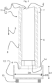
- Fig. 2 shows the same longitudinal section of punch sleeve 1 as Fig. 1 .
- the punch sleeve 1 is slid and mounted onto a ram 10.
- a punch apparatus 11 comprises the punch sleeve 1 and the ram 10.
- the ram 10 is a cylindrical body made from a steel and rotational symmetric with respect to the longitudinal axis 2 and axially secured by a nut 14, being a fastening element, in threading engagement with a threaded part of the ram 10 such that the nut 14 abuts the abutment shoulder 9a, as evident by comparing Figs. 1 and 2 .
- the nut 14 as radial clearance to the inner surface 9 such that the nut 14 can be screwed onto the ram 10.
- Fig. 2 depicts further a metal blank 12 already drawn by a cupping press into a cup shaped body having an inner diameter D4 larger than the diameter D1 and further having a wall thickness D5 and a height L4 measured analogously to the length L1.
- D4 is exemplarily 83 mm but can equally well be selected from a different diameter suitable for interacting with the punch sleeve 1.
- L4 is exemplarily 37 mm but can equally well be selected from a different height suitable for interacting with the punch sleeve 1.
- the metal blank 12 is drawn by a stroke of the punch sleeve 1 against the metal blank 12 and into a ring die 13; it is possible and conceivable to have more than one ring die, each placed below the die 13.
- the diameter D4 of the metal blank 12 is reduced to a smaller diameter equal to the diameter D1, and the height L4 is increased, e.g., by a factor of 1.5 or more.
- a method for drawing the metal blank 12 into a can body the following steps are carried out: a) the punch sleeve 1 or the punch apparatus 11 are provided, b) the metal blank 12 is provided, c) the metal blank 12 is drawn by moving the punch sleeve 1 and the metal blank 12 against each other, wherein the punch sleeve 1 is moved into the die 13.
- the punch sleeve 1 and thereby the punch apparatus 12 are light weighted and wear resistant having thereby in view drawing metal blanks into can bodies: a longer lifetime, lower energy consumption and lesser maintenance need. Said light-weightiness is predominantly due to that the sintered material comprises from 50 to 60 weight percent in total of titanium carbide and titanium carbonitride, being an example for in total of one or more selected from titanium carbide, titanium carbonitride and titanium nitride, in the presence of a wear resistance improving lower tungsten carbide content from 10 to 35 weight percent, and a toughness improving binder content of from 35 to 5 weight percent cobalt and nickel.
- the present invention is not limited to the design of the punch sleeve 1.
- the dimensions of the punch sleeve 1, especially the dimensions L1, L2, L3, D1, D2 and D3, can be changed relatively and/or in absolute values in view of a desired can body design and/or in view of a differently designed ram 10.
- a reference punch sleeve named hereafter punch sleeve A, was made from a sintered material consisting of the following components: 88 weight percent tungsten carbide and 12 weight percent cobalt.
- the sintered material of punch sleeve A had an approximate density of 14.3 g/cm 3 .
- punch sleeve B was made from a sintered material consisting of the following components: 38 weight percent in total of titanium carbide, 30 weight percent tungsten carbide, 24 weight percent cobalt, 6 weight percent nickel and 2 weight percent chromium.
- the sintered material of punch sleeve B had an approximate density of 8.0 g/cm 3 .
- a punch sleeve according to the invention named hereafter punch sleeve Inv., was made from a sintered material consisting of the following components: 53.5 percent tungsten carbide, 30 weight percent titanium carbide, 12 weight percent cobalt, 3 weight percent nickel and 1.5 weight percent chromium.
- the sintered material of punch sleeve B had an approximate density of 7.0 g/cm 3 .
- the wear tracks were deepest in the sintered material of punch sleeve A.
- the wear tracks were 13 % flatter (less deep) compared to the wear track depth in the sintered material of punch sleeve A.
- the were tracks were 21 % flatter (less deep) compared to the wear track depth in the sintered material of punch sleeve A and 9 % flatter (less deep) compared to the wear track depth in the sintered material of punch sleeve B.
- the inventive punch sleeve had not only a longer tool life due to an improved wear resistance in said method for drawing the metal blank 12, but also requires less energy to be moved due to its lower density.
- composition of the sintered materials of the further punch sleeves is based on the composition of the sintered material punch sleeve Inv. was made from, but each time with a systematic variation of one or more components.
- nickel content in the range from 1 to 4 weight percent in the further sintered materials improves the wear resistance over being outside of this range, for which the total content of nickel and cobalt was kept constant at 15 weight percent and the total content of titanium carbide and tungsten carbide was kept constant and 85 weight percent to yield 100 weight percent.
- the mean grain size of the tungsten carbide in the range from 1 ⁇ m to 3 ⁇ m improves the wear resistance over being outside of this range, for which the sintered material of punch sleeve Inv. was used. This trend was confirmed for any of the further sintered materials.
- titanium carbide and titanium carbonitride were selected from titanium carbide, titanium carbonitride and titanium nitride. Based on further prepared sintered materials having the same composition as the sintered material of punch sleeve Inv.
- titanium carbide with titanium carbonitride improves the wear resistance, especially, when the titanium carbide is essentially pure, i.e., TiC, and the titanium carbonitride has some tungsten, i.e., for example (Ti 0.85 ,W 0.15 )(C 0.8 ,N 0.2 ), (Ti 0.90 ,W 0.10 )(C 0.8 N 0.2 ), (Ti 0.95 ,W 0.05 )(C 0.8 ,N 0.2 ), (Ti 0.85 ,W 0.15 )(C 0.5 ,N 0.5 ), (Ti 0.90 ,W 0.10 )(C 0.5 ,N 0.5 ), (Ti 0.95 ,W 0.05 )(C 0.5 ,N 0.5 ), (Ti 0.95 ,W 0.05 )(C 0.5 ,N 0.5 ), (Ti 0. 0.95 ,W 0.05 )(C 0.5 ,N 0.5 ), (Ti 0. 0.0.05 )(C 0.5 ,
- titanium carbide was selected from titanium carbide, titanium carbonitride and titanium nitride.
- titanium carbonitride was selected from titanium carbide, titanium carbonitride and titanium nitride.
- titanium nitride was selected from titanium carbide, titanium carbonitride and titanium nitride.
- titanium carbide and titanium nitride were selected from titanium carbide, titanium carbonitride and titanium nitride.
- titanium carbonitride and titanium nitride were selected from titanium carbide, titanium carbonitride and titanium nitride.
- titanium carbide titanium carbonitride and titanium nitride were selected from titanium carbide, titanium carbonitride and titanium nitride.
Landscapes
- Chemical & Material Sciences (AREA)
- Engineering & Computer Science (AREA)
- Mechanical Engineering (AREA)
- Materials Engineering (AREA)
- Metallurgy (AREA)
- Organic Chemistry (AREA)
- Manufacturing & Machinery (AREA)
- Ceramic Products (AREA)
Priority Applications (2)
| Application Number | Priority Date | Filing Date | Title |
|---|---|---|---|
| EP23200731.0A EP4530001A1 (de) | 2023-09-29 | 2023-09-29 | Stanzhülse |
| PCT/EP2024/073923 WO2025067796A1 (en) | 2023-09-29 | 2024-08-27 | Punch sleeve |
Applications Claiming Priority (1)
| Application Number | Priority Date | Filing Date | Title |
|---|---|---|---|
| EP23200731.0A EP4530001A1 (de) | 2023-09-29 | 2023-09-29 | Stanzhülse |
Publications (1)
| Publication Number | Publication Date |
|---|---|
| EP4530001A1 true EP4530001A1 (de) | 2025-04-02 |
Family
ID=88238092
Family Applications (1)
| Application Number | Title | Priority Date | Filing Date |
|---|---|---|---|
| EP23200731.0A Withdrawn EP4530001A1 (de) | 2023-09-29 | 2023-09-29 | Stanzhülse |
Country Status (2)
| Country | Link |
|---|---|
| EP (1) | EP4530001A1 (de) |
| WO (1) | WO2025067796A1 (de) |
Citations (2)
| Publication number | Priority date | Publication date | Assignee | Title |
|---|---|---|---|---|
| US5736658A (en) * | 1994-09-30 | 1998-04-07 | Valenite Inc. | Low density, nonmagnetic and corrosion resistant cemented carbides |
| EP2746413A1 (de) | 2010-10-07 | 2014-06-25 | Sandvik Intellectual Property AB | Zementkarbidstempel |
-
2023
- 2023-09-29 EP EP23200731.0A patent/EP4530001A1/de not_active Withdrawn
-
2024
- 2024-08-27 WO PCT/EP2024/073923 patent/WO2025067796A1/en active Pending
Patent Citations (2)
| Publication number | Priority date | Publication date | Assignee | Title |
|---|---|---|---|---|
| US5736658A (en) * | 1994-09-30 | 1998-04-07 | Valenite Inc. | Low density, nonmagnetic and corrosion resistant cemented carbides |
| EP2746413A1 (de) | 2010-10-07 | 2014-06-25 | Sandvik Intellectual Property AB | Zementkarbidstempel |
Non-Patent Citations (1)
| Title |
|---|
| K. P. MINGARD ET AL.: "Comparison of EBSD and conventional methods of grain size measurement of hard metals", INT. JOURNAL OF REFRACTORY METALS & HARD MATERIALS, vol. 27, 2009, pages 213 - 223 |
Also Published As
| Publication number | Publication date |
|---|---|
| WO2025067796A1 (en) | 2025-04-03 |
Similar Documents
| Publication | Publication Date | Title |
|---|---|---|
| US8057571B2 (en) | Corrosion resistant tool | |
| US10363595B2 (en) | Cemented carbide necking tool | |
| EP2097189A1 (de) | Stempel für kaltbearbeitungsvorgänge | |
| KR102814569B1 (ko) | 분쇄·교반·혼합·혼련기 부재 | |
| JP2018039045A (ja) | 被覆冷間用金型 | |
| CN108884553B (zh) | 钛合金覆膜及钛合金靶材 | |
| JP6489412B2 (ja) | 硬質皮膜層、及び冷間塑性加工用金型 | |
| US20240009722A1 (en) | High-temperature forming tool | |
| EP4530001A1 (de) | Stanzhülse | |
| US12276011B2 (en) | Lightweight cemented carbide | |
| KR20170018831A (ko) | 초경합금 넥킹 공구 | |
| US7713327B2 (en) | Tool for coldforming operations with improved performance | |
| JP2005213599A (ja) | TiCN基サーメットおよびその製造方法 | |
| CN121941563A (zh) | 冲头套筒 | |
| EP0415633B1 (de) | Gesinterter Rohling aus Eisengrundwerkstoff zur spanlosen Verarbeitung und Verfahren zur Herstellung | |
| TWI800394B (zh) | 複合金沖棒 | |
| EP3821053B1 (de) | Ziehwerkzeug | |
| US11745261B2 (en) | Sintered gear | |
| JPS625981B2 (de) | ||
| MXPA06005933A (en) | Tool for coldforming operations with improved performance | |
| JPH0156136B2 (de) |
Legal Events
| Date | Code | Title | Description |
|---|---|---|---|
| PUAI | Public reference made under article 153(3) epc to a published international application that has entered the european phase |
Free format text: ORIGINAL CODE: 0009012 |
|
| STAA | Information on the status of an ep patent application or granted ep patent |
Free format text: STATUS: THE APPLICATION HAS BEEN PUBLISHED |
|
| AK | Designated contracting states |
Kind code of ref document: A1 Designated state(s): AL AT BE BG CH CY CZ DE DK EE ES FI FR GB GR HR HU IE IS IT LI LT LU LV MC ME MK MT NL NO PL PT RO RS SE SI SK SM TR |
|
| STAA | Information on the status of an ep patent application or granted ep patent |
Free format text: STATUS: THE APPLICATION IS DEEMED TO BE WITHDRAWN |
|
| 18D | Application deemed to be withdrawn |
Effective date: 20251003 |