EP4529979A1 - Verfahren und reaktor zur erzeugung von wärmeenergie und basischemikalien - Google Patents
Verfahren und reaktor zur erzeugung von wärmeenergie und basischemikalien Download PDFInfo
- Publication number
- EP4529979A1 EP4529979A1 EP23000133.1A EP23000133A EP4529979A1 EP 4529979 A1 EP4529979 A1 EP 4529979A1 EP 23000133 A EP23000133 A EP 23000133A EP 4529979 A1 EP4529979 A1 EP 4529979A1
- Authority
- EP
- European Patent Office
- Prior art keywords
- product gas
- reactor
- flame
- hydrogen
- reaction space
- Prior art date
- Legal status (The legal status is an assumption and is not a legal conclusion. Google has not performed a legal analysis and makes no representation as to the accuracy of the status listed.)
- Withdrawn
Links
Images

Classifications
-
- B—PERFORMING OPERATIONS; TRANSPORTING
- B01—PHYSICAL OR CHEMICAL PROCESSES OR APPARATUS IN GENERAL
- B01J—CHEMICAL OR PHYSICAL PROCESSES, e.g. CATALYSIS OR COLLOID CHEMISTRY; THEIR RELEVANT APPARATUS
- B01J8/00—Chemical or physical processes in general, conducted in the presence of fluids and solid particles; Apparatus for such processes
-
- B—PERFORMING OPERATIONS; TRANSPORTING
- B01—PHYSICAL OR CHEMICAL PROCESSES OR APPARATUS IN GENERAL
- B01J—CHEMICAL OR PHYSICAL PROCESSES, e.g. CATALYSIS OR COLLOID CHEMISTRY; THEIR RELEVANT APPARATUS
- B01J19/00—Chemical, physical or physico-chemical processes in general; Their relevant apparatus
- B01J19/0046—Sequential or parallel reactions, e.g. for the synthesis of polypeptides or polynucleotides; Apparatus and devices for combinatorial chemistry or for making molecular arrays
-
- B—PERFORMING OPERATIONS; TRANSPORTING
- B01—PHYSICAL OR CHEMICAL PROCESSES OR APPARATUS IN GENERAL
- B01J—CHEMICAL OR PHYSICAL PROCESSES, e.g. CATALYSIS OR COLLOID CHEMISTRY; THEIR RELEVANT APPARATUS
- B01J8/00—Chemical or physical processes in general, conducted in the presence of fluids and solid particles; Apparatus for such processes
- B01J8/008—Details of the reactor or of the particulate material; Processes to increase or to retard the rate of reaction
-
- B—PERFORMING OPERATIONS; TRANSPORTING
- B01—PHYSICAL OR CHEMICAL PROCESSES OR APPARATUS IN GENERAL
- B01J—CHEMICAL OR PHYSICAL PROCESSES, e.g. CATALYSIS OR COLLOID CHEMISTRY; THEIR RELEVANT APPARATUS
- B01J8/00—Chemical or physical processes in general, conducted in the presence of fluids and solid particles; Apparatus for such processes
- B01J8/08—Chemical or physical processes in general, conducted in the presence of fluids and solid particles; Apparatus for such processes with moving particles
- B01J8/087—Heating or cooling the reactor
-
- C—CHEMISTRY; METALLURGY
- C01—INORGANIC CHEMISTRY
- C01B—NON-METALLIC ELEMENTS; COMPOUNDS THEREOF; METALLOIDS OR COMPOUNDS THEREOF NOT COVERED BY SUBCLASS C01C
- C01B3/00—Hydrogen; Gaseous mixtures containing hydrogen; Separation of hydrogen from mixtures containing it; Purification of hydrogen; Reversible storage of hydrogen
- C01B3/02—Production of hydrogen; Production of gaseous mixtures containing hydrogen
- C01B3/04—Production of hydrogen; Production of gaseous mixtures containing hydrogen by decomposition of inorganic compounds
- C01B3/042—Decomposition of water
-
- B—PERFORMING OPERATIONS; TRANSPORTING
- B01—PHYSICAL OR CHEMICAL PROCESSES OR APPARATUS IN GENERAL
- B01J—CHEMICAL OR PHYSICAL PROCESSES, e.g. CATALYSIS OR COLLOID CHEMISTRY; THEIR RELEVANT APPARATUS
- B01J2208/00—Processes carried out in the presence of solid particles; Reactors therefor
- B01J2208/00796—Details of the reactor or of the particulate material
- B01J2208/00823—Mixing elements
- B01J2208/00831—Stationary elements
Definitions
- This invention relates to scalable metal-fuel concepts, to a reactor designed for oxidizing metal fuel and to optimized chemical conversions for generating energy and base chemicals at the same time for industrial use.
- This invention concerns the growing interest of transporting and storing energy, especially renewable helio-ecological energy and mashing the process streams with the global need of non-petrochemical or fossil chemical feedstock such as hydrogen, CO and all productes and goods derived thereof in all existing and future diverse regional industrial branches including the carbon use as its most reduced organic-chemical compounds.
- This invention addresses the need for raw-materials, chemicals and intermediates in a helio-energy driven circular economy with optimized energetic volume density transport and efficient release.
- Carbon capture and carbon sequestration as end-of pipe solutions are expensive philanthropic and will not provide preventive solution within the cyclic need of said value materials and feedstocks that will grow by growing "green” in sustainable perfectly circular economies.
- This invention demonstrates a new optimized solution to mesh all advantages and material streams mentioned above by providing a high volume-time yield conversion of stock metal yielding electricity on demand by using an easy and safe transport-infrastructure (global metal/metal-oxide cycle) and by producing hydrogen and standard carbon-intermediates continuously at the same time for base chemicals from abundant H 2 O and CO 2 fed back from and into the cycles.
- an easy and safe transport-infrastructure global metal/metal-oxide cycle
- WO 2014/173991 A1 proposed a full developed chemical-industrial hyperbranch of circles using aluminium as an energy storage material which is reacted with CO 2 to generate thermal energy for caloric grid-energy production and at the same time for converting CO 2 to CO which is used as a base chemical for synthesis of chemicals.
- Trowell Another group, Trowell, focuses on reacting aluminum in contact with water to release the reaction enthalpy in the form of heat and hydrogen. The result would be instant access to clean power, with no release of greenhouse gases.
- Trowell explains the underlying reactions and potential applications of this technology concept. While laboratory work has shown that the use of metal fuels with heat engines is technically feasible, no one has yet demonstrated the conversion in practice.
- One concept has been disclosed, for example, by BERGTHORSON, J.M. ET AL.: “Metal-Water Combustion for Clean Propulsion and Power Generation", APPLIED ENERGY, vol. 186, 1 January 2017 (2017-01-01), pages 13 - 27, XP055746514
- the next step toward turning the lab findings into usable technology will be to build a prototype conversion and couple it to a heat engine, again with a focus to optimize particle conversion at lower temperatues by proposing specialty metal powders including nano-spheres; compare https://www.mcgill.ca/newsroom/- channels/news/could-metal-particles-be-clean-fuel-future, published 2015.
- Alexandre Braconnier et al. published an attempt of CO 2 conversion towards a robust flame reporting low conversion, intermediates yield and droplet passivation even when using specially micronized Aluminium in a diluted transport gas set-up (see Alexandre Braconnier, Stany Gallier, Fabien Halter, Christian Chauveau; Aluminum combustion in CO2-CO-N2 mixtures; Proceedings of the Combustion Institute, Elsevier, 2021, 38 (3), pp.4355-4363 ).
- Oxygen burners using special micronized Aluminium yield a stable continuous flame ( F. Halter et al. in Applications in Energy and combustion Science, Vol. 13, https://doi.org/10.1016 (2023 )).
- Al, Mg and the Alkali metals and their alloys are reported to show self-sustained air-oxygen reactions from gas propelled powder transport. The reported temperatures indicate the importance of the self sustained kinetic within the flame geometry.
- WO 2021/228429 A1 disclosses the advantage of a liquid meatl fuel present in all Al smelting architectures to be dispersed into a reactor with precursor gases containing H 2 O or CO 2 and yields reasonable turnover together with the heat introcuced by the liquid aluminium into the system.
- Another parameter that reveals the difficulty of oxidation of Al with the oxidizers H 2 O and CO 2 compared to O 2 is the time to burn a particle, which is intrinsically much longer in case of H 2 O and CO 2 (compare M. Beckstead; Correlating aluminum burning times; Combust. Explo.
- the adiabatic flame temperature indicates the difficulty for accomplishing stable technical conversion. From D. S. Sundaram UDC 536.46 a, V. Yanga, and V. E. Zarkob; Combustion of Nano Aluminum Particles (Review). Combustion, Explosion, and Shock Waves, 2015, Vol. 51, No. 2, pp. 173-196., DOI: 10.1134/S0010508215020045 it is known that the adiabatic flame temperature is much lower and therefore much closer to the evaporation temperature of Al with CO 2 and H 2 O than it is for O 2 or air.
- the particle size has an influence on the implementation of full oxidation of aluminium mass.
- Dilip Srinivas Sundaram, Puneesh Puri, Vigor Yang A general theory of ignition and combustion of nano- and micron-sized aluminum particles. Combustion and Flame Volume 169, July 2016, Pages 94-109. https://doi.org/10.1016/j.combustflame.2016.04.005 report that oxidation time increases significantly with particle size. Moreover, it is general knowledge that higher volume specific surface of smaller particles supports mass transfer.
- CN109795984 A again repeats the technical prejudice by adding compartment device solutions to the different problems created by the low temperature and low enthalpy reaction compared to air and oxygen results in the literature and implements a step-by-step process. From this document no reaction conditions can be derived for a process or reactor that integrate all necessary materials to provide a self-sustained flame phase.
- the objective of the present invention is the provision of a process of converting selected metals in an atmosphere comprising H 2 O, H 2 O and CO 2 , H 2 O and NH 3 or H 2 O, CO 2 and NH 3 and optionally inert gases which allows a sustained flame.
- Another objective of the present invention is a reactor that is designed to carry out a process of effectively converting selected metals in an atmosphere comprising H 2 O, H 2 O and CO 2 , H 2 O and NH 3 or H 2 O, CO 2 and NH 3 and optionally inert gases by providing a sustained flame.
- a small ignition energy source a first flame, is used to ignite the larger amount of combustible metal allowing for melting or even evaporation of a said combustible metal in the presence of H 2 O or H 2 O containing oxydants and to generate a second flame.
- this second flame is maintained by adding a continuous stream of this larger amount of combustible metal and H 2 O or H 2 O containing oxydants to convert these to products in high yield and sustaining its own high enthalpic process as a second flame.
- the present invention relates to a process for producing thermal energy and base chemicals in a reactor having a reaction space with an inlet zone for reactants, a central zone and an outlet zone for a product gas, comprising at least the measures:
- the invention comprises a scalable process and a scalable reactor for the generation of power heat for local or grid use and essential base chemical gases hydrogen and carbon monoxide for decarbonized processes including raw materials and goods such as steal, syngas, synfuel, food chain ingredients as well as chemicals.
- hydrogen and carbon monoxide for decarbonized processes including raw materials and goods such as steal, syngas, synfuel, food chain ingredients as well as chemicals.
- the weaker reaction enthalpy and the slower germ-kinetics are effectively overcome in the confluence of a smaller flame zone allowing a sustained reaction of a much larger conversion zone of bulk metal fuel to be molten and/or evaporized into a visible radiating large sustained plasma zone yielding both, heat power and continuous non plugging oxide particles with a size and a density that those are driven out of the reaction radiation space (flame space).
- the standard reactor steal alloys in one embodyment were cooled by the heat transport and robust for both the expected water vapour corrosion and the hydrogen steal diffusion effects.
- the process of this invention is preferably a continuous process. But the process can also be operated in a batchwise manner.
- the reactor and the process of this invention are scalable within a broad range. Typical scales range from 10 kW to 10 GW, preferably from 50 kW to 1 GW of electrical energy produced from the heat generated by the process or the reactor, respectively.
- step a) of the process of this invention metallic main fuel selected from silicon, magnesium, iron, aluminum or alloy containing these metals is introduced into the inlet zone of the reaction chamber.
- Silicon which is a metalloid is designed in this application as a metal.
- step b) of the process of this invention H 2 O, or CO 2 or mixtures containing H 2 O, CO 2 and/or NH 3 are introduced into the inlet zone of the reaction chamber.
- This feed stream can optionally be diluted with inert gases, for example by nitrogen or argon.
- Steps a) and b) can be carried out separately.
- metallic main fuel and H 2 O or CO 2 containing streams can be introduced via separate feed lines into the reactor chamber.
- steps a) and b) can be carried out in a combined manner.
- metallic main fuel and H 2 O or CO 2 containing streams can be introduced as mixtures via one or more feed lines into the reactor chamber.
- Metallic main fuel can be used in the form of powder, granules, strips, wires, ingots or strands, preferably through continuous or discontinuous reactor feeds, optionally using airlocks.
- Metals used in the process of this invention are silicon, magnesium, iron or preferably aluminium.
- alloys containing two or more of these metals can be used.
- alloys are Aluminium-Magnesium alloys and Silicon-Aluminium alloys.
- Metallic fuel can by prepared from the corresponding oxdies by melt electrolysis, preferably by using electricity from regenerative sources, such as photovoltacis or wind energy.
- Metallic fuel can also be used as metal scrap, preferably as Aluminium scrap.
- the oxidation of the metallic main fuel in a flow-through reactor is particularly preferred to occur in a gas mixture with a predominant flow of H 2 O or CO 2 or NH 3 or H 2 O and CO 2 or H 2 O and NH 3 or H 2 O, CO 2 and NH 3 .
- the oxidation of the metallic main fuel preferably occurs in the substantial absence of oxygen gas. In essence, this means that the controlled addition of small amounts of oxygen gas, while not optimal, is still possible in principle without affecting the reaction as described, especially for the small flame or from the preferably initiating ignition device. However, better results are obtained in the absence of oxygen gas. Particularly preferably, therefore, the oxidation of metallic fuel is carried out in the absence of oxygen gas.
- inert gases can be present in the gas mixture in order to dilute the oxidant gas.
- the metals or metal alloys used as a metallic fuel in the process of this invention are available as a metallic raw material on an industrial scale and represent an alternative to other transportable energy sources.
- the metals or metal alloys are inert and non-hazardous to store and transport. This gives these metals or metal alloys a significant advantage as an energy source over crude oil, natural gas or coal, which are considered to be much more hazardous to the environment from their exploitation, their refinement, distribution and transport as well as their downstream use.
- the oxidant H 2 O is available from known sources. All kinds of water from all kinds of sources can be used. Fresh water can be used as well as salt water. Preferred is fresh water. H 2 O can be fed into the reactor as water vapour or as water mist. Preferred is water vapour.
- the oxidant CO 2 can be obtained from atmospheric gas, from combustion processes of all kinds or from other sources, and thus be removed from the atmosphere or industrial cycles.
- the process of this invention therefor has the advantage that no CO 2 is produced in the associated energy production, but is actually consumed.
- the resulting metal oxide is collected and highly inert and does not lead to any environmental pollution.
- the resulting reaction product(s) hydrogen or cabon monoxide or hydrogen and carbon monoxide are hazardous gases.
- extraction, handling and storage of hazardous gases have been possible for a long time and, in particular, according to the process technologies used in the chemical industry today, without any problems and in compliance with appropriate safety standards.
- the risk potential of carbon monoxide and hydrogen is thus on a par with that of other hazardous chemical substances.
- the reaction product(s) hydrogen and/or carbon monoxide can be used advantageously in many industrial processes.
- Hydrogen can be used in many reduction processes, for example to produce metals, such as iron, from metal oxides, or to carry out hydrogenations of organic compounds.
- Hydrogen can also be used as a fuel or as a source of thermal energy.
- Mixtures of carbon monoxide and hydrogen can be used in many industrial processes to produce energy-rich hydrocarbon compounds, such as for the production of fuels, such as kerosene.
- Increased use of the process of the invention would provide carbon monoxide and/or hydrogen fuel for industrial purposes.
- the combustion of hydrocarbons from the reaction products of carbon monoxide and hydrogen would in turn provide carbon dioxide, which can again be fed to the process according to the invention or when comming from this process is at least CO 2 -footprint neutral.
- the essential advantage of the process according to the invention thus consists in a universally, decentrally and rapidly applicable energy generation, without additional CO 2 pollution of the environment caused thereby, whereby the reaction product(s) hydrogen or hydrogen and carbon monoxide can be fed to a material cycle.
- Nitrogen as inert transport gas for dilution and flame process control will not lead to the undesired NOx-problem of oxygen-rich burners. This is an important quality and advantage of the high temperature low oxygen process of this invention as the metal proved to capture oxygen at these reaction kinetics and temperature to the advantage of this gas purification.
- Reactant NH 3 is also available from known sources. NH 3 can be used as a source of hydrogen. The oxidation reaction(s) in the reactor generate huge amounts of thermal energy and therefore high temperatures are present in the reactor chamber. This avoids formation of nitrogen oxides as by-products from the nitrogen generated by NH 3 decomposition.
- step c) of the process of this invention particles of metallic secondary fuel and oxidant or hydrogen and oxidant or mixtures of two or more of said particles, hydrogen and oxidant are introduced into the inlet zone of the reactor.
- Particles of metallic secondary fuel and oxidant or hydrogen and oxidant can be introduced via separate feed lines into the reactor inlet zone.
- mixtures of particles of metallic secondary fuel and oxidant or of hydrogen and oxidant are introduced via common feed line(s) into the reactor inlet zone.
- the feed line(s) for secondary fuel and oxidant terminate within the reactor inlet zone and the feed stream(s) of secondary fuel and oxidant are oriented in a manner that separate feed streams of secondary fuel and oxidant mix at the end of said line(s) within the reactor inlet zone.
- This mixture of secondary fuel and oxidant is ignited by means of an ingnition device to generate a first flame at the location of the secondary fuel-oxidant mixture.
- the secondary fuel-oxidant mixture is generated outside the reactor and is provided via feed line(s) into the reactor inlet zone.
- the mixture of secondary fuel and oxidant is ignited in step d) by means of an ingnition device to generate a first flame at the location of the secondary fuel-oxidant mixture.
- metals for the secondary fuel the same metals can be used as for the main fuel.
- silicon, magnesium, iron and preferably aluminium particles or particles of alloys of two or more of these metals can be used.
- metallic particles used in step c) have diameters below 100 ⁇ m, preferably below 10 ⁇ m.
- a preferred diameter range for metallic particle is between 100 nm and 10 ⁇ m.
- oxygen air or oxygen-containing chemicals can be used in step c).
- Preferred oxidants are oxygen, air, H 2 O and/or CO 2 .
- Ignition devices can be used for igniting the mixture of secondary fuel and oxidant to generate the first flame. Ignition devices are known to the skilled artisan.
- Examples of ignition devices are electric arcs arranged in the inlet zone at the end of the feed line(s), inductive heaters or lasers arranged outside the reactor, the radiation of the laser being coupled into the reaction chamber through one or more windows in the reactor jacket or the inductive heater generating heat acting on the space region at the end of the feed line(s) to generate the first flame.
- the first flame generated in step d) is used to generate in step e) a second flame which forms a reaction zone by reaction of metallic main fuel with H 2 O or CO 2 or with H 2 O, CO 2 and/or NH 3 .
- the first flame triggers the main reaction by igniting the metallic main fuel to react in an oxidation reaction.
- a second typically larger flame is formed.
- the first flame In order to trigger the main reaction the first flame must be directed towards the metallic main fuel that is present in the reactor inlet zone. Moreover, the first flame generates a temperature within the metallic main fuel that at least a portion of said metallic main fuel melts. This causes said metallic main fuel to react with the H 2 O the CO 2 or with the H 2 O, CO 2 and/or NH 3 and to generate a second flame, preferably from at least partially vapourized metal fuel.
- the oxidation reaction of the metallic main fuel results in a product gas-particle mixture containing hydrogen and oxidized metal or carbon monoxide and oxidized metal or hydrogen, carbon monoxide and/or nitrogen and oxidized metal, depending on the oxidant used in the main reaction.
- the temperature of the second flame can be controlled via the process conditions.
- the throughput of the metallic main fuel and H 2 O or CO 2 or H 2 O containing oxidant through the reactor the optional presence of inert gases or the continued presence of the first flame may influence the amount of heat generated during the oxidation reaction.
- step c) is used to provide ignition of the metallic main fuel only and may be terminated after the second flame has been established.
- step c) can be continued after said ignition during the main reaction between metallic main fuel and the H 2 O and/or CO 2 containing oxidant in order to support the stability of the second flame even under turbulent conditions.
- a temperature in the first flame in the range between 2500 and 3500°C, preferably between 2500 and 3000°C is generated. This will guarantee an ignition of the metallic main fuel and formation as well as propagation of the the second flame.
- the second flame generates temperatures within the metallic main fuel that at least a portion of said metallic main fuel evaporates.
- the process conditions are chosen in a manner, so that the second flame continues to cause a portion of the metallic main fuel to evaporate. This can be achieved, for example, by controlling the throughput of metallic main fuel and oxidant or by using a selected molar ratio of metallic main fuel and oxidant in the reaction zone.
- temperatures of 2000°C or higher are generated, more preferred temperatures between 2000 and 3500°C, and very preferred temperatures between 2500 and 3000°C.
- the temperatures in the reaction zone are measured by using a radiation thermometer.
- low fractions of oxygen may be present in the fuel stream for the second flame.
- the amount of oxygen in a feed gas stream is 5 Vol.-% or lower. But preferably no oxygen is present in a feed gas stream.
- the feed gas stream for the second flame is optimized to turnover into hydrogen or into CO or into hydrogen and CO. Although oxygen would always contribute to increase the heat enthalpy of the process, however this results in a lower yield of the desired base chemical products per metal fuel.
- a reaction zone is generated by the action of the first flame by melting a portion of the metallic main fuel thereby causing said metallic main fuel to react with H 2 O or with CO 2 or with H 2 O, CO 2 and/or NH 3 to generate a second flame resulting in a product gas containing hydrogen and oxidized metal or carbon monoxide and oxidized metal or hydrogen, carbon monoxide and/or nitrogen and oxidized metal.
- inert gas(es) are present in the product gas if such inert gas(es) are introducted into the inlet zone of the reactor.
- the product gas consists of hydrogen and oxidized metal or of carbon monoxide and oxidized metal or of hydrogen, CO and oxidized metal, or of hydrogen, N 2 and oxidized metal, or of hydrogen, CO, N 2 and oxidized metal.
- the product gas can also contain minor proportions, e.g. up to 10 vol.-%, of H 2 O, CO 2 , NH 3 and/or unreacted metallic fuel.
- product gas ingredients hydrogen, N 2 , CO, H 2 O, CO 2 , NH 3 and inert gas(es) are present as gases product gas ingredients oxidized metal and metallic fuel are present as particulate solids.
- step f) the product gas is discharged from the reaction space exit zone via a discharge line and is introduced into a separation device for solids.
- One or more discharge lines may be present which discharge into one or more separation devices.
- Preferably one discharge line is present which discharges into one separation device.
- separation devices are centrifugal separators, known as cyclones, or fabric filters or electric filters or ceramic filters.
- Preferred separation devices are cyclones.
- Cyclones serve as mass force separators in technical plants for the separation of solid or liquid particles contained in gases. Cyclones are used, for example, for flue gas cleaning. Centrifugal forces, which are created by generating a vortex flow, are used for separation.
- the product gas as the carrier of the particles to become separated, is set into a rotating motion by its own flow velocity through the suitably designed fixed separator.
- the solid particles are separated in the cyclone by the particle mass. Common outer diameters of cyclones range from 20 cm to 6 m.
- the particle-loaden product gas can be fed tangentially or axially to the rotationally symmetrical separator chamber. In both designs, the particles are transported to the wall of the separator chamber.
- a tangential cyclone separator consists essentially of four parts: The inlet cylinder (top), the cone (center), the particle collection vessel or hopper (bottom), and the dip tube (centered down from the top of the inlet cylinder).
- the product gas/particle mixture is injected tangentially and brought into a circular path. Due to the taper of the subsequent cone, the rotational speed increases to such an extent that the particles are thrown against the cone walls by the centrifugal force and slowed down to such an extent that they break away from the flow and trickle down into the collecting vessel.
- the purified product gas exits the cone upward through the central dip tube.
- the guidance of the mixture can be reinforced by baffles attached to the inner wall of the separator in the shape of a spiral.
- the transition from the cone to the hopper is often additionally closed by an apex cone standing in the center, leaving only an annular slot between the cone wall and the apex cone through which the particles enter the hopper.
- the hopper can be emptied during operation, with discharge taking place via a rotary valve to prevent gas exchange with the environment.
- the swirl is mostly generated by guide vanes.
- the immersion tube is located opposite the gas inlet.
- the separated particles pass through an annular gap between the separator wall and the immersion tube into a collecting vessel.
- the direction of flow is not reversed in the case of the axial separator.
- Axial separators are generally used for the operation of multicyclones. These can consist of up to several hundred individual separators.
- a fabric filter solid particles are separated from the product gas.
- the particles mainly accumulate on the outside of the filter material and form a so-called filter cake, which then itself acts as a highly efficient separator. Due to the filter cake, the differential pressure in the filter system and thus the energy consumption increases continuously, making regular regeneration necessary. This usually takes place by means of a gas pulse introduced against the direction of flow, which ensures that the filter cake is thrown off.
- the ejected filter cake is usually removed from the collection hopper of the filter system by means of a rotary valve.
- a fabric filter is a bag filter.
- This is a surface filter in which the filter medium is formed into a tube.
- bag filters have become established in gas cleaning and dust removal in numerous industrial processes. Bag filters consist of fiber material woven into tubes. In hot gas filtration, metallic wire mesh is frequently used.
- the product gas containing solid particles is ideally fed to the filter bags in a crossflow to avoid upflow against the sedimentation direction of the particles.
- the product gas is directed over a distribution plate where preseparation takes place and the product gas flow in the filter housing is equalized. The actual separation of the particles takes place on the surface of the filter medium or of the filter cake depositing on it.
- the product gas leaving the reactor is dedusted.
- electrical particle separation solid particles are negatively charged in the gas stream with the aid of spray electrodes and deposited on opposite precipitation anodes.
- a DC voltage of 30 to 80 kV, for example, is applied between the spray and precipitation electrodes.
- the specific resistance of the charged particles is decisive for deposition. If this is too high, deposition no longer takes place.
- the separated solids are conveyed to a solids silo. The solids are discharged either dry or with the aid of a mixing screw, after the solids have previously been moistened with water.
- step g) the solids contained in the the product gas are removed in the separation device, thereby producing a purified product gas having no or a reduced solids content.
- a purified product gas having no or a reduced solids content.
- at least 90 weight-%, more preferred more than 99 weight-% of the solids present in the product gas entering the separation device are removed by this device.
- step h) the purified product gas is discharged from the separation device.
- step i) thermal energy generated when oxidizing the metal main fuel is extracted and transferred into a heat transfer medium. This thermal energy is used for generation of electrical energy and/or for heating.
- step i) the thermal energy generated in the reaction space, contained in the product gas and/or in the purified product gas is transferred into a heat transfer medium. This is achieved by means of one or more heat exchangers connected with the reactor jacket and/or one or more heat exchangers connected with the discharge line between the reaction space exit zone and the separation device and/or one or more heat exchangers connected with a line removing the purified product gas from the separation device.
- Heat transfer media used in the heat exchanger(s) are known to the skilled artisan.
- Examples of heat transfer media are water, glycols, glycerine, molten metals, molten salts or thermal oils, such as silicones or high-boiling hydrocarbons.
- Preferred heat transfer media are water, thermal oils or molten salts.
- the thermal energy contained in the heat transfer media can be supplied to an exploiting consumer.
- Exploiting consumers can be almost all technical and chemical energy converters.
- low-pressure or high-pressure steam turbines for power generation Stirling engines and other heat engines or direct power generators on temperature gradients
- thermolysis reactors in particular reactors for water thermolysis to hydrogen can be mentioned as exploiting consumers.
- the hydrogen or hydrogen/carbon monoxide generated in the process of this invention is stored or fed to a chemical conversion.
- the generated energy can be dissipated for energy conversion or heat or cold generation, e.g. for heating, by storing it or consuming it directly or indirectly.
- the thermal energy generated can, for example, be fed to a low-pressure or, preferably, a high-pressure steam turbine in order to generate electricity.
- a portion of the heat generated in the process is backfeeded to the reactants introduced into the reactor.
- the rate of reaction is not only controlled through the intake of the metal particles and their flow mode, such as swirl rotation, concentric laminar, angular perpendicular or even confluent controversial injection, but also through the point of contact were the mass inflow of metallic main fuel contacts the temperature zones of the first flame(s).
- Particulate metals such as Mg, Si, Fe, Ti, Ca, Va, Ge, Ni, Mn, Zn and Sn may be used for generating the first flame to provide the overall two stage vapourizing action by the interplay between first and second flame.
- Si, Mg, Fe or Al are used for generating the first flame, most preferred is Al.
- the same metals are used for generating the first and the second flame.
- Most preferred Al is used for generating the first and the second flame.
- the process and the reactor of this invention establish a controlled first oxidizing reaction stage with net negative enthalpy by generating a first flame. And in the same reactor a second reaction stage with higher turnover and negatve enthalpie is established giving a joined enthalpy to the heat of reaction.
- a preferred process or reactor uses a first inlet and a second inlet for injecting a particle stream of metall fuel, e.g. by using a transport gas or a ballistic mass acceleration similar to a pump swirl or propeller.
- the first metal fuel powder for generating the first flame may have a particle size in the range between 1 and 500 ⁇ m, but also particle sizes of smaller than 1 ⁇ m are possible.
- the second metal fuel powder for generating the second flame may have a much higher particle size, e.g. a particle size in the range of 100 ⁇ m to 1 mm or larger.
- the heat of the first flame and a portion of the heat of the back-feeded partially reacted particle mixtures will allow a substantial micronization and vapourisation in-process of the second metal fuel feed to improve conversion to a satisfactory steady state flame process, which would not be obtained without the in-process micronisation by the heat of the first flame.
- Statistical thermodynamic consideration shows that such first flame core would need to be close to 2500, 2700 or above 3000°C in order to generate a self sustained second flame zone with the same oders of temperature.
- those high temperatures generated in the process and reactor of this invention can be well managed, controlled and brought to the respective energy transforming heat exchangers of standard equipment.
- the dome of the exchangers would be needed to be sized according to black-body radiation and are not a concern for large scale equipment. This means that high temperatures support heat transfer by radiation.
- the heat exchangers are no longer dependent on high chaotic gas flow transport, but radiation is the guiding design principle for the effective fuel reactor flame cell with obvious scaling (size) and numbering (parallel reactor) advantages.
- the metal oxides, such as alumina, resulting form the process of this invention is of best quality and contains metal traces which would allow for further circulating loops as well as for direct use of this high quality product into smelter circular use much better than any mineral feedstock technically available for smelter metal production.
- This quality solid phase after separation from the gases via standard means like cyclones or solid product ash traps is as a typical product of the inventive process. A product with such quality can otherwise only be obtained via multi step labourious and costly additional rectification.
- Transported via carrier gas typically a mixture of an inert carrier and oxidant, such as water vapour / CO 2 , is introduced into the reaction space so that the second flame is stable over a continuous period of time.
- carrier gas typically a mixture of an inert carrier and oxidant, such as water vapour / CO 2
- the reaction proceeds in a heat and gas controlling apparatus so that hot gases can be returned to the input zone of the reactor and the reaction products including the thermal energy generated during the reaction can be exploited and separated in a controlled manner.
- the metal main fuel for the second flame can be of less granulation, higher size or different qualities, such as in liquid form (liqiud metal injection) or even solid forms, such as bars, wires or pellets.
- the first flame is stabilized and controlled and shapedvia flow rotation e.g. by a swirl, for example by using a mixing device.
- the reactor of this invention contains a reaction space A) formed by a reactor jacket.
- Reaction space contains an inlet zone for reactants, a central zone and an outlet zone for a product gas.
- the reactor has at least one feed line for metallic main fuel and/or for mixtures containing H 2 O, CO 2 and/or NH 3 and optionally inert gas(es) said feed line(s) open into the inlet zone.
- the reactor has at least one discharge line for the product gas generated in the reaction space said discharge line being located in the outlet zone.
- a central zone is present in which the reaction between metallic fuel and oxidant continues. Thus, this reaction occurs in the inlet zone and in the central zone or in a portion of the central zone.
- the reactor housing is made from heat resistant material, such as high melting metals, e.g. steel, molybdenum or tungsten, or ceramics or refractory bricks.
- the shape of the reactor can vary to a large extent.
- Reactors can have various forms, for example reactors can be in the shape of a tube or a bundle of tubes.
- reactors define a reaction space of different shape, e.g. in the form of a cuboid.
- the reactor walls are lined with refractory bricks.
- the reactor contains two or more feed lines for fuel discharge into the inlet zone.
- these feed lines may proceed axially or parallel to the cylinder axis and/or proceeding radially perpendicular through the reactor jacket into the inlet zone or proceeding tangentially trough the reactor jacket. Combinations of these line routings are possible.
- the inlet zone may be a portion of the reaction space beginning immediately after a circular end face of a cylindrical reactor.
- the inlet zone may have a conical shape and is attached to one of the circular end faces of the cylindrical reactor jacket.
- fuel metal fuel and oxidant are introduced into the inlet zone.
- Fuel for the first flame is introduced via one or more feed lines D) into the inlet zone.
- Fuel for the second flame is introduced via one or more feed lines into the inlet zone.
- Metal fuel may be introduced via one line and oxidant may be introduced via another line or a mixture of metal fuel and oxidant may be introduced in one or more feed line(s).
- Feed line(s) D) terminate in the inlet zone and introduce the fuel for the first flame into this zone.
- an ignition device E) acts upon the fuel and ignites the first flame.
- One or more first flames can be generated in the inlet zone.
- the first flame is used to start the main reaction to result in a second flame.
- the first flame can be used to support the main reaction. In this embodiment the first flame will continue to exist or will exist intermittently after ignition of the second flame.
- Different ignition devices E may be used. Examples thereof are given above.
- the reactor jacket may contain a window for monitoring the reaction processes in the reaction space and/or to provide laser radiation into the reactor space to ignite the first flame.
- the reactor jacket is preferably equipped with a heat exchanger C) for recovering thermal energy produced by the reaction process in the reaction space.
- the reactor contains one or more discharge lines for discharging product gas from the exit zone into the separation device(s).
- the exit zone is a portion of the reaction space beginning immediately before the outlet for the product gas of the reactor. In a cylindrical reactor the exit zone begins upstream the circular end face.
- the discharge line may be one or more tubes or a conical hollow body with is attached to the circular end face of the cylindrical reactor and is connected with a separation device.
- the discharge line is preferably equipped with a heat exchanger C) for recovering thermal energy from the product gas leaving the reactor.
- Separation device B is used to remove solid particles from the product gas.
- Different separation devices B) may be used. Examples thereof are given above.
- the purified product gas leaving the separation device via a discharge line may be fed to one or more heat exchanger(s) in order to transfer the thermal energy contained in said purified product gas to a heat transfer medium. Thereafter, the cooled product gas is fed into storage container(s) or is transferred to a plant for further processing. In an alternative embodiment the hot purified product gas is fed directly via a discharge line to a plant for further processing.
- Heat recovery can be achieved using classical heat exchangers known to the skilled artisan.
- the metallic fuel provided in step a) is introduced into the inlet zone of the reaction space in the form of a powder, chips, pellets, ingots or metal rods.
- the metallic fuel provided in step a) is an aluminium-magnesium alloy or preferably aluminium and the oxidized metal generated in step e) is aluminia.
- the H 2 O introduced into the inlet zone of the reaction space in step b) is in the form of a water mist or, in particular, as water vapor.
- water vapor or a mixture of water vapor and carbon dioxide or a mixture of water vapor and ammonia is introduced in step b), the water vapor or the mixtures optionally being diluted with inert gas, in particular with nitrogen.
- Another preferred process of this invention relates to introduction of the metallic fuel and the H 2 O or CO 2 or the mixture containing H 2 O, CO 2 and/or NH 3 into the inlet zone of a cylindrical reaction space via one or more axially and/or radially and/or tangentially extending pipes.
- inert gas and/or water vapor or mixture containing water vapor, carbon dioxide and/or ammonia are introduced into the inlet zone of the reaction space via a plurality of pipes tangentially extending through the reactor jacket, as a result of which a vortex is formed in the reaction space which moves in the direction towards the outlet zone.
- the mixture introducted in step c) is a hydrogen-oxygen mixture, a hydrogen-air mixture, a hydrogen-chlorine mixture, an acetylene-air mixture or a mixture of metal particles with diameters of less than 100 ⁇ m and water vapor.
- the first flame is ignited by using an ignition device, preferably by using an electric arc arranged in the inlet zone, an inductive heater or a laser arranged outside the reactor, the radiation of which is coupled into the reaction chamber through one or more windows in the reactor jacketl, so that the electric arc, inductive heater and/or laser radiation act on the mixture introduced in step c).
- an ignition device preferably by using an electric arc arranged in the inlet zone, an inductive heater or a laser arranged outside the reactor, the radiation of which is coupled into the reaction chamber through one or more windows in the reactor jacketl, so that the electric arc, inductive heater and/or laser radiation act on the mixture introduced in step c).
- the second flame in step e) generates temperatures above 2000°C by the reaction of the metallic fuel with the H 2 O or CO 2 or with the H 2 O, CO 2 and/or NH 3 .
- the temperatures generated in the second flame in step e) cause evaporation of a portion of the metallic fuel.
- the product gas is introduced in step f) into one or more cyclones.
- the thermal energy generated in the reaction space is transferred to a heat transfer medium running through a heat exchanger which is connected with the reactor jacket and/or that the thermal energy of the product gas is transferred to a heat transfer medium running through a heat exchanger connected with the discharge line between the reaction space exit zone and the separation device and/or that the thermal energy of the purified product gas is transferred to a heat transfer medium running through a heat exchanger connected with a line removing the purified product gas from the separation device.
- the outer jacket of the reactor is cooled by means of a heat transfer medium, preferably by using water.
- the heat transfer medium running through the heat exchanger(s) is water, a thermal oil or a molten salt.
- the hot purified product gas is introduced into a heat exchanger located downstream the separation device for cooling said purified product gas and the thermal energy contained in said purified product gas is fed to a heat transfer medium.
- the hot purified product gas is fed from the separation device into a chemical reactor in order to carry out reduction reactions with the hydrogen contained in the purified product gas or to react the mixture of hydrogen and carbon monoxide contained in the purified product gas.
- the hydrogen, the carbon monoxide or the hydrogen/carbon monoxide generated in the process of this invention my become chemically reacted on site.
- a variety of chemical reactions are available in which these basic material(s) can be refined.
- hydrogen can be used for hydrogenation of organic compounds or in reduction reactions, for example in ammonia synthesis or in the manufacture of iron from iron oxide.
- Carbon monoxide can be reacted with water to form methanol, for example.
- carbon monoxide and hydrogen can be further processed in a Fischer-Tropsch reaction to various organic compounds.
- the metal used as metallic fuel has been produced from metal oxides without generating CO 2 , preferably in a fused-salt electrolysis plant, which has no carbon electrodes.
- a preferred reactor of this invention is characterized by a reaction space which is a volume enclosed by refractory bricks or which is the interior of a cylindrical jacket made of metal or ceramics.
- the reactor contains a cylindrical reaction space, into the inlet zone of which one to five axially extending feed lines open, preferably two or three axially extending feedlines and/or into the inlet zone of which one or more feed lines extending radially through the outer reactor jacket open into its inlet zone, provided that at least one feed line is available for introducing a mixture of particles of metallic fuel and oxidant or a mixture of hydrogen and oxidant.
- the reactor contains a cylindrical reactor jacket through which a plurality of feed lines pass tangentially to feed the inlet zone with reactants.
- the ignition device is selected from one or more electric arcs arranged in the inlet zone at the end of the feed line D) and/or one or more inductive heaters or lasers are arranged outside the reactor, the radiation of the laser is coupled into the reaction space through one or more windows in the reactor jacket, so that electric arcs and/or electromagnetic radiation and/or laser radiation act on the space region at the end of the feed line D) to generate the first flame.
- a cylindrical reaction jacket is provided through which a plurality of feed lines pass tangentially to feed the inlet zone with inert gas and/or water vapor, CO 2 or a mixture containing water vapor, carbon dioxide and/or ammonia, as a result of which a vortex is formed on the interior of the reaction jacket, which vortex moves in the direction of the outlet zone.
- the separation device is one or more cyclones, preferably two or three cyclones.
- this contains a heat exchanger which is connected with the reactor jacket and/or this contains a heat exchanger connected with the discharge line between the reaction space exit zone and the separation device and/or this contains a heat exchanger connected with a discharge line removing the purified product gas from the separation device, or this contains a discharge line for the hot purified product gas from the separation device which is connected with a chemical reactor to carry out reduction reactions with the hydrogen contained in the purified product gas or to react the mixture of hydrogen and carbon monoxide contained in the purified product gas.
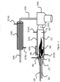
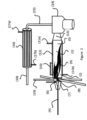
- reactors illustrated in Figures 1 to 3 are modified embodiments of a reactor disclosed in an article of F. Halter et al. in Applicatinos in Energy and combustion Science, Vol. 13, https://doi.org/10.1016 (2023 ).
- the reactor of Figure 1 contains a reaction space (1) with an inlet zone (2) for reactants and an exit zone (3) for product gas.
- Inlet zone (2) contains axial feed tubes for a mixture of metal fuel and oxidant (4, 5) for the first flame (8) and the second flame (9).
- an ignition device (6) is positioned. Ignition device (6) forms an electric arc and ignites the fuel transported through feed line (4) resulting in the first flame (8). This first flame (8) in turn ignites the fuel transported through feed line (5) resulting in the second flame (9).
- the reactor is formed by a cylindrical reactor jacket containing a window (10) for inspecting the reaction taking place in the interior of the reactor.
- Reactor jacket is surrounded by a heat exchanger (12) having an inlet line (11a) and an exit line (11b) for heat transfer medium, e.g. water.
- a heat exchanger (12) having an inlet line (11a) and an exit line (11b) for heat transfer medium, e.g. water.
- One front end of the cylindrical reactor jacket is sealed by a conically shaped end piece (7).
- Axial feed lines (4, 5) pass through end piece (7).
- the other circular end face of the cylindrical reactor jacket is connected with a conical discharge line (13) for the product gas which connects exit zone (3) with a cyclone (14) for separating solid particles from the product gas.
- the purified product gas is fed from cyclone (14) va line (15) to heat exchanger (16) for extraction of thermal energy from the purified product gas to a heat transfer medium, e.g. water.
- Heat exchanger (16) has an inlet line (17a) and an exit line (17b) for the heat transfer medium as well
- the reactor of Figure 2 contains a reaction space (1) with an inlet zone (2) for reactants and an exit zone (3) for product gas.
- Inlet zone (2) contains an axial feed tube for a mixture of metal fuel and oxidant (4) for the first flame (8) and several radially or tangentially arranged feed lines (19) for the metal main fuel or oxidant(s) or for a mixture of metal main fuel and oxidant(s) for the second flame (9).
- the second flame forms (9) a swirl around the first flame (8) and propagates as a swirl in the direction of the exit zone (3).
- an ignition device (6) is positioned.
- Ignition device (6) forms an electric arc and ignites the fuel transported through feed line (4) resulting in the first flame (8).
- This first flame (8) in turn ignites the fuel transported through feed lines (19) resulting in the second flame (9).
- the reactor is formed by a cylindrical reactor jacket containing a window (10) for inspecting the reaction taking place in the interior of the reactor.
- Reactor jacket is surrounded by a heat exchanger (12) having an inlet line (11a) and an exit line (11b) for heat transfer medium, e.g. water.
- One front end of the cylindrical reactor jacket is sealed by a conically shaped end piece (7).
- Axial feed line (4) passes through end piece (7).
- the other circular end face of the cylindrical reactor jacket is connected with a conical discharge line (13) for the product gas which connects exit zone (3) with a cyclone (14) for separating solid particles from the product gas.
- the purified product gas is fed from cyclone (14) va line (15) to heat exchanger (16) for extraction of thermal energy from the purified product gas to a heat transfer medium, e.g. water.
- Heat exchanger (16) has an inlet line (17a) and an exit line (17b) for the heat transfer medium as well as a discharge line (18) for the cooled product gas.
- the reactor of Figure 3 contains a reaction space (1) with an inlet zone (2) for reactants and an exit zone (3) for product gas.
- Inlet zone (2) contains an axial feed tube for a mixture of metal main fuel and oxidant(s) (4) for the second flame (9) and several radially or tangentially arranged feed lines (19) for the metal fuel or oxidant(s) or for a mixture of metal fuel and oxidant(s) for the first flame (8).
- the first flame forms (8) a swirl around the first flame (9) and propagates as a swirl in the direction of the exit zone (3).
- an ignition device (6) is positioned. Ignition device (6) forms an electric arc and ignites the fuel transported through feed line(s) (19) resulting in the first flame (8). This first flame (8) in turn ignites the fuel transported through feed line (4) resulting in the second flame (9).
- the reactor is formed by a cylindrical reactor jacket containing a window (10) for inspecting the reaction taking place in the interior of the reactor. Reactor jacket is surrounded by a heat exchanger (12) having an inlet line (11a) and an exit line (11b) for heat transfer medium, e.g. water. One front end of the cylindrical reactor jacket is sealed by a conically shaped end piece (7).
- Axial feed line (4) passes through end piece (7).
- the other circular end face of the cylindrical reactor jacket is connected with a conical discharge line (13) for the product gas which connects exit zone (3) with a cyclone (14) for separating solid particles from the product gas.
- the purified product gas is fed from cyclone (14) va line (15) to heat exchanger (16) for extraction of thermal energy from the purified product gas to a heat transfer medium, e.g. water.
- Heat exchanger (16) has an inlet line (17a) and an exit line (17b) for the heat transfer medium as well as a discharge line (18) for the cooled product gas.
- the reactor designed for both generation of heat and valuable chemical products is composed of the following main parts:
- the reaction chamber is surrounded by a cooled double-walled pipe, 0.6 m long with an internal diameter of 0.105 m.
- the gaseous reaction products and oxide particles are driven through a convergent line to the tangential entry of a first cyclone.
- a second cyclone improves solid oxide trapping. Then the hot gas flows to a secondary heat exchanger.
- the metal fuel is aluminium powder with a purity greater than 99.8% and supplied by Carl Roth.
- Solid fuel injection was performed by using a PALAS BEG 1000 type B which allows a continuous and homogeneous injection of particles.
- the gas temperature profile in the reaction chamber is characterized using a set of type K thermocouples located along the chamber axis.
- the second flame was ignited in the following conditions: Initial reaction between pulverized Al (5-20 ⁇ m) and additional steam in the order of equi-stochiometric conditions reaching more than 2000°C. Pulverized aluminum size was progressively increased up to 200 ⁇ m to prove the versatility of the invention.
- Delivered power between 2 and 25kW was achieved with a combined mass flowrate of 0.1 to 1 g/s of pulverized Aluminum.
- Aluminum oxide collected showed satisfactory measurable conversion and yield at this stage of experimental setup. Unreacted aluminum traces could be easily explained by the initial ignition process.
- the second flame was ignited in the following conditions: Initial reaction between pulverized Al (5-20 ⁇ m) and additional CO 2 in the order of equi-stochiometric conditions reaching more than 2000°C. Pulverized aluminum size was progressively increased up to 200 ⁇ m to prove the versatility of the invention.
- Delivered power between 2 and 25kW was achieved with a combined mass flowrate of 0.1 to 1 g/s of pulverized Aluminum.
- Aluminum oxide collected showed satisfactory measurable conversion and yield at this stage of experimental setup. Unreacted aluminum traces could be easily explained by the initial ignition process.
- the injected oxidant flow rate ranges between 4.6 Nm 3 h -1 and 8.6 Nm 3 h -1 .
- Heat recovery is achieved with the water-cooled reaction chamber and with the secondary heat exchanger.
- the first flame is stabilized by a swirled flow which is generated by a fuel stream injected through four tangential inlets into the inlet zone as shown in Fig. 3 .
- Swirl stabilization allows a flame holding with a high power dissipated in a small sized oxidizer.
- a first flame was used to stabilize a second flame wherein enough aluminium was atomized or vapourized to generate a self-sustained large adiabatic flame situation for full reaction.
- the fuel for this second flame was progressively changed from an Al/O 2 /N 2 mixture to an Al/CO 2 /N 2 or Al/H 2 O/N 2 mixture.
- the starting conditions for the gas(es) were: 5%CO 2 /95%N 2 and 5%H 2 O/95%N 2 .
Landscapes
- Chemical & Material Sciences (AREA)
- Organic Chemistry (AREA)
- Chemical Kinetics & Catalysis (AREA)
- Health & Medical Sciences (AREA)
- General Health & Medical Sciences (AREA)
- Engineering & Computer Science (AREA)
- Combustion & Propulsion (AREA)
- Inorganic Chemistry (AREA)
- Physical Or Chemical Processes And Apparatus (AREA)
Priority Applications (3)
| Application Number | Priority Date | Filing Date | Title |
|---|---|---|---|
| EP23000133.1A EP4529979A1 (de) | 2023-09-29 | 2023-09-29 | Verfahren und reaktor zur erzeugung von wärmeenergie und basischemikalien |
| PCT/EP2024/000049 WO2025067688A1 (en) | 2023-09-29 | 2024-09-11 | Process and reactor for generating thermal energy and base chemicals |
| AU2024348535A AU2024348535A1 (en) | 2023-09-29 | 2024-09-11 | Process and reactor for generating thermal energy and base chemicals |
Applications Claiming Priority (1)
| Application Number | Priority Date | Filing Date | Title |
|---|---|---|---|
| EP23000133.1A EP4529979A1 (de) | 2023-09-29 | 2023-09-29 | Verfahren und reaktor zur erzeugung von wärmeenergie und basischemikalien |
Publications (1)
| Publication Number | Publication Date |
|---|---|
| EP4529979A1 true EP4529979A1 (de) | 2025-04-02 |
Family
ID=88290820
Family Applications (1)
| Application Number | Title | Priority Date | Filing Date |
|---|---|---|---|
| EP23000133.1A Withdrawn EP4529979A1 (de) | 2023-09-29 | 2023-09-29 | Verfahren und reaktor zur erzeugung von wärmeenergie und basischemikalien |
Country Status (3)
| Country | Link |
|---|---|
| EP (1) | EP4529979A1 (de) |
| AU (1) | AU2024348535A1 (de) |
| WO (1) | WO2025067688A1 (de) |
Citations (5)
| Publication number | Priority date | Publication date | Assignee | Title |
|---|---|---|---|---|
| WO2013136823A1 (ja) * | 2012-03-16 | 2013-09-19 | 三菱電機株式会社 | Led点灯装置 |
| WO2014173991A1 (de) | 2013-04-26 | 2014-10-30 | Evonik Industries Ag | Verfahren zur erzeugung von thermischer energie und kohlenmonoxid durch aluminothermische reduktion von kohlendioxid |
| CN109795840A (zh) | 2017-12-20 | 2019-05-24 | 姚晓宁 | 一种芳纶双层环网输送带及其制备方法 |
| CN109795984A (zh) | 2017-11-16 | 2019-05-24 | 银隆新能源股份有限公司 | 可循环式综合利用电能电解铝的铝水制氢系统及方法 |
| WO2021228429A1 (de) | 2020-05-09 | 2021-11-18 | Carsten Dentler | Verfahren zur erzeugung von thermischer energie und von grundchemikalien mittels aluminothermischer reaktion |
-
2023
- 2023-09-29 EP EP23000133.1A patent/EP4529979A1/de not_active Withdrawn
-
2024
- 2024-09-11 WO PCT/EP2024/000049 patent/WO2025067688A1/en active Pending
- 2024-09-11 AU AU2024348535A patent/AU2024348535A1/en active Pending
Patent Citations (5)
| Publication number | Priority date | Publication date | Assignee | Title |
|---|---|---|---|---|
| WO2013136823A1 (ja) * | 2012-03-16 | 2013-09-19 | 三菱電機株式会社 | Led点灯装置 |
| WO2014173991A1 (de) | 2013-04-26 | 2014-10-30 | Evonik Industries Ag | Verfahren zur erzeugung von thermischer energie und kohlenmonoxid durch aluminothermische reduktion von kohlendioxid |
| CN109795984A (zh) | 2017-11-16 | 2019-05-24 | 银隆新能源股份有限公司 | 可循环式综合利用电能电解铝的铝水制氢系统及方法 |
| CN109795840A (zh) | 2017-12-20 | 2019-05-24 | 姚晓宁 | 一种芳纶双层环网输送带及其制备方法 |
| WO2021228429A1 (de) | 2020-05-09 | 2021-11-18 | Carsten Dentler | Verfahren zur erzeugung von thermischer energie und von grundchemikalien mittels aluminothermischer reaktion |
Non-Patent Citations (11)
| Title |
|---|
| ALEXANDRE BRACONNIERSTANY GALLIERFABIEN HALTERCHRISTIAN CHAUVEAU: "Proceedings of the Combustion Institute", vol. 38, 2021, ELSEVIER, article "Aluminum combustion in CO -CO-N mixtures", pages: 4355 - 4363 |
| BERGTHORSON JEFFREY M.: "Recyclable metal fuels for clean and compact zero-carbon power", PROGRESS IN ENERGY AND COMBUSTION SCIENCE., vol. 68, 1 September 2018 (2018-09-01), NL, pages 169 - 196, XP055876570, ISSN: 0360-1285, DOI: 10.1016/j.pecs.2018.05.001 * |
| BERGTHORSON, J.M. ET AL.: "Metal-Water Combustion for Clean Propulsion and Power Generation", APPLIED ENERGY, vol. 186, 1 January 2017 (2017-01-01), pages 13 - 27, XP055746514, DOI: 10.1016/j.apenergy.2016.10.033 |
| BRACONNIER ALEXANDRE ET AL: "Aluminum combustion in CO2-CO-N2 mixtures", PROCEEDINGS OF THE COMBUSTION INSTITUTE, ELSEVIER, NL, vol. 38, no. 3, 22 July 2020 (2020-07-22), pages 4355 - 4363, XP086532618, ISSN: 1540-7489, [retrieved on 20200722], DOI: 10.1016/J.PROCI.2020.06.028 * |
| DILIP SRINIVAS SUNDARAMPUNEESH PURIVIGOR YANG: "A general theory of ignition and combustion of nano- and micron-sized aluminum particles", COMBUSTION AND FLAME, vol. 169, July 2016 (2016-07-01), pages 94 - 109, XP029581808, Retrieved from the Internet <URL:https://doi.org/10.1016/j.combustflame.2016.04.005> DOI: 10.1016/j.combustflame.2016.04.005 |
| F. HALTER ET AL., APPLICATINOS IN ENERGY AND COMBUSTION SCIENCE, vol. 13, 2023, Retrieved from the Internet <URL:https://doi.org/10.1016> |
| F. HALTER ET AL., APPLICATIONS IN ENERGY AND COMBUSTION SCIENCE, vol. 13, 2023, Retrieved from the Internet <URL:https://doi.org/10.1016> |
| J. WOCHELECHR. LUDWIG: "Aluminium als Brennstoff und Speicher", BUNDESAMT FÜR ENERGIE BFE, 2004, Retrieved from the Internet <URL:https://infoscience.epfl.ch/record/165265> |
| JEFFREY M. BERGTHORSON ET AL: "Metal-water combustion for clean propulsion and power generation", APPLIED ENERGY., vol. 186, 1 January 2017 (2017-01-01), GB, pages 13 - 27, XP055746514, ISSN: 0306-2619, DOI: 10.1016/j.apenergy.2016.10.033 * |
| M. BECKSTEAD: "Correlating aluminum burning times", COMBUST. EXPLO. SHOCK WAVES, vol. 41, no. 5, 2005, pages 533 - 546, XP019219444, Retrieved from the Internet <URL:https://doLorg/10.1007/-s10573-005-0067-2> DOI: 10.1007/s10573-005-0067-2 |
| V. YANGAV. E. ZARKOB: "Combustion of Nano Aluminum Particles (Review", COMBUSTION, EXPLOSION, AND SHOCK WAVES, vol. 51, no. 2, 2015, pages 173 - 196, XP035500746, DOI: 10.1134/S0010508215020045 |
Also Published As
| Publication number | Publication date |
|---|---|
| WO2025067688A1 (en) | 2025-04-03 |
| AU2024348535A1 (en) | 2026-03-19 |
Similar Documents
| Publication | Publication Date | Title |
|---|---|---|
| CN102985195B (zh) | 用于超高热通量化学反应器的各种方法和装置 | |
| CN105143413B (zh) | 高温逆流涡动反应器系统、方法和装置 | |
| US8480769B2 (en) | Method for gasification and a gasifier | |
| WO2013106004A1 (en) | Multi-ring plasma pyrolysis chamber | |
| CA2913725A1 (en) | Blast furnace and process for operating a blast furnace | |
| KR101858075B1 (ko) | 특정 금속들의 연소시에 오프가스의 분리를 위한 방법 및 장치 | |
| CN106276901A (zh) | 一种氧热法生产电石和co气体的方法及系统 | |
| US20140348737A1 (en) | Cyclone reactor and method for producing usable by-products using cyclone reactor | |
| US20140334996A1 (en) | Venturi reactor and method for producing usable by products using venturi reactor | |
| EP4529979A1 (de) | Verfahren und reaktor zur erzeugung von wärmeenergie und basischemikalien | |
| KR20180095137A (ko) | 양전성 금속의 합금의 연소를 위한 방법 | |
| EP4613700A1 (de) | Verfahren und reaktor zur erzeugung von wasserstoff | |
| CN121985993A (en) | Method and reactor for producing thermal energy and base chemicals | |
| EP4211280A1 (de) | Verfahren zur pyroverarbeitung von pulvern | |
| CN106281471A (zh) | 一种燃气制备方法 | |
| EP4711476A1 (de) | Verfahren zur herstellung von eisen durch reduktion von eisenoxid mit wasserstoff und vorrichtung zur durchführung des verfahrens | |
| RU2056008C1 (ru) | Способ переработки твердого топлива и плазменная установка для его осуществления | |
| WO2026052234A1 (en) | Process for generation of thermal and radiant energy, hydrogen and carbon monoxide by oxidizing metal and organic compound | |
| CN117098911A (zh) | 用于发电的按需氢气 | |
| EP4426476A1 (de) | Wirbelschichtreaktor zur kontinuierlichen erzeugung von thermochemischer wärmeenergie sowie entsprechendes verfahren und system | |
| RU2525881C1 (ru) | Устройство для извлечения элементов из оксидных руд | |
| RU2428578C1 (ru) | Способ дожигания продуктов неполного сгорания при утилизации ракетных двигателей твердого топлива | |
| US20150110703A1 (en) | Reactor with induction heater | |
| RU2352643C1 (ru) | Способ восстановления металлов группы железа природным газом и устройство для его осуществления | |
| Messerle et al. | Plasma technologies of solid and gaseous fuels processing |
Legal Events
| Date | Code | Title | Description |
|---|---|---|---|
| PUAI | Public reference made under article 153(3) epc to a published international application that has entered the european phase |
Free format text: ORIGINAL CODE: 0009012 |
|
| STAA | Information on the status of an ep patent application or granted ep patent |
Free format text: STATUS: THE APPLICATION HAS BEEN PUBLISHED |
|
| AK | Designated contracting states |
Kind code of ref document: A1 Designated state(s): AL AT BE BG CH CY CZ DE DK EE ES FI FR GB GR HR HU IE IS IT LI LT LU LV MC ME MK MT NL NO PL PT RO RS SE SI SK SM TR |
|
| STAA | Information on the status of an ep patent application or granted ep patent |
Free format text: STATUS: THE APPLICATION IS DEEMED TO BE WITHDRAWN |
|
| 18D | Application deemed to be withdrawn |
Effective date: 20251003 |