EP4529908A1 - Stretchable sheet manufacturing device, stretchable sheet manufacturing method, and wearable article - Google Patents
Stretchable sheet manufacturing device, stretchable sheet manufacturing method, and wearable article Download PDFInfo
- Publication number
- EP4529908A1 EP4529908A1 EP23823790.3A EP23823790A EP4529908A1 EP 4529908 A1 EP4529908 A1 EP 4529908A1 EP 23823790 A EP23823790 A EP 23823790A EP 4529908 A1 EP4529908 A1 EP 4529908A1
- Authority
- EP
- European Patent Office
- Prior art keywords
- sheet
- elastic member
- continuous body
- joining
- stretchable
- Prior art date
- Legal status (The legal status is an assumption and is not a legal conclusion. Google has not performed a legal analysis and makes no representation as to the accuracy of the status listed.)
- Pending
Links
Images





Classifications
-
- A—HUMAN NECESSITIES
- A61—MEDICAL OR VETERINARY SCIENCE; HYGIENE
- A61F—FILTERS IMPLANTABLE INTO BLOOD VESSELS; PROSTHESES; DEVICES PROVIDING PATENCY TO, OR PREVENTING COLLAPSING OF, TUBULAR STRUCTURES OF THE BODY, e.g. STENTS; ORTHOPAEDIC, NURSING OR CONTRACEPTIVE DEVICES; FOMENTATION; TREATMENT OR PROTECTION OF EYES OR EARS; BANDAGES, DRESSINGS OR ABSORBENT PADS; FIRST-AID KITS
- A61F13/00—Bandages or dressings; Absorbent pads
- A61F13/15—Absorbent pads, e.g. sanitary towels, swabs or tampons for external or internal application to the body; Supporting or fastening means therefor; Tampon applicators
- A61F13/15577—Apparatus or processes for manufacturing
- A61F13/15585—Apparatus or processes for manufacturing of babies' napkins, e.g. diapers
- A61F13/15593—Apparatus or processes for manufacturing of babies' napkins, e.g. diapers having elastic ribbons fixed thereto; Devices for applying the ribbons
-
- A—HUMAN NECESSITIES
- A61—MEDICAL OR VETERINARY SCIENCE; HYGIENE
- A61F—FILTERS IMPLANTABLE INTO BLOOD VESSELS; PROSTHESES; DEVICES PROVIDING PATENCY TO, OR PREVENTING COLLAPSING OF, TUBULAR STRUCTURES OF THE BODY, e.g. STENTS; ORTHOPAEDIC, NURSING OR CONTRACEPTIVE DEVICES; FOMENTATION; TREATMENT OR PROTECTION OF EYES OR EARS; BANDAGES, DRESSINGS OR ABSORBENT PADS; FIRST-AID KITS
- A61F13/00—Bandages or dressings; Absorbent pads
- A61F13/15—Absorbent pads, e.g. sanitary towels, swabs or tampons for external or internal application to the body; Supporting or fastening means therefor; Tampon applicators
- A61F13/15577—Apparatus or processes for manufacturing
- A61F13/15699—Forming webs by bringing together several webs, e.g. by laminating or folding several webs, with or without additional treatment of the webs
-
- A—HUMAN NECESSITIES
- A61—MEDICAL OR VETERINARY SCIENCE; HYGIENE
- A61F—FILTERS IMPLANTABLE INTO BLOOD VESSELS; PROSTHESES; DEVICES PROVIDING PATENCY TO, OR PREVENTING COLLAPSING OF, TUBULAR STRUCTURES OF THE BODY, e.g. STENTS; ORTHOPAEDIC, NURSING OR CONTRACEPTIVE DEVICES; FOMENTATION; TREATMENT OR PROTECTION OF EYES OR EARS; BANDAGES, DRESSINGS OR ABSORBENT PADS; FIRST-AID KITS
- A61F13/00—Bandages or dressings; Absorbent pads
- A61F13/15—Absorbent pads, e.g. sanitary towels, swabs or tampons for external or internal application to the body; Supporting or fastening means therefor; Tampon applicators
- A61F13/15577—Apparatus or processes for manufacturing
- A61F13/15707—Mechanical treatment, e.g. notching, twisting, compressing, shaping
- A61F13/15723—Partitioning batts; Cutting
-
- A—HUMAN NECESSITIES
- A61—MEDICAL OR VETERINARY SCIENCE; HYGIENE
- A61F—FILTERS IMPLANTABLE INTO BLOOD VESSELS; PROSTHESES; DEVICES PROVIDING PATENCY TO, OR PREVENTING COLLAPSING OF, TUBULAR STRUCTURES OF THE BODY, e.g. STENTS; ORTHOPAEDIC, NURSING OR CONTRACEPTIVE DEVICES; FOMENTATION; TREATMENT OR PROTECTION OF EYES OR EARS; BANDAGES, DRESSINGS OR ABSORBENT PADS; FIRST-AID KITS
- A61F13/00—Bandages or dressings; Absorbent pads
- A61F13/15—Absorbent pads, e.g. sanitary towels, swabs or tampons for external or internal application to the body; Supporting or fastening means therefor; Tampon applicators
- A61F13/15577—Apparatus or processes for manufacturing
- A61F13/15707—Mechanical treatment, e.g. notching, twisting, compressing, shaping
- A61F13/15739—Sealing, e.g. involving cutting
-
- A—HUMAN NECESSITIES
- A61—MEDICAL OR VETERINARY SCIENCE; HYGIENE
- A61F—FILTERS IMPLANTABLE INTO BLOOD VESSELS; PROSTHESES; DEVICES PROVIDING PATENCY TO, OR PREVENTING COLLAPSING OF, TUBULAR STRUCTURES OF THE BODY, e.g. STENTS; ORTHOPAEDIC, NURSING OR CONTRACEPTIVE DEVICES; FOMENTATION; TREATMENT OR PROTECTION OF EYES OR EARS; BANDAGES, DRESSINGS OR ABSORBENT PADS; FIRST-AID KITS
- A61F13/00—Bandages or dressings; Absorbent pads
- A61F13/15—Absorbent pads, e.g. sanitary towels, swabs or tampons for external or internal application to the body; Supporting or fastening means therefor; Tampon applicators
- A61F13/15577—Apparatus or processes for manufacturing
- A61F13/15804—Plant, e.g. involving several steps
-
- A—HUMAN NECESSITIES
- A61—MEDICAL OR VETERINARY SCIENCE; HYGIENE
- A61F—FILTERS IMPLANTABLE INTO BLOOD VESSELS; PROSTHESES; DEVICES PROVIDING PATENCY TO, OR PREVENTING COLLAPSING OF, TUBULAR STRUCTURES OF THE BODY, e.g. STENTS; ORTHOPAEDIC, NURSING OR CONTRACEPTIVE DEVICES; FOMENTATION; TREATMENT OR PROTECTION OF EYES OR EARS; BANDAGES, DRESSINGS OR ABSORBENT PADS; FIRST-AID KITS
- A61F13/00—Bandages or dressings; Absorbent pads
- A61F13/15—Absorbent pads, e.g. sanitary towels, swabs or tampons for external or internal application to the body; Supporting or fastening means therefor; Tampon applicators
- A61F13/45—Absorbent pads, e.g. sanitary towels, swabs or tampons for external or internal application to the body; Supporting or fastening means therefor; Tampon applicators characterised by the shape
- A61F13/49—Absorbent pads, e.g. sanitary towels, swabs or tampons for external or internal application to the body; Supporting or fastening means therefor; Tampon applicators characterised by the shape specially adapted to be worn around the waist, e.g. diapers, nappies
- A61F13/49007—Form-fitting, self-adjusting disposable diapers
- A61F13/49009—Form-fitting, self-adjusting disposable diapers with elastic means
- A61F13/49011—Form-fitting, self-adjusting disposable diapers with elastic means the elastic means is located at the waist region
-
- A—HUMAN NECESSITIES
- A61—MEDICAL OR VETERINARY SCIENCE; HYGIENE
- A61F—FILTERS IMPLANTABLE INTO BLOOD VESSELS; PROSTHESES; DEVICES PROVIDING PATENCY TO, OR PREVENTING COLLAPSING OF, TUBULAR STRUCTURES OF THE BODY, e.g. STENTS; ORTHOPAEDIC, NURSING OR CONTRACEPTIVE DEVICES; FOMENTATION; TREATMENT OR PROTECTION OF EYES OR EARS; BANDAGES, DRESSINGS OR ABSORBENT PADS; FIRST-AID KITS
- A61F13/00—Bandages or dressings; Absorbent pads
- A61F13/15—Absorbent pads, e.g. sanitary towels, swabs or tampons for external or internal application to the body; Supporting or fastening means therefor; Tampon applicators
- A61F13/45—Absorbent pads, e.g. sanitary towels, swabs or tampons for external or internal application to the body; Supporting or fastening means therefor; Tampon applicators characterised by the shape
- A61F13/49—Absorbent pads, e.g. sanitary towels, swabs or tampons for external or internal application to the body; Supporting or fastening means therefor; Tampon applicators characterised by the shape specially adapted to be worn around the waist, e.g. diapers, nappies
- A61F13/49007—Form-fitting, self-adjusting disposable diapers
- A61F13/49009—Form-fitting, self-adjusting disposable diapers with elastic means
- A61F13/49011—Form-fitting, self-adjusting disposable diapers with elastic means the elastic means is located at the waist region
- A61F13/49012—Form-fitting, self-adjusting disposable diapers with elastic means the elastic means is located at the waist region the elastic means being elastic panels
-
- A—HUMAN NECESSITIES
- A61—MEDICAL OR VETERINARY SCIENCE; HYGIENE
- A61F—FILTERS IMPLANTABLE INTO BLOOD VESSELS; PROSTHESES; DEVICES PROVIDING PATENCY TO, OR PREVENTING COLLAPSING OF, TUBULAR STRUCTURES OF THE BODY, e.g. STENTS; ORTHOPAEDIC, NURSING OR CONTRACEPTIVE DEVICES; FOMENTATION; TREATMENT OR PROTECTION OF EYES OR EARS; BANDAGES, DRESSINGS OR ABSORBENT PADS; FIRST-AID KITS
- A61F13/00—Bandages or dressings; Absorbent pads
- A61F13/15—Absorbent pads, e.g. sanitary towels, swabs or tampons for external or internal application to the body; Supporting or fastening means therefor; Tampon applicators
- A61F13/45—Absorbent pads, e.g. sanitary towels, swabs or tampons for external or internal application to the body; Supporting or fastening means therefor; Tampon applicators characterised by the shape
- A61F13/49—Absorbent pads, e.g. sanitary towels, swabs or tampons for external or internal application to the body; Supporting or fastening means therefor; Tampon applicators characterised by the shape specially adapted to be worn around the waist, e.g. diapers, nappies
- A61F13/49007—Form-fitting, self-adjusting disposable diapers
- A61F13/49009—Form-fitting, self-adjusting disposable diapers with elastic means
- A61F13/4902—Form-fitting, self-adjusting disposable diapers with elastic means characterised by the elastic material
-
- B—PERFORMING OPERATIONS; TRANSPORTING
- B29—WORKING OF PLASTICS; WORKING OF SUBSTANCES IN A PLASTIC STATE IN GENERAL
- B29C—SHAPING OR JOINING OF PLASTICS; SHAPING OF MATERIAL IN A PLASTIC STATE, NOT OTHERWISE PROVIDED FOR; AFTER-TREATMENT OF THE SHAPED PRODUCTS, e.g. REPAIRING
- B29C65/00—Joining or sealing of preformed parts, e.g. welding of plastics materials; Apparatus therefor
- B29C65/02—Joining or sealing of preformed parts, e.g. welding of plastics materials; Apparatus therefor by heating, with or without pressure
- B29C65/08—Joining or sealing of preformed parts, e.g. welding of plastics materials; Apparatus therefor by heating, with or without pressure using ultrasonic vibrations
- B29C65/083—Joining or sealing of preformed parts, e.g. welding of plastics materials; Apparatus therefor by heating, with or without pressure using ultrasonic vibrations using a rotary sonotrode or a rotary anvil
- B29C65/086—Joining or sealing of preformed parts, e.g. welding of plastics materials; Apparatus therefor by heating, with or without pressure using ultrasonic vibrations using a rotary sonotrode or a rotary anvil using a rotary anvil
-
- B—PERFORMING OPERATIONS; TRANSPORTING
- B29—WORKING OF PLASTICS; WORKING OF SUBSTANCES IN A PLASTIC STATE IN GENERAL
- B29C—SHAPING OR JOINING OF PLASTICS; SHAPING OF MATERIAL IN A PLASTIC STATE, NOT OTHERWISE PROVIDED FOR; AFTER-TREATMENT OF THE SHAPED PRODUCTS, e.g. REPAIRING
- B29C66/00—General aspects of processes or apparatus for joining preformed parts
- B29C66/01—General aspects dealing with the joint area or with the area to be joined
- B29C66/05—Particular design of joint configurations
- B29C66/10—Particular design of joint configurations particular design of the joint cross-sections
- B29C66/11—Joint cross-sections comprising a single joint-segment, i.e. one of the parts to be joined comprising a single joint-segment in the joint cross-section
- B29C66/112—Single lapped joints
- B29C66/1122—Single lap to lap joints, i.e. overlap joints
-
- B—PERFORMING OPERATIONS; TRANSPORTING
- B29—WORKING OF PLASTICS; WORKING OF SUBSTANCES IN A PLASTIC STATE IN GENERAL
- B29C—SHAPING OR JOINING OF PLASTICS; SHAPING OF MATERIAL IN A PLASTIC STATE, NOT OTHERWISE PROVIDED FOR; AFTER-TREATMENT OF THE SHAPED PRODUCTS, e.g. REPAIRING
- B29C66/00—General aspects of processes or apparatus for joining preformed parts
- B29C66/40—General aspects of joining substantially flat articles, e.g. plates, sheets or web-like materials; Making flat seams in tubular or hollow articles; Joining single elements to substantially flat surfaces
- B29C66/41—Joining substantially flat articles ; Making flat seams in tubular or hollow articles
- B29C66/43—Joining a relatively small portion of the surface of said articles
- B29C66/433—Casing-in, i.e. enclosing an element between two sheets by an outlined seam
-
- B—PERFORMING OPERATIONS; TRANSPORTING
- B29—WORKING OF PLASTICS; WORKING OF SUBSTANCES IN A PLASTIC STATE IN GENERAL
- B29C—SHAPING OR JOINING OF PLASTICS; SHAPING OF MATERIAL IN A PLASTIC STATE, NOT OTHERWISE PROVIDED FOR; AFTER-TREATMENT OF THE SHAPED PRODUCTS, e.g. REPAIRING
- B29C66/00—General aspects of processes or apparatus for joining preformed parts
- B29C66/70—General aspects of processes or apparatus for joining preformed parts characterised by the composition, physical properties or the structure of the material of the parts to be joined; Joining with non-plastics material
- B29C66/72—General aspects of processes or apparatus for joining preformed parts characterised by the composition, physical properties or the structure of the material of the parts to be joined; Joining with non-plastics material characterised by the structure of the material of the parts to be joined
- B29C66/729—Textile or other fibrous material made from plastics
- B29C66/7294—Non woven mats, e.g. felt
-
- B—PERFORMING OPERATIONS; TRANSPORTING
- B29—WORKING OF PLASTICS; WORKING OF SUBSTANCES IN A PLASTIC STATE IN GENERAL
- B29C—SHAPING OR JOINING OF PLASTICS; SHAPING OF MATERIAL IN A PLASTIC STATE, NOT OTHERWISE PROVIDED FOR; AFTER-TREATMENT OF THE SHAPED PRODUCTS, e.g. REPAIRING
- B29C66/00—General aspects of processes or apparatus for joining preformed parts
- B29C66/80—General aspects of machine operations or constructions and parts thereof
- B29C66/81—General aspects of the pressing elements, i.e. the elements applying pressure on the parts to be joined in the area to be joined, e.g. the welding jaws or clamps
- B29C66/814—General aspects of the pressing elements, i.e. the elements applying pressure on the parts to be joined in the area to be joined, e.g. the welding jaws or clamps characterised by the design of the pressing elements, e.g. of the welding jaws or clamps
- B29C66/8141—General aspects of the pressing elements, i.e. the elements applying pressure on the parts to be joined in the area to be joined, e.g. the welding jaws or clamps characterised by the design of the pressing elements, e.g. of the welding jaws or clamps characterised by the surface geometry of the part of the pressing elements, e.g. welding jaws or clamps, coming into contact with the parts to be joined
- B29C66/81431—General aspects of the pressing elements, i.e. the elements applying pressure on the parts to be joined in the area to be joined, e.g. the welding jaws or clamps characterised by the design of the pressing elements, e.g. of the welding jaws or clamps characterised by the surface geometry of the part of the pressing elements, e.g. welding jaws or clamps, coming into contact with the parts to be joined comprising a single cavity, e.g. a groove
-
- B—PERFORMING OPERATIONS; TRANSPORTING
- B29—WORKING OF PLASTICS; WORKING OF SUBSTANCES IN A PLASTIC STATE IN GENERAL
- B29C—SHAPING OR JOINING OF PLASTICS; SHAPING OF MATERIAL IN A PLASTIC STATE, NOT OTHERWISE PROVIDED FOR; AFTER-TREATMENT OF THE SHAPED PRODUCTS, e.g. REPAIRING
- B29C66/00—General aspects of processes or apparatus for joining preformed parts
- B29C66/80—General aspects of machine operations or constructions and parts thereof
- B29C66/81—General aspects of the pressing elements, i.e. the elements applying pressure on the parts to be joined in the area to be joined, e.g. the welding jaws or clamps
- B29C66/814—General aspects of the pressing elements, i.e. the elements applying pressure on the parts to be joined in the area to be joined, e.g. the welding jaws or clamps characterised by the design of the pressing elements, e.g. of the welding jaws or clamps
- B29C66/8141—General aspects of the pressing elements, i.e. the elements applying pressure on the parts to be joined in the area to be joined, e.g. the welding jaws or clamps characterised by the design of the pressing elements, e.g. of the welding jaws or clamps characterised by the surface geometry of the part of the pressing elements, e.g. welding jaws or clamps, coming into contact with the parts to be joined
- B29C66/81433—General aspects of the pressing elements, i.e. the elements applying pressure on the parts to be joined in the area to be joined, e.g. the welding jaws or clamps characterised by the design of the pressing elements, e.g. of the welding jaws or clamps characterised by the surface geometry of the part of the pressing elements, e.g. welding jaws or clamps, coming into contact with the parts to be joined being toothed, i.e. comprising several teeth or pins, or being patterned
-
- B—PERFORMING OPERATIONS; TRANSPORTING
- B29—WORKING OF PLASTICS; WORKING OF SUBSTANCES IN A PLASTIC STATE IN GENERAL
- B29C—SHAPING OR JOINING OF PLASTICS; SHAPING OF MATERIAL IN A PLASTIC STATE, NOT OTHERWISE PROVIDED FOR; AFTER-TREATMENT OF THE SHAPED PRODUCTS, e.g. REPAIRING
- B29C66/00—General aspects of processes or apparatus for joining preformed parts
- B29C66/80—General aspects of machine operations or constructions and parts thereof
- B29C66/81—General aspects of the pressing elements, i.e. the elements applying pressure on the parts to be joined in the area to be joined, e.g. the welding jaws or clamps
- B29C66/814—General aspects of the pressing elements, i.e. the elements applying pressure on the parts to be joined in the area to be joined, e.g. the welding jaws or clamps characterised by the design of the pressing elements, e.g. of the welding jaws or clamps
- B29C66/8145—General aspects of the pressing elements, i.e. the elements applying pressure on the parts to be joined in the area to be joined, e.g. the welding jaws or clamps characterised by the design of the pressing elements, e.g. of the welding jaws or clamps characterised by the constructional aspects of the pressing elements, e.g. of the welding jaws or clamps
- B29C66/81463—General aspects of the pressing elements, i.e. the elements applying pressure on the parts to be joined in the area to be joined, e.g. the welding jaws or clamps characterised by the design of the pressing elements, e.g. of the welding jaws or clamps characterised by the constructional aspects of the pressing elements, e.g. of the welding jaws or clamps comprising a plurality of single pressing elements, e.g. a plurality of sonotrodes, or comprising a plurality of single counter-pressing elements, e.g. a plurality of anvils, said plurality of said single elements being suitable for making a single joint
- B29C66/81465—General aspects of the pressing elements, i.e. the elements applying pressure on the parts to be joined in the area to be joined, e.g. the welding jaws or clamps characterised by the design of the pressing elements, e.g. of the welding jaws or clamps characterised by the constructional aspects of the pressing elements, e.g. of the welding jaws or clamps comprising a plurality of single pressing elements, e.g. a plurality of sonotrodes, or comprising a plurality of single counter-pressing elements, e.g. a plurality of anvils, said plurality of said single elements being suitable for making a single joint one placed behind the other in a single row in the feed direction
-
- B—PERFORMING OPERATIONS; TRANSPORTING
- B29—WORKING OF PLASTICS; WORKING OF SUBSTANCES IN A PLASTIC STATE IN GENERAL
- B29C—SHAPING OR JOINING OF PLASTICS; SHAPING OF MATERIAL IN A PLASTIC STATE, NOT OTHERWISE PROVIDED FOR; AFTER-TREATMENT OF THE SHAPED PRODUCTS, e.g. REPAIRING
- B29C66/00—General aspects of processes or apparatus for joining preformed parts
- B29C66/80—General aspects of machine operations or constructions and parts thereof
- B29C66/83—General aspects of machine operations or constructions and parts thereof characterised by the movement of the joining or pressing tools
- B29C66/834—General aspects of machine operations or constructions and parts thereof characterised by the movement of the joining or pressing tools moving with the parts to be joined
- B29C66/8351—Jaws mounted on rollers, cylinders, drums, bands, belts or chains; Flying jaws
- B29C66/83511—Jaws mounted on rollers, cylinders, drums, bands, belts or chains; Flying jaws jaws mounted on rollers, cylinders or drums
-
- B—PERFORMING OPERATIONS; TRANSPORTING
- B29—WORKING OF PLASTICS; WORKING OF SUBSTANCES IN A PLASTIC STATE IN GENERAL
- B29C—SHAPING OR JOINING OF PLASTICS; SHAPING OF MATERIAL IN A PLASTIC STATE, NOT OTHERWISE PROVIDED FOR; AFTER-TREATMENT OF THE SHAPED PRODUCTS, e.g. REPAIRING
- B29C66/00—General aspects of processes or apparatus for joining preformed parts
- B29C66/90—Measuring or controlling the joining process
- B29C66/92—Measuring or controlling the joining process by measuring or controlling the pressure, the force, the mechanical power or the displacement of the joining tools
- B29C66/924—Measuring or controlling the joining process by measuring or controlling the pressure, the force, the mechanical power or the displacement of the joining tools by controlling or regulating the pressure, the force, the mechanical power or the displacement of the joining tools
- B29C66/9241—Measuring or controlling the joining process by measuring or controlling the pressure, the force, the mechanical power or the displacement of the joining tools by controlling or regulating the pressure, the force, the mechanical power or the displacement of the joining tools by controlling or regulating the pressure, the force or the mechanical power
- B29C66/92451—Measuring or controlling the joining process by measuring or controlling the pressure, the force, the mechanical power or the displacement of the joining tools by controlling or regulating the pressure, the force, the mechanical power or the displacement of the joining tools by controlling or regulating the pressure, the force or the mechanical power using joining tools having different pressure zones or using several joining tools with different pressures
-
- B—PERFORMING OPERATIONS; TRANSPORTING
- B29—WORKING OF PLASTICS; WORKING OF SUBSTANCES IN A PLASTIC STATE IN GENERAL
- B29C—SHAPING OR JOINING OF PLASTICS; SHAPING OF MATERIAL IN A PLASTIC STATE, NOT OTHERWISE PROVIDED FOR; AFTER-TREATMENT OF THE SHAPED PRODUCTS, e.g. REPAIRING
- B29C66/00—General aspects of processes or apparatus for joining preformed parts
- B29C66/90—Measuring or controlling the joining process
- B29C66/92—Measuring or controlling the joining process by measuring or controlling the pressure, the force, the mechanical power or the displacement of the joining tools
- B29C66/929—Measuring or controlling the joining process by measuring or controlling the pressure, the force, the mechanical power or the displacement of the joining tools characterized by specific pressure, force, mechanical power or displacement values or ranges
-
- B—PERFORMING OPERATIONS; TRANSPORTING
- B32—LAYERED PRODUCTS
- B32B—LAYERED PRODUCTS, i.e. PRODUCTS BUILT-UP OF STRATA OF FLAT OR NON-FLAT, e.g. CELLULAR OR HONEYCOMB, FORM
- B32B5/00—Layered products characterised by the non- homogeneity or physical structure, i.e. comprising a fibrous, filamentary, particulate or foam layer; Layered products characterised by having a layer differing constitutionally or physically in different parts
- B32B5/02—Layered products characterised by the non- homogeneity or physical structure, i.e. comprising a fibrous, filamentary, particulate or foam layer; Layered products characterised by having a layer differing constitutionally or physically in different parts characterised by structural features of a fibrous or filamentary layer
- B32B5/022—Non-woven fabric
-
- B—PERFORMING OPERATIONS; TRANSPORTING
- B32—LAYERED PRODUCTS
- B32B—LAYERED PRODUCTS, i.e. PRODUCTS BUILT-UP OF STRATA OF FLAT OR NON-FLAT, e.g. CELLULAR OR HONEYCOMB, FORM
- B32B5/00—Layered products characterised by the non- homogeneity or physical structure, i.e. comprising a fibrous, filamentary, particulate or foam layer; Layered products characterised by having a layer differing constitutionally or physically in different parts
- B32B5/22—Layered products characterised by the non- homogeneity or physical structure, i.e. comprising a fibrous, filamentary, particulate or foam layer; Layered products characterised by having a layer differing constitutionally or physically in different parts characterised by the presence of two or more layers which are next to each other and are fibrous, filamentary, formed of particles or foamed
- B32B5/24—Layered products characterised by the non- homogeneity or physical structure, i.e. comprising a fibrous, filamentary, particulate or foam layer; Layered products characterised by having a layer differing constitutionally or physically in different parts characterised by the presence of two or more layers which are next to each other and are fibrous, filamentary, formed of particles or foamed one layer being a fibrous or filamentary layer
- B32B5/26—Layered products characterised by the non- homogeneity or physical structure, i.e. comprising a fibrous, filamentary, particulate or foam layer; Layered products characterised by having a layer differing constitutionally or physically in different parts characterised by the presence of two or more layers which are next to each other and are fibrous, filamentary, formed of particles or foamed one layer being a fibrous or filamentary layer another layer next to it also being fibrous or filamentary
- B32B5/265—Layered products characterised by the non- homogeneity or physical structure, i.e. comprising a fibrous, filamentary, particulate or foam layer; Layered products characterised by having a layer differing constitutionally or physically in different parts characterised by the presence of two or more layers which are next to each other and are fibrous, filamentary, formed of particles or foamed one layer being a fibrous or filamentary layer another layer next to it also being fibrous or filamentary characterised by one fibrous or filamentary layer being a non-woven fabric layer
-
- A—HUMAN NECESSITIES
- A61—MEDICAL OR VETERINARY SCIENCE; HYGIENE
- A61F—FILTERS IMPLANTABLE INTO BLOOD VESSELS; PROSTHESES; DEVICES PROVIDING PATENCY TO, OR PREVENTING COLLAPSING OF, TUBULAR STRUCTURES OF THE BODY, e.g. STENTS; ORTHOPAEDIC, NURSING OR CONTRACEPTIVE DEVICES; FOMENTATION; TREATMENT OR PROTECTION OF EYES OR EARS; BANDAGES, DRESSINGS OR ABSORBENT PADS; FIRST-AID KITS
- A61F13/00—Bandages or dressings; Absorbent pads
- A61F13/15—Absorbent pads, e.g. sanitary towels, swabs or tampons for external or internal application to the body; Supporting or fastening means therefor; Tampon applicators
- A61F13/15577—Apparatus or processes for manufacturing
- A61F2013/15821—Apparatus or processes for manufacturing characterized by the apparatus for manufacturing
- A61F2013/15861—Apparatus or processes for manufacturing characterized by the apparatus for manufacturing for bonding
- A61F2013/15869—Apparatus or processes for manufacturing characterized by the apparatus for manufacturing for bonding with ultrasonic energy
-
- A—HUMAN NECESSITIES
- A61—MEDICAL OR VETERINARY SCIENCE; HYGIENE
- A61F—FILTERS IMPLANTABLE INTO BLOOD VESSELS; PROSTHESES; DEVICES PROVIDING PATENCY TO, OR PREVENTING COLLAPSING OF, TUBULAR STRUCTURES OF THE BODY, e.g. STENTS; ORTHOPAEDIC, NURSING OR CONTRACEPTIVE DEVICES; FOMENTATION; TREATMENT OR PROTECTION OF EYES OR EARS; BANDAGES, DRESSINGS OR ABSORBENT PADS; FIRST-AID KITS
- A61F13/00—Bandages or dressings; Absorbent pads
- A61F13/15—Absorbent pads, e.g. sanitary towels, swabs or tampons for external or internal application to the body; Supporting or fastening means therefor; Tampon applicators
- A61F13/45—Absorbent pads, e.g. sanitary towels, swabs or tampons for external or internal application to the body; Supporting or fastening means therefor; Tampon applicators characterised by the shape
- A61F13/49—Absorbent pads, e.g. sanitary towels, swabs or tampons for external or internal application to the body; Supporting or fastening means therefor; Tampon applicators characterised by the shape specially adapted to be worn around the waist, e.g. diapers, nappies
- A61F13/49007—Form-fitting, self-adjusting disposable diapers
- A61F13/49009—Form-fitting, self-adjusting disposable diapers with elastic means
- A61F13/4902—Form-fitting, self-adjusting disposable diapers with elastic means characterised by the elastic material
- A61F2013/49025—Form-fitting, self-adjusting disposable diapers with elastic means characterised by the elastic material having multiple elastic strands
-
- B—PERFORMING OPERATIONS; TRANSPORTING
- B29—WORKING OF PLASTICS; WORKING OF SUBSTANCES IN A PLASTIC STATE IN GENERAL
- B29C—SHAPING OR JOINING OF PLASTICS; SHAPING OF MATERIAL IN A PLASTIC STATE, NOT OTHERWISE PROVIDED FOR; AFTER-TREATMENT OF THE SHAPED PRODUCTS, e.g. REPAIRING
- B29C65/00—Joining or sealing of preformed parts, e.g. welding of plastics materials; Apparatus therefor
- B29C65/02—Joining or sealing of preformed parts, e.g. welding of plastics materials; Apparatus therefor by heating, with or without pressure
- B29C65/18—Joining or sealing of preformed parts, e.g. welding of plastics materials; Apparatus therefor by heating, with or without pressure using heated tools
-
- B—PERFORMING OPERATIONS; TRANSPORTING
- B29—WORKING OF PLASTICS; WORKING OF SUBSTANCES IN A PLASTIC STATE IN GENERAL
- B29C—SHAPING OR JOINING OF PLASTICS; SHAPING OF MATERIAL IN A PLASTIC STATE, NOT OTHERWISE PROVIDED FOR; AFTER-TREATMENT OF THE SHAPED PRODUCTS, e.g. REPAIRING
- B29C66/00—General aspects of processes or apparatus for joining preformed parts
- B29C66/01—General aspects dealing with the joint area or with the area to be joined
- B29C66/344—Stretching or tensioning the joint area during joining
-
- B—PERFORMING OPERATIONS; TRANSPORTING
- B29—WORKING OF PLASTICS; WORKING OF SUBSTANCES IN A PLASTIC STATE IN GENERAL
- B29C—SHAPING OR JOINING OF PLASTICS; SHAPING OF MATERIAL IN A PLASTIC STATE, NOT OTHERWISE PROVIDED FOR; AFTER-TREATMENT OF THE SHAPED PRODUCTS, e.g. REPAIRING
- B29C66/00—General aspects of processes or apparatus for joining preformed parts
- B29C66/80—General aspects of machine operations or constructions and parts thereof
- B29C66/83—General aspects of machine operations or constructions and parts thereof characterised by the movement of the joining or pressing tools
- B29C66/834—General aspects of machine operations or constructions and parts thereof characterised by the movement of the joining or pressing tools moving with the parts to be joined
- B29C66/8341—Roller, cylinder or drum types; Band or belt types; Ball types
- B29C66/83411—Roller, cylinder or drum types
-
- B—PERFORMING OPERATIONS; TRANSPORTING
- B29—WORKING OF PLASTICS; WORKING OF SUBSTANCES IN A PLASTIC STATE IN GENERAL
- B29C—SHAPING OR JOINING OF PLASTICS; SHAPING OF MATERIAL IN A PLASTIC STATE, NOT OTHERWISE PROVIDED FOR; AFTER-TREATMENT OF THE SHAPED PRODUCTS, e.g. REPAIRING
- B29C66/00—General aspects of processes or apparatus for joining preformed parts
- B29C66/90—Measuring or controlling the joining process
- B29C66/91—Measuring or controlling the joining process by measuring or controlling the temperature, the heat or the thermal flux
- B29C66/914—Measuring or controlling the joining process by measuring or controlling the temperature, the heat or the thermal flux by controlling or regulating the temperature, the heat or the thermal flux
- B29C66/9141—Measuring or controlling the joining process by measuring or controlling the temperature, the heat or the thermal flux by controlling or regulating the temperature, the heat or the thermal flux by controlling or regulating the temperature
- B29C66/91421—Measuring or controlling the joining process by measuring or controlling the temperature, the heat or the thermal flux by controlling or regulating the temperature, the heat or the thermal flux by controlling or regulating the temperature of the joining tools
- B29C66/91423—Measuring or controlling the joining process by measuring or controlling the temperature, the heat or the thermal flux by controlling or regulating the temperature, the heat or the thermal flux by controlling or regulating the temperature of the joining tools using joining tools having different temperature zones or using several joining tools with different temperatures
-
- B—PERFORMING OPERATIONS; TRANSPORTING
- B29—WORKING OF PLASTICS; WORKING OF SUBSTANCES IN A PLASTIC STATE IN GENERAL
- B29K—INDEXING SCHEME ASSOCIATED WITH SUBCLASSES B29B, B29C OR B29D, RELATING TO MOULDING MATERIALS OR TO MATERIALS FOR MOULDS, REINFORCEMENTS, FILLERS OR PREFORMED PARTS, e.g. INSERTS
- B29K2995/00—Properties of moulding materials, reinforcements, fillers, preformed parts or moulds
- B29K2995/0037—Other properties
- B29K2995/0046—Elastic
-
- B—PERFORMING OPERATIONS; TRANSPORTING
- B29—WORKING OF PLASTICS; WORKING OF SUBSTANCES IN A PLASTIC STATE IN GENERAL
- B29L—INDEXING SCHEME ASSOCIATED WITH SUBCLASS B29C, RELATING TO PARTICULAR ARTICLES
- B29L2031/00—Other particular articles
- B29L2031/48—Wearing apparel
- B29L2031/4871—Underwear
- B29L2031/4878—Diapers, napkins
-
- B—PERFORMING OPERATIONS; TRANSPORTING
- B32—LAYERED PRODUCTS
- B32B—LAYERED PRODUCTS, i.e. PRODUCTS BUILT-UP OF STRATA OF FLAT OR NON-FLAT, e.g. CELLULAR OR HONEYCOMB, FORM
- B32B37/00—Methods or apparatus for laminating, e.g. by curing or by ultrasonic bonding
- B32B37/14—Methods or apparatus for laminating, e.g. by curing or by ultrasonic bonding characterised by the properties of the layers
- B32B37/16—Methods or apparatus for laminating, e.g. by curing or by ultrasonic bonding characterised by the properties of the layers with all layers existing as coherent layers before laminating
- B32B37/20—Methods or apparatus for laminating, e.g. by curing or by ultrasonic bonding characterised by the properties of the layers with all layers existing as coherent layers before laminating involving the assembly of continuous webs only
Definitions
- the present invention relates to a stretchable sheet manufacturing device, a stretchable sheet manufacturing method, and a wearable article including a stretchable sheet manufactured using this manufacturing device and manufacturing method.
- Patent Literature 1 Japanese Patent Publication No. 6903810 .
- the manufacture of the waist-encircling member of Patent Literature 1 involves forming a stretchable sheet continuous body in which a pair of sheets and an elastic member disposed between the pair of sheets are integrated. The pair of sheets and the elastic member are partially joined together in the stretchable sheet continuous body. In the manufacture of the waist-encircling member, a process of weakening the elastic member is then performed in which the elastic member is partially cut in the stretchable sheet continuous body for a purpose such as joining another member (a fastener, an absorber, or the like) to a predetermined position on the waist-encircling member.
- a process of weakening the elastic member is then performed in which the elastic member is partially cut in the stretchable sheet continuous body for a purpose such as joining another member (a fastener, an absorber, or the like) to a predetermined position on the waist-encircling member.
- Patent Literature 1 Japanese Patent Publication No. 6903810
- the elastic member In the abovementioned weakening process, the elastic member is cut while in a stretched state. Therefore, the elastic member contracts due to restoring force during the weakening process. In a case where the elastic member has a high elongation rate before being cut, the restoring force may cause the elastic member to contract forcefully, the joining between the sheets and the elastic member may come undone, and the weakening process may extend to areas that do not require weakening.
- An object of the present invention is to provide a device and method for manufacturing a stretchable sheet in which a stretchable sheet continuous body having a pair of sheets and an elastic member disposed between the pair of sheets is formed, wherein even if a weakening process of cutting the elastic member is performed on the stretchable sheet continuous body, it is possible to suppress adverse events in which the joining of the sheets and the elastic member in the stretchable sheet continuous body from coming undone.
- Another object of the present invention is to provide a wearable article comprising a stretchable sheet manufactured using this stretchable sheet manufacturing device and manufacturing method.
- a stretchable sheet manufacturing device of the present invention comprises a former and a cutter.
- the former is configured to form a stretchable sheet continuous body in which a first sheet that is continuous, a second sheet that is continuous, and an elastic member that is continuous and is disposed between the first sheet and the second sheet are integrated.
- the cutter is configured to cut the elastic member of the stretchable sheet continuous body.
- the former has a first joining member and a second joining member.
- the first joining member is configured to support the first sheet, the elastic member, and the second sheet, which are conveyed in a conveyance direction.
- the second joining member is configured to sandwich, together with the first joining member, the first sheet, the elastic member, and the second sheet.
- the first joining member has a first part and a second part in a facing surface that faces the second joining member.
- the second part is disposed adjacent to the first part in the conveyance direction of the first sheet, the elastic member, and the second sheet conveyed while supported by the first joining member.
- the second joining member is configured to form a restricting part in the stretchable sheet continuous body by sandwiching, together with the first part of the first joining member, the elastic member, the first sheet, and the second sheet to join the first sheet and the second sheet together.
- the second joining member is configured to form a fixed part in the stretchable sheet continuous body by sandwiching, together with the second part of the second joining member, the elastic member, the first sheet, and the second sheet to join the elastic member and at least one of the first sheet and the second sheet together.
- the cutter is configured to cut the elastic member of the conveyed stretchable sheet continuous body in the restricting part of the stretchable sheet continuous body.
- the first sheet and the second sheet are not joined to the elastic member.
- contraction movement of the elastic member cut by the cutter is restricted by the first sheet and the second sheet.
- a stretchable sheet manufacturing device of another embodiment of the present invention comprises a former configured to form a stretchable sheet continuous body in which a first sheet that is continuous, a second sheet that is continuous, and an elastic member that is continuous and is disposed between the first sheet and the second sheet are integrated.
- the former has a first joining member and second joining members.
- the first joining member is configured to support the first sheet, the elastic member, and the second sheet, which are conveyed in a conveyance direction.
- the second joining members are configured to sandwich, together with the first joining member, the first sheet, the elastic member, and the second sheet. Two or more second joining members are disposed along the conveyance direction.
- At least the second joining member farthest upstream in the conveyance direction is configured to sandwich, together with the first joining member, the first sheet, the elastic member, and the second sheet to form a temporary joined portion in which the elastic member and at least one of the first sheet and the second sheet are temporarily joined together.
- At least the second joining member farthest downstream in the conveyance direction is configured to sandwich, together with the first joining member, the temporary joined portion to permanently join the elastic member and at least one of the first sheet and the second sheet together and form the stretchable sheet continuous body.
- a stretchable sheet manufacturing method of the present invention comprises a forming step and a cutting step.
- a first sheet that is continuous, a second sheet that is continuous, and an elastic member that is continuous and is disposed between the first sheet and the second sheet are integrated to form a stretchable sheet continuous body.
- the cutting step the elastic member of the stretchable sheet continuous body is cut.
- the forming step includes a conveying step, a first forming step, and a second forming step. In the conveying step, the first sheet, the second sheet, and the elastic member are conveyed in a conveyance direction in a state in which the elastic member has been disposed between the first sheet and the second sheet.
- the elastic member, the first sheet, and the second sheet conveyed in the conveyance direction are sandwiched between a first joining member that supports the first sheet, the elastic member, and the second sheet, and a second joining member, to join the elastic member and at least one of the first sheet and the second sheet together so that a fixed part is formed in the stretchable sheet continuous body.
- the elastic member, the first sheet, and the second sheet are sandwiched between the first joining member and the second joining member to join the first sheet and the second sheet together so that a restricting part is formed in the stretchable sheet continuous body.
- the elastic member of the stretchable sheet continuous body is cut in the restricting part of the stretchable sheet continuous body.
- the restricting part of the stretchable sheet continuous body is formed in a position adjacent to the fixed part on the stretchable sheet continuous body.
- the first sheet and the second sheet are not joined to the elastic member.
- contraction movement of the elastic member cut in the cutting step is restricted by the first sheet and the second sheet.
- Another stretchable sheet manufacturing method of the present invention comprises a forming step in which a first sheet that is continuous, a second sheet that is continuous, and an elastic member that is continuous and is disposed between the first sheet and the second sheet are integrated to form a stretchable sheet continuous body.
- the forming step includes a conveying step, a first forming step, and a second forming step. In the conveying step, the first sheet, the second sheet, and the elastic member are conveyed in a conveyance direction in a state in which the elastic member has been disposed between the first sheet and the second sheet.
- the elastic member, the first sheet, and the second sheet conveyed in the conveyance direction are sandwiched between a first joining member that supports the first sheet, the elastic member, and the second sheet, and an upstream second joining member to form a temporary joined portion in which the elastic member and at least one of the first sheet and the second sheet are temporarily joined together.
- the temporary joined portion is sandwiched between the first joining member and a downstream second joining member disposed downstream of the upstream second joining member in the conveyance direction to permanently join the elastic member and at least one of the first sheet and the second sheet together and form the stretchable sheet continuous body.
- a wearable article of the present invention comprises a stretchable sheet.
- the stretchable sheet includes at least a first sheet piece, a second sheet piece, and an elastic member.
- the elastic member extends in a first direction and is disposed between the first sheet piece and the second sheet piece.
- the stretchable sheet includes, in the first direction, a first portion and a second portion. The elastic member is not present in the first portion. In the second portion, the elastic member is joined to at least one of the first sheet piece and the second sheet piece.
- the first portion there is a portion where, in a cross-sectional view sectioned in a direction orthogonal to the first direction, a maximum gap of a space between the first sheet piece and the second sheet piece, which communicates with a space of a third portion where the elastic member is placed, is smaller than a diameter of the elastic member while tension is not being applied.
- the stretchable sheet manufacturing device of the present invention it is possible to suppress the incidence of adverse events in which the joining of the sheets and the elastic member comes undone in the stretchable sheet in the weakening process of cutting the elastic member.
- the stretchable sheet manufacturing device in another example of the present invention, it is possible to suppress the incidence of adverse events in which the elastic member is cut during the joining of the elastic member and at least one of the first sheet and the second sheet, restoring force causes the elastic member to be pulled back upstream, and the stretchable sheet manufacturing device needs to be stopped in order to reposition the elastic member.
- the stretchable sheet manufacturing method of the present invention it is possible to suppress the incidence of adverse events in which the joining of the sheets and the elastic member comes undone in the stretchable sheet in the weakening process of cutting the elastic member.
- the stretchable sheet manufacturing method in another example of the present invention it is possible to suppress the incidence of adverse events in which the elastic member is cut during the joining of the elastic member and at least one of the first sheet and the second sheet, restoring force causes the elastic member to be pulled back upstream, and the stretchable sheet manufacturing device needs to be stopped in order to reposition the elastic member.
- the wearable article of the present invention it is possible to suppress the incidence of adverse events in which the fixing of the elastic member and the sheet pieces comes undone in the second portion of the stretchable sheet.
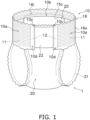
- FIG. 1 is a front view of a state of wearing of a refastenable wearable article 1.
- FIG. 2 is a rear view of the state of wearing of the wearable article 1.
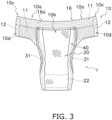
- FIG. 3 is a laid-out view of the wearable article 1 in an expanded state.
- FIG. 4 is an exploded perspective view of the wearable article 1.
- the wearable article 1 is a wearable article to which a stretchable sheet manufactured by a stretchable sheet manufacturing device 100 and a stretchable sheet manufacturing method according to one embodiment of the present invention is applied, the wearable article comprising an elastic waist-encircling member 10 worn on the body of a wearer.
- a stretchable sheet having an elastic member disposed between a pair of sheets is used as the waist-encircling member 10.
- the wearable article 1 is, in particular, a wearable article comprising a waist-encircling member 10 containing a stretchable sheet in which a weakening process has been performed on part of an elastic member (the elastic member has been partially cut).
- the stretchable sheet of the present invention can be widely applied to, for example, waist-encircling members, sleeve opening members, hem opening members, etc., in disposable diapers, disposable medical gowns, etc.
- the purpose of use of the stretchable sheet are not limited.
- a wearable article 1 which is a refastenable diaper, is used as an example to describe a wearable article comprising a stretchable sheet of the present invention.
- a summary of the structure and configuration of the wearable article 1 shall be briefly described, and the characteristic structure and configuration of the stretchable sheet of the present invention shall be described hereinafter.
- the wearable article 1 of the present embodiment has a structure and configuration similar to those of the wearable article disclosed in Patent Literature 1 ( Japanese Patent Publication No. 6903810 ) in many respects. Therefore, a detailed description of the wearable article 1 shall be omitted unless otherwise necessary.
- Waist-encircling direction implies a direction along the waist of a wearer when the wearable article 1 is worn by the wearer.
- the waist circumference orthogonal direction means a direction orthogonal to the waist-encircling direction and along a body length direction (height direction) of the wearer when the wearable article 1 is worn by the wearer.
- the refastenable wearable article 1 mainly comprises a waist-encircling member 10 disposed around the waist of the wearer, and an absorber 20 disposed from the back area of the wearer through the inseam area to the front abdomen, as shown in FIGS. 1 to 4 .
- the waist-encircling member 10 has a waist-encircling body 16 disposed around the waist of the wearer, and a male fastener 12 attached to the waist-encircling body 16, as shown in FIG. 3 .
- the waist-encircling body 16 is a member that is worn around the waist of the wearer and is capable of stretching in the waist-encircling direction.
- the stretchable sheet according to the present invention is used in the waist-encircling body 16.
- the waist-encircling body 16 mainly includes an inner sheet 14, an outer sheet 15, and an elastic member 11 disposed between the inner sheet 14 and the outer sheet 15, as shown in FIG. 4 .
- One of the inner sheet 14 and the outer sheet 15 is an example of a first sheet piece in the present invention, and the other of the inner sheet 14 and the outer sheet 15 is an example of a second sheet piece in the present invention.
- the inner sheet 14 is a sheet piece of, for example, nonwoven fabric.
- the inner sheet 14 is a band-form member extending in the waist-encircling direction.
- the inner sheet 14 has an inner surface 16i of the waist-encircling body 16 (see FIG. 4 ), which faces the skin of the wearer when the wearable article 1 is worn by the wearer.
- One end of the absorber 20 is joined to a portion of the inner sheet 14 that corresponds to an absorber joining part 10b (a portion of the inner surface 16i of the waist-encircling body 16 that corresponds to the absorber joining part 10b) which will be described later.
- the male fastener 12 is joined to a male fastener joining part 10d (which will be described later) of the inner sheet 14 (a portion of the inner surface 16i of the waist-encircling body 16 that corresponds to the male fastener joining part 10d).
- the outer sheet 15 is a sheet piece of, for example, nonwoven fabric.
- the outer sheet 15 is a band-form member extending in the waist-encircling direction.
- the outer sheet 15 has an outer surface 16o of the waist-encircling body 16 (see FIG. 4 ), which is disposed on the side opposite from the inner surface 16i of the waist-encircling body 16 and which faces outward (toward the side opposite of the skin of the wearer) when the wearable article 1 is worn by the wearer.
- the elastic member 11 is a member that is disposed between the inner sheet 14 and the outer sheet 15 and that has elasticity so as to stretch in the waist-encircling direction, as in FIG. 4 .
- the elastic member 11 In the manufactured wearable article 1, the elastic member 11 is in a stretched state, and restoring force acts on the elastic member 11 in a direction of contraction in the waist-encircling direction. Due to the waist-encircling body 16 having the elastic member 11, the waist-encircling body 16 can be caused to fit tightly to the waist of the wearer by the restoring force of the elastic member 11 when the wearer wears the wearable article 1.
- the elastic member 11 is formed of, for example, polyurethane, natural rubber, thermoplastic resin, or another material.
- the shape of the elastic member 11 is thread-form in the present embodiment.
- a plurality of thread-form elastic members 11 extending in the waist-encircling direction are disposed between the inner sheet 14 and the outer sheet 15 (see FIGS. 1 to 4 ).
- the elastic member 11 is partially joined to at least one of the inner sheet 14 and the outer sheet 15.
- the elastic member 11 is a portion facing the inner sheet 14, and is disposed in an area of the waist-encircling body 16 excluding the absorber joining part 10b and end part 10c which will be described later, as shown in FIG. 4 .
- the elastic member 11 is cut by the weakening process in the process of manufacturing the wearable article 1, as shown in FIGS. 3 and 4 .
- the waist-encircling body 16, in which the inner sheet 14, the outer sheet 15, and the elastic member 11 are integrated, includes the absorber joining part 10b and two side parts 10a disposed on both sides of the absorber joining part 10b in the waist-encircling direction of the wearer, as shown in FIG. 3 .
- the absorber joining part 10b is a portion to which the absorber 20 is joined.
- the absorber joining part 10b is a center part of the waist-encircling body 16 in the waist-encircling direction, and is positioned in a lower part of the waist-encircling body 16 in the waist circumference orthogonal direction (at the side disposed at the bottom when the wearer is standing while wearing the wearable article 1).
- the elastic member 11 is not present. Alternatively, as a result of the weakening process, the elastic force of the elastic member 11 does not substantially act on the absorber joining part 10b.
- the elastic member 11 is disposed at the upper part of the waist-encircling body 16 in the waist circumference orthogonal direction of the absorber joining part 10b (at the upper part of the absorber joining part 10b when the wearer is standing while wearing the wearable article 1).
- the waist-encircling body 16 can be caused to fit tightly to the waist of the wearer by the restoring force of the elastic member 11 when the wearer wears the wearable article 1.
- Each of the two side parts 10a of the waist-encircling body 16 is a portion that extends in the waist-encircling direction from a position on the absorber joining part 10b to the end part 10c of the side part 10a in a direction away from the absorber joining part 10b.
- the two end parts 10c are the end parts of the waist-encircling body 16 in the waist-encircling direction.
- the side parts 10a are members that cover left and right side surfaces and a front surface of the waist of the wearer when the wearer wears the wearable article 1.
- a male fastener 12 is joined to each of the two end parts 10c of the waist-encircling body 16.
- the male fasteners 12 work with a female fastener 22, which will be described later, in combination to function as a surface fastener. More specifically, the male fasteners 12 are joined to the inner surface 16i of the waist-encircling body 16 (the surface facing the wearer-skin-side of the inner sheet 14) at the end parts 10c of the waist-encircling body 16.
- the portions of the waist-encircling body 16 where the male fasteners 12 are joined are referred to as male fastener joining parts 10d.
- the absorber 20 is a member for absorbing urine and other body fluids.
- the absorber 20 mainly has a core 25, a topsheet 24, an undersheet 26, the female fastener 22, leg gathers 31, and three-dimensional gathers 40.
- the core 25 includes a nonwoven fabric carrying a highly absorbent polymer, and has the function of absorbing urine and other body fluids.
- the topsheet 24 is a member provided on the wearer-skin-side of the core 25.
- the topsheet 24 is a sheet-form member made of one piece of nonwoven fabric, or a sheet-form member formed by layering multiple pieces of nonwoven fabric.
- the undersheet 26 is a sheet-form member provided to the core 25 on the side opposite (outer surface side) from the wearer-skin-side so that the core 25 is sandwiched between the undersheet 26 and the topsheet 24.
- the undersheet 26 includes a liquid-impermeable sheet 26a, which is a nonwoven fabric made of polypropylene, polyethylene, or the like, and an exterior sheet 26b that covers the outside of the liquid-impermeable sheet 26a.
- the liquid-impermeable sheet 26a is a member that is water repellent and that prevents the passage of urine and other body fluids.
- the female fastener 22 which works with the male fasteners 12 of the waist-encircling body 16 in combination to function as a surface fastener, is attached to an outer surface of the undersheet 26 (the surface opposite from the wearer-skin-side of the exterior sheet 26b).
- the leg gathers 31 are elastic members that are disposed at positions corresponding to the groin when the wearer wears the wearable article 1.
- the leg gathers 31 are provided along both edges of the liquid-impermeable sheet 26a in the waist-encircling direction and over substantially the entire liquid-impermeable sheet 26a in the waist circumference orthogonal direction when the wearable article 1 is laid out as shown in FIG. 3 .
- the leg gathers 31 are disposed between the liquid-impermeable sheet 26a and the topsheet 24 in a stretched state in the waist circumference orthogonal direction when the wearable article 1 is laid out as shown in FIG. 3 .
- the three-dimensional gathers 40 are provided on a surface of the topsheet 24 facing the skin-surface side, as shown in FIG. 4 .
- the three-dimensional gathers 40 elastically fit tightly to the back, crotch, front abdomen, etc., of the wearer, and suppress the outflow of urine and other body fluids to the outside of the wearable article 1.
- the absorber 20 is joined to the absorber joining part 10b of the waist-encircling body 16, as shown in FIGS. 3 and 4 .
- the absorber 20 extends in the waist circumference orthogonal direction from the absorber joining part 10b, in a direction away from the waist-encircling body 16, as shown in FIG. 3 .
- the absorber 20 is disposed from the back of the wearer through the inseam to the front abdomen.
- the aforementioned female fastener 22 is attached to the outer surface that faces the side opposite from the wearer when the wearer wears the wearable article 1.
- the wearable article 1 In an assembled state (at the stage where the wearable article is used), the wearable article 1 is deformed such that the absorber 20 is folded back so that the topsheet 24 is disposed on the inner side, and the surfaces on the sides where the male fasteners 12 are disposed in at least the end parts 10c of the side parts 10a of the waist-encircling body 16 overlap the exterior sheet 26b of the undersheet 26 of the absorber 20.
- the male fasteners 12 of the waist-encircling body 16 are caused to engage the female fastener 22 attached to the exterior sheet 26b of the absorber 20, as shown in FIGS. 1 and 2 .
- the wearer of the wearable article 1 pushes open the waist-encircling member 10 of the refastenable wearable article 1 assembled in underpants form with the male fasteners 12 and the female fastener 22 engaged, and inserts their legs to wear the wearable article 1 like underpants.
- the stretchable sheet manufacturing device 100 which constitutes part of the device 1000 for manufacturing the wearable article 1, is a device that forms a hereinafter-described stretchable sheet continuous body 116.
- the stretchable sheet manufacturing device 100 mainly includes a forming device 200 and cutting device 300 which will be described later.
- a characteristic configuration and method of the stretchable sheet manufacturing device 100 of the present embodiment shall be described hereinafter.
- the device 1000 for manufacturing the wearable article 1 and the method for manufacturing the wearable article 1 are similar to the wearable article manufacturing device and manufacturing method disclosed in Patent Literature 1 ( Japanese Patent Publication No. 6903810 ). Therefore, unless particularly necessary, detailed descriptions of the device 1000 for manufacturing the wearable article 1 and the method for manufacturing the wearable article 1 shall be omitted.
- a direction in which sheets or the like are conveyed in each step is referred to as an MD direction
- a direction orthogonal to the MD direction is referred to as a CD direction.
- Step P1 and step P2 in FIG. 5 are examples of steps for manufacturing the stretchable sheet continuous body 116, in which a plurality of waist-encircling bodies 16 are continuous.
- a continuous body 115 of a sheet in which a plurality of outer sheets 15 are continuous is conveyed in the MD direction, and on the continuous body 115, continuous elastic members 11 in a stretched state are disposed in a straight line along the MD direction, as shown in FIG. 5 .
- a plurality of continuous elastic members 11 are disposed at intervals in the waist circumference orthogonal direction (CD direction) on the continuous body 115.
- a continuous body 114 in which a plurality of inner sheets 14 are continuous is conveyed in the MD direction, and the continuous body 114 is disposed on the continuous body 115 so as to cover the elastic members 11 from above, as shown in FIG. 5 .
- the forming device 200 which is an example of a former, joins the elastic member 11 to at least one of the continuous body 115 and the continuous body 114.
- the forming device 200 joins the elastic member 11 to at least one of the continuous body 115 and the continuous body 114 by ultrasonic welding.
- the joining method used by the forming device 200 may be welding using heat sealing.
- a continuous body in which the continuous body 114, the elastic member 11, and the continuous body 115 are laminated and integrated by joining is hereinafter referred to as the stretchable sheet continuous body 116.
- step P2 the weakening process is carried out on the elastic member 11 in positions of the stretchable sheet continuous body 116 corresponding to the absorber joining part 10b where the absorber 20 is disposed and the male fastener joining parts 10d where the male fasteners 12 are disposed.
- the weakening process is a process in which the elastic member 11 of the stretchable sheet continuous body 116 is cut by the cutting device 300.
- the cutting device 300 may be a gather cutter that cuts the elastic member 11 using a blade, or may be an embossing roll (heat embossing) device that applies heat to melt and cut the elastic member 11.
- Steps P3 to P7 are an example of steps for manufacturing the absorber 20.
- a partially processed topsheet is formed in which a continuous body of topsheets 24 in which a plurality of topsheets 24 are continuous and a continuous body of three-dimensional gathers 40 in which a plurality of three-dimensional gathers 40 are continuous are combined.
- step P4 a continuous body of cores 25 in which a plurality of cores 25 are continuous is formed, and a core 25 is manufactured using the continuous body of cores 25.
- step P5 a partially processed undersheet is formed in which a continuous body of undersheets 26 and a continuous body of leg gathers 31 are joined together
- step P6 a partially processed absorber is formed in which the partially processed topsheet formed in step P3, the core 25 formed in step P4, and the partially processed undersheet formed in step P5 are combined.
- step P7 the partially processed absorber formed in step P6 is cut, and individual absorbers 20 are manufactured.
- Steps P8 to P11 are an example of steps for assembling the wearable article 1.
- one end part (the end part on the side opposite from the female fastener 22) of the 90°-inverted absorber 20 manufactured in step P7 is disposed on the absorber joining parts 10b of the waist-encircling bodies 16 in the stretchable sheet continuous body 116 manufactured in step P2.
- the absorber 20 is joined to the inner surfaces 16i of the waist-encircling bodies 16 at positions corresponding to the absorber joining parts 10b.
- the joining means may be adhesion using a hot melt adhesive, thermal welding using a heat sealing device, or ultrasonic welding using an ultrasonic welding device.
- step P9 a portion (referred to as an extended part 15c, see FIG. 4 ) of the continuous body 115 of the outer sheets 15 of the stretchable sheet continuous body 116 that does not have the elastic member 11 disposed thereon and that is not covered by the continuous body 114 of the inner sheets 14 is folded back.
- the extended part 15c is joined to the absorbers 20 in a state of covering the end parts on the absorber joining parts 10b of the absorbers 20 (the end parts joined to the stretchable sheet continuous body 116).
- the male fasteners 12 are joined to portions of the waist-encircling bodies 16 that correspond to the male fastener joining parts 10d.
- the joining means in this embodiment may be adhesion using a hot melt adhesive, welding using heat sealing, or ultrasonic welding.
- step P10 the absorbers 20 are folded in two in the CD direction by two folding devices 54.
- step P11 the stretchable sheet continuous body 116 is cut in the CD direction by a cutter 56 at a position that is a midpoint between adjacent absorbers 20 and a midpoint between the male fasteners 12 in the MD direction.
- the stretchable sheet continuous body 116 and a plurality of absorbers 20 are thereby separated into individual waist-encircling bodies 16 and individual absorbers 20 joined thereto.
- step P12 the side parts 10a disposed on both sides of the waist-encircling member 10 in the MD direction are folded back toward the absorber joining part 10b of the waist-encircling member 10 so that the male fasteners 12 of both end parts 10c face the outer surface of the absorber 20.
- the male fasteners 12 of the waist-encircling member 10 and the female fastener 22 of the absorber 20 are then engaged with each other.
- FIG. 6 is a diagram schematically depicting the forming device 200.
- FIG. 7 is a schematic depiction of the forming device 200, in which part of an external peripheral surface 211 of an anvil roll 210 is laid out in planar form.
- FIG. 8 includes a drawing of a second groove formation portion 216 (part of a second protrusion 212b) enclosed within circle ⁇ in FIG. 7 , as seen along a radial direction of the anvil roll 210, and a cross-sectional view of the second groove formation portion 216 along arrow X1-X1 in said drawing.
- FIG. 9 includes a drawing of a first groove formation portion 214 (part of a first width-direction protrusion 212aa) enclosed within circle ⁇ in FIG. 7 , as seen along a circumferential direction of the anvil roll 210, and a cross-sectional view of the first groove formation portion 214 along arrow X2-X2 in said drawing.
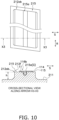
- FIG. 10 includes a drawing of a first groove formation portion 215 (a first circumferential-direction protrusion 212ab) enclosed within ellipse ⁇ in FIG. 7 , as seen along the radial direction of the anvil roll 210, and a cross-sectional view of the first groove formation portion 215 along arrow X3-X3 in said drawing.
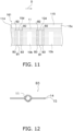
- FIG. 11 is a drawing schematically depicting a stretchable sheet continuous body 116 formed by the stretchable sheet manufacturing device 100 (the forming device 200 and the cutting device 300).
- FIG. 12 is a partial cross-sectional view of the area indicated by B3 (third area B3) in FIG. 11 , sectioned in a direction orthogonal to a conveyance direction D (a waist-encircling direction when the continuous body is formed on a wearable article 1) of the stretchable sheet continuous body 11.
- B3 third area B3
- FIGS. 6 to 13 are drawings for explanatory purposes, and do not accurately represent the actual dimensions and shapes of each component. In addition, in order to avoid the drawings becoming complicated, some reference numerals are omitted in FIGS. 6 to 13 .
- the forming device 200 is an example of a former, and forms the stretchable sheet continuous body 116 in which the continuous body 114 which is an example of a continuous first sheet, the continuous body 115 which is an example of a continuous second sheet, and the continuous elastic member 11 disposed between the continuous body 114 and the continuous body 115, are integrated.
- the forming device 200 mainly has the anvil roll 210 which is an example of a first joining member, an introduction device 220, and an ultrasonic horn 230 which is an example of a second joining member (see FIG. 6 ).
- the ultrasonic horn 230 vibrates due to ultrasonic waves generated by an oscillator (not shown).
- the anvil roll 210 is a member that supports the continuous body 114, the elastic member 11, and the continuous body 115, which are conveyed in the conveyance direction D (see the arrow in FIG. 6 ).
- the introduction device 220 introduces the elastic member 11 into the anvil roll 210 while guiding the elastic member 11.
- the continuous body 115 is introduced into the anvil roll 210 upstream of the introduction device for the elastic member 11 in a rotation direction of the anvil roll 210.
- the continuous body 114 is introduced into the anvil roll 210 downstream of the introduction device for the elastic member 11 in the rotation direction of the anvil roll 210.
- the anvil roll 210 conveys the pair of continuous bodies 115, 114 and the elastic member 11 such that the elastic member 11 is disposed between the pair of continuous bodies 115, 114.
- the ultrasonic horn 230 sandwiches the continuous body 114, the elastic member 11, and the continuous body 115.
- the ultrasonic horn 230 operates in cooperation with the anvil roll 210 to partially join (ultrasonically weld) the pair of continuous bodies 115, 114.
- the ultrasonic horn 230 also operates in cooperation with the anvil roll 210 to partially join at least one of the pair of continuous bodies 115, 114 to the elastic member 11, causing the elastic member 11 to be held by the pair of continuous bodies 115, 114.
- the second joining member according to the present invention is not limited to the ultrasonic horn 230 and may be, inter alia, a roll having a built-in heater for thermally welding the continuous bodies 115, 114 to each other or the continuous bodies 115, 114 to the elastic member 11.
- the anvil roll 210 shall now be described in greater detail.
- the anvil roll 210 is a cylindrical member that rotates around an axis, and has numerous protrusions 212 that protrude radially outward from the anvil roll 210 on the external peripheral surface 211, as shown in FIGS. 6 and 7 .
- the external peripheral surface 211 of the anvil roll 210 is an example of a facing surface of the anvil roll 210 serving as the first joining member, which faces the ultrasonic horn 230 serving as the second joining member.
- the protrusions 212 each have a first surface 212f that faces the ultrasonically vibrating ultrasonic horn 230 (see FIG. 6 ).
- the first surfaces 212f for example, protrude outward in the radial direction of the anvil roll 210 by a certain height h from the external peripheral surface 211 of the anvil roll 210, as shown in FIGS. 8 to 10 .
- the continuous body 115 and the continuous body 114 and sandwiched and pressurized between the first surfaces 212f of the protrusions 212 and the ultrasonically vibrating ultrasonic horn 230, whereby the continuous body 115 and the continuous body 114 are ultrasonically welded.
- the protrusions 212 are set apart from each other in the circumferential direction R of the anvil roll 210, as shown in FIG. 7 .
- One or more grooves G extending in the circumferential direction R of the anvil roll 210 are formed on the first surfaces 212f of the protrusions 212.
- the grooves G extend along the conveyance direction D of the continuous body 114, the elastic member 11, and the continuous body 115 supported and conveyed by the anvil roll 210.
- the grooves G are grooves into which, among the continuous body 114, the elastic member 11, and the continuous body 115 supported and conveyed by the anvil roll 210, the continuous body 115 and the elastic member 11 are fitted.
- the grooves G provided on the first surfaces 212f of the protrusions 212 are disposed in a linear alignment with the grooves G provided on the adjacent protrusions 212 along the circumferential direction R of the anvil roll 210, as shown in FIG. 7 . Therefore, the elastic member 11 introduced into the anvil roll 210 by the introduction device 220 are guided by the linearly aligned grooves G and conveyed along the circumferential direction R of the anvil roll 210.
- the protrusions 212 include first protrusions 212a serving as an example of the first parts in the claims, and second protrusions 212b serving as an example of the second parts in the claims.
- the first protrusions 212a include first width-direction protrusions 212aa and first circumferential-direction protrusions 212ab.
- the second protrusions 212b are provided in areas where first protrusions 212a are not provided in the circumferential direction R of the anvil roll 210. Specifically, in the circumferential direction R of the anvil roll 210, the second protrusions 212b are disposed on both sides of the areas where the first protrusions 212a are provided, adj acent to the areas where the first protrusions 212a are provided (see FIG. 7 ). In other words, in the conveyance direction D of the continuous body 114, the elastic member 11, and the continuous body 115 supported and conveyed by the anvil roll 210, the second protrusions 212b are disposed adjacent to upstream and downstream sides of the first protrusions 212a (see FIG. 7 ).
- the second protrusions 212b which are some of the protrusions 212, extend in a width direction S of the anvil roll 210 (the CD direction orthogonal to the MD direction in which the continuous bodies 114, 115 and the elastic member 11 are conveyed), as shown in FIG. 7 .
- the second protrusions 212b extend along a generating line parallel to an axial direction of the anvil roll 210.
- Two second protrusions 212b are disposed adjacent to the upstream side and downstream side of each first protrusion 212a in the conveyance direction D (see FIG. 7 ).
- the number of second protrusions 212b is merely an example; one or three or more second protrusions 212b may be disposed adjacent to the upstream side and downstream side of each first protrusion 212a in the conveyance direction D.
- each second protrusion 212b extending in the width direction S there are formed a plurality of grooves G that extend in the circumferential direction R of the anvil roll 210 and that are separated from each other in the width direction S of the anvil roll 210, as shown in FIG. 7 .
- the first circumferential-direction protrusions 212ab which are some of the protrusions 212, extend in the circumferential direction R of the anvil roll 210 (the MD direction in which the continuous bodies 114, 115 and the elastic member 11 are conveyed), as shown in FIG. 7 .
- One groove G extending in the circumferential direction R of the anvil roll 210 is formed in each first circumferential-direction protrusion 212ab extending in the circumferential direction R.
- Each first circumferential-direction protrusion 212ab may be divided into a plurality in the circumferential direction R of the anvil roll 210 instead of extending lengthwise in the circumferential direction R of the anvil roll 210.
- the first width-direction protrusions 212aa which are some of the protrusions 212, extend in the width direction S of the anvil roll 210 (the CD direction orthogonal to the MD direction in which the continuous bodies 114, 115 and the elastic member 11 are conveyed), as shown in FIG. 7 .
- the first width-direction protrusions 212aa extend along a generating line parallel to the axial direction of the anvil roll 210.
- One first width-direction protrusion 212aa is disposed adjacent to the upstream side and downstream side of each first circumferential-direction protrusion 212ab (between a first circumferential-direction protrusion 212ab and a second protrusion 212b) in the conveyance direction D (see FIG. 7 ).
- the number of the first width-direction protrusions 212aa is an example; two or more first width-direction protrusions 212aa may be disposed adjacent to the upstream side and downstream side of each first circumferential-direction protrusion 212ab in the conveyance direction D.
- the first width-direction protrusions 212aa may be omitted in another example.
- each first width-direction protrusion 212aa extending in the width direction S there are formed a plurality of grooves G that extend in the circumferential direction R of the anvil roll 210 and that are separated from each other in the width direction S of the anvil roll 210.
- the grooves G provided in the first protrusions 212a and the second protrusions 212b are disposed in linear alignment with the grooves G provided in the first protrusions 212a or second protrusions 212b that are adjacent along the circumferential direction R of the anvil roll 210, as shown in FIG. 7 .
- the continuous body 115 and the elastic member 11 fit into the grooves G of the plurality of protrusions 212 disposed along the circumferential direction R of the anvil roll 210, the grooves G being disposed in alignment in the circumferential direction R of the anvil roll 210 (disposed in the same position in the width direction S).
- the forming device 200 conveys the continuous body 114, the elastic member 11, and the continuous body 115 in the conveyance direction D in a state in which the continuous body 115 and the elastic member 11 are in the grooves G.
- the continuous body 115 and the elastic member 11 are in the grooves G, but this example is not provided by way of limitation; the continuous body 114 and the elastic member 11 may be in the grooves G (in other words, in the forming device 200, the continuous body 114, the elastic member 11, and the continuous body 115 may be conveyed with the continuous body 114 disposed on the inner side).
- the continuous body 114 and the continuous body 115 are conveyed along the external peripheral surface 211 of the anvil roll 210, and when the continuous body 114, the elastic member 11, and the continuous body 115 pass between the ultrasonic horn 230 and the protrusions 212, the ultrasonic horn 230 and the protrusions 212 of the anvil roll 210 sandwich the continuous body 114, the elastic member 11, and the continuous body 115 therebetween.
- the ultrasonic horn 230 also ultrasonically vibrates at this time.
- the continuous body 114 and the continuous body 115 which are sandwiched between the ultrasonic horn 230 and the first surfaces 212f of the protrusions 212 of the anvil roll 210 and are pressurized between the ultrasonic horn 230 and the first surfaces 212f of the protrusions 212 of the anvil roll 210, are joined (ultrasonically welded) together.
- the elastic member 11 is pressed by the ultrasonic horn 230 and the groove surfaces of the grooves G of the protrusions 212 of the anvil roll 210 via the continuous body 114 and the continuous body 115 at the time when the continuous body 114, the elastic member 11, and the continuous body 115 pass between the ultrasonic horn 230 and the protrusions 212 and the ultrasonic horn 230 is caused to ultrasonically vibrate, the continuous body 114 and the continuous body 115 are joined (ultrasonically welded) to the elastic member 11.
- the protrusions 212 of the anvil roll 210 include the first protrusions 212a and the second protrusions 212b as described above.
- the continuous body 114 and the continuous body 115 are not joined to the elastic member 11 between the ultrasonic horn 230 and the first protrusions 212a, but at least one of the continuous body 114 and the continuous body 115 is joined to the elastic member 11 between the ultrasonic horn 230 and the second protrusions 212b.
- the first protrusions 212a are parts that come into contact with portions that will become the male fastener joining parts 10d and with the outer sheet 15 surrounding these portions when the wearable article 1 is manufactured from the stretchable sheet continuous body 116 formed in the forming device 200.
- the first protrusions 212a form restricting parts 116b in the stretchable sheet continuous body 116 by sandwiching and pressurizing the continuous body 114 and the continuous body 115 between the first surfaces 212f and the ultrasonic horn 230 and joining the continuous body 114 and the continuous body 115 together.
- the continuous body 114 and the continuous body 115 are not joined to the elastic member 11.
- the restricting parts 116b, by the continuous body 114 and the continuous body 115 restrict the contraction movement of the elastic member 11 cut by the cutting device 300.
- the restriction of the contraction movement of the elastic member 11 by the continuous body 114 and the continuous body 115 means not that the continuous body 114 and the continuous body 115 do not allow contraction movement of the elastic member 11 (the elastic member 11 does not contract), but rather that the continuous body 114 and the continuous body 115 restrict (suppress) momentum of the contraction movement of the elastic member 11.
- the elastic member 11 cut by the cutting device 300 contracts more slowly than if the restricting parts 116b were not present.
- the elastic member 11 For restricting the contraction movement of the elastic member 11 with the restricting parts 116b, the elastic member 11 is in a state of being compressed by the continuous body 114 and the continuous body 115 in the restricting parts 116b, specifically.
- the restricting parts 116b of the stretchable sheet continuous body 116 have spaces to accommodate the elastic member 11 enclosed by the continuous body 114 and the continuous body 115, and in these spaces are portions where a maximum gap between the formed continuous body 114 and the continuous body 115 is smaller than a diameter of the elastic member 11 while tension is not being applied.
- the second protrusions 212b are parts that come into contact with the outer sheet 15 nearer to the absorber joining part 10b than the male fastener joining parts 10d in the waist-encircling direction when the wearable article 1 is manufactured from the stretchable sheet continuous body 116 formed in the forming device 200.
- the first protrusions 212a and the second protrusions 212b preferably have configurations such as the following.
- the second protrusions 212b have a plurality of second groove formation portions 216 (see FIG. 8 ) extending farther in the circumferential direction R of the anvil roll 210 than other portions of the second protrusions 212b, such as is depicted in circle ⁇ in FIG. 7 .
- the plurality of second groove formation portions 216 are spaced apart from each other in the width direction S of the anvil roll 210.
- second grooves 216a (grooves G) (see FIG. 8 ) into which, of the continuous body 114, the elastic member 11, and the continuous body 115 conveyed in the conveyance direction D, the continuous body 115 and the elastic member 11 enter.
- the second grooves 216a are V-shaped as in FIG. 8 .
- a depth of the second grooves 216a is smaller than a sum (first sum value) of the diameter of the elastic member 11 and a thickness of the continuous body 115 conveyed while under tension in the forming device 200.
- the elastic member 11 conveyed on the second grooves 216a of the second groove formation portions 216 is in a state of protruding at least partially from the second grooves 216a outward in the radial direction of the anvil roll 210, as in the cross-sectional view in FIG. 8 . Therefore, when the continuous body 114, the elastic member 11, and the continuous body 115 are sandwiched between the ultrasonic horn 230 and the second groove formation portions 216 of the second protrusions 212b, the elastic member 11 is pressurized between the ultrasonic horn 230 and the second groove formation portions 216 via the continuous body 114 and the continuous body 115, and the continuous body 114 and the continuous body 115 are joined to the elastic member 11.
- the first width-direction protrusions 212aa have a plurality of first groove formation portions 214 extending farther in the circumferential direction R of the anvil roll 210 than other portions of the first width-direction protrusions 212aa, as is depicted in circle ⁇ in FIG. 7 .
- the plurality of first groove formation portions 214 are spaced apart from each other in the width direction S of the anvil roll 210.
- the first width-direction protrusions 212aa have first groove formation portions 214 shaped as described below at least in positions corresponding to the first circumferential-direction protrusions 212ab in the width direction S of the anvil roll 210.
- first grooves 214a (grooves G) into which, of the continuous body 114, the elastic member 11, and the continuous body 115 conveyed in the conveyance direction D, the continuous body 115 and the elastic member 11 enter.
- first grooves 214a are U-shaped as in FIG. 9 .
- a depth of the first grooves 214a is larger than the sum (first sum value) of the diameter of the elastic member 11 and the thickness of the continuous body 115 conveyed while under tension in the forming device 200.
- the elastic member 11 conveyed on the first grooves 214a of the first groove formation portions 214 is in a state of being entirely accommodated in the first grooves 214a.
- the elastic member 11 when the continuous body 114, the elastic member 11, and the continuous body 115 are sandwiched between the ultrasonic horn 230 and the first groove formation portions 214 of the first width-direction protrusions 212aa, the elastic member 11 is not pressurized between the ultrasonic horn 230 and the bottom surfaces of the first grooves 214a of the first groove formation portions 214, and the continuous body 114 and the continuous body 115 are not joined to the elastic member 11.
- the depth of the first grooves 214a is preferably smaller than a sum (second sum value) of the diameter of the elastic member 11 and the thickness of the continuous body 115 in a state in which tension is not applied.
- a width of the first grooves 214a (a dimension in the width direction S of the anvil roll 210) is greater than a sum (third sum value) of the diameter of the elastic member 11 being conveyed through the forming device 200 in the conveyance direction D and twice the thickness of the continuous body 115, and is smaller than a sum (fourth sum value) of the diameter of the elastic member 11 and twice the thickness of the continuous body 115 while tension is not applied.
- the elastic member 11 when the elastic member 11 is partially cut as described below and the elastic member 11 acts as though to return to the original state (the natural length while not under tension) due to restoring force, the diameter of the elastic member 11 becomes larger than the diameter while stretching. Therefore, the elastic member 11 is subjected to pressure by the continuous body 114 and the continuous body 115, and the contraction movement of the elastic member 11 is restricted by the friction force between the elastic member 11 and at least one of the continuous body 114 and the continuous body 115.
- the first circumferential-direction protrusions 212ab each have a first groove formation portion 215 (see FIG. 10 ) that protrudes outward in the radial direction of the anvil roll 210 to the same height h as the first width-direction protrusions 212aa, as depicted in ellipse ⁇ in FIG. 7 .
- the first groove formation portions 215 differ from the first groove formation portions 214 by extending farther in the circumferential direction R of the anvil roll 210 than the first groove formation portions 214, but a cross-sectional shape of a first groove 215a formed in each first groove formation portion 215 is similar to that of the first grooves 214a (see FIG. 10 ).
- the first grooves 215a and the first grooves 214a serve similar purposes. The details of the first groove formation portions 215 and the first grooves 215a shall not be described here.
- the cutting device 300 cuts the elastic member 11 of the stretchable sheet continuous body 116 in the CD direction, which is orthogonal to the MD direction of the stretchable sheet continuous body 116.
- the cutting device 300 cuts the elastic member 11 of the stretchable sheet continuous body 116 at center portions of the restricting parts 116b formed by the first protrusions 212a (the first circumferential-direction protrusions 212ab and the first circumferential-direction protrusions 212ab) in the waist-encircling direction (in the MD direction of the stretchable sheet continuous body 116).
- the elastic member 11 moves at a relatively slow speed toward the fixed parts 116a adjacent to the restricting parts 116b in a state in which the contraction movement of the elastic member 11 is restricted by the restricting parts 116b, thereby forming one of the male fastener joining parts 10d of the waist-encircling body 16 manufactured from the stretchable sheet continuous body 116 conveyed downstream of the cutting device in the conveyance direction D, and one of the male fastener joining parts 10d of the waist-encircling body 16 manufactured from the stretchable sheet continuous body 116 conveyed upstream of the cutting device in the conveyance direction D.
- FIG. 11 depicts a stretchable sheet continuous body 116 in which the elastic member 11 is partially cut by the cutting device 300 and absorber joining parts 10b and male fastener joining parts 10d are formed.
- first areas B1 that will become the first portions of the claims and third areas B3 that will become the third portions of the claims are formed in and around the male fastener joining parts 10d of the stretchable sheet continuous body 116 when the stretchable sheet continuous body 116 is applied to the waist-encircling body 16 as a stretchable sheet.
- second areas B2 that will become the second portions of the claims are formed around the stretchable sheet continuous body 116 when the stretchable sheet continuous body 116 is applied to the waist-encircling body 16 as a stretchable sheet.
- the first areas B1 are portions where the elastic member 11 is not present as a result of the elastic member 11 contracting.
- the elastic member 11 is joined to at least one of the continuous body 114 and the continuous body 115 (both in this embodiment).
- the third areas B3 are portions disposed between the first areas B1 and the second areas B2.
- Each first area B1 includes a portion where, in a cross-sectional view sectioned in a direction orthogonal to the waist-encircling direction (generally, a first direction in which the elastic member 11 extends) (i.e., a cross-sectional view sectioned in a direction orthogonal to the conveyance direction D of the stretchable sheet continuous body 116) as in FIG. 13 , a maximum gap of a space between the inner sheet 14 and the outer sheet 15, which communicates with a space in the second area B2 where the elastic member 11 is placed, is smaller than the diameter of the elastic member 11 (depicted by the double-dash line in FIG. 13 ) while tension is not being applied (the natural length).
- each third area B3 includes a portion where, in a cross-sectional view sectioned in the direction orthogonal to the waist-encircling direction as in FIG. 12 , the maximum gap of the space between the inner sheet 14 and the outer sheet 15, which communicates with the space in the second area B2 where the elastic member 11 is placed, is smaller than the diameter of the elastic member 11 (depicted by the double-dash line in FIG. 12 ) while tension is not being applied (the natural length).
- the maximum gap of the space between the inner sheet 14 and the outer sheet 15 (referred to here as an elastic member placement space), which communicates with the space in the second area B2 where the elastic member 11 is placed, is smaller than the diameter of the elastic member 11 while tension is not being applied (the natural length).
- the cutting device 300 cuts the elastic member 11 and the elastic member 11 contracts and is thereby becoming absent in the elastic member placement space where the elastic member 11 had originally been placed in the first area B1
- the contraction speed of the elastic member 11 can be reduced by sliding friction force generated between the elastic member 11 and at least one of the inner sheet 14 (continuous body 114) and the outer sheet 15 (continuous body 115).
- the contraction speed of the elastic member 11 can be reduced by sliding friction force generated between the elastic member 11 and at least one of the inner sheet 14 (continuous body 114) and the outer sheet 15 (continuous body 115).
- a stretchable sheet manufacturing device 100 of the present embodiment comprises a forming device 200 serving as an example of a former, and a cutting device 300 serving as an example of a cutter.
- the forming device 200 forms a stretchable sheet continuous body 116 in which a continuous body 114 that is continuous, a continuous body 115 that is continuous, and an elastic member 11 that is continuous and is disposed between the continuous body 114 and the continuous body 115 are integrated.
- the cutting device 300 cuts the elastic member 11 of the stretchable sheet continuous body 116.
- the forming device 200 has an anvil roll 210 serving as an example of a first joining member, and an ultrasonic horn 230 serving as an example of a second joining member.
- the anvil roll 210 supports the continuous body 114, the elastic member 11, and the continuous body 115, which are conveyed in a conveyance direction D.
- the ultrasonic horn 230 together with the anvil roll 210, sandwiches the continuous body 114, the elastic member 11, and the continuous body 115.
- the anvil roll 210 has a first protrusion 212a serving as an example of a first part and a second protrusion 212b serving as an example of a second part in an external peripheral surface 211 serving as an example of a facing surface that faces the ultrasonic horn 230 serving as an example of the second joining member.
- the second protrusion 212b is disposed adjacent to the first protrusion 212a in the conveyance direction D.
- the ultrasonic horn 230 forms a restricting part 116b in the stretchable sheet continuous body 116 by sandwiching the elastic member 11, the continuous body 114, and the stretchable sheet continuous body 116 between the ultrasonic horn 230 and the first protrusion 212a of the anvil roll 210 to join the continuous body 114 and the continuous body 115 together.
- the ultrasonic horn 230 forms a fixed part 116a in the stretchable sheet continuous body 116 by sandwiching the elastic member 11, the continuous body 114, and the continuous body 115 between the ultrasonic horn 230 and the second protrusion 212b of the anvil roll 210 to join at least one of the continuous body 114 and the continuous body 115 to the elastic member 11.
- the cutting device 300 cuts the elastic member 11 of the conveyed stretchable sheet continuous body 116 in the restricting part 116b of the stretchable sheet continuous body 116.
- the continuous body 114 and the continuous body 115 are not joined to the elastic member 11.
- contraction movement of the elastic member 11 cut by the cutting device 300 is restricted by the continuous body 114 and the continuous body 115.
- the incidence of adverse events in which the joining of the sheets and the elastic member 11 in the stretchable sheet continuous body 116 comes undone can be suppressed.
- the first protrusion 212a of the anvil roll 210 includes first groove formation portions 214, 215, and the second protrusion 212b of the anvil roll 210 includes a second groove formation portion 216.
- a depth of the first grooves 214a, 215a is greater than a first sum value, which is a sum of a diameter of the elastic member 11 and a thickness of the continuous body 115 being conveyed through the forming device 200 in the conveyance direction D.
- a depth of the second groove 216a is less than the first sum value.
- this device 100 for manufacturing a wearable article 1 it is possible to suppress the incidence of events in which, in the restricting part 116b, the elastic member 11 is joined to the continuous body 114 or the continuous body 115 and an elastic force of the elastic member 11 remains in a portion of the stretchable sheet continuous body 116 where the weakening process is to be performed.
- a depth of the first grooves 214a, 215a is less than a second sum value, which is a sum of the diameter of the elastic member 11 and the thickness of the continuous body 115 while tension is not being applied.
- a width of the first grooves 214a, 215a in a width direction S of the anvil roll 210 is greater than a third sum value, which is a sum of the diameter of the elastic member 11 and twice the thickness of the continuous body 115 being conveyed through the forming device 200 in the conveyance direction D.
- the width of the first grooves 214a, 215a in the width direction of the anvil roll 210 is less than a fourth sum value, which is a sum of the diameter of the elastic member 11 and twice the thickness of the continuous body 115 while tension is not being applied.
- this device 100 for manufacturing a wearable article 1 it is possible to suppress the incidence of events in which the first grooves 214a, 215a inhibit the conveying of the elastic member 11 and the continuous body 115. Moreover, in this device 100 for manufacturing a wearable article 1, rapid contraction movement of the elastic member 11 is restricted by the continuous body 114 and the continuous body 115 when the elastic member 11 is cut, and it is possible to suppress the incidence of adverse events in which the joining of the elastic member 11 with the continuous body 114 and/or the continuous body 115 comes undone in a fixed part 116a.
- a method for manufacturing a wearable article 1 of the present embodiment comprises a forming step and a cutting step.
- a continuous body 114 that is continuous, a continuous body 115 that is continuous, and an elastic member 11 that is continuous and is disposed between the continuous body 114 and the continuous body 115 are integrated, and a stretchable sheet continuous body 116 is formed.
- the cutting step the elastic member 11 of the stretchable sheet continuous body 116 is cut.
- the forming step includes a conveying step, a first forming step, and a second forming step.
- the continuous body 114, the continuous body 115, and the elastic member 11 are conveyed in a conveyance direction D in a state in which the elastic member 11 has been disposed between the continuous body 114 and the continuous body 115.
- the elastic member 11, the continuous body 114, and the continuous body 115 conveyed in the conveyance direction D are sandwiched between an anvil roll 210, which is an example of a first joining member that supports the continuous body 114, the elastic member 11, and the continuous body 115, and an ultrasonic horn 230, which is an example of a second joining member, to join the elastic member 11 with at least one of the continuous body 114 and the continuous body 115, whereby a fixed part 116a is formed in the stretchable sheet continuous body 116.
- the elastic member 11, the continuous body 114, and the continuous body 115 are sandwiched between the anvil roll 210 and the ultrasonic horn 230 to join the continuous body 114 and the continuous body 115 together, whereby a restricting part 116b is formed in the stretchable sheet continuous body 116.
- the restricting part 116b of the stretchable sheet continuous body 116 is formed in a position adjacent to the fixed part 116a on the stretchable sheet continuous body 116.
- the elastic member 11 of the stretchable sheet continuous body 116 is cut in the restricting part 116b of the stretchable sheet continuous body 116.
- the continuous body 114 and the continuous body 115 are not joined to the elastic member 11.
- contraction movement of the elastic member 11 cut in the cutting step is restricted by the continuous body 114 and the continuous body 115.
- a wearable article 1 of the present embodiment is a wearable article comprising a stretchable sheet.
- a stretchable sheet manufactured by the stretchable sheet manufacturing device 100 is applied to a waist-encircling member 10 disposed around a waist of a wearer.
- the stretchable sheet applied to the waist-encircling member 10 includes at least an inner sheet 14, and outer sheet 15, and an elastic member 11.
- the elastic member 11 extends in a first direction (a waist-encircling direction along the waist of the wearer in the present embodiment), and is disposed between the inner sheet 14 and the outer sheet 15.
- the stretchable sheet applied to the waist-encircling member 10 includes, in the first direction, a first portion (first area B1) and a second portion (second area B2).
- the elastic member 11 is not present in the first area B1.
- the elastic member 11 is joined to at least one of the inner sheet 14 and the outer sheet 15.
- the first area B1 there is a portion where, in a cross-sectional view sectioned in a direction orthogonal to the first direction, a maximum gap of a space between the inner sheet 14 and the outer sheet 15, which communicates with a space in a third area B3 where the elastic member 11 is placed, is smaller than the diameter of the elastic member 11 while tension is not being applied (the natural length).
- the stretchable sheet applied to the waist-encircling member 10 includes a third portion (third area B3) disposed between the first area B1 and the second area B2 in a first direction (a waist-encircling direction along the waist of the wearer in the present embodiment).
- third portion there is a portion where, in a cross-sectional view sectioned in a direction orthogonal to the first direction, a maximum gap of a space between the inner sheet 14 and the outer sheet 15, which communicates with the space of the second area B2 where the elastic member 11 is placed, is smaller than the diameter of the elastic member 11 while tension is not being applied (the natural length).
- FIG. 14 is a diagram schematically depicting the forming device 200A.
- the forming device 200A has many similarities to the forming device 200 of the above embodiment, attributes where the forming device 200A is different from the forming device 200 shall mainly be described.
- the main difference in configuration between the forming device 200A and the forming device 200 is that the forming device 200A has two or more second joining members disposed along a conveyance direction D.
- the forming device 200A has, in addition to an ultrasonic horn 230 (farthest upstream second joining member), an ultrasonic horn 230A (farthest downstream second joining member) disposed downstream of the ultrasonic horn 230 in the conveyance direction D.
- the ultrasonic horn 230 and the ultrasonic horn 230A both, together with an anvil roll 210 serving as a first joining member, sandwich a continuous body 114, a continuous body 115, and an elastic member 11 conveyed in the conveyance direction D to join the continuous body 114 and the continuous body 115 together and join the elastic member 11 to at least one of the continuous body 114 and the continuous body 115.
- the ultrasonic horn 230 and the ultrasonic horn 230A may be, for example, horns for ultrasonic welding as depicted in FIG. 14 , or rolls having built-in heaters instead.
- the ultrasonic horn 230A serving as an example of a farthest downstream second joining member is disposed downstream of the ultrasonic horn 230 serving as an example of the farthest upstream second joining member in the conveyance direction D of the continuous body 114, the elastic member 11, and the continuous body 115.
- a position where the ultrasonic horn 230A and the anvil roll 210 face each other is disposed 180° away from a position where the ultrasonic horn 230 and the anvil roll 210 face each other in a circumferential direction of the anvil roll 210.
- FIG. 14 a position where the ultrasonic horn 230A and the anvil roll 210 face each other is disposed 180° away from a position where the ultrasonic horn 230 and the anvil roll 210 face each other in a circumferential direction of the anvil roll 210.
- an angle between the position where the ultrasonic horn 230A and the anvil roll 210 face each other and the position where the ultrasonic horn 230 and the anvil roll 210 face each other may be less than 180° or greater than 180° in the circumferential direction of the anvil roll 210.
- the main functional difference between the forming device 200A and the forming device 200 is that the forming device 200A joins the continuous body 114 and the continuous body 115 together and joins the elastic member 11 and at least one of the continuous body 114 and the continuous body 115 together in two stages; a temporary joining using the ultrasonic horn 230, and a permanent joining using the ultrasonic horn 230A.
- the elastic member 11 When the elastic member 11 is joined to at least one of the continuous body 114 and the continuous body 115, heat causes the elastic member 11 to decrease in strength, and there is a possibility that the elastic member 11 will be cut. If the elastic member 11 is cut, the restoring force of the elastic member 11 will cause the elastic member 11 to return to an upstream side in the conveyance direction, and it may be necessary to stop operation of the manufacturing device 100 in order to reposition the elastic member 11 between the continuous body 114 and the continuous body 115.
- the elastic member 11 is temporarily joined between the continuous body 114 and the continuous body 115 under conditions in which the elastic member 11 is unlikely to break, and then the elastic member 11 is firmly joined (permanently) joined between the continuous body 114 and the continuous body 115 by welding. Due to this configuration, even if the elastic member 11 is cut during the permanent joining, it is possible to suppress the incidence of events in which the elastic member 11 moves upstream in the conveyance direction at the location where the elastic member 11 is temporarily joined between the continuous body 114 and the continuous body 115.
- temporary joined refers to a state in which the joined members are joined to each other in a separable manner.
- temporary joined refers to a weak joined state in which materials are not broken up when the joined members are separated from each other.
- permanently joined refers to a state in which the joined members are joined to each other in an inseparable manner.
- permanently joined refers to a strong joined state in which, if the joined members were to be separated from each other, the material at least one of the members being separated would be broken up.
- seal strength between the ultrasonic horn 230A and the anvil roll 210 is set greater than seal strength between the ultrasonic horn 230 and the anvil roll 210.
- the ultrasonic horn 230A farthest downstream in the conveyance direction D, together with the anvil roll 210 sandwiches the temporary joined portion at a comparatively strong welding pressure (second welding pressure greater than the first welding pressure), and by ultrasonic welding, permanently joins the elastic member 11 to at least one of the continuous body 114 and the continuous body 115.
- the first welding pressure is 700 to 800 N
- the second welding pressure is 1250 N.
- the force with which the continuous body 114, the elastic member 11, and the continuous body 115 are sandwiched between the ultrasonic horns 230, 230A and the anvil roll 210 may be constant, and heater temperature may be set lower in the ultrasonic horn 230 and higher in the ultrasonic horn 230A.
- the stretchable sheet continuous body obtained from the permanent joining performed by the ultrasonic horn 230A may be the same as the stretchable sheet continuous body 116 described in the above embodiment.
- the characteristics of the forming device 200A are also useful in the manufacture of a stretchable sheet continuous body that does not have the fixed parts 116a and the restricting parts 116b described in the above embodiment. In other words, the characteristics of the forming device 200A are useful even if the forming device 200A does not have a configuration including the first protrusions 212a and the second protrusions 212b.
- a method for manufacturing a stretchable sheet in the forming device 200A shall now be described.
- This stretchable sheet manufacturing method comprises a forming step in which a continuous body 114 serving as an example of a first sheet that is continuous, a continuous body 115 serving as an example of a second sheet that is continuous, and an elastic member 11 that is continuous and is disposed between the continuous body 114 and the continuous body 115 are integrated to form a stretchable sheet continuous body 116.
- the forming step includes a conveying step, a first forming step, and a second forming step.
- the continuous body 114, the continuous body 115, and the elastic member 11 are conveyed in the conveyance direction D in a state in which the elastic member 11 has been disposed between the continuous body 114 and the continuous body 115.
- the elastic member 11, the continuous body 114, and the continuous body 115 conveyed in the conveyance direction D are sandwiched between an anvil roll 210 serving as an example of a first joining member that supports the continuous body 114, the elastic member 11, and the continuous body 115, and an ultrasonic horn 230 serving as an example of an upstream second joining member, and a temporary joined portion is formed in which the elastic member 11 is temporarily joined to at least one of the continuous body 114 and the continuous body 115.
- the temporary joined portion is sandwiched between the anvil roll 210 and an ultrasonic horn 230A serving as an example of a downstream second joining member to permanently join the elastic member 11 to at least one of the continuous body 114 and the continuous body 115 and form a stretchable sheet continuous body 116.
- the device 100 for manufacturing a wearable article 1 comprises a forming device 200A serving as an example of a former that forms a stretchable sheet continuous body 116 in which a continuous body 114 serving as an example of a first sheet that is continuous, a continuous body 115 serving as an example of a second sheet that is continuous, and an elastic member 11 that is continuous and is disposed between the continuous body 114 and the continuous body 115, are integrated.
- the forming device 200A has an anvil roll 210 serving as an example of a first joining member, and ultrasonic horns 230, 230A serving as examples of second joining members.
- the anvil roll 210 supports the continuous body 114, the elastic member 11, and the continuous body 115, which are conveyed in a conveyance direction D.
- Two or more (two in the present embodiment) second joining members are disposed along the conveyance direction D.
- this manufacturing device 100 it is possible to suppress the incidence of adverse events in which the elastic member 11 is cut during the joining of the elastic member 11 and at least one of the continuous body 114 and the continuous body 115, restoring force causes the elastic member 11 to be pulled back upstream, and the device 100 for manufacturing a wearable article 1 needs to be stopped in order to reposition the elastic member 11.
- the elastic member 11 and at least one of the continuous body 114 and the continuous body 115 are joined together in the temporary joined portion.
- the elastic member 11 and at least one of the continuous body 114 and the continuous body 115 need not be joined together in the temporary joined portion.
- the continuous body 114 and the continuous body 115 alone may be joined together by welding or the like, and the elastic member 11 need not be joined to the continuous body 114 or the continuous body 115.
- the diameter of the elastic member 11 increases when the elastic member 11 is cut back to the natural length thereof, and it is therefore possible to prevent the incidence of events in which the elastic member 11 is sandwiched at the joining location of the continuous body 114 and the continuous body 115 and the elastic member 11 contracts and moves upstream in the conveyance direction.
- the ultrasonic horn 230 and the ultrasonic horn 230A are disposed for one anvil roll 210 serving as a first joining member, but the configuration of the forming device is not limited to such a configuration.
- the forming device may have two or more first joining members disposed along the conveyance direction D.
- a forming device 200B may have an anvil roll 210A disposed farthest downstream in the conveyance direction D in addition to an anvil roll 210 disposed farthest upstream in the conveyance direction D.
- the ultrasonic horn 230 together with the anvil roll 210, sandwiches the continuous body 114, the elastic member 11, and the continuous body 115 to form a temporary joined portion in which the elastic member 11 and at least one of the continuous body 114 and the continuous body 115 are temporarily joined together.
- the ultrasonic horn 230A together with the anvil roll 210A, sandwiches the temporary joined portion to permanently join the elastic member 11 and at least one of the continuous body 114 and the continuous body 115 together and form a stretchable sheet continuous body 116.
- the anvil roll 210 and the anvil roll 210A have protrusions 212 in the same pattern in the external peripheral surfaces 211, and the forming device 200B is designed such that the continuous body 115 comes into contact with the same (corresponding) positions on the anvil roll 210 and the anvil roll 210A.
- the forming device 200B is designed such that if a portion of the continuous body 115 comes into contact with the first protrusions 212a of the anvil roll 210, that portion of the continuous body 115 will come into contact with the first protrusions 212a of the anvil roll 210A as well.
- the first joining member was an anvil roll, but the first joining member is not limited to a roll.
- the first joining member may be a flat plate-form member in which protrusions 212 are provided in a surface facing the second joining member, such as is shown in FIG. 7 .
- a stretchable sheet manufacturing device of a first aspect comprises a former and a cutter.
- the former forms a stretchable sheet continuous body in which a first sheet that is continuous, a second sheet that is continuous, and an elastic member that is continuous and is disposed between the first sheet and the second sheet are integrated.
- the cutter cuts the elastic member of the stretchable sheet continuous body.
- the former has a first joining member and a second joining member.
- the first joining member supports the first sheet, the elastic member, and the second sheet, which are conveyed in a conveyance direction.
- the second joining member, together with the first joining member sandwiches the first sheet, the elastic member, and the second sheet.
- the first joining member has a first part and a second part in a facing surface that faces the second joining member.
- the second part is disposed adjacent to the first part in the conveyance direction of the first sheet, the elastic member, and the second sheet conveyed while supported by the first joining member.
- the second joining member forms a restricting part in the stretchable sheet continuous body by sandwiching, together with the first part of the first joining member, sandwiches the elastic member, the first sheet, and the second sheet to join the first sheet and the second sheet together.
- the second joining member forms a fixed part in the stretchable sheet continuous body by sandwiching, together with the second part of the second joining member, the elastic member, the first sheet, and the second sheet to join the elastic member and at least one of the first sheet and the second sheet together.
- the cutter cuts the elastic member of the conveyed stretchable sheet continuous body in the restricting part of the stretchable sheet continuous body.
- the first sheet and the second sheet are not joined to the elastic member.
- contraction movement of the elastic member cut by the cutter is restricted by the first sheet and the second sheet.
- the stretchable sheet manufacturing device of the first aspect it is possible to suppress the incidence of adverse events in which the joining of the sheets and the elastic member comes undone in the stretchable sheet continuous body in the weakening process of cutting the elastic member.
- a stretchable sheet manufacturing device of a second aspect is the stretchable sheet manufacturing device of the first aspect, wherein the first part of the first joining member includes a first groove formation portion, and the second part of the first joining member includes a second groove formation portion.
- first groove formation portion is formed a first groove which extends in the conveyance direction and into which the elastic member and the second sheet conveyed in the conveyance direction enter.
- second groove formation portion is formed a second groove which extends in the conveyance direction and into which the elastic member and the second sheet conveyed in the conveyance direction enter.
- a depth of the first groove is greater than a first sum value, which is a sum of a diameter of the elastic member and a thickness of the second sheet being conveyed through the former in the conveyance direction.
- a depth of the second groove is less than the first sum value.
- the stretchable sheet manufacturing device of the second aspect it is possible to suppress the incidence of events in which, in the restricting part, the elastic member is joined to the first sheet or the second sheet and an elastic force of the elastic member remains in a portion of the stretchable sheet continuous body where the weakening process is to be performed.
- a stretchable sheet manufacturing device of a third aspect is the stretchable sheet manufacturing device of the second aspect, wherein the depth of the first groove is less than a second sum value, which is a sum of the diameter of the elastic member and the thickness of the second sheet while tension is not being applied.
- a stretchable sheet manufacturing device of a fourth aspect is the stretchable sheet manufacturing device of the second or third aspect, wherein a width of the first groove in a width direction of the first joining member is greater than a third sum value, which is a sum of the diameter of the elastic member and twice the thickness of the second sheet being conveyed through the former in the conveyance direction.
- the width of the first groove in the width direction of the first joining member is less than a fourth sum value, which is a sum of the diameter of the elastic member and twice the thickness of the second sheet while tension is not being applied.
- the stretchable sheet manufacturing device of the fourth aspect it is possible to suppress the incidence of events in which the first groove inhibits the conveying of the elastic member and the second sheet. Moreover, with the stretchable sheet manufacturing device of the fourth aspect, rapid contraction movement of the elastic member is restricted by the first sheet and the second sheet when the elastic member is cut by the cutter, and it is possible to suppress the incidence of adverse events in which the joining of the elastic member with the first sheet and/or the second sheet comes undone in a fixed part.
- a device for manufacturing a stretchable sheet of a wearable article of a fifth aspect comprises a former that forms a stretchable sheet continuous body in which a first sheet that is continuous, a second sheet that is continuous, and an elastic member that is continuous and is disposed between the first sheet and the second sheet are integrated.
- the former has a first joining member and a second joining member.
- the first joining member supports the first sheet, the elastic member, and the second sheet, which are conveyed in a conveyance direction. Two or more second joining members are disposed along the conveyance direction.
- the stretchable sheet manufacturing device of the fifth aspect it is possible to suppress the incidence of adverse events in which the elastic member is cut during the joining of the elastic member and at least one of the first sheet and the second sheet, restoring force causes the elastic member to be pulled back upstream, and the stretchable sheet manufacturing device needs to be stopped in order to reposition the elastic member.
- a stretchable sheet manufacturing device of a sixth aspect is the stretchable sheet manufacturing device of the fifth aspect, wherein the first joining member includes at least two members, which are the first joining member farthest upstream in the conveyance direction and the first joining member farthest downstream in the conveyance direction.
- the farthest upstream second joining member, together with the farthest upstream first joining member sandwiches the first sheet, the elastic member, and the second sheet to form the temporary joined portion in which the elastic member and at least one of the first sheet and the second sheet are temporarily joined together.
- the farthest downstream second joining member, together with the farthest downstream first joining member sandwiches the temporary joined portion to permanently join the elastic member and at least one of the first sheet and the second sheet and form the stretchable sheet continuous body.
- a stretchable sheet manufacturing method of a seventh aspect comprises a forming step and a cutting step.
- a first sheet that is continuous, a second sheet that is continuous, and an elastic member that is continuous and is disposed between the first sheet and the second sheet are integrated, and a stretchable sheet continuous body is formed.
- the cutting step the elastic member of the stretchable sheet continuous body is cut.
- the forming step includes a conveying step, a first forming step, and a second forming step. In the conveying step, the first sheet, the second sheet, and the elastic member are conveyed in a conveyance direction in a state in which the elastic member has been disposed between the first sheet and the second sheet.
- the elastic member, the first sheet, and the second sheet conveyed in the conveyance direction are sandwiched between a first joining member that supports the first sheet, the elastic member, and the second sheet, and a second joining member, to join the elastic member and at least one of the first sheet and the second sheet together so that a fixed part is formed in the stretchable sheet continuous body.
- the elastic member, the first sheet, and the second sheet are sandwiched between the first joining member and the second joining member to join the first sheet and the second sheet together so that a restricting part is formed in the stretchable sheet continuous body.
- the elastic member of the stretchable sheet continuous body is cut in the restricting part of the stretchable sheet continuous body.
- the restricting part of the stretchable sheet continuous body is formed in a position adjacent to the fixed part on the stretchable sheet continuous body.
- the first sheet and the second sheet are not joined to the elastic member.
- contraction movement of the elastic member cut in the cutting step is restricted by the first sheet and the second sheet.
- the stretchable sheet manufacturing method of the seventh aspect it is possible to suppress the incidence of adverse events in which the joining of the sheets and the elastic member comes undone in the stretchable sheet continuous body during the weakening process of cutting the elastic member.
- a stretchable sheet manufacturing method of an eighth aspect comprises a forming step in which a first sheet that is continuous, a second sheet that is continuous, and an elastic member that is continuous and is disposed between the first sheet and the second sheet are integrated to form a stretchable sheet continuous body.
- the forming step includes a conveying step, a first forming step, and a second forming step. In the conveying step, the first sheet, the second sheet, and the elastic member are conveyed in a conveyance direction in a state in which the elastic member has been disposed between the first sheet and the second sheet.
- the elastic member, the first sheet, and the second sheet conveyed in the conveyance direction are sandwiched between a first joining member that supports the first sheet, the elastic member, and the second sheet, and an upstream second joining member to form a temporary joined portion in which the elastic member and at least one of the first sheet and the second sheet are temporarily joined together.
- the temporary joined portion is sandwiched between the first joining member and a downstream second joining member disposed downstream of the upstream second joining member in the conveyance direction to permanently join the elastic member and at least one of the first sheet and the second sheet together and form the stretchable sheet continuous body.
- the stretchable sheet manufacturing method of the eighth aspect it is possible to suppress the incidence of adverse events in which the elastic member is cut during the joining of the elastic member and at least one of the first sheet and the second sheet, restoring force causes the elastic member to be pulled back upstream, and the stretchable sheet manufacturing device must be stopped in order to reposition the elastic member.
- a wearable article of a ninth aspect comprises a stretchable sheet.
- the stretchable sheet includes at least a first sheet piece, a second sheet piece, and an elastic member.
- the elastic member extends in a first direction and is disposed between the first sheet piece and the second sheet piece.
- the stretchable sheet includes, in the first direction, a first portion and a second portion. The elastic member is not present in the first portion. In the second portion, the elastic member is joined to at least one of the first sheet piece and the second sheet piece.
- the first portion there is a portion where, in a cross-sectional view sectioned in a direction orthogonal to the first direction, a maximum gap of a space between the first sheet piece and the second sheet piece, which communicates with a space of a third portion where the elastic member is placed, is smaller than a diameter of the elastic member while tension is not being applied.
- a wearable article of a tenth aspect is the wearable article of the ninth aspect, wherein the stretchable sheet further includes a third portion disposed between the first portion and the second portion in the first direction.
- the third portion there is a portion where, in a cross-sectional view sectioned in a direction orthogonal to the first direction, a maximum gap of a space between the first sheet piece and the second sheet piece, which communicates with the space of the second portion where the elastic member is placed, is smaller than the diameter of the elastic member while tension is not being applied.
Landscapes
- Engineering & Computer Science (AREA)
- Health & Medical Sciences (AREA)
- Mechanical Engineering (AREA)
- Life Sciences & Earth Sciences (AREA)
- Epidemiology (AREA)
- Biomedical Technology (AREA)
- Heart & Thoracic Surgery (AREA)
- Vascular Medicine (AREA)
- Animal Behavior & Ethology (AREA)
- General Health & Medical Sciences (AREA)
- Public Health (AREA)
- Veterinary Medicine (AREA)
- Manufacturing & Machinery (AREA)
- Textile Engineering (AREA)
- Botany (AREA)
- Absorbent Articles And Supports Therefor (AREA)
Abstract
Description
- The present invention relates to a stretchable sheet manufacturing device, a stretchable sheet manufacturing method, and a wearable article including a stretchable sheet manufactured using this manufacturing device and manufacturing method.
- A wearable article having a stretchable waist-encircling member to be worn on a body of a wearer is known, as is disclosed in Patent Literature 1 (
Japanese Patent Publication No. 6903810 - The manufacture of the waist-encircling member of Patent Literature 1 (
Japanese Patent Publication No. 6903810 - [Patent Literature 1]
Japanese Patent Publication No. 6903810 - In the abovementioned weakening process, the elastic member is cut while in a stretched state. Therefore, the elastic member contracts due to restoring force during the weakening process. In a case where the elastic member has a high elongation rate before being cut, the restoring force may cause the elastic member to contract forcefully, the joining between the sheets and the elastic member may come undone, and the weakening process may extend to areas that do not require weakening.
- An object of the present invention is to provide a device and method for manufacturing a stretchable sheet in which a stretchable sheet continuous body having a pair of sheets and an elastic member disposed between the pair of sheets is formed, wherein even if a weakening process of cutting the elastic member is performed on the stretchable sheet continuous body, it is possible to suppress adverse events in which the joining of the sheets and the elastic member in the stretchable sheet continuous body from coming undone. Another object of the present invention is to provide a wearable article comprising a stretchable sheet manufactured using this stretchable sheet manufacturing device and manufacturing method.
- A stretchable sheet manufacturing device of the present invention comprises a former and a cutter. The former is configured to form a stretchable sheet continuous body in which a first sheet that is continuous, a second sheet that is continuous, and an elastic member that is continuous and is disposed between the first sheet and the second sheet are integrated. The cutter is configured to cut the elastic member of the stretchable sheet continuous body. The former has a first joining member and a second joining member. The first joining member is configured to support the first sheet, the elastic member, and the second sheet, which are conveyed in a conveyance direction. The second joining member is configured to sandwich, together with the first joining member, the first sheet, the elastic member, and the second sheet. The first joining member has a first part and a second part in a facing surface that faces the second joining member. The second part is disposed adjacent to the first part in the conveyance direction of the first sheet, the elastic member, and the second sheet conveyed while supported by the first joining member. The second joining member is configured to form a restricting part in the stretchable sheet continuous body by sandwiching, together with the first part of the first joining member, the elastic member, the first sheet, and the second sheet to join the first sheet and the second sheet together. The second joining member is configured to form a fixed part in the stretchable sheet continuous body by sandwiching, together with the second part of the second joining member, the elastic member, the first sheet, and the second sheet to join the elastic member and at least one of the first sheet and the second sheet together. The cutter is configured to cut the elastic member of the conveyed stretchable sheet continuous body in the restricting part of the stretchable sheet continuous body. In the restricting part of the stretchable sheet continuous body, the first sheet and the second sheet are not joined to the elastic member. In addition, in the restricting part of the stretchable sheet continuous body, contraction movement of the elastic member cut by the cutter is restricted by the first sheet and the second sheet.
- A stretchable sheet manufacturing device of another embodiment of the present invention comprises a former configured to form a stretchable sheet continuous body in which a first sheet that is continuous, a second sheet that is continuous, and an elastic member that is continuous and is disposed between the first sheet and the second sheet are integrated. The former has a first joining member and second joining members. The first joining member is configured to support the first sheet, the elastic member, and the second sheet, which are conveyed in a conveyance direction. The second joining members are configured to sandwich, together with the first joining member, the first sheet, the elastic member, and the second sheet. Two or more second joining members are disposed along the conveyance direction. At least the second joining member farthest upstream in the conveyance direction is configured to sandwich, together with the first joining member, the first sheet, the elastic member, and the second sheet to form a temporary joined portion in which the elastic member and at least one of the first sheet and the second sheet are temporarily joined together. At least the second joining member farthest downstream in the conveyance direction is configured to sandwich, together with the first joining member, the temporary joined portion to permanently join the elastic member and at least one of the first sheet and the second sheet together and form the stretchable sheet continuous body.
- A stretchable sheet manufacturing method of the present invention comprises a forming step and a cutting step. In the forming step, a first sheet that is continuous, a second sheet that is continuous, and an elastic member that is continuous and is disposed between the first sheet and the second sheet are integrated to form a stretchable sheet continuous body. In the cutting step, the elastic member of the stretchable sheet continuous body is cut. The forming step includes a conveying step, a first forming step, and a second forming step. In the conveying step, the first sheet, the second sheet, and the elastic member are conveyed in a conveyance direction in a state in which the elastic member has been disposed between the first sheet and the second sheet. In the first forming step, the elastic member, the first sheet, and the second sheet conveyed in the conveyance direction are sandwiched between a first joining member that supports the first sheet, the elastic member, and the second sheet, and a second joining member, to join the elastic member and at least one of the first sheet and the second sheet together so that a fixed part is formed in the stretchable sheet continuous body. In the second forming step, the elastic member, the first sheet, and the second sheet are sandwiched between the first joining member and the second joining member to join the first sheet and the second sheet together so that a restricting part is formed in the stretchable sheet continuous body. In the cutting step, the elastic member of the stretchable sheet continuous body is cut in the restricting part of the stretchable sheet continuous body. The restricting part of the stretchable sheet continuous body is formed in a position adjacent to the fixed part on the stretchable sheet continuous body. In the restricting part of the stretchable sheet continuous body, the first sheet and the second sheet are not joined to the elastic member. In the restricting part of the stretchable sheet continuous body, contraction movement of the elastic member cut in the cutting step is restricted by the first sheet and the second sheet.
- Another stretchable sheet manufacturing method of the present invention comprises a forming step in which a first sheet that is continuous, a second sheet that is continuous, and an elastic member that is continuous and is disposed between the first sheet and the second sheet are integrated to form a stretchable sheet continuous body. The forming step includes a conveying step, a first forming step, and a second forming step. In the conveying step, the first sheet, the second sheet, and the elastic member are conveyed in a conveyance direction in a state in which the elastic member has been disposed between the first sheet and the second sheet. In the first forming step, the elastic member, the first sheet, and the second sheet conveyed in the conveyance direction are sandwiched between a first joining member that supports the first sheet, the elastic member, and the second sheet, and an upstream second joining member to form a temporary joined portion in which the elastic member and at least one of the first sheet and the second sheet are temporarily joined together. In the second forming step, the temporary joined portion is sandwiched between the first joining member and a downstream second joining member disposed downstream of the upstream second joining member in the conveyance direction to permanently join the elastic member and at least one of the first sheet and the second sheet together and form the stretchable sheet continuous body.
- A wearable article of the present invention comprises a stretchable sheet. The stretchable sheet includes at least a first sheet piece, a second sheet piece, and an elastic member. The elastic member extends in a first direction and is disposed between the first sheet piece and the second sheet piece. The stretchable sheet includes, in the first direction, a first portion and a second portion. The elastic member is not present in the first portion. In the second portion, the elastic member is joined to at least one of the first sheet piece and the second sheet piece. In the first portion, there is a portion where, in a cross-sectional view sectioned in a direction orthogonal to the first direction, a maximum gap of a space between the first sheet piece and the second sheet piece, which communicates with a space of a third portion where the elastic member is placed, is smaller than a diameter of the elastic member while tension is not being applied.
- According to the stretchable sheet manufacturing device of the present invention, it is possible to suppress the incidence of adverse events in which the joining of the sheets and the elastic member comes undone in the stretchable sheet in the weakening process of cutting the elastic member.
- According to the stretchable sheet manufacturing device in another example of the present invention, it is possible to suppress the incidence of adverse events in which the elastic member is cut during the joining of the elastic member and at least one of the first sheet and the second sheet, restoring force causes the elastic member to be pulled back upstream, and the stretchable sheet manufacturing device needs to be stopped in order to reposition the elastic member.
- According to the stretchable sheet manufacturing method of the present invention, it is possible to suppress the incidence of adverse events in which the joining of the sheets and the elastic member comes undone in the stretchable sheet in the weakening process of cutting the elastic member.
- According to the stretchable sheet manufacturing method in another example of the present invention, it is possible to suppress the incidence of adverse events in which the elastic member is cut during the joining of the elastic member and at least one of the first sheet and the second sheet, restoring force causes the elastic member to be pulled back upstream, and the stretchable sheet manufacturing device needs to be stopped in order to reposition the elastic member.
- According to the wearable article of the present invention, it is possible to suppress the incidence of adverse events in which the fixing of the elastic member and the sheet pieces comes undone in the second portion of the stretchable sheet.
-
-
FIG. 1 is a front view of a refastenable wearable article in a state of being worn, pertaining to one embodiment of a wearable article having a stretchable sheet according to one embodiment of the present invention. -
FIG. 2 is a rear view of the state of wearing of the wearable article ofFIG. 1 . -
FIG. 3 is a laid-out view of the wearable article ofFIG. 1 in an expanded state. -
FIG. 4 is an exploded perspective view of the wearable article ofFIG. 1 . -
FIG. 5 is a schematic diagram of a wearable article manufacturing device, which manufactures the wearable article ofFIG. 1 and includes a stretchable sheet manufacturing device according to one embodiment of the present invention. -
FIG. 6 is a diagram schematically depicting a stretchable sheet continuous body forming device of the wearable article manufacturing device ofFIG. 5 . -
FIG. 7 is a schematic depiction of the forming device ofFIG. 6 , in which part of an external peripheral surface of an anvil roll is laid out in planar form. -
FIG. 8 includes a drawing of a second groove formation portion enclosed within circle α inFIG. 7 , as seen along a radial direction of the anvil roll, and a cross-sectional view of the second groove formation portion along arrow X1-X1 in said drawing. -
FIG. 9 includes a drawing of a first groove formation portion enclosed within circle β inFIG. 7 , as seen along a circumferential direction of the anvil roll, and a cross-sectional view of the first groove formation portion along arrow X2-X2 in said drawing. -
FIG. 10 includes a drawing of a first groove formation portion enclosed within ellipse y inFIG. 7 , as seen along the circumferential direction of the anvil roll, and a cross-sectional view of the first groove formation portion along arrow X3-X3 in said drawing. -
FIG. 11 is a drawing schematically depicting a stretchable sheet continuous body formed by the stretchable sheet manufacturing device ofFIG. 5 . -
FIG. 12 is a partial cross-sectional view of the area indicated by B3 inFIG. 11 , sectioned in a direction orthogonal to a conveyance direction of the stretchable sheet continuous body, the conveyance direction being a waist-encircling direction when the continuous body is formed on a wearable article. -
FIG. 13 is a partial cross-sectional view of the area indicated by B1 inFIG. 11 , sectioned in a direction orthogonal to the conveyance direction of the stretchable sheet continuous body, the conveyance direction being the waist-encircling direction when the continuous body is formed on a wearable article. -
FIG. 14 is a diagram schematically depicting a stretchable sheet continuous body forming device of a stretchable sheet manufacturing device according to Modification A. -
FIG. 15 is a diagram schematically depicting a stretchable sheet continuous body forming device of a stretchable sheet manufacturing device according to Modification C. - Below is a description, made with reference to the drawings, of an embodiment of a stretchable sheet manufacturing device, a stretchable sheet manufacturing method, and a wearable article comprising a stretchable sheet, according to the present invention.
- The embodiment described below is merely one example of the present invention and does not limit the scope of the present invention. It should be understood that a person skilled in the art could make various changes to the following embodiment without departing from the spirit and scope of the present invention as set forth in the claims.
- A summary of a wearable article to which a stretchable sheet according to the present invention is applied shall now be described with reference to
FIGS. 1 to 4 .FIG. 1 is a front view of a state of wearing of a refastenablewearable article 1.FIG. 2 is a rear view of the state of wearing of thewearable article 1.FIG. 3 is a laid-out view of thewearable article 1 in an expanded state.FIG. 4 is an exploded perspective view of thewearable article 1. - The
wearable article 1 is a wearable article to which a stretchable sheet manufactured by a stretchablesheet manufacturing device 100 and a stretchable sheet manufacturing method according to one embodiment of the present invention is applied, the wearable article comprising an elastic waist-encirclingmember 10 worn on the body of a wearer. A stretchable sheet having an elastic member disposed between a pair of sheets is used as the waist-encirclingmember 10. Thewearable article 1 is, in particular, a wearable article comprising a waist-encirclingmember 10 containing a stretchable sheet in which a weakening process has been performed on part of an elastic member (the elastic member has been partially cut). - The stretchable sheet of the present invention can be widely applied to, for example, waist-encircling members, sleeve opening members, hem opening members, etc., in disposable diapers, disposable medical gowns, etc. The purpose of use of the stretchable sheet are not limited.
- In the present embodiment, a
wearable article 1, which is a refastenable diaper, is used as an example to describe a wearable article comprising a stretchable sheet of the present invention. In this section, a summary of the structure and configuration of thewearable article 1 shall be briefly described, and the characteristic structure and configuration of the stretchable sheet of the present invention shall be described hereinafter. Thewearable article 1 of the present embodiment has a structure and configuration similar to those of the wearable article disclosed in Patent Literature 1 (Japanese Patent Publication No. 6903810 wearable article 1 shall be omitted unless otherwise necessary. - In the following description, the terms "waist-encircling direction" and "waist circumference orthogonal direction" may be used to explain directions and positions. "Waist-encircling direction" implies a direction along the waist of a wearer when the
wearable article 1 is worn by the wearer. The waist circumference orthogonal direction means a direction orthogonal to the waist-encircling direction and along a body length direction (height direction) of the wearer when thewearable article 1 is worn by the wearer. - The refastenable
wearable article 1 according to the present embodiment mainly comprises a waist-encirclingmember 10 disposed around the waist of the wearer, and anabsorber 20 disposed from the back area of the wearer through the inseam area to the front abdomen, as shown inFIGS. 1 to 4 . - The waist-encircling
member 10 has a waist-encirclingbody 16 disposed around the waist of the wearer, and amale fastener 12 attached to the waist-encirclingbody 16, as shown inFIG. 3 . - The waist-encircling
body 16 is a member that is worn around the waist of the wearer and is capable of stretching in the waist-encircling direction. The stretchable sheet according to the present invention is used in the waist-encirclingbody 16. The waist-encirclingbody 16 mainly includes aninner sheet 14, anouter sheet 15, and anelastic member 11 disposed between theinner sheet 14 and theouter sheet 15, as shown inFIG. 4 . One of theinner sheet 14 and theouter sheet 15 is an example of a first sheet piece in the present invention, and the other of theinner sheet 14 and theouter sheet 15 is an example of a second sheet piece in the present invention. - The
inner sheet 14 is a sheet piece of, for example, nonwoven fabric. Theinner sheet 14 is a band-form member extending in the waist-encircling direction. Theinner sheet 14 has aninner surface 16i of the waist-encircling body 16 (seeFIG. 4 ), which faces the skin of the wearer when thewearable article 1 is worn by the wearer. One end of theabsorber 20 is joined to a portion of theinner sheet 14 that corresponds to anabsorber joining part 10b (a portion of theinner surface 16i of the waist-encirclingbody 16 that corresponds to theabsorber joining part 10b) which will be described later. Themale fastener 12 is joined to a malefastener joining part 10d (which will be described later) of the inner sheet 14 (a portion of theinner surface 16i of the waist-encirclingbody 16 that corresponds to the malefastener joining part 10d). - The
outer sheet 15 is a sheet piece of, for example, nonwoven fabric. Theouter sheet 15 is a band-form member extending in the waist-encircling direction. Theouter sheet 15 has an outer surface 16o of the waist-encircling body 16 (seeFIG. 4 ), which is disposed on the side opposite from theinner surface 16i of the waist-encirclingbody 16 and which faces outward (toward the side opposite of the skin of the wearer) when thewearable article 1 is worn by the wearer. - The
elastic member 11 is a member that is disposed between theinner sheet 14 and theouter sheet 15 and that has elasticity so as to stretch in the waist-encircling direction, as inFIG. 4 . In the manufacturedwearable article 1, theelastic member 11 is in a stretched state, and restoring force acts on theelastic member 11 in a direction of contraction in the waist-encircling direction. Due to the waist-encirclingbody 16 having theelastic member 11, the waist-encirclingbody 16 can be caused to fit tightly to the waist of the wearer by the restoring force of theelastic member 11 when the wearer wears thewearable article 1. Theelastic member 11 is formed of, for example, polyurethane, natural rubber, thermoplastic resin, or another material. Though not limited, the shape of theelastic member 11 is thread-form in the present embodiment. In the present embodiment, a plurality of thread-formelastic members 11 extending in the waist-encircling direction are disposed between theinner sheet 14 and the outer sheet 15 (seeFIGS. 1 to 4 ). - The
elastic member 11 is partially joined to at least one of theinner sheet 14 and theouter sheet 15. Theelastic member 11 is a portion facing theinner sheet 14, and is disposed in an area of the waist-encirclingbody 16 excluding theabsorber joining part 10b and endpart 10c which will be described later, as shown inFIG. 4 . In theabsorber joining part 10b and endpart 10c of the waist-encirclingbody 16 which will be described later, theelastic member 11 is cut by the weakening process in the process of manufacturing thewearable article 1, as shown inFIGS. 3 and4 . - The waist-encircling
body 16, in which theinner sheet 14, theouter sheet 15, and theelastic member 11 are integrated, includes theabsorber joining part 10b and twoside parts 10a disposed on both sides of theabsorber joining part 10b in the waist-encircling direction of the wearer, as shown inFIG. 3 . - The
absorber joining part 10b is a portion to which theabsorber 20 is joined. Theabsorber joining part 10b is a center part of the waist-encirclingbody 16 in the waist-encircling direction, and is positioned in a lower part of the waist-encirclingbody 16 in the waist circumference orthogonal direction (at the side disposed at the bottom when the wearer is standing while wearing the wearable article 1). - In the
absorber joining part 10b, since the process of weakening theelastic member 11 is performed as described above, theelastic member 11 is not present. Alternatively, as a result of the weakening process, the elastic force of theelastic member 11 does not substantially act on theabsorber joining part 10b. Theelastic member 11 is disposed at the upper part of the waist-encirclingbody 16 in the waist circumference orthogonal direction of theabsorber joining part 10b (at the upper part of theabsorber joining part 10b when the wearer is standing while wearing the wearable article 1). Therefore, in the upper part of the waist-encirclingbody 16 in the waist circumference orthogonal direction of theabsorber joining part 10b, the waist-encirclingbody 16 can be caused to fit tightly to the waist of the wearer by the restoring force of theelastic member 11 when the wearer wears thewearable article 1. - Each of the two
side parts 10a of the waist-encirclingbody 16 is a portion that extends in the waist-encircling direction from a position on theabsorber joining part 10b to theend part 10c of theside part 10a in a direction away from theabsorber joining part 10b. The twoend parts 10c are the end parts of the waist-encirclingbody 16 in the waist-encircling direction. Theside parts 10a are members that cover left and right side surfaces and a front surface of the waist of the wearer when the wearer wears thewearable article 1. - A
male fastener 12 is joined to each of the twoend parts 10c of the waist-encirclingbody 16. Themale fasteners 12 work with afemale fastener 22, which will be described later, in combination to function as a surface fastener. More specifically, themale fasteners 12 are joined to theinner surface 16i of the waist-encircling body 16 (the surface facing the wearer-skin-side of the inner sheet 14) at theend parts 10c of the waist-encirclingbody 16. The portions of the waist-encirclingbody 16 where themale fasteners 12 are joined are referred to as malefastener joining parts 10d. - The
absorber 20 is a member for absorbing urine and other body fluids. Theabsorber 20 mainly has a core 25, atopsheet 24, anundersheet 26, thefemale fastener 22, leg gathers 31, and three-dimensional gathers 40. - The
core 25 includes a nonwoven fabric carrying a highly absorbent polymer, and has the function of absorbing urine and other body fluids. - The
topsheet 24 is a member provided on the wearer-skin-side of thecore 25. Thetopsheet 24 is a sheet-form member made of one piece of nonwoven fabric, or a sheet-form member formed by layering multiple pieces of nonwoven fabric. - The
undersheet 26 is a sheet-form member provided to the core 25 on the side opposite (outer surface side) from the wearer-skin-side so that thecore 25 is sandwiched between theundersheet 26 and thetopsheet 24. Theundersheet 26 includes a liquid-impermeable sheet 26a, which is a nonwoven fabric made of polypropylene, polyethylene, or the like, and anexterior sheet 26b that covers the outside of the liquid-impermeable sheet 26a. The liquid-impermeable sheet 26a is a member that is water repellent and that prevents the passage of urine and other body fluids. Thefemale fastener 22, which works with themale fasteners 12 of the waist-encirclingbody 16 in combination to function as a surface fastener, is attached to an outer surface of the undersheet 26 (the surface opposite from the wearer-skin-side of theexterior sheet 26b). - The leg gathers 31 are elastic members that are disposed at positions corresponding to the groin when the wearer wears the
wearable article 1. The leg gathers 31 are provided along both edges of the liquid-impermeable sheet 26a in the waist-encircling direction and over substantially the entire liquid-impermeable sheet 26a in the waist circumference orthogonal direction when thewearable article 1 is laid out as shown inFIG. 3 . The leg gathers 31 are disposed between the liquid-impermeable sheet 26a and thetopsheet 24 in a stretched state in the waist circumference orthogonal direction when thewearable article 1 is laid out as shown inFIG. 3 . - The three-dimensional gathers 40 are provided on a surface of the
topsheet 24 facing the skin-surface side, as shown inFIG. 4 . When thewearable article 1 is worn by a wearer, the three-dimensional gathers 40 elastically fit tightly to the back, crotch, front abdomen, etc., of the wearer, and suppress the outflow of urine and other body fluids to the outside of thewearable article 1. - The
absorber 20 is joined to theabsorber joining part 10b of the waist-encirclingbody 16, as shown inFIGS. 3 and4 . When thewearable article 1 is laid out (before being assembled in order to be worn), theabsorber 20 extends in the waist circumference orthogonal direction from theabsorber joining part 10b, in a direction away from the waist-encirclingbody 16, as shown inFIG. 3 . When the wearer wears thewearable article 1, theabsorber 20 is disposed from the back of the wearer through the inseam to the front abdomen. At the distal end part of theabsorber 20 relative to theabsorber joining part 10b in the waist circumference orthogonal direction, the aforementionedfemale fastener 22 is attached to the outer surface that faces the side opposite from the wearer when the wearer wears thewearable article 1. - In an assembled state (at the stage where the wearable article is used), the
wearable article 1 is deformed such that theabsorber 20 is folded back so that thetopsheet 24 is disposed on the inner side, and the surfaces on the sides where themale fasteners 12 are disposed in at least theend parts 10c of theside parts 10a of the waist-encirclingbody 16 overlap theexterior sheet 26b of theundersheet 26 of theabsorber 20. Themale fasteners 12 of the waist-encirclingbody 16 are caused to engage thefemale fastener 22 attached to theexterior sheet 26b of theabsorber 20, as shown inFIGS. 1 and2 . The wearer of thewearable article 1 pushes open the waist-encirclingmember 10 of the refastenablewearable article 1 assembled in underpants form with themale fasteners 12 and thefemale fastener 22 engaged, and inserts their legs to wear thewearable article 1 like underpants. - A
device 1000 for manufacturing thewearable article 1, which includes a stretchablesheet manufacturing device 100, and a method for manufacturing thewearable article 1, which includes a step for manufacturing the stretchable sheet (the stretchable sheet continuous body), shall now be described with reference toFIG. 5 . - The stretchable
sheet manufacturing device 100, which constitutes part of thedevice 1000 for manufacturing thewearable article 1, is a device that forms a hereinafter-described stretchable sheetcontinuous body 116. The stretchablesheet manufacturing device 100 mainly includes a formingdevice 200 and cuttingdevice 300 which will be described later. A characteristic configuration and method of the stretchablesheet manufacturing device 100 of the present embodiment shall be described hereinafter. - The
device 1000 for manufacturing thewearable article 1 and the method for manufacturing thewearable article 1 are similar to the wearable article manufacturing device and manufacturing method disclosed in Patent Literature 1 (Japanese Patent Publication No. 6903810 device 1000 for manufacturing thewearable article 1 and the method for manufacturing thewearable article 1 shall be omitted. In the following description, a direction in which sheets or the like are conveyed in each step is referred to as an MD direction, and a direction orthogonal to the MD direction is referred to as a CD direction. - Step P1 and step P2 in
FIG. 5 are examples of steps for manufacturing the stretchable sheetcontinuous body 116, in which a plurality of waist-encirclingbodies 16 are continuous. - In step P1, a
continuous body 115 of a sheet in which a plurality ofouter sheets 15 are continuous (an example of a second sheet) is conveyed in the MD direction, and on thecontinuous body 115, continuouselastic members 11 in a stretched state are disposed in a straight line along the MD direction, as shown inFIG. 5 . A plurality of continuouselastic members 11 are disposed at intervals in the waist circumference orthogonal direction (CD direction) on thecontinuous body 115. Also in step P1, acontinuous body 114 in which a plurality ofinner sheets 14 are continuous (an example of a first sheet) is conveyed in the MD direction, and thecontinuous body 114 is disposed on thecontinuous body 115 so as to cover theelastic members 11 from above, as shown inFIG. 5 . - Thus, when an
elastic member 11 is disposed between thecontinuous body 115 and thecontinuous body 114 in a stretched state, the formingdevice 200, which is an example of a former, joins theelastic member 11 to at least one of thecontinuous body 115 and thecontinuous body 114. The formingdevice 200 joins theelastic member 11 to at least one of thecontinuous body 115 and thecontinuous body 114 by ultrasonic welding. The joining method used by the formingdevice 200 may be welding using heat sealing. A continuous body in which thecontinuous body 114, theelastic member 11, and thecontinuous body 115 are laminated and integrated by joining is hereinafter referred to as the stretchable sheetcontinuous body 116. - Details of the forming
device 200 for joining thecontinuous body 115, thecontinuous body 114, and theelastic member 11 shall be described hereinafter. - In step P2, the weakening process is carried out on the
elastic member 11 in positions of the stretchable sheetcontinuous body 116 corresponding to theabsorber joining part 10b where theabsorber 20 is disposed and the malefastener joining parts 10d where themale fasteners 12 are disposed. The weakening process is a process in which theelastic member 11 of the stretchable sheetcontinuous body 116 is cut by thecutting device 300. Thecutting device 300 may be a gather cutter that cuts theelastic member 11 using a blade, or may be an embossing roll (heat embossing) device that applies heat to melt and cut theelastic member 11. - Steps P3 to P7 are an example of steps for manufacturing the
absorber 20. - In step P3, a partially processed topsheet is formed in which a continuous body of
topsheets 24 in which a plurality oftopsheets 24 are continuous and a continuous body of three-dimensional gathers 40 in which a plurality of three-dimensional gathers 40 are continuous are combined. - In step P4, a continuous body of
cores 25 in which a plurality ofcores 25 are continuous is formed, and acore 25 is manufactured using the continuous body ofcores 25. - In step P5, a partially processed undersheet is formed in which a continuous body of
undersheets 26 and a continuous body of leg gathers 31 are joined together - In step P6, a partially processed absorber is formed in which the partially processed topsheet formed in step P3, the core 25 formed in step P4, and the partially processed undersheet formed in step P5 are combined.
- In step P7, the partially processed absorber formed in step P6 is cut, and
individual absorbers 20 are manufactured. - Steps P8 to P11 are an example of steps for assembling the
wearable article 1. - In step P8, one end part (the end part on the side opposite from the female fastener 22) of the 90°-inverted
absorber 20 manufactured in step P7 is disposed on theabsorber joining parts 10b of the waist-encirclingbodies 16 in the stretchable sheetcontinuous body 116 manufactured in step P2. Theabsorber 20 is joined to theinner surfaces 16i of the waist-encirclingbodies 16 at positions corresponding to theabsorber joining parts 10b. The joining means may be adhesion using a hot melt adhesive, thermal welding using a heat sealing device, or ultrasonic welding using an ultrasonic welding device. - In step P9, a portion (referred to as an
extended part 15c, seeFIG. 4 ) of thecontinuous body 115 of theouter sheets 15 of the stretchable sheetcontinuous body 116 that does not have theelastic member 11 disposed thereon and that is not covered by thecontinuous body 114 of theinner sheets 14 is folded back. Theextended part 15c is joined to theabsorbers 20 in a state of covering the end parts on theabsorber joining parts 10b of the absorbers 20 (the end parts joined to the stretchable sheet continuous body 116). Also, in step P9, themale fasteners 12 are joined to portions of the waist-encirclingbodies 16 that correspond to the malefastener joining parts 10d. The joining means in this embodiment may be adhesion using a hot melt adhesive, welding using heat sealing, or ultrasonic welding. - In step P10, the
absorbers 20 are folded in two in the CD direction by twofolding devices 54. - In step P11, the stretchable sheet
continuous body 116 is cut in the CD direction by acutter 56 at a position that is a midpoint betweenadjacent absorbers 20 and a midpoint between themale fasteners 12 in the MD direction. The stretchable sheetcontinuous body 116 and a plurality ofabsorbers 20 are thereby separated into individual waist-encirclingbodies 16 andindividual absorbers 20 joined thereto. - In step P12, the
side parts 10a disposed on both sides of the waist-encirclingmember 10 in the MD direction are folded back toward theabsorber joining part 10b of the waist-encirclingmember 10 so that themale fasteners 12 of bothend parts 10c face the outer surface of theabsorber 20. Themale fasteners 12 of the waist-encirclingmember 10 and thefemale fastener 22 of theabsorber 20 are then engaged with each other. - The forming
device 200 of the stretchablesheet manufacturing device 100 shall now be described with reference toFIGS. 6 to 13 .FIG. 6 is a diagram schematically depicting the formingdevice 200.FIG. 7 is a schematic depiction of the formingdevice 200, in which part of an externalperipheral surface 211 of ananvil roll 210 is laid out in planar form.FIG. 8 includes a drawing of a second groove formation portion 216 (part of asecond protrusion 212b) enclosed within circle α inFIG. 7 , as seen along a radial direction of theanvil roll 210, and a cross-sectional view of the secondgroove formation portion 216 along arrow X1-X1 in said drawing.FIG. 9 includes a drawing of a first groove formation portion 214 (part of a first width-direction protrusion 212aa) enclosed within circle β inFIG. 7 , as seen along a circumferential direction of theanvil roll 210, and a cross-sectional view of the firstgroove formation portion 214 along arrow X2-X2 in said drawing.FIG. 10 includes a drawing of a first groove formation portion 215 (a first circumferential-direction protrusion 212ab) enclosed within ellipse γ inFIG. 7 , as seen along the radial direction of theanvil roll 210, and a cross-sectional view of the firstgroove formation portion 215 along arrow X3-X3 in said drawing. In a view of the firstgroove formation portion 215 ofFIG. 10 along the radial direction of theanvil roll 210, the firstgroove formation portion 215 is depicted with a reduced length in a circumferential direction R of theanvil roll 210.FIG. 11 is a drawing schematically depicting a stretchable sheetcontinuous body 116 formed by the stretchable sheet manufacturing device 100 (the formingdevice 200 and the cutting device 300).FIG. 12 is a partial cross-sectional view of the area indicated by B3 (third area B3) inFIG. 11 , sectioned in a direction orthogonal to a conveyance direction D (a waist-encircling direction when the continuous body is formed on a wearable article 1) of the stretchable sheetcontinuous body 11.FIG. 13 is a partial cross-sectional view of the area indicated by B1 (first area B1) inFIG. 11 , sectioned in a direction orthogonal to the conveyance direction D (the waist-encircling direction when the continuous body is formed on a wearable article 1) of the stretchable sheetcontinuous body 11.FIGS. 6 to 13 are drawings for explanatory purposes, and do not accurately represent the actual dimensions and shapes of each component. In addition, in order to avoid the drawings becoming complicated, some reference numerals are omitted inFIGS. 6 to 13 . - The forming
device 200 is an example of a former, and forms the stretchable sheetcontinuous body 116 in which thecontinuous body 114 which is an example of a continuous first sheet, thecontinuous body 115 which is an example of a continuous second sheet, and the continuouselastic member 11 disposed between thecontinuous body 114 and thecontinuous body 115, are integrated. - The forming
device 200 mainly has theanvil roll 210 which is an example of a first joining member, anintroduction device 220, and anultrasonic horn 230 which is an example of a second joining member (seeFIG. 6 ). Theultrasonic horn 230 vibrates due to ultrasonic waves generated by an oscillator (not shown). - The
anvil roll 210 is a member that supports thecontinuous body 114, theelastic member 11, and thecontinuous body 115, which are conveyed in the conveyance direction D (see the arrow inFIG. 6 ). - The
introduction device 220 introduces theelastic member 11 into theanvil roll 210 while guiding theelastic member 11. In addition, thecontinuous body 115 is introduced into theanvil roll 210 upstream of the introduction device for theelastic member 11 in a rotation direction of theanvil roll 210. Furthermore, thecontinuous body 114 is introduced into theanvil roll 210 downstream of the introduction device for theelastic member 11 in the rotation direction of theanvil roll 210. Theanvil roll 210 conveys the pair ofcontinuous bodies elastic member 11 such that theelastic member 11 is disposed between the pair ofcontinuous bodies - The
ultrasonic horn 230, together with theanvil roll 210, sandwiches thecontinuous body 114, theelastic member 11, and thecontinuous body 115. Theultrasonic horn 230 operates in cooperation with theanvil roll 210 to partially join (ultrasonically weld) the pair ofcontinuous bodies ultrasonic horn 230 also operates in cooperation with theanvil roll 210 to partially join at least one of the pair ofcontinuous bodies elastic member 11, causing theelastic member 11 to be held by the pair ofcontinuous bodies ultrasonic horn 230 and may be, inter alia, a roll having a built-in heater for thermally welding thecontinuous bodies continuous bodies elastic member 11. - The
anvil roll 210 shall now be described in greater detail. - The
anvil roll 210 is a cylindrical member that rotates around an axis, and hasnumerous protrusions 212 that protrude radially outward from theanvil roll 210 on the externalperipheral surface 211, as shown inFIGS. 6 and7 . The externalperipheral surface 211 of theanvil roll 210 is an example of a facing surface of theanvil roll 210 serving as the first joining member, which faces theultrasonic horn 230 serving as the second joining member. Theprotrusions 212 each have afirst surface 212f that faces the ultrasonically vibrating ultrasonic horn 230 (seeFIG. 6 ). Thefirst surfaces 212f, for example, protrude outward in the radial direction of theanvil roll 210 by a certain height h from the externalperipheral surface 211 of theanvil roll 210, as shown inFIGS. 8 to 10 . Thecontinuous body 115 and thecontinuous body 114 and sandwiched and pressurized between thefirst surfaces 212f of theprotrusions 212 and the ultrasonically vibratingultrasonic horn 230, whereby thecontinuous body 115 and thecontinuous body 114 are ultrasonically welded. Even though thecontinuous body 115 and thecontinuous body 114 are conveyed between theanvil roll 210 and theultrasonic horn 230, the portions of these members that are not pressurized between theultrasonic horn 230 and thefirst surfaces 212f of theprotrusions 212 are not ultrasonically welded between thecontinuous body 115 and thecontinuous body 114. - The
protrusions 212 are set apart from each other in the circumferential direction R of theanvil roll 210, as shown inFIG. 7 . One or more grooves G extending in the circumferential direction R of theanvil roll 210 are formed on thefirst surfaces 212f of theprotrusions 212. In other words, the grooves G extend along the conveyance direction D of thecontinuous body 114, theelastic member 11, and thecontinuous body 115 supported and conveyed by theanvil roll 210. The grooves G are grooves into which, among thecontinuous body 114, theelastic member 11, and thecontinuous body 115 supported and conveyed by theanvil roll 210, thecontinuous body 115 and theelastic member 11 are fitted. The grooves G provided on thefirst surfaces 212f of theprotrusions 212 are disposed in a linear alignment with the grooves G provided on theadjacent protrusions 212 along the circumferential direction R of theanvil roll 210, as shown inFIG. 7 . Therefore, theelastic member 11 introduced into theanvil roll 210 by theintroduction device 220 are guided by the linearly aligned grooves G and conveyed along the circumferential direction R of theanvil roll 210. - The
protrusions 212 include first protrusions 212a serving as an example of the first parts in the claims, andsecond protrusions 212b serving as an example of the second parts in the claims. The first protrusions 212a include first width-direction protrusions 212aa and first circumferential-direction protrusions 212ab. - The
second protrusions 212b are provided in areas where first protrusions 212a are not provided in the circumferential direction R of theanvil roll 210. Specifically, in the circumferential direction R of theanvil roll 210, thesecond protrusions 212b are disposed on both sides of the areas where the first protrusions 212a are provided, adj acent to the areas where the first protrusions 212a are provided (seeFIG. 7 ). In other words, in the conveyance direction D of thecontinuous body 114, theelastic member 11, and thecontinuous body 115 supported and conveyed by theanvil roll 210, thesecond protrusions 212b are disposed adjacent to upstream and downstream sides of the first protrusions 212a (seeFIG. 7 ). - The
second protrusions 212b, which are some of theprotrusions 212, extend in a width direction S of the anvil roll 210 (the CD direction orthogonal to the MD direction in which thecontinuous bodies elastic member 11 are conveyed), as shown inFIG. 7 . In other words, thesecond protrusions 212b extend along a generating line parallel to an axial direction of theanvil roll 210. Twosecond protrusions 212b are disposed adjacent to the upstream side and downstream side of each first protrusion 212a in the conveyance direction D (seeFIG. 7 ). The number ofsecond protrusions 212b is merely an example; one or three or moresecond protrusions 212b may be disposed adjacent to the upstream side and downstream side of each first protrusion 212a in the conveyance direction D. In eachsecond protrusion 212b extending in the width direction S, there are formed a plurality of grooves G that extend in the circumferential direction R of theanvil roll 210 and that are separated from each other in the width direction S of theanvil roll 210, as shown inFIG. 7 . - The first circumferential-direction protrusions 212ab, which are some of the
protrusions 212, extend in the circumferential direction R of the anvil roll 210 (the MD direction in which thecontinuous bodies elastic member 11 are conveyed), as shown inFIG. 7 . One groove G extending in the circumferential direction R of theanvil roll 210 is formed in each first circumferential-direction protrusion 212ab extending in the circumferential direction R. Each first circumferential-direction protrusion 212ab may be divided into a plurality in the circumferential direction R of theanvil roll 210 instead of extending lengthwise in the circumferential direction R of theanvil roll 210. - The first width-direction protrusions 212aa, which are some of the
protrusions 212, extend in the width direction S of the anvil roll 210 (the CD direction orthogonal to the MD direction in which thecontinuous bodies elastic member 11 are conveyed), as shown inFIG. 7 . In other words, the first width-direction protrusions 212aa extend along a generating line parallel to the axial direction of theanvil roll 210. One first width-direction protrusion 212aa is disposed adjacent to the upstream side and downstream side of each first circumferential-direction protrusion 212ab (between a first circumferential-direction protrusion 212ab and asecond protrusion 212b) in the conveyance direction D (seeFIG. 7 ). The number of the first width-direction protrusions 212aa is an example; two or more first width-direction protrusions 212aa may be disposed adjacent to the upstream side and downstream side of each first circumferential-direction protrusion 212ab in the conveyance direction D. In addition, the first width-direction protrusions 212aa may be omitted in another example. In each first width-direction protrusion 212aa extending in the width direction S, there are formed a plurality of grooves G that extend in the circumferential direction R of theanvil roll 210 and that are separated from each other in the width direction S of theanvil roll 210. - The grooves G provided in the first protrusions 212a and the
second protrusions 212b are disposed in linear alignment with the grooves G provided in the first protrusions 212a orsecond protrusions 212b that are adjacent along the circumferential direction R of theanvil roll 210, as shown inFIG. 7 . - The formation of the stretchable sheet
continuous body 116 by the formingdevice 200 shall now be described. - In the forming
device 200, when thecontinuous body 114, theelastic member 11, and thecontinuous body 115 are conveyed in the conveyance direction D, thecontinuous body 115 and theelastic member 11 fit into the grooves G of the plurality ofprotrusions 212 disposed along the circumferential direction R of theanvil roll 210, the grooves G being disposed in alignment in the circumferential direction R of the anvil roll 210 (disposed in the same position in the width direction S). In other words, the formingdevice 200 conveys thecontinuous body 114, theelastic member 11, and thecontinuous body 115 in the conveyance direction D in a state in which thecontinuous body 115 and theelastic member 11 are in the grooves G. In this example, it is assumed that thecontinuous body 115 and theelastic member 11 are in the grooves G, but this example is not provided by way of limitation; thecontinuous body 114 and theelastic member 11 may be in the grooves G (in other words, in the formingdevice 200, thecontinuous body 114, theelastic member 11, and thecontinuous body 115 may be conveyed with thecontinuous body 114 disposed on the inner side). - With the
elastic member 11 sandwiched in between, thecontinuous body 114 and thecontinuous body 115 are conveyed along the externalperipheral surface 211 of theanvil roll 210, and when thecontinuous body 114, theelastic member 11, and thecontinuous body 115 pass between theultrasonic horn 230 and theprotrusions 212, theultrasonic horn 230 and theprotrusions 212 of theanvil roll 210 sandwich thecontinuous body 114, theelastic member 11, and thecontinuous body 115 therebetween. Theultrasonic horn 230 also ultrasonically vibrates at this time. - As a result, the
continuous body 114 and thecontinuous body 115, which are sandwiched between theultrasonic horn 230 and thefirst surfaces 212f of theprotrusions 212 of theanvil roll 210 and are pressurized between theultrasonic horn 230 and thefirst surfaces 212f of theprotrusions 212 of theanvil roll 210, are joined (ultrasonically welded) together. - In a case where the
elastic member 11 is pressed by theultrasonic horn 230 and the groove surfaces of the grooves G of theprotrusions 212 of theanvil roll 210 via thecontinuous body 114 and thecontinuous body 115 at the time when thecontinuous body 114, theelastic member 11, and thecontinuous body 115 pass between theultrasonic horn 230 and theprotrusions 212 and theultrasonic horn 230 is caused to ultrasonically vibrate, thecontinuous body 114 and thecontinuous body 115 are joined (ultrasonically welded) to theelastic member 11. - The
protrusions 212 of theanvil roll 210 include the first protrusions 212a and thesecond protrusions 212b as described above. Thecontinuous body 114 and thecontinuous body 115 are not joined to theelastic member 11 between theultrasonic horn 230 and the first protrusions 212a, but at least one of thecontinuous body 114 and thecontinuous body 115 is joined to theelastic member 11 between theultrasonic horn 230 and thesecond protrusions 212b. The details shall now be described. - The first protrusions 212a are parts that come into contact with portions that will become the male
fastener joining parts 10d and with theouter sheet 15 surrounding these portions when thewearable article 1 is manufactured from the stretchable sheetcontinuous body 116 formed in the formingdevice 200. The first protrusions 212a, together with theultrasonic horn 230, sandwich thecontinuous body 114, theelastic member 11, and thecontinuous body 115 and join thecontinuous body 114 and thecontinuous body 115 together, thereby forming restrictingparts 116b in the stretchable sheet continuous body 116 (seeFIGS. 9 and10 ). More specifically, the first protrusions 212aform restricting parts 116b in the stretchable sheetcontinuous body 116 by sandwiching and pressurizing thecontinuous body 114 and thecontinuous body 115 between thefirst surfaces 212f and theultrasonic horn 230 and joining thecontinuous body 114 and thecontinuous body 115 together. - In the restricting
parts 116b, thecontinuous body 114 and thecontinuous body 115 are not joined to theelastic member 11. In addition, when theelastic member 11 is cut by thecutting device 300, the restrictingparts 116b, by thecontinuous body 114 and thecontinuous body 115, restrict the contraction movement of theelastic member 11 cut by thecutting device 300. The restriction of the contraction movement of theelastic member 11 by thecontinuous body 114 and thecontinuous body 115 means not that thecontinuous body 114 and thecontinuous body 115 do not allow contraction movement of the elastic member 11 (theelastic member 11 does not contract), but rather that thecontinuous body 114 and thecontinuous body 115 restrict (suppress) momentum of the contraction movement of theelastic member 11. In other words, due to the presence of the restrictingparts 116b, theelastic member 11 cut by thecutting device 300 contracts more slowly than if the restrictingparts 116b were not present. - For restricting the contraction movement of the
elastic member 11 with the restrictingparts 116b, theelastic member 11 is in a state of being compressed by thecontinuous body 114 and thecontinuous body 115 in the restrictingparts 116b, specifically. In other words, the restrictingparts 116b of the stretchable sheetcontinuous body 116 have spaces to accommodate theelastic member 11 enclosed by thecontinuous body 114 and thecontinuous body 115, and in these spaces are portions where a maximum gap between the formedcontinuous body 114 and thecontinuous body 115 is smaller than a diameter of theelastic member 11 while tension is not being applied. - Next, the
second protrusions 212b are parts that come into contact with theouter sheet 15 nearer to theabsorber joining part 10b than the malefastener joining parts 10d in the waist-encircling direction when thewearable article 1 is manufactured from the stretchable sheetcontinuous body 116 formed in the formingdevice 200. Thesecond protrusions 212b, together with theultrasonic horn 230, sandwich thecontinuous body 114, theelastic member 11, and thecontinuous body 115 and join at least one of thecontinuous body 114 and thecontinuous body 115 to theelastic member 11 to form fixedparts 116a in the stretchable sheetcontinuous body 116. Both thecontinuous body 114 and thecontinuous body 115 are joined to theelastic member 11 at the fixedparts 116a in the present embodiment. - To form such restricting
parts 116b and fixedparts 116a in the stretchable sheetcontinuous body 116, the first protrusions 212a and thesecond protrusions 212b preferably have configurations such as the following. - The
second protrusions 212b have a plurality of second groove formation portions 216 (seeFIG. 8 ) extending farther in the circumferential direction R of theanvil roll 210 than other portions of thesecond protrusions 212b, such as is depicted in circle α inFIG. 7 . The plurality of secondgroove formation portions 216 are spaced apart from each other in the width direction S of theanvil roll 210. - In the
first surfaces 212f of the secondgroove formation portions 216 are formedsecond grooves 216a (grooves G) (seeFIG. 8 ) into which, of thecontinuous body 114, theelastic member 11, and thecontinuous body 115 conveyed in the conveyance direction D, thecontinuous body 115 and theelastic member 11 enter. There are no shape limitations, but thesecond grooves 216a are V-shaped as inFIG. 8 . A depth of thesecond grooves 216a is smaller than a sum (first sum value) of the diameter of theelastic member 11 and a thickness of thecontinuous body 115 conveyed while under tension in the formingdevice 200. As a result, theelastic member 11 conveyed on thesecond grooves 216a of the secondgroove formation portions 216 is in a state of protruding at least partially from thesecond grooves 216a outward in the radial direction of theanvil roll 210, as in the cross-sectional view inFIG. 8 . Therefore, when thecontinuous body 114, theelastic member 11, and thecontinuous body 115 are sandwiched between theultrasonic horn 230 and the secondgroove formation portions 216 of thesecond protrusions 212b, theelastic member 11 is pressurized between theultrasonic horn 230 and the secondgroove formation portions 216 via thecontinuous body 114 and thecontinuous body 115, and thecontinuous body 114 and thecontinuous body 115 are joined to theelastic member 11. - The first width-direction protrusions 212aa have a plurality of first
groove formation portions 214 extending farther in the circumferential direction R of theanvil roll 210 than other portions of the first width-direction protrusions 212aa, as is depicted in circle β inFIG. 7 . The plurality of firstgroove formation portions 214 are spaced apart from each other in the width direction S of theanvil roll 210. The first width-direction protrusions 212aa have firstgroove formation portions 214 shaped as described below at least in positions corresponding to the first circumferential-direction protrusions 212ab in the width direction S of theanvil roll 210. - In the first
groove formation portions 214 are formedfirst grooves 214a (grooves G) into which, of thecontinuous body 114, theelastic member 11, and thecontinuous body 115 conveyed in the conveyance direction D, thecontinuous body 115 and theelastic member 11 enter. There are no shape limitations, but thefirst grooves 214a are U-shaped as inFIG. 9 . - A depth of the
first grooves 214a is larger than the sum (first sum value) of the diameter of theelastic member 11 and the thickness of thecontinuous body 115 conveyed while under tension in the formingdevice 200. As a result, theelastic member 11 conveyed on thefirst grooves 214a of the firstgroove formation portions 214 is in a state of being entirely accommodated in thefirst grooves 214a. Therefore, when thecontinuous body 114, theelastic member 11, and thecontinuous body 115 are sandwiched between theultrasonic horn 230 and the firstgroove formation portions 214 of the first width-direction protrusions 212aa, theelastic member 11 is not pressurized between theultrasonic horn 230 and the bottom surfaces of thefirst grooves 214a of the firstgroove formation portions 214, and thecontinuous body 114 and thecontinuous body 115 are not joined to theelastic member 11. When thecontinuous body 114, theelastic member 11, and thecontinuous body 115 are sandwiched between theultrasonic horn 230 and the firstgroove formation portions 214 of the first width-direction protrusions 212aa, only thecontinuous body 114 and thecontinuous body 115 are joined together between theultrasonic horn 230 and thefirst surfaces 212f of the first width-direction protrusions 212aa. - Furthermore, the depth of the
first grooves 214a is preferably smaller than a sum (second sum value) of the diameter of theelastic member 11 and the thickness of thecontinuous body 115 in a state in which tension is not applied. As a result, when theelastic member 11 is partially cut as described hereinafter and theelastic member 11 returns to the original state (a natural length while not under tension) due to restoring force, pressure is applied to theelastic member 11 by thecontinuous body 114 and thecontinuous body 115, and contraction movement of theelastic member 11 is restricted by friction force between theelastic member 11 and at least one of thecontinuous body 114 and thecontinuous body 115. - It is preferable that a width of the
first grooves 214a (a dimension in the width direction S of the anvil roll 210) is greater than a sum (third sum value) of the diameter of theelastic member 11 being conveyed through the formingdevice 200 in the conveyance direction D and twice the thickness of thecontinuous body 115, and is smaller than a sum (fourth sum value) of the diameter of theelastic member 11 and twice the thickness of thecontinuous body 115 while tension is not applied. - As a result, when the
elastic member 11 is partially cut as described below and theelastic member 11 acts as though to return to the original state (the natural length while not under tension) due to restoring force, the diameter of theelastic member 11 becomes larger than the diameter while stretching. Therefore, theelastic member 11 is subjected to pressure by thecontinuous body 114 and thecontinuous body 115, and the contraction movement of theelastic member 11 is restricted by the friction force between theelastic member 11 and at least one of thecontinuous body 114 and thecontinuous body 115. - The first circumferential-direction protrusions 212ab each have a first groove formation portion 215 (see
FIG. 10 ) that protrudes outward in the radial direction of theanvil roll 210 to the same height h as the first width-direction protrusions 212aa, as depicted in ellipse γ inFIG. 7 . The firstgroove formation portions 215 differ from the firstgroove formation portions 214 by extending farther in the circumferential direction R of theanvil roll 210 than the firstgroove formation portions 214, but a cross-sectional shape of afirst groove 215a formed in each firstgroove formation portion 215 is similar to that of thefirst grooves 214a (seeFIG. 10 ). In addition, thefirst grooves 215a and thefirst grooves 214a serve similar purposes. The details of the firstgroove formation portions 215 and thefirst grooves 215a shall not be described here. - At the restricting
parts 116b formed by the first protrusions 212a (the first circumferential-direction protrusions 212ab and the first circumferential-direction protrusions 212ab), thecutting device 300 cuts theelastic member 11 of the stretchable sheetcontinuous body 116 in the CD direction, which is orthogonal to the MD direction of the stretchable sheetcontinuous body 116. This configuration is not provided by way of limitation, but in this embodiment, thecutting device 300 cuts theelastic member 11 of the stretchable sheetcontinuous body 116 at center portions of the restrictingparts 116b formed by the first protrusions 212a (the first circumferential-direction protrusions 212ab and the first circumferential-direction protrusions 212ab) in the waist-encircling direction (in the MD direction of the stretchable sheet continuous body 116). Due to theelastic member 11 being cut at these positions, theelastic member 11 moves at a relatively slow speed toward the fixedparts 116a adjacent to the restrictingparts 116b in a state in which the contraction movement of theelastic member 11 is restricted by the restrictingparts 116b, thereby forming one of the malefastener joining parts 10d of the waist-encirclingbody 16 manufactured from the stretchable sheetcontinuous body 116 conveyed downstream of the cutting device in the conveyance direction D, and one of the malefastener joining parts 10d of the waist-encirclingbody 16 manufactured from the stretchable sheetcontinuous body 116 conveyed upstream of the cutting device in the conveyance direction D. -
FIG. 11 depicts a stretchable sheetcontinuous body 116 in which theelastic member 11 is partially cut by thecutting device 300 andabsorber joining parts 10b and malefastener joining parts 10d are formed. - As a result of the restricting
parts 116b being provided, first areas B1 that will become the first portions of the claims and third areas B3 that will become the third portions of the claims are formed in and around the malefastener joining parts 10d of the stretchable sheetcontinuous body 116 when the stretchable sheetcontinuous body 116 is applied to the waist-encirclingbody 16 as a stretchable sheet. In addition, as a result of the fixedparts 116a being provided, second areas B2 that will become the second portions of the claims are formed around the stretchable sheetcontinuous body 116 when the stretchable sheetcontinuous body 116 is applied to the waist-encirclingbody 16 as a stretchable sheet. - The first areas B1 are portions where the
elastic member 11 is not present as a result of theelastic member 11 contracting. In the second areas B2, which correspond to the fixedparts 116a of the stretchable sheetcontinuous body 116, theelastic member 11 is joined to at least one of thecontinuous body 114 and the continuous body 115 (both in this embodiment). The third areas B3 are portions disposed between the first areas B1 and the second areas B2. - Each first area B1 includes a portion where, in a cross-sectional view sectioned in a direction orthogonal to the waist-encircling direction (generally, a first direction in which the
elastic member 11 extends) (i.e., a cross-sectional view sectioned in a direction orthogonal to the conveyance direction D of the stretchable sheet continuous body 116) as inFIG. 13 , a maximum gap of a space between theinner sheet 14 and theouter sheet 15, which communicates with a space in the second area B2 where theelastic member 11 is placed, is smaller than the diameter of the elastic member 11 (depicted by the double-dash line inFIG. 13 ) while tension is not being applied (the natural length). Furthermore/alternatively, each third area B3 includes a portion where, in a cross-sectional view sectioned in the direction orthogonal to the waist-encircling direction as inFIG. 12 , the maximum gap of the space between theinner sheet 14 and theouter sheet 15, which communicates with the space in the second area B2 where theelastic member 11 is placed, is smaller than the diameter of the elastic member 11 (depicted by the double-dash line inFIG. 12 ) while tension is not being applied (the natural length). - The advantageous effects obtained due to the presence of the first areas B1 or the third areas B3 shall now be described.
- In the first areas B1 and/or the third areas B3, the maximum gap of the space between the
inner sheet 14 and the outer sheet 15 (referred to here as an elastic member placement space), which communicates with the space in the second area B2 where theelastic member 11 is placed, is smaller than the diameter of theelastic member 11 while tension is not being applied (the natural length). - Therefore, in the steps of manufacturing the stretchable sheet, when the
cutting device 300 cuts theelastic member 11 and theelastic member 11 contracts and is thereby becoming absent in the elastic member placement space where theelastic member 11 had originally been placed in the first area B1, the contraction speed of theelastic member 11 can be reduced by sliding friction force generated between theelastic member 11 and at least one of the inner sheet 14 (continuous body 114) and the outer sheet 15 (continuous body 115). - Similarly, when the
cutting device 300 cuts theelastic member 11 and theelastic member 11 contracts and is thereby becoming absent in the elastic member placement space where theelastic member 11 had originally been placed in the third area B3, the contraction speed of theelastic member 11 can be reduced by sliding friction force generated between theelastic member 11 and at least one of the inner sheet 14 (continuous body 114) and the outer sheet 15 (continuous body 115). - (4-1) A stretchable
sheet manufacturing device 100 of the present embodiment comprises a formingdevice 200 serving as an example of a former, and acutting device 300 serving as an example of a cutter. The formingdevice 200 forms a stretchable sheetcontinuous body 116 in which acontinuous body 114 that is continuous, acontinuous body 115 that is continuous, and anelastic member 11 that is continuous and is disposed between thecontinuous body 114 and thecontinuous body 115 are integrated. Thecutting device 300 cuts theelastic member 11 of the stretchable sheetcontinuous body 116. The formingdevice 200 has ananvil roll 210 serving as an example of a first joining member, and anultrasonic horn 230 serving as an example of a second joining member. Theanvil roll 210 supports thecontinuous body 114, theelastic member 11, and thecontinuous body 115, which are conveyed in a conveyance direction D. Theultrasonic horn 230, together with theanvil roll 210, sandwiches thecontinuous body 114, theelastic member 11, and thecontinuous body 115. Theanvil roll 210 has a first protrusion 212a serving as an example of a first part and asecond protrusion 212b serving as an example of a second part in an externalperipheral surface 211 serving as an example of a facing surface that faces theultrasonic horn 230 serving as an example of the second joining member. Thesecond protrusion 212b is disposed adjacent to the first protrusion 212a in the conveyance direction D. Theultrasonic horn 230 forms a restrictingpart 116b in the stretchable sheetcontinuous body 116 by sandwiching theelastic member 11, thecontinuous body 114, and the stretchable sheetcontinuous body 116 between theultrasonic horn 230 and the first protrusion 212a of theanvil roll 210 to join thecontinuous body 114 and thecontinuous body 115 together. Theultrasonic horn 230 forms afixed part 116a in the stretchable sheetcontinuous body 116 by sandwiching theelastic member 11, thecontinuous body 114, and thecontinuous body 115 between theultrasonic horn 230 and thesecond protrusion 212b of theanvil roll 210 to join at least one of thecontinuous body 114 and thecontinuous body 115 to theelastic member 11. Thecutting device 300 cuts theelastic member 11 of the conveyed stretchable sheetcontinuous body 116 in the restrictingpart 116b of the stretchable sheetcontinuous body 116. In the restrictingpart 116b of the stretchable sheetcontinuous body 116, thecontinuous body 114 and thecontinuous body 115 are not joined to theelastic member 11. In addition, in the restrictingpart 116b of the stretchable sheetcontinuous body 116, contraction movement of theelastic member 11 cut by thecutting device 300 is restricted by thecontinuous body 114 and thecontinuous body 115. - In the
device 100 for manufacturing awearable article 1, during a weakening process of cutting theelastic member 11, the incidence of adverse events in which the joining of the sheets and theelastic member 11 in the stretchable sheetcontinuous body 116 comes undone can be suppressed. - (4-2)
In thedevice 100 for manufacturing awearable article 1 of the preferred embodiment, the first protrusion 212a of theanvil roll 210 includes firstgroove formation portions second protrusion 212b of theanvil roll 210 includes a secondgroove formation portion 216.First grooves elastic member 11 and thecontinuous body 115 conveyed in the conveyance direction D enter and which extend along the conveyance direction D, are formed in the firstgroove formation portions second groove 216a, into which theelastic member 11 and thecontinuous body 115 conveyed in the conveyance direction D enter and which extends along the conveyance direction D, is formed in the secondgroove formation portion 216. A depth of thefirst grooves elastic member 11 and a thickness of thecontinuous body 115 being conveyed through the formingdevice 200 in the conveyance direction D. A depth of thesecond groove 216a is less than the first sum value. - In this
device 100 for manufacturing awearable article 1, it is possible to suppress the incidence of events in which, in the restrictingpart 116b, theelastic member 11 is joined to thecontinuous body 114 or thecontinuous body 115 and an elastic force of theelastic member 11 remains in a portion of the stretchable sheetcontinuous body 116 where the weakening process is to be performed. - (4-3)
In thedevice 100 for manufacturing awearable article 1 of the preferred embodiment, a depth of thefirst grooves elastic member 11 and the thickness of thecontinuous body 115 while tension is not being applied. - In this
device 100 for manufacturing awearable article 1, rapid contraction movement of theelastic member 11 is restricted by thecontinuous body 114 and thecontinuous body 115 when theelastic member 11 is cut, and it is possible to suppress the incidence of adverse events in which the joining of theelastic member 11 with thecontinuous body 114 and/or thecontinuous body 115 comes undone in thefixed part 116a. - (4-4)
In thedevice 100 for manufacturing awearable article 1 of the preferred embodiment, a width of thefirst grooves anvil roll 210 is greater than a third sum value, which is a sum of the diameter of theelastic member 11 and twice the thickness of thecontinuous body 115 being conveyed through the formingdevice 200 in the conveyance direction D. The width of thefirst grooves anvil roll 210 is less than a fourth sum value, which is a sum of the diameter of theelastic member 11 and twice the thickness of thecontinuous body 115 while tension is not being applied. - In this
device 100 for manufacturing awearable article 1, it is possible to suppress the incidence of events in which thefirst grooves elastic member 11 and thecontinuous body 115. Moreover, in thisdevice 100 for manufacturing awearable article 1, rapid contraction movement of theelastic member 11 is restricted by thecontinuous body 114 and thecontinuous body 115 when theelastic member 11 is cut, and it is possible to suppress the incidence of adverse events in which the joining of theelastic member 11 with thecontinuous body 114 and/or thecontinuous body 115 comes undone in afixed part 116a. - (4-5)
A method for manufacturing awearable article 1 of the present embodiment comprises a forming step and a cutting step. In the forming step, acontinuous body 114 that is continuous, acontinuous body 115 that is continuous, and anelastic member 11 that is continuous and is disposed between thecontinuous body 114 and thecontinuous body 115 are integrated, and a stretchable sheetcontinuous body 116 is formed. In the cutting step, theelastic member 11 of the stretchable sheetcontinuous body 116 is cut. The forming step includes a conveying step, a first forming step, and a second forming step. In the conveying step, thecontinuous body 114, thecontinuous body 115, and theelastic member 11 are conveyed in a conveyance direction D in a state in which theelastic member 11 has been disposed between thecontinuous body 114 and thecontinuous body 115. In the first forming step, theelastic member 11, thecontinuous body 114, and thecontinuous body 115 conveyed in the conveyance direction D are sandwiched between ananvil roll 210, which is an example of a first joining member that supports thecontinuous body 114, theelastic member 11, and thecontinuous body 115, and anultrasonic horn 230, which is an example of a second joining member, to join theelastic member 11 with at least one of thecontinuous body 114 and thecontinuous body 115, whereby afixed part 116a is formed in the stretchable sheetcontinuous body 116. In the second forming step, theelastic member 11, thecontinuous body 114, and thecontinuous body 115 are sandwiched between theanvil roll 210 and theultrasonic horn 230 to join thecontinuous body 114 and thecontinuous body 115 together, whereby a restrictingpart 116b is formed in the stretchable sheetcontinuous body 116. The restrictingpart 116b of the stretchable sheetcontinuous body 116 is formed in a position adjacent to thefixed part 116a on the stretchable sheetcontinuous body 116. In the cutting step, theelastic member 11 of the stretchable sheetcontinuous body 116 is cut in the restrictingpart 116b of the stretchable sheetcontinuous body 116. In the restrictingpart 116b of the stretchable sheetcontinuous body 116, thecontinuous body 114 and thecontinuous body 115 are not joined to theelastic member 11. In addition, in the restrictingpart 116b of the stretchable sheetcontinuous body 116, contraction movement of theelastic member 11 cut in the cutting step is restricted by thecontinuous body 114 and thecontinuous body 115. - In this method for manufacturing a
wearable article 1, in a weakening process of cutting theelastic member 11, the incidence of adverse events in which the joining of the sheets and theelastic member 11 in the stretchable sheetcontinuous body 116 comes undone can be suppressed. - (4-6)
Awearable article 1 of the present embodiment is a wearable article comprising a stretchable sheet. In particular, in thewearable article 1, a stretchable sheet manufactured by the stretchablesheet manufacturing device 100 is applied to a waist-encirclingmember 10 disposed around a waist of a wearer. The stretchable sheet applied to the waist-encirclingmember 10 includes at least aninner sheet 14, andouter sheet 15, and anelastic member 11. Theelastic member 11 extends in a first direction (a waist-encircling direction along the waist of the wearer in the present embodiment), and is disposed between theinner sheet 14 and theouter sheet 15. The stretchable sheet applied to the waist-encirclingmember 10 includes, in the first direction, a first portion (first area B1) and a second portion (second area B2). Theelastic member 11 is not present in the first area B1. In the second area B2, theelastic member 11 is joined to at least one of theinner sheet 14 and theouter sheet 15. In the first area B1, there is a portion where, in a cross-sectional view sectioned in a direction orthogonal to the first direction, a maximum gap of a space between theinner sheet 14 and theouter sheet 15, which communicates with a space in a third area B3 where theelastic member 11 is placed, is smaller than the diameter of theelastic member 11 while tension is not being applied (the natural length). - Due to the
wearable article 1 having the configuration described above, contraction movement of theelastic member 11 can be restricted by theinner sheet 14 and theouter sheet 15 in the first area B1. Therefore, in thewearable article 1 of the present invention, it is possible to suppress the incidence of adverse events in which the fixing of theelastic member 11 and sheet pieces comes undone in the second area B2 of the waist-encircling member. - (4-7)
In thewearable article 1 of the present embodiment, the stretchable sheet applied to the waist-encirclingmember 10 includes a third portion (third area B3) disposed between the first area B1 and the second area B2 in a first direction (a waist-encircling direction along the waist of the wearer in the present embodiment). In the third portion, there is a portion where, in a cross-sectional view sectioned in a direction orthogonal to the first direction, a maximum gap of a space between theinner sheet 14 and theouter sheet 15, which communicates with the space of the second area B2 where theelastic member 11 is placed, is smaller than the diameter of theelastic member 11 while tension is not being applied (the natural length). - Due to the
wearable article 1 having the configuration described above, contraction movement of theelastic member 11 can be restricted by theinner sheet 14 and theouter sheet 15 in the third area B3. Therefore, in thewearable article 1 of the present invention, it is possible to suppress the incidence of adverse events in which the fixing of theelastic member 11 and sheet pieces comes undone in the second area B2 of the waist-encircling member. - Modifications relating to the above embodiment shall now be described.
- A description shall now be given, with reference to
FIG. 14 , of adevice 200A for forming a stretchable sheetcontinuous body 116 in a stretchablesheet manufacturing device 100 according to Modification A.FIG. 14 is a diagram schematically depicting the formingdevice 200A. - Since the forming
device 200A has many similarities to the formingdevice 200 of the above embodiment, attributes where the formingdevice 200A is different from the formingdevice 200 shall mainly be described. - The main difference in configuration between the forming
device 200A and the formingdevice 200 is that the formingdevice 200A has two or more second joining members disposed along a conveyance direction D. In particular, in the present embodiment, the formingdevice 200A has, in addition to an ultrasonic horn 230 (farthest upstream second joining member), anultrasonic horn 230A (farthest downstream second joining member) disposed downstream of theultrasonic horn 230 in the conveyance direction D. Theultrasonic horn 230 and theultrasonic horn 230A both, together with ananvil roll 210 serving as a first joining member, sandwich acontinuous body 114, acontinuous body 115, and anelastic member 11 conveyed in the conveyance direction D to join thecontinuous body 114 and thecontinuous body 115 together and join theelastic member 11 to at least one of thecontinuous body 114 and thecontinuous body 115. Theultrasonic horn 230 and theultrasonic horn 230A may be, for example, horns for ultrasonic welding as depicted inFIG. 14 , or rolls having built-in heaters instead. - The
ultrasonic horn 230A serving as an example of a farthest downstream second joining member is disposed downstream of theultrasonic horn 230 serving as an example of the farthest upstream second joining member in the conveyance direction D of thecontinuous body 114, theelastic member 11, and thecontinuous body 115. InFIG. 14 , a position where theultrasonic horn 230A and theanvil roll 210 face each other is disposed 180° away from a position where theultrasonic horn 230 and theanvil roll 210 face each other in a circumferential direction of theanvil roll 210. However,FIG. 14 is merely one example of the arrangement of theultrasonic horn 230 and theultrasonic horn 230A, and an angle between the position where theultrasonic horn 230A and theanvil roll 210 face each other and the position where theultrasonic horn 230 and theanvil roll 210 face each other may be less than 180° or greater than 180° in the circumferential direction of theanvil roll 210. - The main functional difference between the forming
device 200A and the formingdevice 200 is that the formingdevice 200A joins thecontinuous body 114 and thecontinuous body 115 together and joins theelastic member 11 and at least one of thecontinuous body 114 and thecontinuous body 115 together in two stages; a temporary joining using theultrasonic horn 230, and a permanent joining using theultrasonic horn 230A. - The reasons for performing welding in two stages in this manner shall first be described.
- When the
elastic member 11 is joined to at least one of thecontinuous body 114 and thecontinuous body 115, heat causes theelastic member 11 to decrease in strength, and there is a possibility that theelastic member 11 will be cut. If theelastic member 11 is cut, the restoring force of theelastic member 11 will cause theelastic member 11 to return to an upstream side in the conveyance direction, and it may be necessary to stop operation of themanufacturing device 100 in order to reposition theelastic member 11 between thecontinuous body 114 and thecontinuous body 115. - Therefore, in this modification, first, the
elastic member 11 is temporarily joined between thecontinuous body 114 and thecontinuous body 115 under conditions in which theelastic member 11 is unlikely to break, and then theelastic member 11 is firmly joined (permanently) joined between thecontinuous body 114 and thecontinuous body 115 by welding. Due to this configuration, even if theelastic member 11 is cut during the permanent joining, it is possible to suppress the incidence of events in which theelastic member 11 moves upstream in the conveyance direction at the location where theelastic member 11 is temporarily joined between thecontinuous body 114 and thecontinuous body 115. - The term "temporarily joined" refers to a state in which the joined members are joined to each other in a separable manner. In other words, the term "temporarily joined" refers to a weak joined state in which materials are not broken up when the joined members are separated from each other. In addition, the term "permanently joined" refers to a state in which the joined members are joined to each other in an inseparable manner. In other words, the term "permanently joined" refers to a strong joined state in which, if the joined members were to be separated from each other, the material at least one of the members being separated would be broken up.
- To realize such two-stage joining, seal strength between the
ultrasonic horn 230A and theanvil roll 210 is set greater than seal strength between theultrasonic horn 230 and theanvil roll 210. - For example, the
ultrasonic horn 230 farthest upstream in the conveyance direction D, together with theanvil roll 210, sandwiches thecontinuous body 114, theelastic member 11, and thecontinuous body 115 at a comparatively weak welding pressure (first welding pressure), and, by ultrasonic welding, forms a temporary joined portion in which theelastic member 11 is temporarily joined to at least one of thecontinuous body 114 and thecontinuous body 115. Theultrasonic horn 230A farthest downstream in the conveyance direction D, together with theanvil roll 210, sandwiches the temporary joined portion at a comparatively strong welding pressure (second welding pressure greater than the first welding pressure), and by ultrasonic welding, permanently joins theelastic member 11 to at least one of thecontinuous body 114 and thecontinuous body 115. Although the numerical values are not limited, for example, the first welding pressure is 700 to 800 N, and the second welding pressure is 1250 N. - In cases such as when the
ultrasonic horn 230 and theultrasonic horn 230A are rolls having built-in heaters instead, the force with which thecontinuous body 114, theelastic member 11, and thecontinuous body 115 are sandwiched between theultrasonic horns anvil roll 210 may be constant, and heater temperature may be set lower in theultrasonic horn 230 and higher in theultrasonic horn 230A. - With the forming
device 200A, the stretchable sheet continuous body obtained from the permanent joining performed by theultrasonic horn 230A may be the same as the stretchable sheetcontinuous body 116 described in the above embodiment. - However, the characteristics of the forming
device 200A are also useful in the manufacture of a stretchable sheet continuous body that does not have the fixedparts 116a and the restrictingparts 116b described in the above embodiment. In other words, the characteristics of the formingdevice 200A are useful even if the formingdevice 200A does not have a configuration including the first protrusions 212a and thesecond protrusions 212b. - A method for manufacturing a stretchable sheet in the forming
device 200A shall now be described. - This stretchable sheet manufacturing method comprises a forming step in which a
continuous body 114 serving as an example of a first sheet that is continuous, acontinuous body 115 serving as an example of a second sheet that is continuous, and anelastic member 11 that is continuous and is disposed between thecontinuous body 114 and thecontinuous body 115 are integrated to form a stretchable sheetcontinuous body 116. The forming step includes a conveying step, a first forming step, and a second forming step. - In the conveying step, the
continuous body 114, thecontinuous body 115, and theelastic member 11 are conveyed in the conveyance direction D in a state in which theelastic member 11 has been disposed between thecontinuous body 114 and thecontinuous body 115. - In the first forming step, the
elastic member 11, thecontinuous body 114, and thecontinuous body 115 conveyed in the conveyance direction D are sandwiched between ananvil roll 210 serving as an example of a first joining member that supports thecontinuous body 114, theelastic member 11, and thecontinuous body 115, and anultrasonic horn 230 serving as an example of an upstream second joining member, and a temporary joined portion is formed in which theelastic member 11 is temporarily joined to at least one of thecontinuous body 114 and thecontinuous body 115. - In the second forming step, the temporary joined portion is sandwiched between the
anvil roll 210 and anultrasonic horn 230A serving as an example of a downstream second joining member to permanently join theelastic member 11 to at least one of thecontinuous body 114 and thecontinuous body 115 and form a stretchable sheetcontinuous body 116. - Lastly, the characteristics of the
device 100 for manufacturing awearable article 1, thedevice 100 comprising a formingdevice 200A, shall be described. - The
device 100 for manufacturing awearable article 1 comprises a formingdevice 200A serving as an example of a former that forms a stretchable sheetcontinuous body 116 in which acontinuous body 114 serving as an example of a first sheet that is continuous, acontinuous body 115 serving as an example of a second sheet that is continuous, and anelastic member 11 that is continuous and is disposed between thecontinuous body 114 and thecontinuous body 115, are integrated. The formingdevice 200A has ananvil roll 210 serving as an example of a first joining member, andultrasonic horns anvil roll 210 supports thecontinuous body 114, theelastic member 11, and thecontinuous body 115, which are conveyed in a conveyance direction D. Two or more (two in the present embodiment) second joining members are disposed along the conveyance direction D. Theultrasonic horns anvil roll 210, sandwich thecontinuous body 114, theelastic member 11, and thecontinuous body 115. At least theultrasonic horn 230, which is farthest upstream in the conveyance direction D, together with theanvil roll 210, sandwiches thecontinuous body 114, theelastic member 11, and thecontinuous body 115 to form a temporary joined portion in which theelastic member 11 and at least one of thecontinuous body 114 and thecontinuous body 115 are temporarily joined together. Theultrasonic horn 230A, together with theanvil roll 210, sandwiches the temporary joined portion to permanently join theelastic member 11 and at least one of thecontinuous body 114 and thecontinuous body 115 together and form a stretchable sheetcontinuous body 116. - With this
manufacturing device 100, it is possible to suppress the incidence of adverse events in which theelastic member 11 is cut during the joining of theelastic member 11 and at least one of thecontinuous body 114 and thecontinuous body 115, restoring force causes theelastic member 11 to be pulled back upstream, and thedevice 100 for manufacturing awearable article 1 needs to be stopped in order to reposition theelastic member 11. - In this modification, an example of a case of two second joining members was described, but three or more second joining members may be disposed along the conveyance direction D. In such instances, at least the farthest upstream second joining member is preferably used in the formation of the temporary joined portion, and at least the farthest downstream second joining member is preferably used in the permanent joining of the elastic member and at least one of the first sheet and the second sheet.
- In Modification A, the
elastic member 11 and at least one of thecontinuous body 114 and thecontinuous body 115 are joined together in the temporary joined portion. However, theelastic member 11 and at least one of thecontinuous body 114 and thecontinuous body 115 need not be joined together in the temporary joined portion. - Specifically, in the temporary joined portion, the
continuous body 114 and thecontinuous body 115 alone may be joined together by welding or the like, and theelastic member 11 need not be joined to thecontinuous body 114 or thecontinuous body 115. In such an embodiment, even if theelastic member 11 is cut during permanent joining, the diameter of theelastic member 11 increases when theelastic member 11 is cut back to the natural length thereof, and it is therefore possible to prevent the incidence of events in which theelastic member 11 is sandwiched at the joining location of thecontinuous body 114 and thecontinuous body 115 and theelastic member 11 contracts and moves upstream in the conveyance direction. - In the forming
device 200A of Modification A, theultrasonic horn 230 and theultrasonic horn 230A are disposed for oneanvil roll 210 serving as a first joining member, but the configuration of the forming device is not limited to such a configuration. The forming device may have two or more first joining members disposed along the conveyance direction D. - For example, as shown in
FIG. 15 , a formingdevice 200B may have ananvil roll 210A disposed farthest downstream in the conveyance direction D in addition to ananvil roll 210 disposed farthest upstream in the conveyance direction D. In the formingdevice 200B, theultrasonic horn 230, together with theanvil roll 210, sandwiches thecontinuous body 114, theelastic member 11, and thecontinuous body 115 to form a temporary joined portion in which theelastic member 11 and at least one of thecontinuous body 114 and thecontinuous body 115 are temporarily joined together. In addition, in the formingdevice 200B, theultrasonic horn 230A, together with theanvil roll 210A, sandwiches the temporary joined portion to permanently join theelastic member 11 and at least one of thecontinuous body 114 and thecontinuous body 115 together and form a stretchable sheetcontinuous body 116. - In such instances, it is preferable that the
anvil roll 210 and theanvil roll 210A haveprotrusions 212 in the same pattern in the externalperipheral surfaces 211, and the formingdevice 200B is designed such that thecontinuous body 115 comes into contact with the same (corresponding) positions on theanvil roll 210 and theanvil roll 210A. Specifically, it is preferable that the formingdevice 200B is designed such that if a portion of thecontinuous body 115 comes into contact with the first protrusions 212a of theanvil roll 210, that portion of thecontinuous body 115 will come into contact with the first protrusions 212a of theanvil roll 210A as well. - In the above embodiment, an example was described in which the first joining member was an anvil roll, but the first joining member is not limited to a roll. For example, the first joining member may be a flat plate-form member in which
protrusions 212 are provided in a surface facing the second joining member, such as is shown inFIG. 7 . - Lastly, technical ideas that can be understood from the above embodiment are added below.
- A stretchable sheet manufacturing device of a first aspect comprises a former and a cutter. The former forms a stretchable sheet continuous body in which a first sheet that is continuous, a second sheet that is continuous, and an elastic member that is continuous and is disposed between the first sheet and the second sheet are integrated. The cutter cuts the elastic member of the stretchable sheet continuous body. The former has a first joining member and a second joining member. The first joining member supports the first sheet, the elastic member, and the second sheet, which are conveyed in a conveyance direction. The second joining member, together with the first joining member, sandwiches the first sheet, the elastic member, and the second sheet. The first joining member has a first part and a second part in a facing surface that faces the second joining member. The second part is disposed adjacent to the first part in the conveyance direction of the first sheet, the elastic member, and the second sheet conveyed while supported by the first joining member. The second joining member forms a restricting part in the stretchable sheet continuous body by sandwiching, together with the first part of the first joining member, sandwiches the elastic member, the first sheet, and the second sheet to join the first sheet and the second sheet together. The second joining member forms a fixed part in the stretchable sheet continuous body by sandwiching, together with the second part of the second joining member, the elastic member, the first sheet, and the second sheet to join the elastic member and at least one of the first sheet and the second sheet together. The cutter cuts the elastic member of the conveyed stretchable sheet continuous body in the restricting part of the stretchable sheet continuous body. In the restricting part of the stretchable sheet continuous body, the first sheet and the second sheet are not joined to the elastic member. In addition, in the restricting part of the stretchable sheet continuous body, contraction movement of the elastic member cut by the cutter is restricted by the first sheet and the second sheet.
- According to the stretchable sheet manufacturing device of the first aspect, it is possible to suppress the incidence of adverse events in which the joining of the sheets and the elastic member comes undone in the stretchable sheet continuous body in the weakening process of cutting the elastic member.
- A stretchable sheet manufacturing device of a second aspect is the stretchable sheet manufacturing device of the first aspect, wherein the first part of the first joining member includes a first groove formation portion, and the second part of the first joining member includes a second groove formation portion. In the first groove formation portion is formed a first groove which extends in the conveyance direction and into which the elastic member and the second sheet conveyed in the conveyance direction enter. In the second groove formation portion is formed a second groove which extends in the conveyance direction and into which the elastic member and the second sheet conveyed in the conveyance direction enter. A depth of the first groove is greater than a first sum value, which is a sum of a diameter of the elastic member and a thickness of the second sheet being conveyed through the former in the conveyance direction. A depth of the second groove is less than the first sum value.
- According to the stretchable sheet manufacturing device of the second aspect, it is possible to suppress the incidence of events in which, in the restricting part, the elastic member is joined to the first sheet or the second sheet and an elastic force of the elastic member remains in a portion of the stretchable sheet continuous body where the weakening process is to be performed.
- A stretchable sheet manufacturing device of a third aspect is the stretchable sheet manufacturing device of the second aspect, wherein the depth of the first groove is less than a second sum value, which is a sum of the diameter of the elastic member and the thickness of the second sheet while tension is not being applied.
- According to the stretchable sheet manufacturing device of the third aspect, rapid contraction movement of the elastic member is restricted by the first sheet and the second sheet when the elastic member is cut, and it is possible to suppress the incidence of adverse events in which the joining of the elastic member with the first sheet and/or the second sheet comes undone in the fixed part.
- A stretchable sheet manufacturing device of a fourth aspect is the stretchable sheet manufacturing device of the second or third aspect, wherein a width of the first groove in a width direction of the first joining member is greater than a third sum value, which is a sum of the diameter of the elastic member and twice the thickness of the second sheet being conveyed through the former in the conveyance direction. The width of the first groove in the width direction of the first joining member is less than a fourth sum value, which is a sum of the diameter of the elastic member and twice the thickness of the second sheet while tension is not being applied.
- According to the stretchable sheet manufacturing device of the fourth aspect, it is possible to suppress the incidence of events in which the first groove inhibits the conveying of the elastic member and the second sheet. Moreover, with the stretchable sheet manufacturing device of the fourth aspect, rapid contraction movement of the elastic member is restricted by the first sheet and the second sheet when the elastic member is cut by the cutter, and it is possible to suppress the incidence of adverse events in which the joining of the elastic member with the first sheet and/or the second sheet comes undone in a fixed part.
- A device for manufacturing a stretchable sheet of a wearable article of a fifth aspect comprises a former that forms a stretchable sheet continuous body in which a first sheet that is continuous, a second sheet that is continuous, and an elastic member that is continuous and is disposed between the first sheet and the second sheet are integrated. The former has a first joining member and a second joining member. The first joining member supports the first sheet, the elastic member, and the second sheet, which are conveyed in a conveyance direction. Two or more second joining members are disposed along the conveyance direction. At least the second joining member farthest upstream in the conveyance direction, together with the first joining member, sandwiches the first sheet, the elastic member, and the second sheet to form a temporary joined portion in which the elastic member and at least one of the first sheet and the second sheet are temporarily joined together. At least the second joining member farthest downstream in the conveyance direction, together with the first joining member, sandwiches the temporary joined portion to permanently join the elastic member and at least one of the first sheet and the second sheet together and form the stretchable sheet continuous body.
- According to the stretchable sheet manufacturing device of the fifth aspect, it is possible to suppress the incidence of adverse events in which the elastic member is cut during the joining of the elastic member and at least one of the first sheet and the second sheet, restoring force causes the elastic member to be pulled back upstream, and the stretchable sheet manufacturing device needs to be stopped in order to reposition the elastic member.
- A stretchable sheet manufacturing device of a sixth aspect is the stretchable sheet manufacturing device of the fifth aspect, wherein the first joining member includes at least two members, which are the first joining member farthest upstream in the conveyance direction and the first joining member farthest downstream in the conveyance direction. The farthest upstream second joining member, together with the farthest upstream first joining member, sandwiches the first sheet, the elastic member, and the second sheet to form the temporary joined portion in which the elastic member and at least one of the first sheet and the second sheet are temporarily joined together. The farthest downstream second joining member, together with the farthest downstream first joining member, sandwiches the temporary joined portion to permanently join the elastic member and at least one of the first sheet and the second sheet and form the stretchable sheet continuous body.
- A stretchable sheet manufacturing method of a seventh aspect comprises a forming step and a cutting step. In the forming step, a first sheet that is continuous, a second sheet that is continuous, and an elastic member that is continuous and is disposed between the first sheet and the second sheet are integrated, and a stretchable sheet continuous body is formed. In the cutting step, the elastic member of the stretchable sheet continuous body is cut. The forming step includes a conveying step, a first forming step, and a second forming step. In the conveying step, the first sheet, the second sheet, and the elastic member are conveyed in a conveyance direction in a state in which the elastic member has been disposed between the first sheet and the second sheet. In the first forming step, the elastic member, the first sheet, and the second sheet conveyed in the conveyance direction are sandwiched between a first joining member that supports the first sheet, the elastic member, and the second sheet, and a second joining member, to join the elastic member and at least one of the first sheet and the second sheet together so that a fixed part is formed in the stretchable sheet continuous body. In the second forming step, the elastic member, the first sheet, and the second sheet are sandwiched between the first joining member and the second joining member to join the first sheet and the second sheet together so that a restricting part is formed in the stretchable sheet continuous body. In the cutting step, the elastic member of the stretchable sheet continuous body is cut in the restricting part of the stretchable sheet continuous body. The restricting part of the stretchable sheet continuous body is formed in a position adjacent to the fixed part on the stretchable sheet continuous body. In the restricting part of the stretchable sheet continuous body, the first sheet and the second sheet are not joined to the elastic member. In the restricting part of the stretchable sheet continuous body, contraction movement of the elastic member cut in the cutting step is restricted by the first sheet and the second sheet.
- According to the stretchable sheet manufacturing method of the seventh aspect, it is possible to suppress the incidence of adverse events in which the joining of the sheets and the elastic member comes undone in the stretchable sheet continuous body during the weakening process of cutting the elastic member.
- A stretchable sheet manufacturing method of an eighth aspect comprises a forming step in which a first sheet that is continuous, a second sheet that is continuous, and an elastic member that is continuous and is disposed between the first sheet and the second sheet are integrated to form a stretchable sheet continuous body. The forming step includes a conveying step, a first forming step, and a second forming step. In the conveying step, the first sheet, the second sheet, and the elastic member are conveyed in a conveyance direction in a state in which the elastic member has been disposed between the first sheet and the second sheet. In the first forming step, the elastic member, the first sheet, and the second sheet conveyed in the conveyance direction are sandwiched between a first joining member that supports the first sheet, the elastic member, and the second sheet, and an upstream second joining member to form a temporary joined portion in which the elastic member and at least one of the first sheet and the second sheet are temporarily joined together. In the second forming step, the temporary joined portion is sandwiched between the first joining member and a downstream second joining member disposed downstream of the upstream second joining member in the conveyance direction to permanently join the elastic member and at least one of the first sheet and the second sheet together and form the stretchable sheet continuous body.
- According to the stretchable sheet manufacturing method of the eighth aspect, it is possible to suppress the incidence of adverse events in which the elastic member is cut during the joining of the elastic member and at least one of the first sheet and the second sheet, restoring force causes the elastic member to be pulled back upstream, and the stretchable sheet manufacturing device must be stopped in order to reposition the elastic member.
- A wearable article of a ninth aspect comprises a stretchable sheet. The stretchable sheet includes at least a first sheet piece, a second sheet piece, and an elastic member. The elastic member extends in a first direction and is disposed between the first sheet piece and the second sheet piece. The stretchable sheet includes, in the first direction, a first portion and a second portion. The elastic member is not present in the first portion. In the second portion, the elastic member is joined to at least one of the first sheet piece and the second sheet piece. In the first portion, there is a portion where, in a cross-sectional view sectioned in a direction orthogonal to the first direction, a maximum gap of a space between the first sheet piece and the second sheet piece, which communicates with a space of a third portion where the elastic member is placed, is smaller than a diameter of the elastic member while tension is not being applied.
- Due to the wearable article of the ninth aspect having the configuration described above, contraction movement of the elastic member can be restricted by the first sheet piece and the second sheet piece in the first portion. Therefore, according to the wearable article of the present invention, it is possible to suppress the incidence of adverse events in which the fixing of the elastic member and sheet pieces comes undone in the second portion of the waist-encircling member.
- A wearable article of a tenth aspect is the wearable article of the ninth aspect, wherein the stretchable sheet further includes a third portion disposed between the first portion and the second portion in the first direction. In the third portion, there is a portion where, in a cross-sectional view sectioned in a direction orthogonal to the first direction, a maximum gap of a space between the first sheet piece and the second sheet piece, which communicates with the space of the second portion where the elastic member is placed, is smaller than the diameter of the elastic member while tension is not being applied.
- Due to the wearable article of the tenth aspect having the configuration described above, contraction movement of the elastic member can be restricted by the first sheet piece and the second sheet piece in the third portion. Therefore, according to the wearable article of the present invention, it is possible to suppress the incidence of adverse events in which the fixing of the elastic member and sheet pieces comes undone in the second portion of the waist-encircling member.
-
- 1
- Wearable article
- 10
- Waist-encircling member (stretchable sheet)
- 11
- Elastic member
- 14
- Inner sheet (first sheet piece)
- 15
- Outer sheet (second sheet piece)
- 100
- Stretchable sheet manufacturing device
- 114
- Continuous body (first sheet)
- 115
- Continuous body (second sheet)
- 116
- Stretchable sheet continuous body
- 116a
- Fixed part
- 116b
- Restricting part
- 200
- Forming device (former)
- 210
- Anvil roll (first joining member, farthest upstream first joining member)
- 210A
- Anvil roll (first joining member, farthest downstream first joining member)
- 211
- External peripheral surface (facing surface)
- 212a
- First protrusion (first part)
- 212b
- Second protrusion (second part)
- 214
- First groove formation portion
- 214a
- First groove
- 215
- First groove formation portion
- 215a
- First groove
- 216
- Second groove formation portion
- 216a
- Second groove
- 230
- Ultrasonic horn (second joining member, upstream second joining member)
- 230A
- Ultrasonic horn (second joining member, downstream second joining member)
- 300
- Cutting device (cutter)
- B1
- First area (first portion)
- B2
- Second area (second portion)
- B3
- Third area (third portion)
- D
- Conveyance direction
- S
- Width direction
Claims (10)
- A stretchable sheet manufacturing device comprising:a former configured to form a stretchable sheet continuous body in which a first sheet that is continuous, a second sheet that is continuous, and an elastic member that is continuous and is disposed between the first sheet and the second sheet are integrated; anda cutter configured to cut the elastic member of the stretchable sheet continuous body,the former having a first joining member configured to support the first sheet, the elastic member, and the second sheet, which are conveyed in a conveyance direction, and a second joining member configured to sandwich, together with the first joining member, the first sheet, the elastic member, and the second sheet,the first joining member having a first part and a second part disposed adjacent to the first part in the conveyance direction in a facing surface that faces the second joining member,the second joining member is configured to:form a restricting part in the stretchable sheet continuous body by sandwiching the elastic member, the first sheet, and the second sheet between the second joining member and the first part of the first joining member and joining the first sheet and the second sheet together; andform a fixed part in the stretchable sheet continuous body by sandwiching the elastic member, the first sheet, and the second sheet between the second joining member and the second part of the first joining member and joining at least one of the first sheet and the second sheet to the elastic member,the cutter is configured to cut the elastic member of the conveyed stretchable sheet continuous body in the restricting part of the stretchable sheet continuous body, andin the restricting part, the first sheet and the second sheet being not joined to the elastic member and contraction movement of the elastic member cut by the cutter being restricted by the first sheet and the second sheet.
- The stretchable sheet manufacturing device according to claim 1, whereinthe first part includes a first groove formation portion in which a first groove into which the elastic member and the second sheet conveyed in the conveyance direction are configured to enter and extending along the conveyance direction is formed,the second part includes a second groove formation portion in which a second groove into which the elastic member and the second sheet conveyed in the conveyance direction are configured to enter and extending along the conveyance direction is formed,a depth of the first groove is greater than a first sum value, which is a sum of a diameter of the elastic member and a thickness of the second sheet being conveyed through the former in the conveyance direction, anda depth of the second groove is less than the first sum value.
- The stretchable sheet manufacturing device according to claim 2, wherein
the depth of the first groove is less than a second sum value, which is a sum of the diameter of the elastic member and the thickness of the second sheet while tension is not being applied. - The stretchable sheet manufacturing device according to claim 2 or 3, whereina width of the first groove in a width direction of the first joining member isgreater than a third sum value, which is a sum of the diameter of the elastic member and twice the thickness of the second sheet being conveyed through the former in the conveyance direction, andless than a fourth sum value, which is a sum of the diameter of the elastic member and twice the thickness of the second sheet while tension is not being applied.
- A stretchable sheet manufacturing device comprising a former configured to form a stretchable sheet continuous body in which a first sheet that is continuous, a second sheet that is continuous, and an elastic member that is continuous and is disposed between the first sheet and the second sheet are integrated, whereinthe former hasa first joining member configured to support the first sheet, the elastic member, and the second sheet, which are conveyed in a conveyance direction, andtwo or more second joining members disposed along the conveyance direction and configured to sandwich, together with the first joining member, the first sheet, the elastic member, and the second sheet,at least the second joining member farthest upstream in the conveyance direction, being configured to sandwich, together with the first joining member, the first sheet, the elastic member, and the second sheet to form a temporary joined portion in which the elastic member and at least one of the first sheet and the second sheet are temporarily joined together, andat least the second joining member farthest downstream in the conveyance direction, being configured to sandwich, together with the first joining member, the temporary joined portion to permanently join the elastic member and at least one of the first sheet and the second sheet together and form the stretchable sheet continuous body.
- The stretchable sheet manufacturing device according to claim 5, whereinthe first joining member includes at least two members, including the first joining member farthest upstream in the conveyance direction and the first joining member farthest downstream in the conveyance direction,the farthest upstream second joining member is configured to sandwich, together with the farthest upstream first joining member, the first sheet, the elastic member, and the second sheet to form the temporary joined portion in which the elastic member and at least one of the first sheet and the second sheet are temporarily joined together, andthe farthest downstream second joining member is configured to sandwich, together with the farthest downstream first joining member, the temporary joined portion to permanently join the elastic member and at least one of the first sheet and the second sheet and form the stretchable sheet continuous body.
- A stretchable sheet manufacturing method comprising:a forming step in which a first sheet that is continuous, a second sheet that is continuous, and an elastic member that is continuous and is disposed between the first sheet and the second sheet are integrated to form a stretchable sheet continuous body; anda cutting step for cutting the elastic member of the stretchable sheet continuous body,whereinthe forming step includes:a conveying step in which the first sheet, the second sheet, and the elastic member are conveyed in a conveyance direction in a state in which the elastic member has been disposed between the first sheet and the second sheet;a first forming step in which the elastic member, the first sheet, and the second sheet conveyed in the conveyance direction are sandwiched between a first joining member that supports the first sheet, the elastic member, and the second sheet, and a second joining member to join the elastic member and at least one of the first sheet and the second sheet together so that a fixed part is formed in the stretchable sheet continuous body, anda second forming step in which the elastic member, the first sheet, and the second sheet are sandwiched between the first joining member and the second joining member to join the first sheet and the second sheet together so that a restricting part is formed in a position adjacent to the fixed part on the stretchable sheet continuous body,in the cutting step, the elastic member of the stretchable sheet continuous body is cut in the restricting part of the stretchable sheet continuous body, andin the restricting part, the first sheet and the second sheet are not joined to the elastic member, and contraction movement of the elastic member cut in the cutting step is restricted by the first sheet and the second sheet.
- A stretchable sheet manufacturing method comprising a forming step in which a first sheet that is continuous, a second sheet that is continuous, and an elastic member that is continuous and is disposed between the first sheet and the second sheet are integrated to form a stretchable sheet continuous body, wherein
the forming step includes:a conveying step in which the first sheet, the second sheet, and the elastic member are conveyed in a conveyance direction in a state in which the elastic member has been disposed between the first sheet and the second sheet;a first forming step in which the elastic member, the first sheet, and the second sheet conveyed in the conveyance direction are sandwiched between a first joining member that supports the first sheet, the elastic member, and the second sheet, and an upstream second joining member to form a temporary joined portion in which the elastic member and at least one of the first sheet and the second sheet are temporarily joined together; anda second forming step in which the temporary joined portion is sandwiched between the first joining member and a downstream second joining member disposed downstream of the upstream second joining member in the conveyance direction to permanently join the elastic member and at least one of the first sheet and the second sheet together and form the stretchable sheet continuous body. - A wearable article comprising a stretchable sheet, wherein:the stretchable sheet includes at least a first sheet piece, a second sheet piece, and an elastic member that extends in a first direction and that is disposed between the first sheet piece and the second sheet piece;the stretchable sheet includes, in the first direction,a first portion where the elastic member is not present anda second portion where the elastic member is joined to at least one of the first sheet piece and the second sheet piece, andin the first portion, there is a portion where, in a cross-sectional view sectioned in a direction orthogonal to the first direction, a maximum gap of a space between the first sheet piece and the second sheet piece, which communicates with a space of the second portion where the elastic member is placed, is smaller than a diameter of the elastic member while tension is not being applied.
- The wearable article according to claim 9, whereinthe stretchable sheet further includes a third portion disposed between the first portion and the second portion in the first direction, andin the third portion, there is a portion where, in a cross-sectional view sectioned in a direction orthogonal to the first direction, a maximum gap of a space between the first sheet piece and the second sheet piece, which communicates with the space of the second portion where the elastic member is placed, is smaller than the diameter of the elastic member while tension is not being applied.
Applications Claiming Priority (2)
| Application Number | Priority Date | Filing Date | Title |
|---|---|---|---|
| JP2022097660 | 2022-06-16 | ||
| PCT/JP2023/021082 WO2023243498A1 (en) | 2022-06-16 | 2023-06-07 | Stretchable sheet manufacturing device, stretchable sheet manufacturing method, and wearable article |
Publications (2)
| Publication Number | Publication Date |
|---|---|
| EP4529908A1 true EP4529908A1 (en) | 2025-04-02 |
| EP4529908A4 EP4529908A4 (en) | 2025-11-26 |
Family
ID=89191130
Family Applications (1)
| Application Number | Title | Priority Date | Filing Date |
|---|---|---|---|
| EP23823790.3A Pending EP4529908A4 (en) | 2022-06-16 | 2023-06-07 | DEVICE FOR PRODUCING A STRETCHABLE FILM, METHOD FOR PRODUCING A STRETCHABLE FILM AND WEARABLE ARTICLE |
Country Status (4)
| Country | Link |
|---|---|
| EP (1) | EP4529908A4 (en) |
| JP (1) | JP7748562B2 (en) |
| CN (1) | CN119768138A (en) |
| WO (1) | WO2023243498A1 (en) |
Family Cites Families (10)
| Publication number | Priority date | Publication date | Assignee | Title |
|---|---|---|---|---|
| WO2008041639A1 (en) * | 2006-09-29 | 2008-04-10 | Daio Paper Corporation | Paper diaper, method of forming stretchable section of absorbent article, and device for forming the stretchable section |
| ITUB20150478A1 (en) * | 2015-02-11 | 2015-05-11 | Fameccanica Data Spa | Elastic structure for absorbent sanitary products, process and equipment for its production |
| CN109661218B (en) * | 2016-10-11 | 2021-09-14 | 株式会社瑞光 | Stretchable sheet, wearing article using same, and device for producing stretchable sheet |
| EP3563817A4 (en) * | 2016-12-27 | 2020-01-08 | Unicharm Corporation | Production method and production device for sheet-like member for absorbent article |
| EP3746021B1 (en) * | 2018-01-29 | 2024-01-31 | Curt G. Joa, Inc. | Apparatus and method of manufacturing an elastic composite structure for an absorbent sanitary product |
| JP7353739B2 (en) * | 2018-10-04 | 2023-10-02 | ユニ・チャーム株式会社 | Stretch sheet manufacturing method, stretch sheet manufacturing device, and stretch sheet |
| US11925538B2 (en) * | 2019-01-07 | 2024-03-12 | Curt G. Joa, Inc. | Apparatus and method of manufacturing an elastic composite structure for an absorbent sanitary product |
| WO2020235495A1 (en) * | 2019-05-22 | 2020-11-26 | 株式会社瑞光 | Composite stretchable member and wearable article using same |
| JP6903810B1 (en) | 2020-12-01 | 2021-07-14 | 株式会社瑞光 | Manufacturing method of worn goods |
| JP7457159B2 (en) * | 2020-12-01 | 2024-03-27 | 株式会社瑞光 | Manufacturing method for worn articles |
-
2023
- 2023-06-07 JP JP2024528751A patent/JP7748562B2/en active Active
- 2023-06-07 WO PCT/JP2023/021082 patent/WO2023243498A1/en not_active Ceased
- 2023-06-07 EP EP23823790.3A patent/EP4529908A4/en active Pending
- 2023-06-07 CN CN202380046544.9A patent/CN119768138A/en active Pending
Also Published As
| Publication number | Publication date |
|---|---|
| CN119768138A (en) | 2025-04-04 |
| JP7748562B2 (en) | 2025-10-02 |
| JPWO2023243498A1 (en) | 2023-12-21 |
| EP4529908A4 (en) | 2025-11-26 |
| WO2023243498A1 (en) | 2023-12-21 |
Similar Documents
| Publication | Publication Date | Title |
|---|---|---|
| EP1795163B1 (en) | Absorptive article | |
| US8777918B2 (en) | Disposable absorbent wearing article | |
| JP6975645B2 (en) | Manufacturing method and manufacturing equipment for sheet-shaped members related to absorbent articles | |
| EP1698313B1 (en) | Wearing article and method of manufacturing the same | |
| US8978163B2 (en) | Pant-type wearing article and method for making the same | |
| CN102245148B (en) | Method of making waist exempt feature | |
| CN102098997B (en) | Pants-shaped wearing article and method of manufacturing same | |
| JP4672651B2 (en) | Wearing article and manufacturing method thereof | |
| CN104619290B (en) | Composite sheet, method for producing same, and disposable wearing article using same | |
| CN101466337B (en) | Disposable wearable article manufacturing method | |
| KR101550950B1 (en) | Wearing article and method of producing the same | |
| JP7748562B2 (en) | Stretch sheet manufacturing apparatus, stretch sheet manufacturing method, and worn article | |
| CN114007564A (en) | Method for manufacturing sheet member for absorbent article, and absorbent article | |
| JP5457827B2 (en) | Pants-type wearing items | |
| US20230355446A1 (en) | Wearable article manufacturing method and wearable article manufactured therewith | |
| WO2024158011A1 (en) | Wearable article and method for manufacturing wearable article | |
| JP2023094942A (en) | Method for manufacturing elastic laminate | |
| WO2015166672A1 (en) | Production method for composite sheet for absorbent article, and production device | |
| JP5986271B1 (en) | Disposable underwear and manufacturing method of disposable underwear | |
| JP4839126B2 (en) | Method for manufacturing worn article | |
| EP2221032B1 (en) | Wearing article | |
| EP4360603A1 (en) | Disposable wearable article | |
| JP2023094943A (en) | Method for manufacturing elastic laminate | |
| CN115697267A (en) | Method for manufacturing cuff in wearing article | |
| JP2012183094A (en) | Disposable wearing article and method of manufacturing the same |
Legal Events
| Date | Code | Title | Description |
|---|---|---|---|
| STAA | Information on the status of an ep patent application or granted ep patent |
Free format text: STATUS: THE INTERNATIONAL PUBLICATION HAS BEEN MADE |
|
| PUAI | Public reference made under article 153(3) epc to a published international application that has entered the european phase |
Free format text: ORIGINAL CODE: 0009012 |
|
| STAA | Information on the status of an ep patent application or granted ep patent |
Free format text: STATUS: REQUEST FOR EXAMINATION WAS MADE |
|
| 17P | Request for examination filed |
Effective date: 20241227 |
|
| AK | Designated contracting states |
Kind code of ref document: A1 Designated state(s): AL AT BE BG CH CY CZ DE DK EE ES FI FR GB GR HR HU IE IS IT LI LT LU LV MC ME MK MT NL NO PL PT RO RS SE SI SK SM TR |
|
| RAP3 | Party data changed (applicant data changed or rights of an application transferred) |
Owner name: ZUIKO CORPORATION |
|
| RIC1 | Information provided on ipc code assigned before grant |
Ipc: A61F 13/15 20060101AFI20250728BHEP Ipc: A61F 13/49 20060101ALI20250728BHEP Ipc: A61F 13/51 20060101ALI20250728BHEP Ipc: B29C 65/08 20060101ALI20250728BHEP Ipc: B29C 65/00 20060101ALI20250728BHEP Ipc: B32B 5/02 20060101ALI20250728BHEP Ipc: B32B 5/26 20060101ALI20250728BHEP Ipc: B32B 37/00 20060101ALI20250728BHEP Ipc: B32B 37/20 20060101ALI20250728BHEP |
|
| DAV | Request for validation of the european patent (deleted) | ||
| DAX | Request for extension of the european patent (deleted) | ||
| A4 | Supplementary search report drawn up and despatched |
Effective date: 20251023 |
|
| RIC1 | Information provided on ipc code assigned before grant |
Ipc: A61F 13/15 20060101AFI20251017BHEP Ipc: A61F 13/49 20060101ALI20251017BHEP Ipc: A61F 13/51 20060101ALI20251017BHEP Ipc: B29C 65/08 20060101ALI20251017BHEP Ipc: B29C 65/00 20060101ALI20251017BHEP Ipc: B32B 5/02 20060101ALI20251017BHEP Ipc: B32B 5/26 20060101ALI20251017BHEP Ipc: B32B 37/00 20060101ALI20251017BHEP Ipc: B32B 37/20 20060101ALI20251017BHEP |