EP2221032B1 - Wearing article - Google Patents
Wearing article Download PDFInfo
- Publication number
- EP2221032B1 EP2221032B1 EP08853774.1A EP08853774A EP2221032B1 EP 2221032 B1 EP2221032 B1 EP 2221032B1 EP 08853774 A EP08853774 A EP 08853774A EP 2221032 B1 EP2221032 B1 EP 2221032B1
- Authority
- EP
- European Patent Office
- Prior art keywords
- region
- fastening
- fastening member
- side edge
- fastening members
- Prior art date
- Legal status (The legal status is an assumption and is not a legal conclusion. Google has not performed a legal analysis and makes no representation as to the accuracy of the status listed.)
- Not-in-force
Links
Images


Classifications
-
- A—HUMAN NECESSITIES
- A61—MEDICAL OR VETERINARY SCIENCE; HYGIENE
- A61F—FILTERS IMPLANTABLE INTO BLOOD VESSELS; PROSTHESES; DEVICES PROVIDING PATENCY TO, OR PREVENTING COLLAPSING OF, TUBULAR STRUCTURES OF THE BODY, e.g. STENTS; ORTHOPAEDIC, NURSING OR CONTRACEPTIVE DEVICES; FOMENTATION; TREATMENT OR PROTECTION OF EYES OR EARS; BANDAGES, DRESSINGS OR ABSORBENT PADS; FIRST-AID KITS
- A61F13/00—Bandages or dressings; Absorbent pads
- A61F13/15—Absorbent pads, e.g. sanitary towels, swabs or tampons for external or internal application to the body; Supporting or fastening means therefor; Tampon applicators
- A61F13/56—Supporting or fastening means
- A61F13/5622—Supporting or fastening means specially adapted for diapers or the like
- A61F13/565—Supporting or fastening means specially adapted for diapers or the like pants type diaper
-
- A—HUMAN NECESSITIES
- A61—MEDICAL OR VETERINARY SCIENCE; HYGIENE
- A61F—FILTERS IMPLANTABLE INTO BLOOD VESSELS; PROSTHESES; DEVICES PROVIDING PATENCY TO, OR PREVENTING COLLAPSING OF, TUBULAR STRUCTURES OF THE BODY, e.g. STENTS; ORTHOPAEDIC, NURSING OR CONTRACEPTIVE DEVICES; FOMENTATION; TREATMENT OR PROTECTION OF EYES OR EARS; BANDAGES, DRESSINGS OR ABSORBENT PADS; FIRST-AID KITS
- A61F13/00—Bandages or dressings; Absorbent pads
- A61F13/15—Absorbent pads, e.g. sanitary towels, swabs or tampons for external or internal application to the body; Supporting or fastening means therefor; Tampon applicators
- A61F13/56—Supporting or fastening means
- A61F13/5622—Supporting or fastening means specially adapted for diapers or the like
- A61F13/5633—Supporting or fastening means specially adapted for diapers or the like open type diaper
-
- A—HUMAN NECESSITIES
- A61—MEDICAL OR VETERINARY SCIENCE; HYGIENE
- A61F—FILTERS IMPLANTABLE INTO BLOOD VESSELS; PROSTHESES; DEVICES PROVIDING PATENCY TO, OR PREVENTING COLLAPSING OF, TUBULAR STRUCTURES OF THE BODY, e.g. STENTS; ORTHOPAEDIC, NURSING OR CONTRACEPTIVE DEVICES; FOMENTATION; TREATMENT OR PROTECTION OF EYES OR EARS; BANDAGES, DRESSINGS OR ABSORBENT PADS; FIRST-AID KITS
- A61F13/00—Bandages or dressings; Absorbent pads
- A61F13/15—Absorbent pads, e.g. sanitary towels, swabs or tampons for external or internal application to the body; Supporting or fastening means therefor; Tampon applicators
- A61F13/56—Supporting or fastening means
- A61F13/62—Mechanical fastening means, ; Fabric strip fastener elements, e.g. hook and loop
- A61F13/622—Fabric strip fastener elements, e.g. hook and loop
Definitions
- the present invention relates to wearing articles and particularly to wearing articles such as disposable diapers, toilet-training pants, incontinent briefs, or diaper covers and the like.
- a diaper comprises a liquid-absorbent chassis which comprises, in turn, front and rear waist regions, a crotch region and the inner side facing the wearer' s skin and the outer side facing the wearer's garment, and hook elements and loop elements provided along the side edges of the front and rear waist regions.
- the loop elements are provided on the outer side facing the garment of the front waist region along its transversely opposite side edges and the hook elements are provided on the inner side facing the wearer's skin of the rear waist region along its transversely opposite side edges so that these loop and hook elements may be engaged together to make the diaper in a pant-shape.
- PATENT DOCUMENT 1 JP 2002-532147W
- WO2007/122519 A1 discloses disposable training pants including a fastening system for securing the training pants about the waist of the wearer.
- the fastening system includes a pair of fastening components on the outer surface of the front waist region of the pants and another pair of fastening components on the inner surface of the back waist region of the pants.
- the pairs of fastening components are adapted to refastenably connect to each other.
- the other pair of fastening components each has two portions separated by a disposal fastener adapted to engage a portion of the outer surface of the pants for disposal of the soiled pants.
- JP10155834 A discloses a disposable diaper having a similar fastening system, including two pairs of fastening components, in which one pair of the fastening components each comprises a fixing part vertically separated by a non-fixing holding area. This arrangement enables the fastening together of the pairs of fastening components to be performed by one operation without touching the engaging surface.
- the hook and loop elements extend in a longitudinal direction along the transversely opposite side edges of the front and rear waist regions, respectively. Lengths of the hook and loop elements are dimensioned to be substantially equal to lengths of the respective side edges to enlarge the area over which these elements are engaged one with another and thereby to enhance the fastening effect. Operation of engaging the hook and loop one with another is carried out, for example, as will be described. Such operation is started by engaging the longitudinally upper end of the hook element with associated upper end of the loop element for positioning followed by engaging the remaining portions of the respective elements with one another. However, the longitudinally lower portions of the respective elements should be unintentionally engaged with one another in the course of positioning the upper ends, resulting in a misaligned engagement.
- the unintentionally engaged portions must be disengaged from each other and it must be tried to engage again these portions with each other so as to assure the proper positioning, i.e., the proper alignment.
- the fastening means adopted by the disposable diaper cited above has left unsolved a problem such that time and labor should be taken for handling of the fastening means. This problem has been significant particularly in the adult diaper of large size.
- the present invention provides a wearing article improved so that the front waist region and the rear waist region can be easily and normally engaged with each other.
- an wearing article comprising a liquid-absorbent chassis having a longitudinal direction, a transverse direction, an inner side facing the wearer's skin, an outer side facing the wearer's garment, a front waist region, a rear waist region and a crotch region extending between the front and rear waist region, and fastening means adapted to detachably fasten the front and rear waist regions to each other along respective pairs of side edges thereof opposed in the transverse direction and extending in the longitudinal direction.
- the fastening means comprise first fastening members lying inside as viewed in a circumferential direction and second fastening members lying outside as viewed in the circumferential direction when joining the front and rear waist regions to each other, the first fastening members are attached to the side edges so as to extend in the longitudinal direction and respectively have inner and outer side edges opposed in the transverse direction, the second fastening members are attached to the side edges so as to extend in the longitudinal direction and respectively have inner and outer side edges opposed in the transverse direction in a manner that the second fastening members are detachably engaged with associated the first fastening members, and the second fastening members and the side edges to which the second fastening members are attached are provided with folding guide means serving to facilitate the second fastening members to be folded along foldable regions defined by the folding guide means.
- each of the foldable regions extends from the outer side edge to the inner side edge in a manner that, between said foldable region and a line orthogonal to a longitudinal center line bisecting of the second fastening member in said transverse direction, an angle of 30 to 60° is included.
- the second fastening member includes upper and lower ends opposed to each other in the longitudinal direction and extending in the transverse direction, and the foldable region including an end lying on the outer side edge and an end lying on the inner side edge, wherein the end lying on the outer side edge is put aside toward the upper end relative to the end lying on the inner side edge so that the foldable region extends obliquely from the former end on the outer side edge to the latter end on the inner side edge.
- the folding guide means is formed by heat processing.
- the folding guide means comprises a slit distributed region.
- the folding guide means comprises a separator region defined by partially cutting out the second fastening member.
- the folding guide means comprises a high stiffness member attached to the second fastening member.
- the folding guide means provided in the second fastening member ensures that the upper region of the second fastening member can be put in engagement with the first fastening member while the second fastening member is maintained in the folded state. After the upper region of the second fastening member has been engaged with the first fastening member, the lower region may be unfolded back and this lower region may be put in engagement with the first fastening member. In this way, the lower region of the second fastening member should not be unintentionally engaged with the first fastening member in the course of engaging the upper region of the second fastening member with the first fastening member.
- the foldable region extends at an angle ⁇ of 30 to 60° with respect to the line orthogonal to the longitudinal center line of the second fastening member and the second fastening member may be folded along this foldable region. In this way, the second fastening member can be smoothly folded and can be well maintained in the folded position.
- the end of the foldable region lying on the outer side edge is aside upward from the end lying on the inner side edge, resulting in that the foldable region obliquely extends downward from the outer side edge to the inner side edge. In this way, the second fastening member with its lower region folded outward can be smoothly put in engagement with the first fastening member.
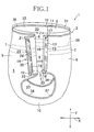
- Figs. 1 through 4 illustrate a first embodiment according to the present invention in the form of a diaper for adult as one example.
- a diaper 1 comprises a liquid-absorbent chassis 2 and fastening means 3.
- the chassis 2 has a longitudinal direction Y, a transverse direction X, a circumferential direction Z, an inner side 4 facing the wearer's skin and an outer side 5 facing the wearer's garment.
- the chassis 2 comprises an inner sheet 6 defining the inner side 4 facing the wearer's skin, an outer sheet 7 defining the outer side 5 facing the wearer' s garment and a liquid-absorbent core (not shown) interposed between these inner and outer sides 6, 7.
- the inner sheet 6 may be formed, for example, from a liquid-pervious nonwoven fabric
- the outer sheet 7 may be formed, for example, from a liquid-impervious film
- the liquid-absorbent core may be formed, for example, from a mixture of fluff pulp and super-absorbent polymer particles.
- materials for these components may be selected from those conventionally used in the relevant technical field.
- the chassis 2 configurationally comprises a front waist region 8, a rear waist region 209 and a crotch region 10 sandwiched between the front and rear waist regions 8, 9.
- the front waist region 8 includes a pair of side edges 11 opposed to each other in the transverse direction X and extending in the longitudinal direction Y and the rear waist region 9 includes a pair of side edges 12 opposed to each other in the transverse direction X and extending in the longitudinal direction Y.
- the outer sheet 7 is provided along the side edges 11 of the front waist region with first fastening members 13 comprising loop elements attached thereto by use of adhesive or welding technique.
- the inner sheet 6 is provided along the side edges 12 of the rear waist region with second fastening members 14 comprising hook elements adapted to be detachably engaged with the first fastening members 13 wherein these second fastening members 14 also may be attached thereto by use of adhesive or welding technique.
- the first fastening members 13 cooperate with the associated second fastening members 14 to provide fastening means 3 according to the second aspect of the present invention.
- the first and second fastening members 13, 14 have substantially the same dimensions as those of the side edges 21, 22 of the front and rear waist regions, respectively, as measured in the longitudinal direction.
- the first fastening member 13 includes inner and outer side edges 15, 16 opposed to each other in the transverse direction X and extending in the longitudinal direction Y and upper and lower ends 17, 18 opposed to each other in the longitudinal direction Y and extending in the transverse direction X.
- the second fastening member 14 includes inner and outer side edges 19, 20 opposed to each other in the transverse direction X and extending in the longitudinal direction Y and upper and lower ends 21, 22 opposed to each other in the longitudinal direction Y and extending in the transverse direction X.
- the inner side edges 15, 19 are placed aside from the outer side edges 16, 20 inwardly of the chassis 2 as viewed in the transverse direction X.
- Fig. 2 illustrates details of a second fastening member 14.
- the second fastening member 14 is formed with a folding guide means 23 facilitating the second fastening member 14 to be folded.
- the second fastening member 14 is a thermoplastic member formed from a polyolefin resin, particularly a mixture of polypropylene and polyethylene.
- the folding guide means 23 includes a foldable region 24 formed by heat processing the second fastening member 14.
- the foldable region 24 obtained by heat processing the second fastening member 14 having a thermal plasticity has a relatively high stiffness and a relatively thin thickness in comparison to the remaining region not subjected to heat processing. Such differential stiffness and thickness facilitate this foldable region 24 to be folded.
- the foldable region 24 comprises an upper fold line 25 placed aside toward the upper end 21 and a lower fold line 26 placed aside toward the lower end 22 so that the second fastening member 14 may be folded between the upper fold line 25 and the lower fold line 26.
- a dimension t measured from the upper fold line 25 to the lower fold line 26 is in a range of about 3 to 20 mm. If the dimension t is less than about 3 mm, the dimension t will be narrower than the thickness of the second fastening member 14 and it will be difficult to fold the second fastening member 14 smoothly. If the dimension t exceeds about 20 mm, on the contrary, a region free from engagement with the first fastening member 13 will become unacceptably large and, in consequence, the front and rear waist regions 8, 9 will be apt to be unfastened from each other.
- the upper and lower fold lines 25, 26 respectively extend from the outer side edge 20 to the inner side edge 19 and respectively include ends 25a, 26a lying on the outer side edge 20 and ends 25b, 26b lying on the inner side edge 19.
- the upper and lower fold lines 25, 26 extend substantially in parallel to each other and the ends 25a, 26a on the outer side edge 20 are placed aside from the ends 25b, 26b on the inner side edge 19 toward the upper end 21.
- the foldable region 24 obliquely extends with respect to the longitudinal center line P-P bisecting the second fastening member 14 in the transverse direction X. More specifically, the foldable region 24 extends at an angle ⁇ preferably of 30 to 60° and most preferably of about 45° with respect to extension of the line orthogonal to the longitudinal center line P-P.
- a dimension A of the second fastening member 14 as measured from the upper end 21 to the lower end 22 in the longitudinal direction Y is about 130 mm and a dimension B as measured from the upper end 21 to the end 25a lying on the outer side edge 20 is about 10 to 50 mm.
- a dimension C of the second fastening member 14 as measured from the inner side edge 19 to the outer side edge 20 is about 15 mm. It should be understood here that may be appropriately varied depending on the diaper's size these dimensions and the types of materials to be used.
- the second fastening member 14 is divided, about the foldable region 24 defining the boundary, in an upper region 27 lying on the side of the upper end 21 and a lower region 28 lying on the side of the lower end 22.
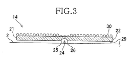
- Fig. 3 is a sectional view taken along the longitudinal center line P-P in Fig. 2 .
- the second fastening member 14 is heated at a temperature of about 120°C under a pressure from the side on which the second fastening member 14 has been bonded to the chassis 2. Being thermoplastic, the second fastening member 14 is locally fused so as to form a concave groove as it is heated under pressure. At the same time, a hook forming surface 30 of the second fastening member 14 is also pressurized and the hook elements are locally collapsed. An area of the second fastening member 14 locally heated and pressurized defines the foldable region 24.
- the foldable region 24 has a higher stiffness and a thinner thickness than the remaining region. In consequence, the second fastening member 14 can be easily folded along this foldable region 24.
- first and second fastening members 13, 14 may be engaged together to join the front waist region 8 with the rear waist region 9 and thereby to obtain the diaper 1 of pant-type as shown in Fig. 1 .
- a waist-opening 33 is defined by respective upper edges 31, 32 of the front and rear waist regions 8, 9, i.e., these edges cooperating with each other to define a peripheral edge of the waist-opening 33 and a pair of leg-openings 26 defined by transversely opposite side edges 34, 34 of the crotch region 10, i.e., the edges adapted to define peripheral edges of the respective leg-openings 35.
- the front and rear halves 31, 32 of the waist-opening' s peripheral edge are provided with waist elastic members 36 attached thereto under tension so as to extend along these halves of 31, 32 of the waist-opening's peripheral edge.
- the leg-openings' peripheral edges 34 are provided inside thereof with leg elastic members 37 attached thereto under tension so as to extend along these peripheral edges 34, respectively.
- Both the waist elastic members 36 and the leg elastic members 37 comprise a plurality of rubber strings so that s desired fit of the front and rear halves 31, 32 of the waist-opening's peripheral edge and of the respective leg-openings' peripheral edges 34 may be assured by a contractile force of these rubber strings.
- the front and rear waist regions 8, 9 are provided at substantially middle levels as viewed in the longitudinal direction Y with auxiliary elastic members 38 attached thereto under tension to improve fitness of the diaper to the wearer's body.
- the auxiliary elastic member 38 extends around the wearer's waist in a circumferential direction Z and comprises a plurality of rubber strings arranged to be spaced one from another in the longitudinal direction Y so that a contractile force of these rubber strings may ensure the front and rear waist regions to fit to the wearer's body at the respective middle levels of the front and rear waist regions 8, 9 thereof.
- the waist elastic member 36, the leg elastic member 37 and the auxiliary elastic member 38 natural rubber or synthetic rubber such as that made of polyurethane may be used and it is possible to implement these elastic members in the form of an elasticized fibrous nonwoven fabric or elasticized plastic sheet instead of the rubber strings.
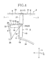
- the first fastening members 13 and the second fastening members 14 are engaged with each other in such a manner as will be described with reference to Fig. 4 .
- Each of the second fastening members 14 lying outside as viewed in the circumferential direction Z is put in engagement with the associated first fastening member 13 lying inside as viewed in the circumferential direction Z, i.e., lying on the side of the wearer' body.
- the second fastening member 14 may be previously folded along the foldable region 24.
- a differential stiffness as well as a differential thickness between the foldable region 24 and the remaining region facilitates the second fastening member 14 to be folded along this foldable region 24.
- the foldable region 24 obliquely extends downward from the outer side edge 20 to the inner side edge 19 and such feature also facilitates the lower region 28 to be folded outward in the circumferential direction Z.
- the lower region 28 can be folded outward easier than inward in the circumferential direction Z. Thereby it is possible to prevent the lower region 28 from unintentionally being engaged with the first fastening member 13 and furthermore to protect the wearer's skin from being injured by the hook elements on the lower region 28.
- the foldable region 24 extends at an angle ⁇ of about 30 to 60° with respect to the line Q-Q. If this angle ⁇ is set to be smaller than about 30°, it will be difficult to fold the lower region 28 neatly and eventually the lower region 28 will partially overlap the upper region 27. In addition to such inconvenience, the periphery 34 of the associated leg-opening will make it difficult to fold the lower region 28. If the angle a is set to be larger than about 60°, a dimension in the longitudinal direction Y over which the upper region 27 is engaged with the first fastening member 13 will be substantially elongated and consequently it will be difficult to put the upper region 27 in accurate engagement with the first fastening member 13.
- the lower region 28 With the lower region 28 folded in this manner, the upper end 21 of the second fastening member 14 is aligned with the upper end 17 of the first fastening member 13 and then the upper region 27 of the second fastening member 14 is engaged with the first fastening member 23.
- the lower region 28 in the step of put the upper region 27 in engagement with the second fastening member 14, the lower region 28 should not be unintentionally engaged with the first fastening member 13 because the lower region 28 has been folded outward.
- the lower region 28 may be unfolded to its initial position and then put in engagement with the first fastening member 13.
- the dimension B as measured from the upper end 21 to the end 25a lying on the outer side edge of the second fastening member 14 is set in a range of about 10 to 50 mm. If the dimension B is shorter than 10 mm, engaging force between the upper region 27 and the first fastening member 13 will be too weak to maintain the upper region 27 in engagement with the first fastening member 13 in the course of engaging the lower region 28 with the first fastening member 13. If the dimension B is longer than about 50 mm, on the contrary, it will become difficult to put the upper region 27 in accurate engagement with the first fastening member 13.
- Formation of the folding guide means 23 along each of the side edges 12 of the rear waist region is effective to improve a feeling to wear the diaper 1.
- the folding guide means 23 is more flexible in concert with movement of the wearer than the remaining part and deformable in conformity to the wearer' body. Without formation of the folding guide means 23, a stiffness of the first and second fastening members 13, 14 would deteriorate a feeling to wear.
- first and second fastening members 13, 14 are described herein wherein the former includes the loop elements and the latter includes the hook elements, it is also possible that the first fastening member 13 includes the hook elements and the second fastening member 14 including the loop elements.
- the hook elements usually have a stiffness higher than that of the loop elements. Taking account of this, it is preferred to press the hook elements having the higher stiffness against the loop elements and thereby to achieve a relatively confirm engagement.
- Fastening means 3 is not limited to such a combination of the first and second fastening members 13, 14 but the other means such as pressure-sensitive adhesive tape may be used so far as the front and rear waist regions 8, 9 can be detachably fastened together.
- first fastening members 13 While formation of the folding guide means 23 are limited to the second fastening members 14 according to this embodiment, it is possible to form the first fastening members 13 also with the folding guide means 23. If both of the first and second fastening members 13, 14 are formed with the folding guide means 23, operation of engagement will be further easier. While the first fastening member 13 is attached directly to the outer sheet 7 and the second fastening member 14 is attached directly to the inner sheet 6 according to this embodiment, it is also possible to prepare separate retaining sheets for these fastening members and to attach these retaining sheets to the inner sheet 6 or the outer sheet 7.
- the second fastening members 14 are attached to the side edges 12 of the rear waist region after the second fastening members 14 have been formed with the folding guide means 23 according to this embodiment, it is also possible to form the folding guide means 23 after the second fastening members 14 have been attached to the side edges 12 of the rear waist region.
- Fig. 5 illustrates a second embodiment according to the present invention wherein the inner side 4 of the diaper 1 faces the wearer's skin.
- This second embodiment is distinguished from the first embodiment with respect to the folding guide means 23 and the other components are similar to those in the first embodiment. The similar components will not be described repetitively.
- the folding guide means 23 are implemented in the form of slit distributed region 39 provided in the second fastening members 14 and the side edges 12 of the rear waist region in the chassis 2.
- the slit distributed region 39 comprises five slit rows 40 arranged substantially in parallel one to another wherein each row includes a plurality of slits arrange at regular intervals.
- the individual slit constituting each of the slit rows 40 has a length of about 3 mm and a distance between each pair of the adjacent slits is about 3 mm.
- the slit distributed region 39 is formed, for example, by feeding the side edges 12 of the rear waist region in the chassis 2 together with the second fastening members 14 attached to the respective side edges 12 to a gear mechanism provided with a cutter.
- the angle ⁇ of the foldable region 24 is defined by an angle included between the extension of the single slit row 40 and the line Q-Q.
- the slit distributed region 39 exhibits a reduced stiffness in comparison to the remaining region and correspondingly more flexible than the remaining region. Consequentially, the upper region 27 can be put in engagement with the first fastening member 13 after the lower region 28 has been folded outward and thereby the second fastening member 14 can be easily and reliably engaged with the first fastening member 13.
- the slit rows 40 are formed after the second fastening member 14 has been attached to the chassis 2 according to this embodiment, it is also possible to attach the second fastening members 14 to the chassis 2 after the second fastening members 14 have been formed with the slit rows 40. In this case, the slit rows 40 are formed only in the second fastening members 14 and the chassis 2 is formed with none of the slit rows 40.
- the dimension of the individual slit and the number of the slit rows 40 are not limited to this embodiment and may be appropriately selected.
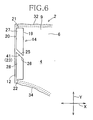
- Fig. 6 illustrates a third embodiment according to the present invention wherein the folding guide means 23 may be implemented in the form of a separator region 41 separating the upper region 27 and the lower region 28 of the second fastening member 14 from each other.
- the other components are similar to those in the first embodiment and will not be described repetitively.
- the second fastening member 14 is partially cut out to form the folding guide means 23.
- the upper fold line 25 is formed on the side of the upper region 27 and the lower fold line 26 is formed on the side of the lower region 28 about the separator region 41.
- Location of the folding guide means 23 is similar to the case of the first embodiment.
- the second fastening member 14 is not present in the separator region 41 defining the folding guide means 23, allowing a stiffness of the separator region 41 to be reduced in comparison to the remaining region. In consequence, the second fastening member 14 can be easily folded about the separator region 41.
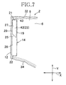
- Fig. 7 illustrates a fourth embodiment according to the present invention wherein the folding guide means 23 comprises a high stiffness member 42 provided in the upper region 27 of the second fastening member 14.
- the other components are similar to those in the first embodiment and will not be described repetitively.
- the high stiffness member 14 may be formed, for example, by a sheet member such as a nonwoven fabric, woven fabric or film and interposed between the second fastening member 14 and the inner sheet 6.
- the high stiffness member 42 has its upper end 43 substantially in conformity with the upper end 21 of the second fastening member 14 and its lower end serving as the upper fold line 25. It will be appreciated that the upper fold line 25 serves also as the lower fold line 26 which is not formed in this embodiment.
- the upper region 27 is defined by the second fastening member 14 and the high stiffness member 42 while the lower region 28 is defined by the second fastening member 14 alone.
- a differential stiffness between these upper and lower regions 27, 28 facilitates the second fastening member 14 to be folded about the upper fold line 25.
- the high stiffness member 42 is provided over the entire upper region 27 according to this embodiment, it is possible to provide the high stiffness member 42 only in the vicinity of the upper fold line 25. It is also possible to provide the high stiffness member 42 on the side of the lower region 28 so as to generate a differential stiffness between the lower region 28 and the upper region 27.
Description
- The present invention relates to wearing articles and particularly to wearing articles such as disposable diapers, toilet-training pants, incontinent briefs, or diaper covers and the like.
- Disposable diapers having front and rear waist regions detachably fastened together along transversely opposite side edges of diapers is known, for example, from the disclosure of
JP 2002-532147W JP 2002-532147W
PATENT DOCUMENT 1:JP 2002-532147W -
WO2007/122519 A1 -
JP10155834 A - According to the disclosure, the hook and loop elements extend in a longitudinal direction along the transversely opposite side edges of the front and rear waist regions, respectively. Lengths of the hook and loop elements are dimensioned to be substantially equal to lengths of the respective side edges to enlarge the area over which these elements are engaged one with another and thereby to enhance the fastening effect. Operation of engaging the hook and loop one with another is carried out, for example, as will be described. Such operation is started by engaging the longitudinally upper end of the hook element with associated upper end of the loop element for positioning followed by engaging the remaining portions of the respective elements with one another. However, the longitudinally lower portions of the respective elements should be unintentionally engaged with one another in the course of positioning the upper ends, resulting in a misaligned engagement. To remedy this, the unintentionally engaged portions must be disengaged from each other and it must be tried to engage again these portions with each other so as to assure the proper positioning, i.e., the proper alignment. In this regard, the fastening means adopted by the disposable diaper cited above has left unsolved a problem such that time and labor should be taken for handling of the fastening means. This problem has been significant particularly in the adult diaper of large size.
- In view of the problem as has been discussed above, the present invention provides a wearing article improved so that the front waist region and the rear waist region can be easily and normally engaged with each other.
- According to the present invention, there is provided an wearing article comprising a liquid-absorbent chassis having a longitudinal direction, a transverse direction, an inner side facing the wearer's skin, an outer side facing the wearer's garment, a front waist region, a rear waist region and a crotch region extending between the front and rear waist region, and fastening means adapted to detachably fasten the front and rear waist regions to each other along respective pairs of side edges thereof opposed in the transverse direction and extending in the longitudinal direction.
- In the present invention, the fastening means comprise first fastening members lying inside as viewed in a circumferential direction and second fastening members lying outside as viewed in the circumferential direction when joining the front and rear waist regions to each other, the first fastening members are attached to the side edges so as to extend in the longitudinal direction and respectively have inner and outer side edges opposed in the transverse direction, the second fastening members are attached to the side edges so as to extend in the longitudinal direction and respectively have inner and outer side edges opposed in the transverse direction in a manner that the second fastening members are detachably engaged with associated the first fastening members, and the second fastening members and the side edges to which the second fastening members are attached are provided with folding guide means serving to facilitate the second fastening members to be folded along foldable regions defined by the folding guide means.
- The present invention is characterised in that each of the foldable regions extends from the outer side edge to the inner side edge in a manner that, between said foldable region and a line orthogonal to a longitudinal center line bisecting of the second fastening member in said transverse direction, an angle of 30 to 60° is included.
- According to a preferred embodiment, the second fastening member includes upper and lower ends opposed to each other in the longitudinal direction and extending in the transverse direction, and the foldable region including an end lying on the outer side edge and an end lying on the inner side edge, wherein the end lying on the outer side edge is put aside toward the upper end relative to the end lying on the inner side edge so that the foldable region extends obliquely from the former end on the outer side edge to the latter end on the inner side edge.
- According to another preferred embodiment, the folding guide means is formed by heat processing.
- According to yet another preferred embodiment, the folding guide means comprises a slit distributed region.
- According to further another preferred embodiment, the folding guide means comprises a separator region defined by partially cutting out the second fastening member.
- According to an additional preferred embodiment, the folding guide means comprises a high stiffness member attached to the second fastening member.
- The folding guide means provided in the second fastening member ensures that the upper region of the second fastening member can be put in engagement with the first fastening member while the second fastening member is maintained in the folded state. After the upper region of the second fastening member has been engaged with the first fastening member, the lower region may be unfolded back and this lower region may be put in engagement with the first fastening member. In this way, the lower region of the second fastening member should not be unintentionally engaged with the first fastening member in the course of engaging the upper region of the second fastening member with the first fastening member.
- The foldable region extends at an angle α of 30 to 60° with respect to the line orthogonal to the longitudinal center line of the second fastening member and the second fastening member may be folded along this foldable region. In this way, the second fastening member can be smoothly folded and can be well maintained in the folded position.
- The end of the foldable region lying on the outer side edge is aside upward from the end lying on the inner side edge, resulting in that the foldable region obliquely extends downward from the outer side edge to the inner side edge. In this way, the second fastening member with its lower region folded outward can be smoothly put in engagement with the first fastening member.
-
- [
FIG. 1] Fig. 1 is a perspective view showing a first embodiment of a diaper according to the present invention. - [
FIG. 2] Fig. 2 is a diagram illustrating details of the second fastening element. - [
FIG. 3] Fig. 3 is a sectional view taken along a longitudinal center line P-P inFig. 2 . - [
FIG. 4] Fig. 4 is a diagram illustrating front and rear waist regions as engaged one with another. - [
FIG. 5] Fig. 5 is a diagram partially illustrating a second embodiment according to the present invention. - [
FIG. 6] Fig. 6 is a diagram partially illustrating a third embodiment according to the invention. - [
FIG. 7] Fig. 7 is a diagram partially illustrating a fourth embodiment according to the present invention. -
- 1
- diaper
- 2
- liquid-absorbent chassis
- 3
- fastening means
- 4
- inner side facing the wearer's skin
- 5
- outer side facing the wearer's garment
- 8
- front waist region
- 9
- rear waist region
- 10
- crotch region
- 11
- transversely opposite side edges of front waist region
- 12
- transversely opposite side edges of rear waist region
- 13
- first fastening member
- 14
- second fastening member
- 15
- inner side edge
- 16
- outer side edge
- 19
- inner side edge
- 20
- outer side edge
- 21
- upper end
- 22
- lower end
- 23
- folding guide means
- 24
- foldable region
- 25a
- end
- 25b
- end
- 39
- slit distributed region
- 41
- separator region
- 42
- high stiffness member
- X
- transverse direction
- Y
- longitudinal direction
- Z
- circumferential direction
-
Figs. 1 through 4 illustrate a first embodiment according to the present invention in the form of a diaper for adult as one example. As seen inFig. 1 , a diaper 1 comprises a liquid-absorbent chassis 2 and fastening means 3. Thechassis 2 has a longitudinal direction Y, a transverse direction X, a circumferential direction Z, aninner side 4 facing the wearer's skin and anouter side 5 facing the wearer's garment. Thechassis 2 comprises aninner sheet 6 defining theinner side 4 facing the wearer's skin, anouter sheet 7 defining theouter side 5 facing the wearer' s garment and a liquid-absorbent core (not shown) interposed between these inner andouter sides inner sheet 6 may be formed, for example, from a liquid-pervious nonwoven fabric, theouter sheet 7 may be formed, for example, from a liquid-impervious film and the liquid-absorbent core may be formed, for example, from a mixture of fluff pulp and super-absorbent polymer particles. Generally, materials for these components may be selected from those conventionally used in the relevant technical field. Thechassis 2 configurationally comprises afront waist region 8, a rear waist region 209 and acrotch region 10 sandwiched between the front andrear waist regions - The
front waist region 8 includes a pair of side edges 11 opposed to each other in the transverse direction X and extending in the longitudinal direction Y and therear waist region 9 includes a pair of side edges 12 opposed to each other in the transverse direction X and extending in the longitudinal direction Y. Theouter sheet 7 is provided along the side edges 11 of the front waist region withfirst fastening members 13 comprising loop elements attached thereto by use of adhesive or welding technique. - The
inner sheet 6 is provided along the side edges 12 of the rear waist region withsecond fastening members 14 comprising hook elements adapted to be detachably engaged with thefirst fastening members 13 wherein thesesecond fastening members 14 also may be attached thereto by use of adhesive or welding technique. Thefirst fastening members 13 cooperate with the associatedsecond fastening members 14 to provide fastening means 3 according to the second aspect of the present invention. - The first and
second fastening members first fastening member 13 includes inner and outer side edges 15, 16 opposed to each other in the transverse direction X and extending in the longitudinal direction Y and upper and lower ends 17, 18 opposed to each other in the longitudinal direction Y and extending in the transverse direction X. Thesecond fastening member 14 includes inner and outer side edges 19, 20 opposed to each other in the transverse direction X and extending in the longitudinal direction Y and upper and lower ends 21, 22 opposed to each other in the longitudinal direction Y and extending in the transverse direction X. The inner side edges 15, 19 are placed aside from the outer side edges 16, 20 inwardly of thechassis 2 as viewed in the transverse direction X. -
Fig. 2 illustrates details of asecond fastening member 14. As illustrated, thesecond fastening member 14 is formed with a folding guide means 23 facilitating thesecond fastening member 14 to be folded. Thesecond fastening member 14 is a thermoplastic member formed from a polyolefin resin, particularly a mixture of polypropylene and polyethylene. The folding guide means 23 includes afoldable region 24 formed by heat processing thesecond fastening member 14. Thefoldable region 24 obtained by heat processing thesecond fastening member 14 having a thermal plasticity has a relatively high stiffness and a relatively thin thickness in comparison to the remaining region not subjected to heat processing. Such differential stiffness and thickness facilitate thisfoldable region 24 to be folded. - The
foldable region 24 comprises anupper fold line 25 placed aside toward theupper end 21 and alower fold line 26 placed aside toward thelower end 22 so that thesecond fastening member 14 may be folded between theupper fold line 25 and thelower fold line 26. A dimension t measured from theupper fold line 25 to thelower fold line 26 is in a range of about 3 to 20 mm. If the dimension t is less than about 3 mm, the dimension t will be narrower than the thickness of thesecond fastening member 14 and it will be difficult to fold thesecond fastening member 14 smoothly. If the dimension t exceeds about 20 mm, on the contrary, a region free from engagement with thefirst fastening member 13 will become unacceptably large and, in consequence, the front andrear waist regions - The upper and
lower fold lines outer side edge 20 to theinner side edge 19 and respectively include ends 25a, 26a lying on theouter side edge 20 and ends 25b, 26b lying on theinner side edge 19. The upper andlower fold lines ends outer side edge 20 are placed aside from theends inner side edge 19 toward theupper end 21. Specifically, thefoldable region 24 obliquely extends with respect to the longitudinal center line P-P bisecting thesecond fastening member 14 in the transverse direction X. More specifically, thefoldable region 24 extends at an angle α preferably of 30 to 60° and most preferably of about 45° with respect to extension of the line orthogonal to the longitudinal center line P-P. - A dimension A of the
second fastening member 14 as measured from theupper end 21 to thelower end 22 in the longitudinal direction Y is about 130 mm and a dimension B as measured from theupper end 21 to theend 25a lying on theouter side edge 20 is about 10 to 50 mm. A dimension C of thesecond fastening member 14 as measured from theinner side edge 19 to theouter side edge 20 is about 15 mm. It should be understood here that may be appropriately varied depending on the diaper's size these dimensions and the types of materials to be used. Thesecond fastening member 14 is divided, about thefoldable region 24 defining the boundary, in anupper region 27 lying on the side of theupper end 21 and alower region 28 lying on the side of thelower end 22. -
Fig. 3 is a sectional view taken along the longitudinal center line P-P inFig. 2 . Thesecond fastening member 14 is heated at a temperature of about 120°C under a pressure from the side on which thesecond fastening member 14 has been bonded to thechassis 2. Being thermoplastic, thesecond fastening member 14 is locally fused so as to form a concave groove as it is heated under pressure. At the same time, ahook forming surface 30 of thesecond fastening member 14 is also pressurized and the hook elements are locally collapsed. An area of thesecond fastening member 14 locally heated and pressurized defines thefoldable region 24. Thefoldable region 24 has a higher stiffness and a thinner thickness than the remaining region. In consequence, thesecond fastening member 14 can be easily folded along thisfoldable region 24. - These first and
second fastening members front waist region 8 with therear waist region 9 and thereby to obtain the diaper 1 of pant-type as shown inFig. 1 . In the diaper 1 of pant-type, a waist-opening 33 is defined by respectiveupper edges rear waist regions openings 26 defined by transversely opposite side edges 34, 34 of thecrotch region 10, i.e., the edges adapted to define peripheral edges of the respective leg-openings 35. The front andrear halves elastic members 36 attached thereto under tension so as to extend along these halves of 31, 32 of the waist-opening's peripheral edge. The leg-openings'peripheral edges 34 are provided inside thereof with legelastic members 37 attached thereto under tension so as to extend along theseperipheral edges 34, respectively. Both the waistelastic members 36 and the legelastic members 37 comprise a plurality of rubber strings so that s desired fit of the front andrear halves peripheral edges 34 may be assured by a contractile force of these rubber strings. - The front and
rear waist regions elastic members 38 attached thereto under tension to improve fitness of the diaper to the wearer's body. The auxiliaryelastic member 38 extends around the wearer's waist in a circumferential direction Z and comprises a plurality of rubber strings arranged to be spaced one from another in the longitudinal direction Y so that a contractile force of these rubber strings may ensure the front and rear waist regions to fit to the wearer's body at the respective middle levels of the front andrear waist regions - For the waist
elastic member 36, the legelastic member 37 and the auxiliaryelastic member 38, natural rubber or synthetic rubber such as that made of polyurethane may be used and it is possible to implement these elastic members in the form of an elasticized fibrous nonwoven fabric or elasticized plastic sheet instead of the rubber strings. - In the diaper 1, the
first fastening members 13 and thesecond fastening members 14 are engaged with each other in such a manner as will be described with reference toFig. 4 . Each of thesecond fastening members 14 lying outside as viewed in the circumferential direction Z is put in engagement with the associated first fasteningmember 13 lying inside as viewed in the circumferential direction Z, i.e., lying on the side of the wearer' body. For operation of such engagement, thesecond fastening member 14 may be previously folded along thefoldable region 24. A differential stiffness as well as a differential thickness between thefoldable region 24 and the remaining region facilitates thesecond fastening member 14 to be folded along thisfoldable region 24. Thefoldable region 24 obliquely extends downward from theouter side edge 20 to theinner side edge 19 and such feature also facilitates thelower region 28 to be folded outward in the circumferential direction Z. Thelower region 28 can be folded outward easier than inward in the circumferential direction Z. Thereby it is possible to prevent thelower region 28 from unintentionally being engaged with thefirst fastening member 13 and furthermore to protect the wearer's skin from being injured by the hook elements on thelower region 28. - As has previously been described, the
foldable region 24 extends at an angle α of about 30 to 60° with respect to the line Q-Q. If this angle α is set to be smaller than about 30°, it will be difficult to fold thelower region 28 neatly and eventually thelower region 28 will partially overlap theupper region 27. In addition to such inconvenience, theperiphery 34 of the associated leg-opening will make it difficult to fold thelower region 28. If the angle a is set to be larger than about 60°, a dimension in the longitudinal direction Y over which theupper region 27 is engaged with thefirst fastening member 13 will be substantially elongated and consequently it will be difficult to put theupper region 27 in accurate engagement with thefirst fastening member 13. - With the
lower region 28 folded in this manner, theupper end 21 of thesecond fastening member 14 is aligned with theupper end 17 of thefirst fastening member 13 and then theupper region 27 of thesecond fastening member 14 is engaged with thefirst fastening member 23. Referring toFig. 4 , in the step of put theupper region 27 in engagement with thesecond fastening member 14, thelower region 28 should not be unintentionally engaged with thefirst fastening member 13 because thelower region 28 has been folded outward. Once theupper region 27 has been firmly engaged with thefirst fastening member 13, thelower region 28 may be unfolded to its initial position and then put in engagement with thefirst fastening member 13. In this step, it is ensured that thelower region 28 is reliably engaged with thefirst fastening member 13 at the desired position without any undesirable displacement because theupper region 27 has already been firmly engaged with thefirst fastening member 13. In this way, the presence of the folding guide means 23 assures that thesecond fastening member 14 can be easily and reliably engaged with thefirst fastening member 13. - As has previously been described, the dimension B as measured from the
upper end 21 to theend 25a lying on the outer side edge of thesecond fastening member 14 is set in a range of about 10 to 50 mm. If the dimension B is shorter than 10 mm, engaging force between theupper region 27 and thefirst fastening member 13 will be too weak to maintain theupper region 27 in engagement with thefirst fastening member 13 in the course of engaging thelower region 28 with thefirst fastening member 13. If the dimension B is longer than about 50 mm, on the contrary, it will become difficult to put theupper region 27 in accurate engagement with thefirst fastening member 13. - Formation of the folding guide means 23 along each of the side edges 12 of the rear waist region is effective to improve a feeling to wear the diaper 1. With the diaper 1 put on the wearer's body also, the folding guide means 23 is more flexible in concert with movement of the wearer than the remaining part and deformable in conformity to the wearer' body. Without formation of the folding guide means 23, a stiffness of the first and
second fastening members - While the first and
second fastening members first fastening member 13 includes the hook elements and thesecond fastening member 14 including the loop elements. However, it should be noted here that the hook elements usually have a stiffness higher than that of the loop elements. Taking account of this, it is preferred to press the hook elements having the higher stiffness against the loop elements and thereby to achieve a relatively confirm engagement. Fastening means 3 is not limited to such a combination of the first andsecond fastening members rear waist regions - While formation of the folding guide means 23 are limited to the
second fastening members 14 according to this embodiment, it is possible to form thefirst fastening members 13 also with the folding guide means 23. If both of the first andsecond fastening members first fastening member 13 is attached directly to theouter sheet 7 and thesecond fastening member 14 is attached directly to theinner sheet 6 according to this embodiment, it is also possible to prepare separate retaining sheets for these fastening members and to attach these retaining sheets to theinner sheet 6 or theouter sheet 7. - While the
second fastening members 14 are attached to the side edges 12 of the rear waist region after thesecond fastening members 14 have been formed with the folding guide means 23 according to this embodiment, it is also possible to form the folding guide means 23 after thesecond fastening members 14 have been attached to the side edges 12 of the rear waist region. -
Fig. 5 illustrates a second embodiment according to the present invention wherein theinner side 4 of the diaper 1 faces the wearer's skin. This second embodiment is distinguished from the first embodiment with respect to the folding guide means 23 and the other components are similar to those in the first embodiment. The similar components will not be described repetitively. - According to this embodiment, the folding guide means 23 are implemented in the form of slit distributed
region 39 provided in thesecond fastening members 14 and the side edges 12 of the rear waist region in thechassis 2. - The slit distributed
region 39 comprises five slitrows 40 arranged substantially in parallel one to another wherein each row includes a plurality of slits arrange at regular intervals. The individual slit constituting each of theslit rows 40 has a length of about 3 mm and a distance between each pair of the adjacent slits is about 3 mm. The slit distributedregion 39 is formed, for example, by feeding the side edges 12 of the rear waist region in thechassis 2 together with thesecond fastening members 14 attached to the respective side edges 12 to a gear mechanism provided with a cutter. - Location of the folding guide means 23 in the form of the slit distributed
region 39 is the same as in the first embodiment. The angle α of thefoldable region 24 is defined by an angle included between the extension of thesingle slit row 40 and the line Q-Q. - The slit distributed
region 39 exhibits a reduced stiffness in comparison to the remaining region and correspondingly more flexible than the remaining region. Consequentially, theupper region 27 can be put in engagement with thefirst fastening member 13 after thelower region 28 has been folded outward and thereby thesecond fastening member 14 can be easily and reliably engaged with thefirst fastening member 13. - While the
slit rows 40 are formed after thesecond fastening member 14 has been attached to thechassis 2 according to this embodiment, it is also possible to attach thesecond fastening members 14 to thechassis 2 after thesecond fastening members 14 have been formed with theslit rows 40. In this case, theslit rows 40 are formed only in thesecond fastening members 14 and thechassis 2 is formed with none of theslit rows 40. - The dimension of the individual slit and the number of the
slit rows 40 are not limited to this embodiment and may be appropriately selected. -
Fig. 6 illustrates a third embodiment according to the present invention wherein the folding guide means 23 may be implemented in the form of aseparator region 41 separating theupper region 27 and thelower region 28 of thesecond fastening member 14 from each other. The other components are similar to those in the first embodiment and will not be described repetitively. - In the
separator region 41, thesecond fastening member 14 is partially cut out to form the folding guide means 23. In thesecond fastening member 14, theupper fold line 25 is formed on the side of theupper region 27 and thelower fold line 26 is formed on the side of thelower region 28 about theseparator region 41. Location of the folding guide means 23 is similar to the case of the first embodiment. - According to this embodiment, the
second fastening member 14 is not present in theseparator region 41 defining the folding guide means 23, allowing a stiffness of theseparator region 41 to be reduced in comparison to the remaining region. In consequence, thesecond fastening member 14 can be easily folded about theseparator region 41. -
Fig. 7 illustrates a fourth embodiment according to the present invention wherein the folding guide means 23 comprises ahigh stiffness member 42 provided in theupper region 27 of thesecond fastening member 14. The other components are similar to those in the first embodiment and will not be described repetitively. - The
high stiffness member 14 may be formed, for example, by a sheet member such as a nonwoven fabric, woven fabric or film and interposed between thesecond fastening member 14 and theinner sheet 6. - The
high stiffness member 42 has itsupper end 43 substantially in conformity with theupper end 21 of thesecond fastening member 14 and its lower end serving as theupper fold line 25. It will be appreciated that theupper fold line 25 serves also as thelower fold line 26 which is not formed in this embodiment. - According to this embodiment, the
upper region 27 is defined by thesecond fastening member 14 and thehigh stiffness member 42 while thelower region 28 is defined by thesecond fastening member 14 alone. With such a unique arrangement, a differential stiffness between these upper andlower regions second fastening member 14 to be folded about theupper fold line 25. - While the
high stiffness member 42 is provided over the entireupper region 27 according to this embodiment, it is possible to provide thehigh stiffness member 42 only in the vicinity of theupper fold line 25. It is also possible to provide thehigh stiffness member 42 on the side of thelower region 28 so as to generate a differential stiffness between thelower region 28 and theupper region 27.
Claims (6)
- A wearing article (1) comprising a liquid-absorbent chassis (2) having a longitudinal direction (Y), a transverse direction (X), an inner side (4) facing the wearer's skin, an outer side (5) facing the wearer's garment, a front waist region (8), a rear waist region (9) and a crotch region (10) extending between the front and rear waist regions (8, 9), and fastening means (13, 14) adapted to detachably fasten said front and rear waist regions (8, 9) to each other along respective pairs of side edges (11, 12) thereof opposed in said transverse direction (X) and extending in said longitudinal direction (Y), wherein:said fastening means (13, 14) comprise first fastening members (13) lying inside as viewed in a circumferential direction (Z) and second fastening members (14) lying outside as viewed in said circumferential direction (Z) when joining said front and rear waist regions (8, 9) to each other,said first fastening members (13) are attached to said side edges (11) so as to extend in said longitudinal direction (Y) and respectively have inner and outer side edges (15, 16) opposed in said transverse direction (X),said second fastening members (14) are attached to said side edges (12) so as to extend in said longitudinal direction (Y) and respectively have inner and outer side edges (19, 20) opposed in said transverse direction (X) in a manner that said second fastening members (14) are detachably engaged with associated said first fastening members (13), andsaid second fastening members (14) and said side edges (12) to which said second fastening members (14) are attached are provided with folding guide means(23) serving to facilitate said second fastening members (14) to be folded along foldable regions (24) defined by said folding guide means (23);characterised in that each of said foldable regions (24) extends from said outer side edge (20) to said inner side edge (19) in a manner that, between said foldable region (24) and a line orthogonal to a longitudinal center line bisecting of said second fastening member (14) in said transverse direction (X), an angle of 30 to 60° is included.
- The wearing article according to Claim 1, wherein said second fastening member (14) includes upper and lower ends (21, 22) opposed to each other in the longitudinal direction (Y) and extending in the transverse direction (X), and said foldable region (24) including an end lying on said outer side edge (20) and an end lying on said inner side edge (19), wherein said end lying on said outer side edge (20) is put aside toward said upper end (21) relative to said end lying on said inner side edge (19) so that said foldable region (24) extends obliquely from said former end on said outer side edge (20) to said latter end on said inner side edge (19).
- The wearing article according to Claim 1 or 2, wherein said folding guide means (23) is formed by heat processing.
- The wearing article according to Claim 1 or 2, wherein said folding guide means (23) comprises a slit distributed region (39).
- The wearing article according to Claim 1 or 2, wherein said folding guide means (23) comprises a separator region (41) defined by partially cutting out said second fastening member (14).
- The wearing article according to Claim 1 or 2, wherein said folding guide means (23) comprises a high stiffness member (42) attached to said second fastening member (14).
Applications Claiming Priority (2)
| Application Number | Priority Date | Filing Date | Title |
|---|---|---|---|
| JP2007304954A JP5211375B2 (en) | 2007-11-26 | 2007-11-26 | Wearing article |
| PCT/JP2008/064630 WO2009069342A1 (en) | 2007-11-26 | 2008-08-15 | Wear article |
Publications (3)
| Publication Number | Publication Date |
|---|---|
| EP2221032A1 EP2221032A1 (en) | 2010-08-25 |
| EP2221032A4 EP2221032A4 (en) | 2012-10-31 |
| EP2221032B1 true EP2221032B1 (en) | 2014-01-08 |
Family
ID=40678250
Family Applications (1)
| Application Number | Title | Priority Date | Filing Date |
|---|---|---|---|
| EP08853774.1A Not-in-force EP2221032B1 (en) | 2007-11-26 | 2008-08-15 | Wearing article |
Country Status (12)
| Country | Link |
|---|---|
| US (1) | US8684989B2 (en) |
| EP (1) | EP2221032B1 (en) |
| JP (1) | JP5211375B2 (en) |
| KR (1) | KR20100106983A (en) |
| CN (1) | CN101909566B (en) |
| AU (1) | AU2008330939A1 (en) |
| CA (1) | CA2706606A1 (en) |
| EA (1) | EA017482B1 (en) |
| MX (1) | MX2010005745A (en) |
| MY (1) | MY150512A (en) |
| UA (1) | UA102237C2 (en) |
| WO (1) | WO2009069342A1 (en) |
Families Citing this family (1)
| Publication number | Priority date | Publication date | Assignee | Title |
|---|---|---|---|---|
| JP2010065653A (en) * | 2008-09-12 | 2010-03-25 | Ito Racing Service Co Ltd | Mixer for fuel supply device |
Family Cites Families (11)
| Publication number | Priority date | Publication date | Assignee | Title |
|---|---|---|---|---|
| US5269776A (en) * | 1989-03-24 | 1993-12-14 | Paragon Trade Brands, Inc. | Disposable diaper with refastenable mechanical fastening system |
| JPH0565321A (en) | 1991-09-05 | 1993-03-19 | Asahi Chem Ind Co Ltd | Propylene/ethylene block copolymer |
| JP2536230Y2 (en) * | 1992-02-21 | 1997-05-21 | ユニ・チャーム株式会社 | Disposable diapers |
| JP3313293B2 (en) * | 1996-12-05 | 2002-08-12 | ユニ・チャーム株式会社 | Disposable diapers |
| KR100676797B1 (en) | 1998-12-18 | 2007-02-01 | 킴벌리-클라크 월드와이드, 인크. | Absorbent Article with Non-irritating Refastenable Seams |
| US6454751B1 (en) * | 1999-11-22 | 2002-09-24 | Kimberly-Clark Worldwide, Inc. | Absorbent articles having hinged fasteners |
| WO2000035397A1 (en) * | 1998-12-18 | 2000-06-22 | Kimberly-Clark Worldwide, Inc. | Absorbent articles having hinged fasteners |
| JP4792182B2 (en) * | 2001-09-04 | 2011-10-12 | 白十字株式会社 | Disposable absorbent article |
| US7198621B2 (en) * | 2002-12-19 | 2007-04-03 | Kimberly-Clark Worldwide, Inc. | Attachment assembly for absorbent article |
| JP4652724B2 (en) * | 2003-08-19 | 2011-03-16 | ユニ・チャーム株式会社 | Disposable absorbent article and method for producing the same |
| US7828784B2 (en) * | 2006-04-24 | 2010-11-09 | Kimberly-Clark Worldwide, Inc. | Absorbent articles with refastenable side seams and intuitive disposal feature |
-
2007
- 2007-11-26 JP JP2007304954A patent/JP5211375B2/en not_active Expired - Fee Related
-
2008
- 2008-08-15 MX MX2010005745A patent/MX2010005745A/en unknown
- 2008-08-15 CA CA2706606A patent/CA2706606A1/en not_active Abandoned
- 2008-08-15 WO PCT/JP2008/064630 patent/WO2009069342A1/en active Application Filing
- 2008-08-15 KR KR1020107013704A patent/KR20100106983A/en active IP Right Grant
- 2008-08-15 CN CN2008801241760A patent/CN101909566B/en not_active Expired - Fee Related
- 2008-08-15 EA EA201070621A patent/EA017482B1/en not_active IP Right Cessation
- 2008-08-15 US US12/744,779 patent/US8684989B2/en not_active Expired - Fee Related
- 2008-08-15 MY MYPI20102447 patent/MY150512A/en unknown
- 2008-08-15 UA UAA201007677A patent/UA102237C2/en unknown
- 2008-08-15 AU AU2008330939A patent/AU2008330939A1/en not_active Abandoned
- 2008-08-15 EP EP08853774.1A patent/EP2221032B1/en not_active Not-in-force
Also Published As
| Publication number | Publication date |
|---|---|
| WO2009069342A1 (en) | 2009-06-04 |
| JP2009125393A (en) | 2009-06-11 |
| AU2008330939A1 (en) | 2009-06-04 |
| UA102237C2 (en) | 2013-06-25 |
| MX2010005745A (en) | 2010-08-06 |
| MY150512A (en) | 2014-01-30 |
| US20110022021A1 (en) | 2011-01-27 |
| CN101909566A (en) | 2010-12-08 |
| EP2221032A1 (en) | 2010-08-25 |
| JP5211375B2 (en) | 2013-06-12 |
| EA201070621A1 (en) | 2011-02-28 |
| US8684989B2 (en) | 2014-04-01 |
| EP2221032A4 (en) | 2012-10-31 |
| CA2706606A1 (en) | 2009-06-04 |
| KR20100106983A (en) | 2010-10-04 |
| CN101909566B (en) | 2013-01-23 |
| EA017482B1 (en) | 2012-12-28 |
Similar Documents
| Publication | Publication Date | Title |
|---|---|---|
| US8777918B2 (en) | Disposable absorbent wearing article | |
| EP2481384B1 (en) | Disposable diaper | |
| EP1179331B1 (en) | Disposable undergarment | |
| AU2015235782A1 (en) | Absorbent article | |
| WO2007144838A1 (en) | Disposable pull-on garment | |
| EP2301500B1 (en) | Method of making wearing article | |
| EP1800639B1 (en) | Disposable wearing article | |
| AU2007342937B2 (en) | Method for making disposable pants-type diaper | |
| KR101560996B1 (en) | Disposable diaper | |
| EP2221032B1 (en) | Wearing article | |
| EP2286778A1 (en) | Pants-shaped wearing article | |
| EP2106771B1 (en) | Method for making disposable pants-type diaper | |
| AU2008315172B2 (en) | Wear article | |
| WO2013094673A1 (en) | Absorbent article |
Legal Events
| Date | Code | Title | Description |
|---|---|---|---|
| PUAI | Public reference made under article 153(3) epc to a published international application that has entered the european phase |
Free format text: ORIGINAL CODE: 0009012 |
|
| 17P | Request for examination filed |
Effective date: 20100618 |
|
| AK | Designated contracting states |
Kind code of ref document: A1 Designated state(s): AT BE BG CH CY CZ DE DK EE ES FI FR GB GR HR HU IE IS IT LI LT LU LV MC MT NL NO PL PT RO SE SI SK TR |
|
| AX | Request for extension of the european patent |
Extension state: AL BA MK RS |
|
| DAX | Request for extension of the european patent (deleted) | ||
| A4 | Supplementary search report drawn up and despatched |
Effective date: 20120927 |
|
| RIC1 | Information provided on ipc code assigned before grant |
Ipc: A61F 13/496 20060101ALI20120921BHEP Ipc: A61F 13/56 20060101ALI20120921BHEP Ipc: A61F 13/49 20060101AFI20120921BHEP |
|
| GRAP | Despatch of communication of intention to grant a patent |
Free format text: ORIGINAL CODE: EPIDOSNIGR1 |
|
| INTG | Intention to grant announced |
Effective date: 20130802 |
|
| GRAS | Grant fee paid |
Free format text: ORIGINAL CODE: EPIDOSNIGR3 |
|
| GRAA | (expected) grant |
Free format text: ORIGINAL CODE: 0009210 |
|
| AK | Designated contracting states |
Kind code of ref document: B1 Designated state(s): AT BE BG CH CY CZ DE DK EE ES FI FR GB GR HR HU IE IS IT LI LT LU LV MC MT NL NO PL PT RO SE SI SK TR |
|
| REG | Reference to a national code |
Ref country code: GB Ref legal event code: FG4D |
|
| REG | Reference to a national code |
Ref country code: CH Ref legal event code: EP |
|
| REG | Reference to a national code |
Ref country code: IE Ref legal event code: FG4D |
|
| REG | Reference to a national code |
Ref country code: AT Ref legal event code: REF Ref document number: 648198 Country of ref document: AT Kind code of ref document: T Effective date: 20140215 |
|
| REG | Reference to a national code |
Ref country code: DE Ref legal event code: R096 Ref document number: 602008029850 Country of ref document: DE Effective date: 20140220 |
|
| REG | Reference to a national code |
Ref country code: AT Ref legal event code: MK05 Ref document number: 648198 Country of ref document: AT Kind code of ref document: T Effective date: 20140108 |
|
| REG | Reference to a national code |
Ref country code: NL Ref legal event code: VDEP Effective date: 20140108 |
|
| REG | Reference to a national code |
Ref country code: LT Ref legal event code: MG4D |
|
| PG25 | Lapsed in a contracting state [announced via postgrant information from national office to epo] |
Ref country code: LT Free format text: LAPSE BECAUSE OF FAILURE TO SUBMIT A TRANSLATION OF THE DESCRIPTION OR TO PAY THE FEE WITHIN THE PRESCRIBED TIME-LIMIT Effective date: 20140108 Ref country code: IS Free format text: LAPSE BECAUSE OF FAILURE TO SUBMIT A TRANSLATION OF THE DESCRIPTION OR TO PAY THE FEE WITHIN THE PRESCRIBED TIME-LIMIT Effective date: 20140508 Ref country code: NO Free format text: LAPSE BECAUSE OF FAILURE TO SUBMIT A TRANSLATION OF THE DESCRIPTION OR TO PAY THE FEE WITHIN THE PRESCRIBED TIME-LIMIT Effective date: 20140408 |
|
| PG25 | Lapsed in a contracting state [announced via postgrant information from national office to epo] |
Ref country code: SE Free format text: LAPSE BECAUSE OF FAILURE TO SUBMIT A TRANSLATION OF THE DESCRIPTION OR TO PAY THE FEE WITHIN THE PRESCRIBED TIME-LIMIT Effective date: 20140108 Ref country code: PT Free format text: LAPSE BECAUSE OF FAILURE TO SUBMIT A TRANSLATION OF THE DESCRIPTION OR TO PAY THE FEE WITHIN THE PRESCRIBED TIME-LIMIT Effective date: 20140508 Ref country code: AT Free format text: LAPSE BECAUSE OF FAILURE TO SUBMIT A TRANSLATION OF THE DESCRIPTION OR TO PAY THE FEE WITHIN THE PRESCRIBED TIME-LIMIT Effective date: 20140108 Ref country code: FI Free format text: LAPSE BECAUSE OF FAILURE TO SUBMIT A TRANSLATION OF THE DESCRIPTION OR TO PAY THE FEE WITHIN THE PRESCRIBED TIME-LIMIT Effective date: 20140108 Ref country code: ES Free format text: LAPSE BECAUSE OF FAILURE TO SUBMIT A TRANSLATION OF THE DESCRIPTION OR TO PAY THE FEE WITHIN THE PRESCRIBED TIME-LIMIT Effective date: 20140108 Ref country code: NL Free format text: LAPSE BECAUSE OF FAILURE TO SUBMIT A TRANSLATION OF THE DESCRIPTION OR TO PAY THE FEE WITHIN THE PRESCRIBED TIME-LIMIT Effective date: 20140108 Ref country code: CY Free format text: LAPSE BECAUSE OF FAILURE TO SUBMIT A TRANSLATION OF THE DESCRIPTION OR TO PAY THE FEE WITHIN THE PRESCRIBED TIME-LIMIT Effective date: 20140108 |
|
| PG25 | Lapsed in a contracting state [announced via postgrant information from national office to epo] |
Ref country code: BE Free format text: LAPSE BECAUSE OF FAILURE TO SUBMIT A TRANSLATION OF THE DESCRIPTION OR TO PAY THE FEE WITHIN THE PRESCRIBED TIME-LIMIT Effective date: 20140108 Ref country code: LV Free format text: LAPSE BECAUSE OF FAILURE TO SUBMIT A TRANSLATION OF THE DESCRIPTION OR TO PAY THE FEE WITHIN THE PRESCRIBED TIME-LIMIT Effective date: 20140108 Ref country code: HR Free format text: LAPSE BECAUSE OF FAILURE TO SUBMIT A TRANSLATION OF THE DESCRIPTION OR TO PAY THE FEE WITHIN THE PRESCRIBED TIME-LIMIT Effective date: 20140108 |
|
| REG | Reference to a national code |
Ref country code: DE Ref legal event code: R097 Ref document number: 602008029850 Country of ref document: DE |
|
| PG25 | Lapsed in a contracting state [announced via postgrant information from national office to epo] |
Ref country code: EE Free format text: LAPSE BECAUSE OF FAILURE TO SUBMIT A TRANSLATION OF THE DESCRIPTION OR TO PAY THE FEE WITHIN THE PRESCRIBED TIME-LIMIT Effective date: 20140108 Ref country code: DK Free format text: LAPSE BECAUSE OF FAILURE TO SUBMIT A TRANSLATION OF THE DESCRIPTION OR TO PAY THE FEE WITHIN THE PRESCRIBED TIME-LIMIT Effective date: 20140108 Ref country code: RO Free format text: LAPSE BECAUSE OF FAILURE TO SUBMIT A TRANSLATION OF THE DESCRIPTION OR TO PAY THE FEE WITHIN THE PRESCRIBED TIME-LIMIT Effective date: 20140108 Ref country code: CZ Free format text: LAPSE BECAUSE OF FAILURE TO SUBMIT A TRANSLATION OF THE DESCRIPTION OR TO PAY THE FEE WITHIN THE PRESCRIBED TIME-LIMIT Effective date: 20140108 |
|
| PLBE | No opposition filed within time limit |
Free format text: ORIGINAL CODE: 0009261 |
|
| STAA | Information on the status of an ep patent application or granted ep patent |
Free format text: STATUS: NO OPPOSITION FILED WITHIN TIME LIMIT |
|
| PG25 | Lapsed in a contracting state [announced via postgrant information from national office to epo] |
Ref country code: SK Free format text: LAPSE BECAUSE OF FAILURE TO SUBMIT A TRANSLATION OF THE DESCRIPTION OR TO PAY THE FEE WITHIN THE PRESCRIBED TIME-LIMIT Effective date: 20140108 Ref country code: PL Free format text: LAPSE BECAUSE OF FAILURE TO SUBMIT A TRANSLATION OF THE DESCRIPTION OR TO PAY THE FEE WITHIN THE PRESCRIBED TIME-LIMIT Effective date: 20140108 |
|
| 26N | No opposition filed |
Effective date: 20141009 |
|
| REG | Reference to a national code |
Ref country code: DE Ref legal event code: R097 Ref document number: 602008029850 Country of ref document: DE Effective date: 20141009 |
|
| PG25 | Lapsed in a contracting state [announced via postgrant information from national office to epo] |
Ref country code: LU Free format text: LAPSE BECAUSE OF FAILURE TO SUBMIT A TRANSLATION OF THE DESCRIPTION OR TO PAY THE FEE WITHIN THE PRESCRIBED TIME-LIMIT Effective date: 20140815 Ref country code: MC Free format text: LAPSE BECAUSE OF FAILURE TO SUBMIT A TRANSLATION OF THE DESCRIPTION OR TO PAY THE FEE WITHIN THE PRESCRIBED TIME-LIMIT Effective date: 20140108 |
|
| REG | Reference to a national code |
Ref country code: CH Ref legal event code: PL |
|
| PG25 | Lapsed in a contracting state [announced via postgrant information from national office to epo] |
Ref country code: LI Free format text: LAPSE BECAUSE OF NON-PAYMENT OF DUE FEES Effective date: 20140831 Ref country code: CH Free format text: LAPSE BECAUSE OF NON-PAYMENT OF DUE FEES Effective date: 20140831 |
|
| REG | Reference to a national code |
Ref country code: IE Ref legal event code: MM4A |
|
| PG25 | Lapsed in a contracting state [announced via postgrant information from national office to epo] |
Ref country code: SI Free format text: LAPSE BECAUSE OF FAILURE TO SUBMIT A TRANSLATION OF THE DESCRIPTION OR TO PAY THE FEE WITHIN THE PRESCRIBED TIME-LIMIT Effective date: 20140108 |
|
| REG | Reference to a national code |
Ref country code: FR Ref legal event code: PLFP Year of fee payment: 8 |
|
| PG25 | Lapsed in a contracting state [announced via postgrant information from national office to epo] |
Ref country code: IE Free format text: LAPSE BECAUSE OF NON-PAYMENT OF DUE FEES Effective date: 20140815 |
|
| PGFP | Annual fee paid to national office [announced via postgrant information from national office to epo] |
Ref country code: DE Payment date: 20150811 Year of fee payment: 8 Ref country code: GB Payment date: 20150812 Year of fee payment: 8 |
|
| PGFP | Annual fee paid to national office [announced via postgrant information from national office to epo] |
Ref country code: FR Payment date: 20150629 Year of fee payment: 8 |
|
| PG25 | Lapsed in a contracting state [announced via postgrant information from national office to epo] |
Ref country code: BG Free format text: LAPSE BECAUSE OF FAILURE TO SUBMIT A TRANSLATION OF THE DESCRIPTION OR TO PAY THE FEE WITHIN THE PRESCRIBED TIME-LIMIT Effective date: 20140108 |
|
| PG25 | Lapsed in a contracting state [announced via postgrant information from national office to epo] |
Ref country code: IT Free format text: LAPSE BECAUSE OF FAILURE TO SUBMIT A TRANSLATION OF THE DESCRIPTION OR TO PAY THE FEE WITHIN THE PRESCRIBED TIME-LIMIT Effective date: 20140108 Ref country code: MT Free format text: LAPSE BECAUSE OF FAILURE TO SUBMIT A TRANSLATION OF THE DESCRIPTION OR TO PAY THE FEE WITHIN THE PRESCRIBED TIME-LIMIT Effective date: 20140108 Ref country code: GR Free format text: LAPSE BECAUSE OF FAILURE TO SUBMIT A TRANSLATION OF THE DESCRIPTION OR TO PAY THE FEE WITHIN THE PRESCRIBED TIME-LIMIT Effective date: 20140409 |
|
| PG25 | Lapsed in a contracting state [announced via postgrant information from national office to epo] |
Ref country code: TR Free format text: LAPSE BECAUSE OF FAILURE TO SUBMIT A TRANSLATION OF THE DESCRIPTION OR TO PAY THE FEE WITHIN THE PRESCRIBED TIME-LIMIT Effective date: 20140108 Ref country code: HU Free format text: LAPSE BECAUSE OF FAILURE TO SUBMIT A TRANSLATION OF THE DESCRIPTION OR TO PAY THE FEE WITHIN THE PRESCRIBED TIME-LIMIT; INVALID AB INITIO Effective date: 20080815 |
|
| REG | Reference to a national code |
Ref country code: DE Ref legal event code: R119 Ref document number: 602008029850 Country of ref document: DE |
|
| GBPC | Gb: european patent ceased through non-payment of renewal fee |
Effective date: 20160815 |
|
| REG | Reference to a national code |
Ref country code: FR Ref legal event code: ST Effective date: 20170428 |
|
| PG25 | Lapsed in a contracting state [announced via postgrant information from national office to epo] |
Ref country code: FR Free format text: LAPSE BECAUSE OF NON-PAYMENT OF DUE FEES Effective date: 20160831 Ref country code: GB Free format text: LAPSE BECAUSE OF NON-PAYMENT OF DUE FEES Effective date: 20160815 Ref country code: DE Free format text: LAPSE BECAUSE OF NON-PAYMENT OF DUE FEES Effective date: 20170301 |