EP4529882A2 - Sekundäre instrumentensteuerung in einem computergestützten telebetriebenen system - Google Patents
Sekundäre instrumentensteuerung in einem computergestützten telebetriebenen system Download PDFInfo
- Publication number
- EP4529882A2 EP4529882A2 EP25150791.9A EP25150791A EP4529882A2 EP 4529882 A2 EP4529882 A2 EP 4529882A2 EP 25150791 A EP25150791 A EP 25150791A EP 4529882 A2 EP4529882 A2 EP 4529882A2
- Authority
- EP
- European Patent Office
- Prior art keywords
- instrument
- orientation
- control system
- operator
- motion
- Prior art date
- Legal status (The legal status is an assumption and is not a legal conclusion. Google has not performed a legal analysis and makes no representation as to the accuracy of the status listed.)
- Pending
Links
Images










Classifications
-
- A—HUMAN NECESSITIES
- A61—MEDICAL OR VETERINARY SCIENCE; HYGIENE
- A61B—DIAGNOSIS; SURGERY; IDENTIFICATION
- A61B1/00—Instruments for performing medical examinations of the interior of cavities or tubes of the body by visual or photographical inspection, e.g. endoscopes; Illuminating arrangements therefor
- A61B1/04—Instruments for performing medical examinations of the interior of cavities or tubes of the body by visual or photographical inspection, e.g. endoscopes; Illuminating arrangements therefor combined with photographic or television appliances
-
- A—HUMAN NECESSITIES
- A61—MEDICAL OR VETERINARY SCIENCE; HYGIENE
- A61B—DIAGNOSIS; SURGERY; IDENTIFICATION
- A61B17/00—Surgical instruments, devices or methods
-
- A—HUMAN NECESSITIES
- A61—MEDICAL OR VETERINARY SCIENCE; HYGIENE
- A61B—DIAGNOSIS; SURGERY; IDENTIFICATION
- A61B34/00—Computer-aided surgery; Manipulators or robots specially adapted for use in surgery
- A61B34/25—User interfaces for surgical systems
-
- A—HUMAN NECESSITIES
- A61—MEDICAL OR VETERINARY SCIENCE; HYGIENE
- A61B—DIAGNOSIS; SURGERY; IDENTIFICATION
- A61B34/00—Computer-aided surgery; Manipulators or robots specially adapted for use in surgery
- A61B34/30—Surgical robots
-
- A—HUMAN NECESSITIES
- A61—MEDICAL OR VETERINARY SCIENCE; HYGIENE
- A61B—DIAGNOSIS; SURGERY; IDENTIFICATION
- A61B34/00—Computer-aided surgery; Manipulators or robots specially adapted for use in surgery
- A61B34/30—Surgical robots
- A61B34/35—Surgical robots for telesurgery
-
- A—HUMAN NECESSITIES
- A61—MEDICAL OR VETERINARY SCIENCE; HYGIENE
- A61B—DIAGNOSIS; SURGERY; IDENTIFICATION
- A61B34/00—Computer-aided surgery; Manipulators or robots specially adapted for use in surgery
- A61B34/30—Surgical robots
- A61B34/37—Leader-follower robots
-
- A—HUMAN NECESSITIES
- A61—MEDICAL OR VETERINARY SCIENCE; HYGIENE
- A61B—DIAGNOSIS; SURGERY; IDENTIFICATION
- A61B34/00—Computer-aided surgery; Manipulators or robots specially adapted for use in surgery
- A61B34/70—Manipulators specially adapted for use in surgery
-
- A—HUMAN NECESSITIES
- A61—MEDICAL OR VETERINARY SCIENCE; HYGIENE
- A61B—DIAGNOSIS; SURGERY; IDENTIFICATION
- A61B34/00—Computer-aided surgery; Manipulators or robots specially adapted for use in surgery
- A61B34/70—Manipulators specially adapted for use in surgery
- A61B34/74—Manipulators with manual electric input means
-
- A—HUMAN NECESSITIES
- A61—MEDICAL OR VETERINARY SCIENCE; HYGIENE
- A61B—DIAGNOSIS; SURGERY; IDENTIFICATION
- A61B90/00—Instruments, implements or accessories specially adapted for surgery or diagnosis and not covered by any of the groups A61B1/00 - A61B50/00, e.g. for luxation treatment or for protecting wound edges
- A61B90/36—Image-producing devices or illumination devices not otherwise provided for
- A61B90/37—Surgical systems with images on a monitor during operation
-
- B—PERFORMING OPERATIONS; TRANSPORTING
- B25—HAND TOOLS; PORTABLE POWER-DRIVEN TOOLS; MANIPULATORS
- B25J—MANIPULATORS; CHAMBERS PROVIDED WITH MANIPULATION DEVICES
- B25J13/00—Controls for manipulators
- B25J13/02—Hand grip control means
-
- B—PERFORMING OPERATIONS; TRANSPORTING
- B25—HAND TOOLS; PORTABLE POWER-DRIVEN TOOLS; MANIPULATORS
- B25J—MANIPULATORS; CHAMBERS PROVIDED WITH MANIPULATION DEVICES
- B25J9/00—Program-controlled manipulators
- B25J9/16—Program controls
- B25J9/1679—Program controls characterised by the tasks executed
- B25J9/1689—Teleoperation
-
- A—HUMAN NECESSITIES
- A61—MEDICAL OR VETERINARY SCIENCE; HYGIENE
- A61B—DIAGNOSIS; SURGERY; IDENTIFICATION
- A61B1/00—Instruments for performing medical examinations of the interior of cavities or tubes of the body by visual or photographical inspection, e.g. endoscopes; Illuminating arrangements therefor
- A61B1/00163—Optical arrangements
- A61B1/00193—Optical arrangements adapted for stereoscopic vision
-
- A—HUMAN NECESSITIES
- A61—MEDICAL OR VETERINARY SCIENCE; HYGIENE
- A61B—DIAGNOSIS; SURGERY; IDENTIFICATION
- A61B17/00—Surgical instruments, devices or methods
- A61B2017/00017—Electrical control of surgical instruments
- A61B2017/00203—Electrical control of surgical instruments with speech control or speech recognition
-
- A—HUMAN NECESSITIES
- A61—MEDICAL OR VETERINARY SCIENCE; HYGIENE
- A61B—DIAGNOSIS; SURGERY; IDENTIFICATION
- A61B17/00—Surgical instruments, devices or methods
- A61B2017/0042—Surgical instruments, devices or methods with special provisions for gripping
- A61B2017/00424—Surgical instruments, devices or methods with special provisions for gripping ergonomic, e.g. fitting in fist
-
- A—HUMAN NECESSITIES
- A61—MEDICAL OR VETERINARY SCIENCE; HYGIENE
- A61B—DIAGNOSIS; SURGERY; IDENTIFICATION
- A61B17/00—Surgical instruments, devices or methods
- A61B2017/00681—Aspects not otherwise provided for
- A61B2017/00738—Aspects not otherwise provided for part of the tool being offset with respect to a main axis, e.g. for better view for the surgeon
-
- A—HUMAN NECESSITIES
- A61—MEDICAL OR VETERINARY SCIENCE; HYGIENE
- A61B—DIAGNOSIS; SURGERY; IDENTIFICATION
- A61B34/00—Computer-aided surgery; Manipulators or robots specially adapted for use in surgery
- A61B34/20—Surgical navigation systems; Devices for tracking or guiding surgical instruments, e.g. for frameless stereotaxis
- A61B2034/2046—Tracking techniques
- A61B2034/2059—Mechanical position encoders
-
- A—HUMAN NECESSITIES
- A61—MEDICAL OR VETERINARY SCIENCE; HYGIENE
- A61B—DIAGNOSIS; SURGERY; IDENTIFICATION
- A61B34/00—Computer-aided surgery; Manipulators or robots specially adapted for use in surgery
- A61B34/20—Surgical navigation systems; Devices for tracking or guiding surgical instruments, e.g. for frameless stereotaxis
- A61B2034/2046—Tracking techniques
- A61B2034/2061—Tracking techniques using shape-sensors, e.g. fiber shape sensors with Bragg gratings
-
- A—HUMAN NECESSITIES
- A61—MEDICAL OR VETERINARY SCIENCE; HYGIENE
- A61B—DIAGNOSIS; SURGERY; IDENTIFICATION
- A61B34/00—Computer-aided surgery; Manipulators or robots specially adapted for use in surgery
- A61B34/30—Surgical robots
- A61B2034/301—Surgical robots for introducing or steering flexible instruments inserted into the body, e.g. catheters or endoscopes
-
- A—HUMAN NECESSITIES
- A61—MEDICAL OR VETERINARY SCIENCE; HYGIENE
- A61B—DIAGNOSIS; SURGERY; IDENTIFICATION
- A61B90/00—Instruments, implements or accessories specially adapted for surgery or diagnosis and not covered by any of the groups A61B1/00 - A61B50/00, e.g. for luxation treatment or for protecting wound edges
- A61B90/36—Image-producing devices or illumination devices not otherwise provided for
- A61B2090/364—Correlation of different images or relation of image positions in respect to the body
- A61B2090/368—Correlation of different images or relation of image positions in respect to the body changing the image on a display according to the operator's position
-
- A—HUMAN NECESSITIES
- A61—MEDICAL OR VETERINARY SCIENCE; HYGIENE
- A61B—DIAGNOSIS; SURGERY; IDENTIFICATION
- A61B90/00—Instruments, implements or accessories specially adapted for surgery or diagnosis and not covered by any of the groups A61B1/00 - A61B50/00, e.g. for luxation treatment or for protecting wound edges
- A61B90/36—Image-producing devices or illumination devices not otherwise provided for
- A61B90/37—Surgical systems with images on a monitor during operation
- A61B2090/371—Surgical systems with images on a monitor during operation with simultaneous use of two cameras
-
- A—HUMAN NECESSITIES
- A61—MEDICAL OR VETERINARY SCIENCE; HYGIENE
- A61B—DIAGNOSIS; SURGERY; IDENTIFICATION
- A61B90/00—Instruments, implements or accessories specially adapted for surgery or diagnosis and not covered by any of the groups A61B1/00 - A61B50/00, e.g. for luxation treatment or for protecting wound edges
- A61B90/50—Supports for surgical instruments, e.g. articulated arms
- A61B90/57—Accessory clamps
- A61B2090/571—Accessory clamps for clamping a support arm to a bed or other supports
-
- A—HUMAN NECESSITIES
- A61—MEDICAL OR VETERINARY SCIENCE; HYGIENE
- A61B—DIAGNOSIS; SURGERY; IDENTIFICATION
- A61B34/00—Computer-aided surgery; Manipulators or robots specially adapted for use in surgery
-
- A—HUMAN NECESSITIES
- A61—MEDICAL OR VETERINARY SCIENCE; HYGIENE
- A61B—DIAGNOSIS; SURGERY; IDENTIFICATION
- A61B6/00—Apparatus or devices for radiation diagnosis; Apparatus or devices for radiation diagnosis combined with radiation therapy equipment
- A61B6/48—Diagnostic techniques
- A61B6/486—Diagnostic techniques involving generating temporal series of image data
- A61B6/487—Diagnostic techniques involving generating temporal series of image data involving fluoroscopy
-
- A—HUMAN NECESSITIES
- A61—MEDICAL OR VETERINARY SCIENCE; HYGIENE
- A61B—DIAGNOSIS; SURGERY; IDENTIFICATION
- A61B8/00—Diagnosis using ultrasonic, sonic or infrasonic waves
- A61B8/08—Clinical applications
-
- A—HUMAN NECESSITIES
- A61—MEDICAL OR VETERINARY SCIENCE; HYGIENE
- A61B—DIAGNOSIS; SURGERY; IDENTIFICATION
- A61B8/00—Diagnosis using ultrasonic, sonic or infrasonic waves
- A61B8/12—Diagnosis using ultrasonic, sonic or infrasonic waves in body cavities or body tracts, e.g. by using catheters
-
- A—HUMAN NECESSITIES
- A61—MEDICAL OR VETERINARY SCIENCE; HYGIENE
- A61B—DIAGNOSIS; SURGERY; IDENTIFICATION
- A61B90/00—Instruments, implements or accessories specially adapted for surgery or diagnosis and not covered by any of the groups A61B1/00 - A61B50/00, e.g. for luxation treatment or for protecting wound edges
- A61B90/36—Image-producing devices or illumination devices not otherwise provided for
- A61B90/361—Image-producing devices, e.g. surgical cameras
Definitions
- the present disclosure is directed to systems and methods for controlling two or more teleoperational manipulators.
- Minimally invasive medical techniques are intended to reduce the amount of tissue that is damaged during medical procedures, thereby reducing patient recovery time, discomfort, and harmful side effects.
- Such minimally invasive techniques may be performed through natural orifices in a patient anatomy or through one or more surgical incisions.
- physicians or other staff may insert minimally invasive medical instruments (including surgical, diagnostic, therapeutic, or biopsy instruments) to reach a target tissue location.
- minimally invasive medical instruments including surgical, diagnostic, therapeutic, or biopsy instruments
- one general aspect includes a teleoperational system including: a first manipulator configured to support an instrument moveable within an instrument workspace, the instrument having an instrument frame of reference, an operator input device configured to receive movement commands from an operator, and a control system configured to implement the movement commands.
- the control system of the teleoperational system implements the movement commands by comparing an orientation of the instrument with an orientation of a field of view of the instrument workspace to produce an orientation comparison.
- the control system causes instrument motion in a first direction relative to the instrument frame of reference in response to a movement command.
- the control system causes instrument motion in a second direction relative to the instrument frame of reference in response to the movement command, where the second direction differs from the first direction.
- another general aspect includes a method of controlling a teleoperational system.
- the method includes comparing an orientation of a manipulator arm configured to receive an instrument with an orientation of a field of view of a workspace to produce an orientation comparison.
- the method includes causing instrument motion in a first direction relative to an instrument frame of reference in response to a movement command.
- the method includes causing instrument motion in a second direction relative to the instrument frame of reference in response to the movement command, where the second direction differs from the first direction.
- Other embodiments of this aspect include corresponding computer systems, apparatus, and computer programs recorded on one or more computer storage devices, each configured to perform the actions of the methods.
- another general aspect includes a robotic system.
- the robotic system includes an operator input system having a first input device, a first robotic platform having a first slave manipulator arm configured to receive a first instrument.
- the first slave manipulator arm and the first instrument have at least one reference frame.
- the robotic system also includes a second robotic platform having a second slave manipulator arm configured to receive an imaging system, where the imaging system provides an imaging reference frame, and a control system that receives movement commands via the first input device.
- the received movement commands indicate a first direction of movement relative to the imaging reference frame.
- the control system implements the received movement commands on a platform of the first and second robotic platforms by comparing an orientation of the first instrument in the instrument reference frame with an orientation of the imaging system in the imaging reference frame, determining a mapping to apply to the received movement commands to generate implementable movement commands for the first instrument, and causing instrument motion in a second direction relative to the instrument reference frame in response to the movement command, where the second direction is different than the first direction.
- One or more hand-held or hand-grasped input control devices may enable the input device 102 to permit an operator (e.g., a surgeon, a clinician, or a physician) to control teleoperational slave manipulators 104 and 106 and, in some embodiments, to view the work site.
- an operator e.g., a surgeon, a clinician, or a physician
- rotating one of the shaft 206A or 206B may cause a corresponding rotational movement of an instrument end effector disposed on or integrated into one of the slave manipulators 104 or 106.
- rotation of the shafts 206 may result in other operations.
- the shafts 206 may include buttons or other input means, in some embodiments.
- the input devices 204 may have more or fewer degrees of freedom than the associated slave manipulators 104 or 106 and still provide the operator with telepresence.
- the input devices may optionally be manual input devices which move with six degrees of freedom, and which may also include an actuatable handle for actuating instruments (for example, for closing grasping jaws, applying an electrical potential to an electrode, delivering a medicinal treatment, and/or the like).
- the field of view of the camera instrument of the image capture system 108 is oriented toward a work site, and a secondary instrument (which may be controlled by a primary platform or controlled by a secondary platform) is oriented so that the direction of insertion is toward the image capture system 108.
- the secondary instrument being inserted toward the camera instrument means the secondary instrument has an insertion direction with a component antiparallel to a viewing direction (also called "line of sight") along the central axis of the camera instrument's field of view.
- the tips of the camera instrument and the secondary instrument may be positioned such that a plane can be envisioned between the tips of these instruments with the plane being perpendicular to a central axis of the field of view of the camera instrument.
- a plane can be envisioned between the tips of these instruments with the plane being perpendicular to a central axis of the field of view of the camera instrument.
- the camera instrument is located on one side of the plane, and the secondary instrument controlled by the secondary arm enters the operational site on the opposite side of the plane.
- FIG. 3A is a simplified side view (not necessarily to scale or complete) of some embodiments of the slave manipulators 104 and/or 106, referred to as teleoperational arm assembly 300A.
- the teleoperational arm assembly 300A is depicted as holding a bundled unit 301 of medical devices. The bundled unit 301 may then be inserted into the patient P through an incision and through a tool guide.
- the teleoperational arm assembly 300A is mechanically supported by a base B.
- Links 302A and 302B (generally, links 302) are coupled together and to the base B through horizontal setup joints 304A and 304B (generally, setup joints 304).
- setup joints 304 in the depicted example are passive joints that allow manual positioning of the assembly 300A when their brakes are released; in other embodiments, they may be active joints that can be controlled via operator input.
- setup joint 304A allows link 302A to be manually rotated about axis 306A
- setup joint 304B allows link 302B to be manually rotated about axis 306B.
- the teleoperational arm assembly 300A also includes two active joints and transmission system (which can comprise a number of gears or pulleys or cables or belts or other transmission components) driven by motors.
- a yaw joint 308 allows arm section 310 (which may include a linkage of multiple arm segments) to rotate around an axis 206C, and a pitch joint 312 allows arm section 310 to rotate about an axis perpendicular to that of axis 306C and orthogonal to the plane of the drawing.
- An interface 314 comprises mating parts on the carriage 316 and the proximal end of the bundled unit 301 such as motor driven gears that actuate movement of instruments 320A and 320B (also called tools 320A and 320B, and generally called instruments 320) and an image capturing system 322 through conventional joints, cable and pulley systems.
- the bundled unit 301 is coupled to a carriage 318 on the arm section 230 which in turn is coupled to a linear drive mechanism to extend or retract the bundled unit 301 along its insertion axis 306D.
- each of the yaw joint 308, pitch joint 312 and motor driven gears in the carriage 318 may be controlled by an individual joint or gear controller, the controllers may be controlled by a common master/slave control system so that the devices of the bundled unit 301 may be controlled through operator manipulation of its associated control device, such as one or both of the input devices 204 of FIG. 2 .
- the bundled unit 301 includes instruments 320 that are removable medical tools for performing a medical procedure, and a removable image capturing system 322 for viewing the procedure at a surgical site within a patient.
- Each of the instruments 320 and image capturing system 322 extends through a separate lumen formed in an inner core of the bundled unit 300.
- Replacement of one or both of the instruments 320 during or in preparation for performing a medical procedure may then be accomplished by removing the tool that is no longer needed from its lumen and replacing it with a substitute tool or instrument by inserting the substitute tool in the vacated lumen.
- an additional tool may be inserted through one of those available lumens without removing any other tools already in place.
- an overtube 328 is also included in the bundled unit 301 for protecting its inner core and the medical devices (i.e., surgical tools and image capturing units) inserted therethrough.
- the overtube 328 may be rigid. Alternatively, it may be formed of flexible material or comprise actively and/or passively bendable sections so that the bundled unit 301 may conform to the shapes of body lumens as it moves therethrough to a surgical site within a patient.
- the instruments 320 each have a controllably extendable, rotatable, and bendable shaft to which their respective end effectors 330A and 330B are coupled to by wrist mechanisms 332A and 332B, respectively.
- the shaft of the instrument 320B comprises three links coupled by distal joints.
- the most proximal link (the "proximal first link") of the three links is controllably extendable and retractable along an insertion axis, which may be parallel to the insertion axis 306D of the bundled unit 301), and is controllably rotatable about the insertion axis.
- the middle second link may be controllably bendable by a distal joint relative to the proximal first link, and the most distal link (the “distal third link”) is coupled to the first and second links and bendable by distal joint so that its bend angle is in an opposite direction as that of the middle second link and consequently, keeps distal third link and the proximal first link in parallel alignment.
- the shaft of the instrument 320A is similarly constructed as that of the instrument 320B. Additional details for one example of the wrist mechanisms 332A and 332B are provided in commonly owned U.S. Pat. No. 6,817,974 "Surgical Tool Having Positively Positionable Tendon-Actuated Multi-Disk Wrist Joint.”
- the image capturing system 322 may also have a controllably extendable, rotatable, and bendable shaft that facilitates at least insertion/retraction of the image capturing system 322 along its insertion axis (which may be parallel to the insertion axis 306D of the bundled unit 301), and that facilitates pitch motion in order to achieve a sufficient elevation of the image capturing system 322 "above” the instruments 320 so as to properly view them during a surgical procedure. Additional degrees of freedom, such as roll angular movement of the image capturing system 322 about its insertion axis, may also be provided in order to facilitate additional positioning and orientation capabilities for the image capturing system 322.
- the shaft of the image capturing system 322 may also be bendable such as the controllably bendable, rotatable, and extendable shaft of the instruments 320.
- FIG. 3C is a perspective view of one embodiment of a teleoperated system 300C, according to some aspects of the present invention.
- the depicted embodiment of FIG. 3C shows an example of a system 300C including replaceable medical instruments 340 that may contain release mechanisms such as disclosed herein.
- System 300C which may, for example, include a da Vinci ® Surgical System commercialized by Intuitive Surgical, Inc., employs multiple surgical instruments 340, each of which is mounted in an instrument mount 342 on a manipulator arm 344 of a robotic system 346.
- a sterile barrier (not shown in FIG. 3C ) including a drape and instrument adaptors may be between a patient (not shown) and robotic system 346 in medical applications.
- Instruments 340 may vary in structure and purpose but may still be interchangeable, so that a user can select and mount various instruments 340 in instrument mounts 342 of robotic system 346 as needed for a particular medical procedure and can swap instruments 340 during a medical procedure to provide desired clinical functions.
- Each instrument 340 generally includes an end effector or distal tool tip, an instrument shaft, and a backend.
- different instruments 340 may have many different shapes or sizes and may include forceps, graspers, scalpels, scissors, cautery or ablation tools, or needle drivers to name a few possibilities.
- Instruments 340 having different distal tool tips may be mounted on different manipulator arms 344 of robotic system 346 and may work cooperatively at the same work site.
- An endoscopic camera for example, a stereoscopic camera, can also be mounted on a manipulator arm to provide visual information, particularly images of the work site in which distal tool tips of instruments 340 may be operating.
- the instrument mounts 342 of robotic system 346 may include actuators such as drive motors that provide mechanical power to actuate mechanical structures in instruments 340 via drive couplings that connect the actuators through an interface mechanism to inputs of instruments 340.
- FIG. 3D depicts another embodiment of a teleoperated assembly 300D, which includes multiple manipulator arms supported by a column extending from a base.
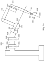
- the assembly 300D includes an automated and motorized setup structure that supports projecting manipulator arms, and may include a base 350 that rests on the floor, a telescoping support column 352 that is mounted on the base, a telescoping boom 354 that extends from the support column 352, and an orienting portion as an orienting platform 356.
- the assembly 300D also includes support beams 358, and several manipulator arms 360 that support surgical tools including portions of the image capture system 108 of FIG. 1 . As shown in FIG.
- manipulator arms 360A, 360B, 360C, 360D are instrument arms that support and move the instruments, such as medical instruments used to manipulate tissue.
- One of these manipulator arms 360 may be designated as a camera arm that supports and moves a camera instrument.
- the camera system may be a stereo endoscope for capturing stereo images of the surgical site and providing the separate stereo images to the display system 202 of FIG. 2 .
- Other implementations of the imaging system are discussed herein.
- manipulator arms that support the instruments and the camera may also be supported by the base 350 or another base, such as a platform (fixed or moveable) mounted to a ceiling or wall, or in some instances to another piece of equipment in the operating room (e.g., an operating table).
- a platform fixed or moveable mounted to a ceiling or wall, or in some instances to another piece of equipment in the operating room (e.g., an operating table).
- two or more physically separate bases may be used (e.g., one base supporting one arm).
- FIGS. 3E and 3F depict embodiments of manipulator assemblies with different platforms.
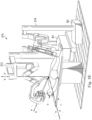
- FIG. 3E is a perspective view of a computer-assisted teleoperated medical system 370 that includes two major components (platforms) that interact with a patient.
- System 370 includes a primary teleoperated platform 372 (also called primary teleoperated assembly 372) that includes several medical instruments and a camera instrument like the assembly 300A of FIG. 3A , system 300C of FIG. 3C , or assembly 300D of FIG. 3D .
- FIG. 3E includes a depiction of system 300C of FIG. 3C as the platform 372, which includes a single manipulator arm.
- other embodiments may include additional manipulator arms, as in assembly 300D of FIG. 3D .
- manipulator arms may each be individually operated by an associated manipulator, such as one of the input devices 204 ( FIG. 2 ) to perform medical tasks at a work site in the patient P, positioned on the table T.
- an associated manipulator such as one of the input devices 204 ( FIG. 2 ) to perform medical tasks at a work site in the patient P, positioned on the table T.
- U.S. Pat. No. 7,955,322, filed Dec. 20, 2006 and entitled "Wireless Communication in a Robotic Surgical System” depicts some examples of a primary teleoperated platform and is incorporated herein by reference in its entirety.
- System 370 also includes a secondary teleoperated platform 374 that may include one or more instruments, each individually operated by an associated manipulator, such as one of the input devices 204 ( FIG. 2 ). In use, the secondary teleoperated surgical platform 374 controls one or more instruments at the surgical site.
- the secondary teleoperated platform 374 may optionally be referred to as being external to the primary teleoperated platform 372.
- each of the primary and secondary platforms is mounted on an individual base, like the base B1 and the base B2.
- the assemblies or platforms may comprise or be mounted to separately movable carts, in some embodiments, so that they can be independently positioned within an operating room or other work environment.
- the secondary platform may be located in various other ways, such as permanently fixed to a mechanical ground (such as a floor, ceiling, or wall), permanently or removably mounted to the operating table, or permanently or removably mounted to the primary platform.
- a mechanical ground such as a floor, ceiling, or wall
- permanently or removably mounted to the operating table or permanently or removably mounted to the primary platform.
- FIG. 3F is a perspective view of another embodiment of a computer-assisted teleoperated system 380.
- a wheeled table T having a table surface is positioned on the table base.
- the table surface can be used to support a work piece such as the patient P or a non-human work piece in other applications.
- two slave manipulator arms 382A and 382B are positioned for operation on the patient P.
- the arms 382A and 382B are supported by arm platforms 384A and 384B that may be removably and repositionably attached to a number of different locations along a table rail 386.
- the controllable arms 382A and 382B are driven to position tools and instruments.
- the instrument 388A may be an imaging system and the instrument 388B may be a pair of forceps for positioning tissue.
- the controllable arms 382A and 382B are teleoperable and include remotely operable powered joints that, when driven, reposition and reorient the tools.
- FIGS. 3E and 3F show configurations in which a manipulator arm and supported instrument on one platform (a primary instrument on a primary platform) may approach a work site from a substantially different side or direction from which an arm and supported instrument on another platform (a secondary instrument on a secondary platform) approaches the work site.
- a manipulator arm and supported instrument on one platform may approach a work site from a substantially different side or direction from which an arm and supported instrument on another platform (a secondary instrument on a secondary platform) approaches the work site.
- the camera instrument may define a field of view
- other instruments may approach the work site from different sides of a plane associated with the field of view.
- Such a configuration can pose problems for providing intuitive control to an operator that is able to control the arms approaching the site from different sides using a single console, like the console 200 of FIG. 2 .
- FIGS. 4A-4B are diagrammatic view of some system components and associated Cartesian frames of reference.
- FIG. 4A shows portions from the operator side of the system.
- FIG. 4B shows portions from the instrument side of the system.
- Frames of reference are also often called “reference frames.”
- frames of reference as discussed in this application are used to explain the different orientations, locations, rotational differences or changes, and translational differences and changes associated with the techniques discussed herein, along with the associated mappings for determining relative locations and orientations, input, and motion commands.
- Some embodiments implementing the described techniques need not use the exact same reference frames in calculations or in operating the system.
- the axes of a reference frame may be set differently from what is described in detail in this disclosure.
- the reference frames may only rotate and not translate.
- other systems may use alternate coordinate systems, such as spherical coordinate systems.
- the imaging system 402 has a field of view 427.
- a work piece 430 and a distal portion of instrument 404 are positioned within the field of view 427.
- the instrument 404 includes a joint 405 and an end effector 406.
- a reference frame 450 has been noted for the shaft of the instrument 404, proximal to the joint 405, and with insertion of the instrument 404 defined as the +Z direction in reference frame 450.
- the reference frame 450 translates and rotates with the translation and rotation of the instrument 404.
- a reference frame 451 has also been noted for the end effector 406, and moves with the end effector 406.
- the reference frames 450 and 451 can be combined into a single reference frame that describes the position and orientation of the relevant portion of the instrument 404 for modeling and/or control.
- FIG. 4B also shows a shaft-based reference frame 453 that translates and rotates with the proximal body of the imaging system 402.
- the reference frames 452 and 453 can be combined into a single reference frame that describes the position and orientation of the relevant portion of the imaging system 402 (such as its field of view 427) for modeling and/or control.
- the kinematic relationship between reference frame 450 or 451 and a reference frame of any other link in the instrument 404 can be determined using well-known kinematic calculations.
- the end effector 406 operates within the field of view 427, so mapping between the reference frames 450 of the end effector 406 and the reference frame 452 of the field of view 427 will allow control of the end effector 406 in the field of view 427.
- FIG. 4A further shows an operator viewing the display system 202 and grasping a master input device 204, as shown in FIG. 2 .
- the display system 202 presents images captured by the imaging system 402 of the field of view 427.
- the display system 202 presents the images as captured, without rotation, panning, zooming, or other manipulation of the images; in this case, a direct, identity mapping can be made between the displayed image and the field of view 427's reference frame 452.
- the display system 202 presents manipulated versions of the images (e.g.
- the mapping between the displayed image and the field of view 427's reference frame 452 takes into account the transformations associated with the manipulation of the image.
- the operator views the instrument 404's position and orientation changes on the display system 202, and establishes a relation between reference frames 454 and 456.
- the operator reference frame is a separate frame that links the reference frames 456 and 454.
- the operator reference frame may be a reference frame based on the eyes, head, torso, other body part, etc. of the operator.
- the operator reference frame may be a reference frame based on a console attached to the master input device 204.
- the operator reference frame is collocated and identical to the reference frame 454, and is essentially the reference frame 454.
- the translations and rotations of the master input device 204 are mapped to the end effector 406 using the reference frames 456 and 450 and kinematic calculations relating the reference frames 456 and 450; as the master input device 204's position or orientation is changed, moving the position or orientation of the reference frame 456, the end effector 406's position or orientation is changed correspondingly (moving the position or orientation of the reference frame 450), so that end effector 406's movement is controlled by to the master input device 204's movement.
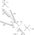
- FIG. 5 also shows a plane 510 that is orthogonal to the line of sight 508.
- the plane 510 is disposed between the imaging system 502 and the secondary platform instrument 506. Envisioning this plane 510 in cases where the configuration of the system allows can be helpful in understanding relative insertion positions and directions, such as by examining how manipulator arms and their associated instruments approach the plane 510.
- the tips of the instruments 504, the tip of the instrument 506, and the tip of the imaging system 502 are positioned such that the tips of the instruments 504 and the imaging system 502 are positioned on a same side of the plane 510. Meanwhile, the tip of the instrument 506 is on an opposite side of the plane 510.
- the instruments 504 are on one side of the plane 510, while the instrument 506 is on the opposite side of the plane 510.
- the longitudinal axes 602 may not lie within, or be parallel to, the X I -Z I plane or the X C -Z C plane.
- the axes 602, and the instruments associated with the axes 602 may or may not be coplanar, may or may not be in parallel planes, and may or may not be parallel.
- the control system 110 may determine orientational differences between the instruments present in the work site. For example, the control system may calculate an angular orientation difference ⁇ 1 between the axis 506A of the imaging system 502 and the axis 602B of the primary support instrument 504B, an angular orientation difference ⁇ 2 between the axis 602A and the axis 602C, and an angular orientation difference ⁇ 3 between the axis 602A and the axis 602D. As shown, the orientation difference ⁇ 1 is about 45°, the orientation difference ⁇ 2 is about 180°, and the ⁇ 3 is about 315°. Before the control system implements movement commands received from one of the input devices 204 of FIG.
- the control system 110 may determine the orientation difference associated with the instrument. The control system 110 may then determine the appropriate commands to implement, based on the orientation difference.
- the orientation difference ⁇ X between the two axes may be determined as the arccosine of the dot product of the axes (e.g. as the inner product of two vectors, each vector representing a direction along one of the two axes). Other methods may also be utilized.
- motion of one of the primary platform instruments 504 is performed in the primary platform's reference frame.
- the motion of a master input device 204 in the operator's (physician's or other user's) reference frame shown in FIG. 4A is mapped to the motion of that primary platform instrument 504 in the platform's reference frame (defined by the field of view of the imaging system 502 and what part of the field of view ).
- a master input device 204 is moved to the right, the system causes a coupled primary platform instrument, either of 504A and 504B in this example, to move to the right relative to the primary platform's reference frame 550.
- motion of a master input device 204 may be mapped to motion of the secondary platform instrument 506 in the secondary platform's reference frame 552 in a reversed (inverted) manner.
- This reversal (inversion) may be implemented in a variety of ways.
- the mapping may include reversing (inverting) motion in at least one axis of the reference frame 552.
- a rotation may be applied in determining instrument 506 motion such that the instrument 506 motion is reversed.
- at least one axis of the reference frame 552 may be reversed when the instrument 506 is inserted oppositely to the imaging system 502.
- a "withdraw” motion on the master input device 204B in a -Z direction relative to the operator frame of reference correspond to a "withdraw” motion of the secondary platform instrument 506 in the platform reference frame 550 and an "insert” motion of the secondary platform instrument 506 in the instrument frame of reference 552.
- a withdraw motion on the master input device 204B which moves the input device 204B toward the operator, is mapped by the system to motion of the secondary platform instrument 506 toward the imaging system 502, and toward the operator's eyes if viewing the display system 202 of FIG. 2 (assuming the display system 202 is showing the image obtained by the imaging system 502).
- a motion to the right on the master input device 204B corresponds to a motion to the left of the secondary platform instrument 506 (relative to the instrument 506), so that the distal end of the secondary platform instrument 506 appears to move to the right in the imaging system 502's field of view.
- a motion to the left on the master input device 204B correspond to a motion to the right of the secondary platform instrument 506 (relative to the instrument 506), so that the distal end of the secondary platform instrument 506 appears to move to the left in the imaging system 502's field of view.
- motion up and down of the master input device 204B still corresponds to motion up and down of the secondary platform instrument 506 as seen by the operator in the display system 202.
- the shaft of the secondary instrument 506 may comprise one or more compliant portions, or may have one or more joints, such that a distal end of the shaft may move differently from a proximal portion of the shaft.
- a distal end of the shaft of the secondary platform instrument 506 moves in the desired direction while the proximal end of the shaft of the secondary platform instrument 506 stays stationary, moves parallel to the desired direction to a different amount, move in a direction opposite direction to the desired direction, etc.
- the distal and proximal ends of the second platform instrument 506 may move in the same direction.
- Table 1 Master input device motion in user's reference frame Primary platform instrument motion in camera reference frame (primary platform reference frame) Secondary platform instrument motion in camera reference frame (primary platform reference frame) Secondary platform instrument motion in secondary platform instrument reference frame +X P +X C +X C -X I -X P -X C -X C +X I +Y P +Y C +Y C +Y I -Y P -Y C -Y C -Y I +Z P +Z C +Z C -Z I -Z P -Z C -Z C +Z I
- the positive and negative directions in the secondary reference frame are defined to correspond to the desired directions of motion in the camera instrument reference frame (and thus with respect to the operator's perspective as facilitated by the display system 202 in various implementations).
- insertion-withdrawal and left-right directions in the secondary platform instrument reference frame can be defined to be the same as the directions of the camera instrument reference frame, in which case the signs would be reversed in Table 1 for the insertion-withdrawal and left-right directions in the secondary platform reference frame.
- the orientation differences between instruments may be determined through any appropriate manner. For example, some implementations use image processing, orientation sensors, kinematic information, shape sensing information, some other technique, or a combination of techniques to determine the orientations or orientation differences between instruments. In all cases, comparison with an orientation difference threshold may be used to select an appropriate transform. For example, as shown in FIG. 6 , the orientation difference between the imaging system 502 and the secondary platform instrument 506 is about 180°; in this example, the control system 110 applies a transform to invert the mapping of the motion of the secondary platform instrument 506 relative to the input device 204 along at least one axis.
- orientation differences below 180° may also be assigned the same transform to invert the mapping of the motion of the secondary platform instrument 506 relative to the input device 204 along at least one axis.
- orientation differences in a range of about 135° to about 225° may be assigned the same transform as shown in Table 1.
- orientation differences in a range of about 120° to about 255° may be assigned a transform shown in table 1.
- the orientation difference may be defined as an absolute orientation difference such that an orientation difference of 240° is processed the same as an orientation difference of 120°, or an orientation difference of 90° is processed the same as an orientation difference of 270°.
- control system 110 may apply different transforms depending on the orientation difference. For example, while the transform shown in Table 1 may be applied to any instruments having an orientation difference relative to the imaging system ranging from about 120° to about 180°, a second transform may be applied to any instruments having an orientation difference relative to the imaging system ranging from about 90° to about 120°, and a third transform may be applied to any instruments having an orientation difference relative to the imaging system ranging from about 270° to about 300°.
- control system 110 may adjust an orientation mapping between input device and instrument, when the instrument has an orientation difference relative to the field of view of the work site that exceeds an adjustment threshold. In some implementations, the control system does not further adjust the orientation mapping. In some implementations, the control system 110 may also adjust the mapping to include an ergonomic offset to facilitate movement by the operator.
- An exemplary offset is shown in FIG. 6 as ⁇ E between the axis 602C of the secondary platform instrument 506 and an axis 604, representing the axis of the shaft of the input device 204 that is to control the secondary platform instrument 506.
- the ergonomic offset may provide for a certain degree of difference between the orientation of the input device 204 assigned to control a particular secondary platform instrument, like the secondary platform instrument 506, and the orientation of that secondary platform instrument. This may be helpful where a mapping without an ergonomic offset is awkward.
- some implementations use an ergonomic offset that emulates the input device holding the shaft of the instrument 506 like a pencil, and enable a pencil-like interaction with the secondary platform instrument 506. As such, the interactions between the input device 204 and the secondary platform instrument 506 resemble the off-axis interaction between pencil and paper when writing, for example.
- the operator may move the input device 204B, for example, to cause movement of the second platform instrument 506 without bringing the shaft 206B into perfect axial alignment with the secondary platform instrument 506.
- An angular ergonomic offset ranging from about 0° to about 50° may be utilized by the control system 110, based on factors such as user selectable adjustments, user preferences, the type of instrument comprising the secondary platform instrument 506, etc.
- this angular ergonomic offset may be implemented as a rotation matrix added to a series of matrices linking the reference frame of the input device 204B and the instrument 506. In some implementations, this is implemented as a rotation of the secondary platform instrument frame 552.
- Embodiments of the present disclosure may include a primary instrument platform and a secondary instrument platform that are connected to separate and movable bases that rests on the floor of the operating room or work environment during operation.
- Embodiments may additionally include primary and secondary instrument platforms that are separate and movable with respect to each other but that are attached to a common structure such as a rail extending alongside a table T.
- Additional embodiments may also include primary and secondary instruments that are secured to a common base or platform, but that approach an work site of opposite sides of a plane orthogonal to a line of sight provided by an endoscopic instrument, such that controlling the secondary instruments in a natural-feeling way requires adjusting or applying a transform to received input commands.
- Embodiments of the present disclosure provide for many different modes of operation.
- One of these mode of operation is depicted in the flowchart of FIG. 7A , which illustrates a method 700A of controlling a robotic system including primary and secondary platforms.
- FIG. 7A illustrates a method 700A of controlling a robotic system including primary and secondary platforms.
- FIG. 7A illustrates a method 700A of controlling a robotic system including primary and secondary platforms.
- Embodiments of the illustrated methods may include additional operations before, after, in between, or as part of the enumerated operations. Additionally, some embodiments of the illustrated methods may omit one or more of the enumerated operations. Moreover, some embodiments of the illustrated methods may include combinations of operations from the depicted methods.
- Some embodiments of the methods include computer readable, non-transient, tangible media having instructions thereon that when executed by a processor, such as the processing device of the control system 110 cause the control system to perform corresponding operations in the context of the described medical systems.
- Some embodiments of the method 700A may begin at an operation 702 in which a processing device of a robotic control system compares an orientation of an instrument with an orientation of a field of view of the instrument workspace.
- the control system 110 may compare the orientation of the secondary platform instrument 506 relative to the orientation of the imaging system 502, which provides a field of view of the workspace to an operator.
- the orientations may be compared by comparing the axis 602A with the axis 602C.
- the orientation difference is determined in view of planes associated with the imaging system 502 and the secondary platform instrument 506, such that only certain components of the axes are compared. As shown, the orientation difference is approximately 180°.
- the control system causes instrument motion in a first direction relative to the instrument frame of reference in response to a movement command.
- a movement command to move the instrument in an insertion direction may be implemented by the control system 110 by moving the instrument in the insertion direction defined relative to the imaging system 502.
- the orientation difference may be a total orientation difference in 3D space, or it may be an orientation difference when the insertion and viewing directions are projected onto a single plane.
- the orientation difference may be when the directions are projected onto the X-Y plane, the X-Z plane, or the Y-Z plane defined by the imaging system reference frame or the instrument reference frame.
- the operator may select a desired orientation threshold prior to operating the system 100.
- Other orientation difference thresholds may be utilized in other embodiments.
- the orientation difference threshold may be defined by a cone or pyramid extending away from the imaging system 502 and centered on a line of sight thereof. Accordingly, the orientation difference threshold may be independent of the role of the imaging system 502 in some embodiments.
- the orientation criterion set may also include factors associated with particular types of instruments. Accordingly, a secondary platform instrument having an ablation end effector may have a different threshold compared to a secondary platform instrument having forceps as its end effector. Additionally, the orientation criterion set may include information to distinguish which instruments are associated with which platform.
- the orientation criterion set may include an indication that the instrument 506 is a secondary platform instrument, in that the instrument 506 is coupled to a system that is characterized by the control system 110 as a second platform. Combinations of these criteria may be used in comparing an instrument to a criterion set.
- the control system causes the instrument motion in a second direction relative to the instrument frame of reference in response to the same movement command.
- the second direction differs from the first direction.
- the second direction may be opposite the first direction.
- Other examples of different directions are shown in Table 1.
- control system 110 may adjust or apply a movement command mapping (also called "transform") when the orientation difference indicates that the secondary platform instrument is positioned opposite an intermediary plane, like the plane 510 shown in FIGS. 5 and 6 , such that it is more natural from the operator's perspective to move the secondary platform instrument in a direction different than would be dictated by the reference frame of the secondary platform instrument.
- a movement command mapping also called "transform”
- the control system 110 may move the imaging system 502 according to the reference frame of the imaging system 502.
- the control system may detect movement of the second master input device in the master workspace.
- the control system 110 may detect movement of the input device 204B.
- the control system 110 may lock out any subsequently detected movement of the first master input device, e.g. the input device 204A, at operation 1416.
- the control system may generate master signals responsive to the movement of the second master input device.
- the control system may map the master workspace to the surgical or other workspace at operation 1420 in order to appropriately generate slave control signals to move the secondary platform instrument in the surgical or other workspace at operation 1422.
- Some embodiments of the method 1500 may begin at operation 1502 in which the control system detects movement of a master input device in a master workspace, the movement being in a first direction.
- the control system 110 may generate master signals responsive to the movement of the master and put device, which may be the input device 204B as shown in FIG. 5 .
- the control system 110 may map the master workspace to the surgical or other workspace, identifying relationships between the operator reference frame or camera reference frame and the instrument reference frame of the instrument being controlled by the master input device.
- the computing system generate control signals to move the external slave manipulator or secondary platform instrument in the work site.
- the control system 110 uses kinematic or non-kinematic sensor information associated with each of the slave manipulator and their associated instruments to determine whether the movement will cause the secondary platform instrument to collide with one of the primary platform instruments. If so, the control system 110 modifies the slave control signals at operation 1512 either or both of the secondary platform instrument and the primary platform instrument in order to avoid the collision. In some embodiments, the control system 110 may modify the slave control signals to cause one slave manipulator to move around the other slave manipulator in order to avoid the collision. This may cause the moving slave manipulator to be moved to the desired location, but via a path that is different than the path dictated by the commanded motion received from the input device 204B.
- some embodiments of the operation 1512 may include moving the slave manipulator that is not associated with the input device 204B, in order to avoid the collision or to alert the operator to enable the operator to avoid the collision.
- the control system 110 may verify a state of the slave manipulator to avoid any additional complications. For example, if the primary slave manipulator has forceps as an end effector, the forceps being closed to grasp tissue, the control system 110 may determine that the forceps or closed and/or grasping tissue and prevent responsive movement of the primary slave manipulator that might otherwise be implementable to avoid the collision.
- the state information may alternatively be able to qualify the movement of the primary slave manipulator, limiting the movement thereof to a wiggle or other motion that is visible to the operator but that will not result in damage to the tissue being grasped.
- the control system may move the external slave manipulator and/or primary slave manipulator in the surgical or other workspace, at operation 1514, as directed by the movement commands produced by the operator interacting with the input devices 204.
- aspects of the current invention may be implemented in surgical or other systems that include two or more operator's consoles, like the console 200, so that a first operator (user) viewing the work site controls a first master manipulator and a second operator (user) viewing the work site controls a second master manipulator.
- the first operator may control the primary platform instruments
- the second operator may control the secondary platform instrument. Both the first and second operators view the same video image from the primary platform camera instrument.
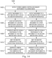
- FIG. 16 includes a method 1600 for controlling robotic manipulators. And the illustrated embodiment of the method 1600 may begin at operation 1602 in which the control system or processing device of the control system to detect that the system is operating in the following mode and is communicating with a primary master controller or console and a secondary master controller or console. In some implementations, the control system may verify that both of the consoles have the same state or mode in effect.
- the control system provides the camera view to the secondary console in addition to the first console.
- the control system 110 may use image analysis and/or kinematic information to determine whether the external instrument or secondary platform instrument is visible in the camera view. When the secondary platform instrument is not visible in the camera view, the control system may abort the following mode at operation 1608.
- the control system may detect movement have a secondary master input device in a secondary master workspace, at operation 1610.
- the control system 110 may detect movement of an input device 204 of the second console, like the console 200 of FIG. 2 .
- the second console may include a master workspace defined by the limits of the motion of the input devices 204.
- the control system generates secondary master signals that are responsive to the movement of the secondary master input device.
- the control system 110 may generate master signals that correspond to the movement of the input device 204B of the second console. These master signals may be movement commands.
- the control system maps the secondary master workspace to the surgical or other workspace. For example, the control system 110 may map or translate the movement commands received from the input device 204B of the second console to an instrument reference frame associated with the instrument, such as the instrument 506 that is to be moved based on the movement commands.
- the transform or transforms may be applied to the movement commands in order to map them to the work site so that they can be appropriately implemented by the instrument 506.
- Implementing movement of the instrument 506 may be the same as implementing movement of a manipulator arm supporting the instrument 506.
- the method 1600 may include checks of individual components of the commanded motion. As shown in FIG. 16 , an X-axis component check is performed at operation 1616, a Y-axis component is checked at operation 1618, and a Z-axis component is checked at 1620.
- the operations 1616, 1618, and 1620 may be performed serially or in parallel by the control system 110. Because commanded motion generally includes components along more than one of the X-axis, Y-axis, and X-axis, the operations 1616, 1618, and 1620 may be performed for any and all commanded motions associated with instruments that can be identified by any criteria, such as the orientation criterion set.
- the transformed control signals may be produced by the control system.
- the transformed control signals may be based on the checks performed at 1616, 1618, and 1620.
- the control system generates slave control signals to move the external instrument or secondary platform instrument 506 in an inverted X-axis direction in the frame of reference of the secondary platform instrument 506.
- the checks at operations 1618 and 1626 may result in the generation of non-inverted signals for the Y-axis (at operation 1624) and in the generation of inverted signals for the Z-axis (at operation 1626.)
- the control system 110 may generate a slave control signals to move the secondary platform instrument in an inverted Y-axis or Z-axis, respectfully, in the frame of reference of the secondary platform instrument 506.
- the checks performed at operations 1616, 1618, and 1620 may rely on a set of criteria, including orientation criteria, to determine whether an inversion modification should be made. For example, the check performed at operation 1618 may determine that operation 1624 should not be performed, i.e.
- an applied transform may modify a movement by an angle that is less than 180°, i.e., that only partially inverts a movement command.
- the secondary platform may include a secondary platform camera instrument, such that two camera instruments are present in a work site.
- the relation of the secondary platform to the primary platform is the same as the relation of the primary platform to the secondary platform as described above.
- the control system 110 maps (or control systems in each of the primary and secondary platforms work together to map) the correct camera reference frame to the correct operator console, and both the first and second operators control the primary and secondary platform instruments as described above, depending on how the primary and secondary platform instruments are coupled to follow motions of the primary and secondary platform master manipulators.
- the control system maps the secondary master workspace to the surgical workspace, interventional site, or other work site as described herein.
- the control system generates slave control signals to move the external slave manipulator/secondary platform instrument in the work site.
- the slave control signals may be produced by adding or multiplying a transform to the master signals, so that they can be implemented appropriately on the secondary platform instrument.
- Embodiments of the present disclosure may facilitate control of secondary platform arms/instruments that have or are likely to have an orientation will difference such that direct implementation of received commands from an operator are likely to result in movements the opposite of those desired by the operator.
- Embodiments of the present disclosure are applicable to systems having separate bases, systems having different platforms but a common base, and to systems having instruments approaching work site from substantially opposite sides of the plane.
- Embodiments of the present disclosure may be modified and such modifications are within the scope of the present disclosure.
- some operational steps like operation 1702 and 1704 are depicted in a particular sequence, but may be performed in another sequence, such as performing operation 1704 before performing operation 1702. Accordingly, such modifications are within the scope and spirit of the present disclosure.
- the present application also includes the following numbered clauses:
Landscapes
- Health & Medical Sciences (AREA)
- Engineering & Computer Science (AREA)
- Life Sciences & Earth Sciences (AREA)
- Surgery (AREA)
- Nuclear Medicine, Radiotherapy & Molecular Imaging (AREA)
- Veterinary Medicine (AREA)
- Medical Informatics (AREA)
- Public Health (AREA)
- General Health & Medical Sciences (AREA)
- Animal Behavior & Ethology (AREA)
- Molecular Biology (AREA)
- Biomedical Technology (AREA)
- Heart & Thoracic Surgery (AREA)
- Robotics (AREA)
- Pathology (AREA)
- Radiology & Medical Imaging (AREA)
- Mechanical Engineering (AREA)
- Gynecology & Obstetrics (AREA)
- Oral & Maxillofacial Surgery (AREA)
- Human Computer Interaction (AREA)
- Physics & Mathematics (AREA)
- Biophysics (AREA)
- Optics & Photonics (AREA)
- Manipulator (AREA)
Applications Claiming Priority (3)
| Application Number | Priority Date | Filing Date | Title |
|---|---|---|---|
| US201662362355P | 2016-07-14 | 2016-07-14 | |
| EP17828568.0A EP3484402B1 (de) | 2016-07-14 | 2017-07-14 | Sekundäre instrumentensteuerung in einem rechnergestützten telebetriebenen system |
| PCT/US2017/042228 WO2018013979A1 (en) | 2016-07-14 | 2017-07-14 | Secondary instrument control in a computer-assisted teleoperated system |
Related Parent Applications (1)
| Application Number | Title | Priority Date | Filing Date |
|---|---|---|---|
| EP17828568.0A Division EP3484402B1 (de) | 2016-07-14 | 2017-07-14 | Sekundäre instrumentensteuerung in einem rechnergestützten telebetriebenen system |
Publications (2)
| Publication Number | Publication Date |
|---|---|
| EP4529882A2 true EP4529882A2 (de) | 2025-04-02 |
| EP4529882A3 EP4529882A3 (de) | 2025-05-14 |
Family
ID=60952213
Family Applications (2)
| Application Number | Title | Priority Date | Filing Date |
|---|---|---|---|
| EP17828568.0A Active EP3484402B1 (de) | 2016-07-14 | 2017-07-14 | Sekundäre instrumentensteuerung in einem rechnergestützten telebetriebenen system |
| EP25150791.9A Pending EP4529882A3 (de) | 2016-07-14 | 2017-07-14 | Sekundäre instrumentensteuerung in einem computergestützten telebetriebenen system |
Family Applications Before (1)
| Application Number | Title | Priority Date | Filing Date |
|---|---|---|---|
| EP17828568.0A Active EP3484402B1 (de) | 2016-07-14 | 2017-07-14 | Sekundäre instrumentensteuerung in einem rechnergestützten telebetriebenen system |
Country Status (6)
| Country | Link |
|---|---|
| US (3) | US11672616B2 (de) |
| EP (2) | EP3484402B1 (de) |
| JP (2) | JP7015256B2 (de) |
| KR (3) | KR102604919B1 (de) |
| CN (2) | CN109195544B (de) |
| WO (1) | WO2018013979A1 (de) |
Families Citing this family (31)
| Publication number | Priority date | Publication date | Assignee | Title |
|---|---|---|---|---|
| ITUB20155057A1 (it) | 2015-10-16 | 2017-04-16 | Medical Microinstruments S R L | Assieme robotico di chirurgia |
| JP6670585B2 (ja) * | 2015-10-30 | 2020-03-25 | Juki株式会社 | 管理装置 |
| KR102604919B1 (ko) | 2016-07-14 | 2023-11-23 | 인튜어티브 서지컬 오퍼레이션즈 인코포레이티드 | 컴퓨터 보조 원격조작 시스템에서의 2차 기구 제어 |
| JP6861604B2 (ja) * | 2017-10-02 | 2021-04-21 | 株式会社オカムラ | 管理システム及び制御方法 |
| US11161243B2 (en) * | 2017-11-10 | 2021-11-02 | Intuitive Surgical Operations, Inc. | Systems and methods for controlling a robotic manipulator or associated tool |
| WO2020223569A1 (en) * | 2019-05-01 | 2020-11-05 | Intuitive Surgical Operations, Inc. | System and method for integrated motion with an imaging device |
| CN110141366A (zh) * | 2019-05-06 | 2019-08-20 | 清华大学 | 运动控制信息流直接传递的血管介入手术机器人执行器 |
| US12446969B2 (en) * | 2019-05-20 | 2025-10-21 | Icahn School Of Medicine At Mount Sinai | Robot mounted camera registration and tracking system for orthopedic and neurological surgery |
| AU2020280022B2 (en) | 2019-05-20 | 2022-08-11 | Icahn School Of Medicine At Mount Sinai | A system and method for interaction and definition of tool pathways for a robotic cutting tool |
| KR20220070212A (ko) * | 2019-09-30 | 2022-05-30 | 마코 서지컬 코포레이션 | 도구의 이동을 안내하기 위한 시스템 및 방법 |
| WO2021131809A1 (en) * | 2019-12-23 | 2021-07-01 | Sony Group Corporation | Computer assisted surgery system, surgical control apparatus and surgical control method |
| WO2021145051A1 (ja) | 2020-01-16 | 2021-07-22 | オリンパス株式会社 | 内視鏡システム |
| JP7105272B2 (ja) * | 2020-04-28 | 2022-07-22 | 川崎重工業株式会社 | 手術支援ロボットおよび手術支援ロボットシステム |
| WO2021257598A1 (en) * | 2020-06-16 | 2021-12-23 | Intuitive Surgical Operations, Inc. | User input systems and methods for a computer-assisted medical system |
| JP7504374B2 (ja) * | 2020-06-19 | 2024-06-24 | Telexistence株式会社 | ロボット制御装置、ロボット制御方法及びロボット制御システム |
| US12251177B2 (en) * | 2020-06-22 | 2025-03-18 | Auris Health, Inc. | Control scheme calibration for medical instruments |
| WO2022104179A1 (en) * | 2020-11-16 | 2022-05-19 | Intuitive Surgical Operations, Inc. | Systems and methods for remote mentoring |
| US12554250B2 (en) * | 2020-11-30 | 2026-02-17 | Intuitive Surgical Operations, Inc. | Haptic profiles for input controls of a computer-assisted device |
| JP7566601B2 (ja) * | 2020-12-03 | 2024-10-15 | 株式会社メディカロイド | ロボット手術システムおよび表示方法 |
| CN114652449B (zh) * | 2021-01-06 | 2026-02-24 | 深圳市精锋医疗科技股份有限公司 | 手术机器人及其引导手术臂移动的方法、控制装置 |
| IT202100003479A1 (it) * | 2021-02-16 | 2022-08-16 | Medical Microinstruments Inc | Metodo per avviare una teleoperazione svolta mediante un sistema robotico per teleoperazione medica o chirurgica, avente un dispositivo master meccanicamente non vincolato e movimentabile da un operatore, con controllo di sistemi di coordinate di riferimento locali |
| GB2605812B (en) * | 2021-04-14 | 2024-03-20 | Prec Robotics Limited | An apparatus, computer-implemented method and computer program |
| CA3215548A1 (en) * | 2021-04-20 | 2022-10-27 | Samuel G. RODRIQUES | Automated drilling device and method |
| JPWO2022230815A1 (de) * | 2021-04-27 | 2022-11-03 | ||
| IT202100016154A1 (it) | 2021-06-21 | 2022-12-21 | Medical Microinstruments Inc | Strumento chirurgico per chirurgia robotica |
| CN114211493B (zh) * | 2021-12-23 | 2023-10-27 | 武汉联影智融医疗科技有限公司 | 机械臂的远程控制系统和方法 |
| DE102022207662A1 (de) * | 2022-07-26 | 2024-02-01 | Kuka Deutschland Gmbh | Kopplungsloser Telebetrieb |
| CN116269786A (zh) * | 2023-03-31 | 2023-06-23 | 艺柏湾医疗科技(上海)有限公司 | 减孔手术体外臂结构 |
| WO2025210565A1 (en) * | 2024-04-04 | 2025-10-09 | Covidien Lp | Surgical robotic system for control of steerable instrument using multiple imaging modalities |
| WO2025231305A1 (en) * | 2024-05-01 | 2025-11-06 | Endoquest Robotics, Inc. | Robotically assisted endoluminal surgical procedures |
| WO2026080318A1 (en) * | 2024-10-08 | 2026-04-16 | Intuitive Surgical Operations, Inc. | View content-based steering of imaging instruments |
Citations (2)
| Publication number | Priority date | Publication date | Assignee | Title |
|---|---|---|---|---|
| US6817974B2 (en) | 2001-06-29 | 2004-11-16 | Intuitive Surgical, Inc. | Surgical tool having positively positionable tendon-actuated multi-disk wrist joint |
| US7955322B2 (en) | 2005-12-20 | 2011-06-07 | Intuitive Surgical Operations, Inc. | Wireless communication in a robotic surgical system |
Family Cites Families (57)
| Publication number | Priority date | Publication date | Assignee | Title |
|---|---|---|---|---|
| US5417210A (en) * | 1992-05-27 | 1995-05-23 | International Business Machines Corporation | System and method for augmentation of endoscopic surgery |
| US5279309A (en) * | 1991-06-13 | 1994-01-18 | International Business Machines Corporation | Signaling device and method for monitoring positions in a surgical operation |
| US5876325A (en) * | 1993-11-02 | 1999-03-02 | Olympus Optical Co., Ltd. | Surgical manipulation system |
| JP3540362B2 (ja) * | 1994-06-14 | 2004-07-07 | オリンパス株式会社 | 手術用マニピュレータの制御システム及びその制御方法 |
| JP3539645B2 (ja) | 1995-02-16 | 2004-07-07 | 株式会社日立製作所 | 遠隔手術支援装置 |
| US5792135A (en) | 1996-05-20 | 1998-08-11 | Intuitive Surgical, Inc. | Articulated surgical instrument for performing minimally invasive surgery with enhanced dexterity and sensitivity |
| US6425865B1 (en) * | 1998-06-12 | 2002-07-30 | The University Of British Columbia | Robotically assisted medical ultrasound |
| US6459926B1 (en) * | 1998-11-20 | 2002-10-01 | Intuitive Surgical, Inc. | Repositioning and reorientation of master/slave relationship in minimally invasive telesurgery |
| US6659939B2 (en) | 1998-11-20 | 2003-12-09 | Intuitive Surgical, Inc. | Cooperative minimally invasive telesurgical system |
| US6424885B1 (en) * | 1999-04-07 | 2002-07-23 | Intuitive Surgical, Inc. | Camera referenced control in a minimally invasive surgical apparatus |
| US6788018B1 (en) | 1999-08-03 | 2004-09-07 | Intuitive Surgical, Inc. | Ceiling and floor mounted surgical robot set-up arms |
| US8271130B2 (en) | 2009-03-09 | 2012-09-18 | Intuitive Surgical Operations, Inc. | Master controller having redundant degrees of freedom and added forces to create internal motion |
| US7594912B2 (en) | 2004-09-30 | 2009-09-29 | Intuitive Surgical, Inc. | Offset remote center manipulator for robotic surgery |
| US8004229B2 (en) | 2005-05-19 | 2011-08-23 | Intuitive Surgical Operations, Inc. | Software center and highly configurable robotic systems for surgery and other uses |
| US6919867B2 (en) * | 2001-03-29 | 2005-07-19 | Siemens Corporate Research, Inc. | Method and apparatus for augmented reality visualization |
| US7747311B2 (en) * | 2002-03-06 | 2010-06-29 | Mako Surgical Corp. | System and method for interactive haptic positioning of a medical device |
| US6978167B2 (en) | 2002-07-01 | 2005-12-20 | Claron Technology Inc. | Video pose tracking system and method |
| JP4542326B2 (ja) | 2003-09-30 | 2010-09-15 | オリンパス株式会社 | カプセル型医療装置誘導システム |
| USD536446S1 (en) | 2004-12-17 | 2007-02-06 | Karl Storz Gmbh & Co. Kg | Uterus manipulator |
| US7763015B2 (en) | 2005-01-24 | 2010-07-27 | Intuitive Surgical Operations, Inc. | Modular manipulator support for robotic surgery |
| US8147503B2 (en) | 2007-09-30 | 2012-04-03 | Intuitive Surgical Operations Inc. | Methods of locating and tracking robotic instruments in robotic surgical systems |
| US9789608B2 (en) | 2006-06-29 | 2017-10-17 | Intuitive Surgical Operations, Inc. | Synthetic representation of a surgical robot |
| US8073528B2 (en) | 2007-09-30 | 2011-12-06 | Intuitive Surgical Operations, Inc. | Tool tracking systems, methods and computer products for image guided surgery |
| WO2007111749A2 (en) * | 2005-12-20 | 2007-10-04 | Intuitive Surgical, Inc. | Method for handling an operator command exceeding a medical device state limitation in a medical robotic system |
| US7835823B2 (en) | 2006-01-05 | 2010-11-16 | Intuitive Surgical Operations, Inc. | Method for tracking and reporting usage events to determine when preventive maintenance is due for a medical robotic system |
| EP2038712B2 (de) | 2006-06-13 | 2019-08-28 | Intuitive Surgical Operations, Inc. | Regelungssystem konfiguriert um nichtideale merkmale einer aktuator-gelenk-koppelung von einem medizinischen robotersystem zu kompensieren |
| US20080064927A1 (en) | 2006-06-13 | 2008-03-13 | Intuitive Surgical, Inc. | Minimally invasrive surgery guide tube |
| US10258425B2 (en) | 2008-06-27 | 2019-04-16 | Intuitive Surgical Operations, Inc. | Medical robotic system providing an auxiliary view of articulatable instruments extending out of a distal end of an entry guide |
| US9718190B2 (en) * | 2006-06-29 | 2017-08-01 | Intuitive Surgical Operations, Inc. | Tool position and identification indicator displayed in a boundary area of a computer display screen |
| JP5444209B2 (ja) * | 2007-04-16 | 2014-03-19 | ニューロアーム サージカル リミテッド | フレームマッピングおよびフォースフィードバックの方法、装置およびシステム |
| US9096033B2 (en) * | 2007-06-13 | 2015-08-04 | Intuitive Surgical Operations, Inc. | Surgical system instrument sterile adapter |
| US8620473B2 (en) | 2007-06-13 | 2013-12-31 | Intuitive Surgical Operations, Inc. | Medical robotic system with coupled control modes |
| US9089256B2 (en) * | 2008-06-27 | 2015-07-28 | Intuitive Surgical Operations, Inc. | Medical robotic system providing an auxiliary view including range of motion limitations for articulatable instruments extending out of a distal end of an entry guide |
| WO2009045827A2 (en) | 2007-09-30 | 2009-04-09 | Intuitive Surgical, Inc. | Methods and systems for tool locating and tool tracking robotic instruments in robotic surgical systems |
| US8864652B2 (en) | 2008-06-27 | 2014-10-21 | Intuitive Surgical Operations, Inc. | Medical robotic system providing computer generated auxiliary views of a camera instrument for controlling the positioning and orienting of its tip |
| KR101038417B1 (ko) | 2009-02-11 | 2011-06-01 | 주식회사 이턴 | 수술 로봇 시스템 및 그 제어 방법 |
| US9492927B2 (en) | 2009-08-15 | 2016-11-15 | Intuitive Surgical Operations, Inc. | Application of force feedback on an input device to urge its operator to command an articulated instrument to a preferred pose |
| KR20110049703A (ko) | 2009-11-04 | 2011-05-12 | 주식회사 이턴 | 수술 로봇 시스템 및 그 복강경 조작 방법 |
| US8521331B2 (en) | 2009-11-13 | 2013-08-27 | Intuitive Surgical Operations, Inc. | Patient-side surgeon interface for a minimally invasive, teleoperated surgical instrument |
| JP5751679B2 (ja) * | 2010-01-15 | 2015-07-22 | マーベル ワールド トレード リミテッド | 圧縮アーチファクトをマスクするためのフィルムグレインの利用 |
| JP5704833B2 (ja) * | 2010-05-10 | 2015-04-22 | オリンパス株式会社 | 操作入力装置およびマニピュレータシステム |
| USD653338S1 (en) | 2010-11-15 | 2012-01-31 | Karl Storz Gmbh & Co. Kg | Uterine manipulator |
| US8918214B2 (en) * | 2011-01-19 | 2014-12-23 | Harris Corporation | Telematic interface with directional translation |
| JP5384545B2 (ja) | 2011-03-07 | 2014-01-08 | 本田技研工業株式会社 | ナビシステム、ナビサーバ、ナビクライアントおよびナビ方法 |
| US9259289B2 (en) | 2011-05-13 | 2016-02-16 | Intuitive Surgical Operations, Inc. | Estimation of a position and orientation of a frame used in controlling movement of a tool |
| US10363102B2 (en) * | 2011-12-30 | 2019-07-30 | Mako Surgical Corp. | Integrated surgery method |
| US10898064B2 (en) * | 2012-03-07 | 2021-01-26 | Transenterix Europe S.A.R.L. | Endoscopic control and maneuvering system in at least two degrees of freedom |
| CN103908346B (zh) | 2012-12-31 | 2016-04-20 | 复旦大学 | 一种高精度自动神经导航空间配准方法 |
| JP2016512733A (ja) * | 2013-03-15 | 2016-05-09 | インテュイティブ サージカル オペレーションズ, インコーポレイテッド | マニピュレータ関節動作を異方的に強調するためにゼロ空間を使用するシステム及び方法 |
| KR20140123122A (ko) * | 2013-04-10 | 2014-10-22 | 삼성전자주식회사 | 수술용 로봇 및 그 제어 방법 |
| WO2014189969A1 (en) * | 2013-05-21 | 2014-11-27 | Camplex, Inc. | Surgical visualization systems |
| EP4005522B1 (de) * | 2014-03-17 | 2025-09-03 | Intuitive Surgical Operations, Inc. | Systeme zur strukturellen anpassung von telebetriebenen medizinischen systemen |
| GB201504787D0 (en) | 2015-03-20 | 2015-05-06 | Cambridge Medical Robotics Ltd | User interface for a robot |
| CN105232155B (zh) * | 2015-09-08 | 2018-11-09 | 微创(上海)医疗机器人有限公司 | 手术机器人调整系统 |
| US10258419B2 (en) | 2015-09-25 | 2019-04-16 | Ethicon Llc | Methods for hybrid robotic laparoscopic surgery |
| US10111721B2 (en) | 2015-09-25 | 2018-10-30 | Ethicon Llc | Hybrid robotic surgery with mirrored and mimicked motion |
| KR102604919B1 (ko) | 2016-07-14 | 2023-11-23 | 인튜어티브 서지컬 오퍼레이션즈 인코포레이티드 | 컴퓨터 보조 원격조작 시스템에서의 2차 기구 제어 |
-
2017
- 2017-07-14 KR KR1020227032845A patent/KR102604919B1/ko active Active
- 2017-07-14 KR KR1020197001943A patent/KR102482803B1/ko active Active
- 2017-07-14 CN CN201780033343.XA patent/CN109195544B/zh active Active
- 2017-07-14 WO PCT/US2017/042228 patent/WO2018013979A1/en not_active Ceased
- 2017-07-14 JP JP2018568357A patent/JP7015256B2/ja active Active
- 2017-07-14 KR KR1020237039660A patent/KR102764208B1/ko active Active
- 2017-07-14 EP EP17828568.0A patent/EP3484402B1/de active Active
- 2017-07-14 EP EP25150791.9A patent/EP4529882A3/de active Pending
- 2017-07-14 CN CN202110737130.3A patent/CN113440263B/zh active Active
- 2017-07-14 US US16/316,859 patent/US11672616B2/en active Active
-
2022
- 2022-01-21 JP JP2022007680A patent/JP7257559B2/ja active Active
-
2023
- 2023-04-28 US US18/309,174 patent/US12446977B2/en active Active
-
2025
- 2025-09-22 US US19/335,077 patent/US20260013954A1/en active Pending
Patent Citations (2)
| Publication number | Priority date | Publication date | Assignee | Title |
|---|---|---|---|---|
| US6817974B2 (en) | 2001-06-29 | 2004-11-16 | Intuitive Surgical, Inc. | Surgical tool having positively positionable tendon-actuated multi-disk wrist joint |
| US7955322B2 (en) | 2005-12-20 | 2011-06-07 | Intuitive Surgical Operations, Inc. | Wireless communication in a robotic surgical system |
Also Published As
| Publication number | Publication date |
|---|---|
| KR20220136456A (ko) | 2022-10-07 |
| JP7015256B2 (ja) | 2022-02-15 |
| CN113440263B (zh) | 2024-03-26 |
| CN113440263A (zh) | 2021-09-28 |
| KR102764208B1 (ko) | 2025-02-07 |
| EP4529882A3 (de) | 2025-05-14 |
| CN109195544B (zh) | 2021-07-20 |
| KR20190018726A (ko) | 2019-02-25 |
| KR20230167129A (ko) | 2023-12-07 |
| JP7257559B2 (ja) | 2023-04-13 |
| EP3484402B1 (de) | 2025-01-15 |
| US11672616B2 (en) | 2023-06-13 |
| CN109195544A (zh) | 2019-01-11 |
| KR102482803B1 (ko) | 2022-12-29 |
| JP2022040387A (ja) | 2022-03-10 |
| WO2018013979A1 (en) | 2018-01-18 |
| EP3484402A4 (de) | 2020-03-25 |
| KR102604919B1 (ko) | 2023-11-23 |
| US20230270510A1 (en) | 2023-08-31 |
| US12446977B2 (en) | 2025-10-21 |
| US20260013954A1 (en) | 2026-01-15 |
| EP3484402A1 (de) | 2019-05-22 |
| US20190314097A1 (en) | 2019-10-17 |
| JP2019527569A (ja) | 2019-10-03 |
Similar Documents
| Publication | Publication Date | Title |
|---|---|---|
| US12446977B2 (en) | Secondary instrument control in a computer-assisted teleoperated system | |
| CN110769773B (zh) | 用于遥控操作的主/从配准和控制 | |
| JP7736243B2 (ja) | 関節動作可能な遠位部分を持つツールを制御するためのシステム及び方法 | |
| KR102410247B1 (ko) | 원격조작 시스템에서 기구 내비게이터를 디스플레이하기 위한 시스템들 및 방법들 | |
| CN113271884A (zh) | 用于与成像设备集成运动的系统和方法 | |
| US20220378528A1 (en) | Systems and methods for controlling a surgical robotic assembly in an internal body cavity | |
| US20250199655A1 (en) | User interface interaction elements with associated degrees of freedom of motion | |
| US20250205900A1 (en) | Setting and using software remote centers of motion for computer-assisted systems | |
| WO2024076592A1 (en) | Increasing mobility of computer-assisted systems while maintaining a partially constrained field of view |
Legal Events
| Date | Code | Title | Description |
|---|---|---|---|
| PUAI | Public reference made under article 153(3) epc to a published international application that has entered the european phase |
Free format text: ORIGINAL CODE: 0009012 |
|
| STAA | Information on the status of an ep patent application or granted ep patent |
Free format text: STATUS: THE APPLICATION HAS BEEN PUBLISHED |
|
| AC | Divisional application: reference to earlier application |
Ref document number: 3484402 Country of ref document: EP Kind code of ref document: P |
|
| AK | Designated contracting states |
Kind code of ref document: A2 Designated state(s): AL AT BE BG CH CY CZ DE DK EE ES FI FR GB GR HR HU IE IS IT LI LT LU LV MC MK MT NL NO PL PT RO RS SE SI SK SM TR |
|
| REG | Reference to a national code |
Ref country code: DE Ref legal event code: R079 Free format text: PREVIOUS MAIN CLASS: A61B0090570000 Ipc: A61B0034350000 |
|
| PUAL | Search report despatched |
Free format text: ORIGINAL CODE: 0009013 |
|
| AK | Designated contracting states |
Kind code of ref document: A3 Designated state(s): AL AT BE BG CH CY CZ DE DK EE ES FI FR GB GR HR HU IE IS IT LI LT LU LV MC MK MT NL NO PL PT RO RS SE SI SK SM TR |
|
| RIC1 | Information provided on ipc code assigned before grant |
Ipc: B25J 13/02 20060101ALI20250404BHEP Ipc: B25J 9/16 20060101ALI20250404BHEP Ipc: A61B 90/57 20160101ALI20250404BHEP Ipc: A61B 17/00 20060101ALI20250404BHEP Ipc: B25J 9/00 20060101ALI20250404BHEP Ipc: A61B 90/00 20160101ALI20250404BHEP Ipc: A61B 34/37 20160101ALI20250404BHEP Ipc: A61B 34/00 20160101ALI20250404BHEP Ipc: A61B 34/35 20160101AFI20250404BHEP |
|
| REG | Reference to a national code |
Ref country code: DE Ref legal event code: R079 Free format text: PREVIOUS MAIN CLASS: A61B0034350000 Ipc: A61B0006000000 |
|
| STAA | Information on the status of an ep patent application or granted ep patent |
Free format text: STATUS: REQUEST FOR EXAMINATION WAS MADE |
|
| GRAP | Despatch of communication of intention to grant a patent |
Free format text: ORIGINAL CODE: EPIDOSNIGR1 |
|
| STAA | Information on the status of an ep patent application or granted ep patent |
Free format text: STATUS: GRANT OF PATENT IS INTENDED |
|
| 17P | Request for examination filed |
Effective date: 20251114 |
|
| RIC1 | Information provided on ipc code assigned before grant |
Ipc: A61B 6/00 20240101AFI20251118BHEP Ipc: A61B 8/08 20060101ALI20251118BHEP Ipc: A61B 8/12 20060101ALI20251118BHEP Ipc: A61B 34/30 20160101ALI20251118BHEP Ipc: A61B 34/20 20160101ALI20251118BHEP Ipc: A61B 34/00 20160101ALI20251118BHEP Ipc: A61B 34/35 20160101ALI20251118BHEP Ipc: A61B 34/37 20160101ALI20251118BHEP Ipc: A61B 90/00 20160101ALI20251118BHEP Ipc: A61B 17/00 20060101ALI20251118BHEP Ipc: A61B 90/57 20160101ALI20251118BHEP Ipc: B25J 9/16 20060101ALI20251118BHEP Ipc: B25J 13/02 20060101ALI20251118BHEP |
|
| INTG | Intention to grant announced |
Effective date: 20251127 |
|
| GRAJ | Information related to disapproval of communication of intention to grant by the applicant or resumption of examination proceedings by the epo deleted |
Free format text: ORIGINAL CODE: EPIDOSDIGR1 |
|
| STAA | Information on the status of an ep patent application or granted ep patent |
Free format text: STATUS: REQUEST FOR EXAMINATION WAS MADE |
|
| GRAP | Despatch of communication of intention to grant a patent |
Free format text: ORIGINAL CODE: EPIDOSNIGR1 |
|
| STAA | Information on the status of an ep patent application or granted ep patent |
Free format text: STATUS: GRANT OF PATENT IS INTENDED |