EP4529406A1 - Thermoelectric conversion element and thermoelectric conversion device - Google Patents
Thermoelectric conversion element and thermoelectric conversion device Download PDFInfo
- Publication number
- EP4529406A1 EP4529406A1 EP23807692.1A EP23807692A EP4529406A1 EP 4529406 A1 EP4529406 A1 EP 4529406A1 EP 23807692 A EP23807692 A EP 23807692A EP 4529406 A1 EP4529406 A1 EP 4529406A1
- Authority
- EP
- European Patent Office
- Prior art keywords
- thermoelectric conversion
- conversion elements
- conversion element
- substrate
- elements
- Prior art date
- Legal status (The legal status is an assumption and is not a legal conclusion. Google has not performed a legal analysis and makes no representation as to the accuracy of the status listed.)
- Pending
Links
Images




Classifications
-
- H—ELECTRICITY
- H10—SEMICONDUCTOR DEVICES; ELECTRIC SOLID-STATE DEVICES NOT OTHERWISE PROVIDED FOR
- H10N—ELECTRIC SOLID-STATE DEVICES NOT OTHERWISE PROVIDED FOR
- H10N15/00—Thermoelectric devices without a junction of dissimilar materials; Thermomagnetic devices, e.g. using the Nernst-Ettingshausen effect
-
- H—ELECTRICITY
- H10—SEMICONDUCTOR DEVICES; ELECTRIC SOLID-STATE DEVICES NOT OTHERWISE PROVIDED FOR
- H10N—ELECTRIC SOLID-STATE DEVICES NOT OTHERWISE PROVIDED FOR
- H10N15/00—Thermoelectric devices without a junction of dissimilar materials; Thermomagnetic devices, e.g. using the Nernst-Ettingshausen effect
- H10N15/20—Thermomagnetic devices using thermal change of the magnetic permeability, e.g. working above and below the Curie point
-
- H—ELECTRICITY
- H10—SEMICONDUCTOR DEVICES; ELECTRIC SOLID-STATE DEVICES NOT OTHERWISE PROVIDED FOR
- H10N—ELECTRIC SOLID-STATE DEVICES NOT OTHERWISE PROVIDED FOR
- H10N19/00—Integrated devices, or assemblies of multiple devices, comprising at least one thermoelectric or thermomagnetic element covered by groups H10N10/00 - H10N15/00
-
- H—ELECTRICITY
- H01—ELECTRIC ELEMENTS
- H01F—MAGNETS; INDUCTANCES; TRANSFORMERS; SELECTION OF MATERIALS FOR THEIR MAGNETIC PROPERTIES
- H01F10/00—Thin magnetic films, e.g. of one-domain structure
- H01F10/08—Thin magnetic films, e.g. of one-domain structure characterised by magnetic layers
- H01F10/10—Thin magnetic films, e.g. of one-domain structure characterised by magnetic layers characterised by the composition
- H01F10/12—Thin magnetic films, e.g. of one-domain structure characterised by magnetic layers characterised by the composition being metals or alloys
- H01F10/126—Thin magnetic films, e.g. of one-domain structure characterised by magnetic layers characterised by the composition being metals or alloys containing rare earth metals
Definitions
- the present invention relates to a thermoelectric conversion element and a thermoelectric conversion device.
- thermoelectric modules are used for converting a temperature difference of a substance into voltage.
- Most thermoelectric modules so far have been based on the Seebeck effect.
- the Seebeck-effect-based modules have not been in widespread use because they have a complex structure and a problem of materials.
- thermoelectric modules based on the anomalous Nernst effect have attracted enormous attention because they have a simple structure and use versatile materials, although the figure of merit in the anomalous Nernst effect is lower than that in the Seebeck effect (e.g., See Patent Literature 1).
- Patent Literature 1 Japanese Laid-Open Patent Publication No. 2021-128998
- the anomalous Nernst effect typically appears in ferromagnets which are very sensitive to an external magnetic field.
- the ferromagnets are less likely to exhibit the anomalous Nernst effect at zero magnetic field regardless of their shapes. Therefore, in order to stably use thermoelectric modules based on the anomalous Nernst effect, it is highly important to use a material that is insensitive to an external magnetic field.
- an object of the invention is to provide a thermoelectric conversion element and a thermoelectric conversion device that are stable against the external magnetic field.
- thermoelectric conversion device includes a substrate and a plurality of thermoelectric conversion elements on the substrate.
- Each of the plurality of thermoelectric conversion elements has a shape extending in one direction, is made of a material that is able to be magnetized in any direction at zero magnetic field, and is configured to exhibit an anomalous Nernst effect.
- the plurality of thermoelectric conversion elements are arranged in parallel to one another in a direction perpendicular to the one direction and electrically connected in series.
- thermoelectric conversion device includes a first substrate; a plurality of first thermoelectric conversion elements on the first substrate, each of the plurality of first thermoelectric conversion elements having a shape extending in one direction, being made of a first material that is able to be magnetized in any direction at zero magnetic field, and being configured to exhibit an anomalous Nernst effect, the plurality of first thermoelectric conversion elements being arranged in parallel to one another in a direction perpendicular to the one direction; a second substrate; and a plurality of second thermoelectric conversion elements on the second substrate, each of the plurality of second thermoelectric conversion elements having a shape extending in the one direction, being made of a second material that is able to be magnetized in any direction at zero magnetic field, and being configured to exhibit the anomalous Nernst effect, the plurality of second thermoelectric conversion elements being arranged in parallel to one another in a direction perpendicular to the one direction.
- thermoelectric conversion by using a material that exhibits the anomalous Nernst effect and is able to be magnetized in any direction at zero magnetic field, it is possible to achieve thermoelectric conversion that is stable against an external magnetic field.
- thermoelectric conversion element according to the embodiments of the invention and a thermoelectric mechanism thereof will be described with reference to FIG. 1 .
- thermoelectric conversion element 1 As shown in FIG. 1 , an assumption is made that a thermoelectric conversion element 1 according to the embodiments has a box shape extending in one direction (direction y), has a predefined thickness (length in a direction z), and is magnetized in a direction +z.
- heat current Q ⁇ -VT
- thermoelectric conversion element 1 When heat current Q ( ⁇ -VT) flows through the thermoelectric conversion element 1 in a direction +x, a temperature difference is created in the direction +x.
- the anomalous Nernst effect generates electromotive force V ( ⁇ M ⁇ (-VT)) in the thermoelectric conversion element 1 in an outer product direction (direction y) perpendicular to both the direction of the heat current Q (direction +x) and the direction of magnetization M (direction +z).
- thermoelectric conversion elements made of a material that is able to be magnetized in any direction at zero magnetic field and configured to exhibit the anomalous Nernst effect.
- magnetic shape anisotropy needs to be small.
- the magnetization needs to be small.
- the magnetization is preferably 2kG (kilogauss) or less, more preferably 1kG or less at a temperature in an actual use environment.
- Ferrimagnets have a magnetization compensation temperature T k , and have two different sublattices. The relative magnitude of magnetization between the sublattices is reversed around T k . For this reason, ferrimagnets have a relatively small magnetization and a weak magnetic shape anisotropy near T k . With this feature, the magnetization of ferrimagnets can be stably oriented in any direction unlike ferromagnets. This tiny magnetization can be stably oriented in any direction, such as a direction perpendicular to or oblique to a longitudinal direction of a thin wire.
- T k of the alloy of a rare-earth element and Co among ferrimagnets is known to lie around room temperature.
- T k is 428K when R is Gd, and T k monotonically decreases with an increase in atomic number of R (Tb, Dy, Ho, Er).
- Tb, Dy, Ho, Er has Curie temperature T c way above room temperature (300K) and remains stable until temperature reaches about 600K to 700K.
- Table 1 and after-mentioned Table 2 are based on the following literature: " Duc N H. Intersublattice Exchange Coupling in The Rare Earth-Transition Metal Intermetallics[J]. Handbook on the Physics and Chemistry of Rare Earths; Gschneidner, KA, Jr., Eyring, L., Eds, 2014: 339-398 .”
- FIG. 2 shows temperature dependence of Hall resistivity for GdCo 3 single crystal, Gd 2 Co 7 single crystal, and GdCo 5 single crystal, and temperature dependence of magnetization for Gd 2 Co 7 single crystal.
- FIG. 2 is based on the following literature: Ogawa A, Katayama T, Hirano M, et al. General Treatment of Anomalous Hall Effect and Kerr Rotation in Rare Earth Cobalt Systems[J]. Japanese Journal of Applied Physics, 1976, 15(S1): 87 .
- R 2 Co 7 has two types of crystal structures: rhombohedral Gd 2 Co 7 -type structure and hexagonal Ce 2 Ni 7 -type structure.
- a length in c-axis of the rhombohedral structure is thus about 1.5 times longer than that of the hexagonal structure.
- Ce 2 Co 7 , Pr 2 Co 7 , Sm 2 Co 7 , and Gd 2 Co 7 can have both rhombohedral and hexagonal structures.
- FIG. 4A shows magnetic field dependence of a Nernst coefficient for Gd 2 Co 7 single crystal at 300K when the magnetic field is applied parallel to c-axis.
- FIG. 4B shows magnetic field dependence of a Nernst coefficient for Ho 1.2 Gd 0.8 Co 7 single crystal at 300K when the magnetic field is applied parallel to c-axis.
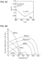
- FIG. 4C shows temperature dependence of magnetization for Ho 1.2 Gd 0.8 Co 7 when the magnetic field of 1T is applied.
- T k of Gd 2 Co 7 is sufficiently higher than room temperature (See Table 1).
- T k of Ho 1.2 Gd 0.8 Co 7 is 278K which is lower than room temperature as shown in FIG. 4C .
- FIGS. 4A and 4B reveal that the Nernst coefficient of Gd 2 Co 7 and the Nernst coefficient of Ho 1.2 Gd 0.8 Co 7 are opposite in sign to each other but share almost the same absolute value at room temperature (300K).
- the absolute value of the Nernst coefficients of both materials is close to the world-record value ( ⁇ 6 ⁇ V/K) at room temperature.
- FIGS. 4A and 4B reflect the fact that Gd 2 Co 7 and Ho 1.2 Gd 0.8 Co 7 have a significantly small magnetization and a large coercive force at room temperature. This indicates that once the magnetization is oriented in a specific direction by the magnetic field, the direction of the magnetization is maintained, which makes it hard to orient the magnetization in the opposite direction. Furthermore, since these materials have a tiny magnetization, the magnetic shape anisotropy is weak. For example, the magnetization can be manipulated in any direction, which is not limited to a longitudinal direction of a thin wire.
- FIG. 4D shows temperature dependence of magnetization for Gd 2 Co 7 , GdCo 2 , GdCo 3 , GdCo 5 , Gd 2.2 Co 16.6 , and Gd 2 Co 17 .
- FIG. 4D is based on the following literature: Katayama T, Shibata T, Magnetic properties of some gadolinium-Cobalt intermetallic compounds[J]. Journal of Magnetism and Magnetic Materials, 1981, 23(2): 173-182 .
- the magnetization value of the ferrimagnet Gd 2 Co 7 is one-tenth to one-fifth the magnetization value of ferromagnets such as GdCo 5 .
- the magnetization value can be further decreased by fine-tuning a composition of rare-earth elements.
- a ternary compound with a smaller magnetization can be obtained, such as Ho 1.2 Gd 0.8 Co 7 shown in FIGS. 4B and 4C . That is, it is possible to obtain a ternary compound with a small magnetization having a composition of R1 2-x R2 x Co 7 (where 0 ⁇ x ⁇ 2, and R1 and R2 are different rare-earth elements from each other).
- thermoelectric conversion element 1 made of a material that is able to be magnetized in any direction at zero magnetic field, such as a ferrimagnet and exhibits the anomalous Nernst effect, it is possible to achieve thermoelectric conversion that is stable against an external magnetic field such as a leak field from a motor.
- thermoelectric conversion devices according to Example 1 and Example 2 each including the thermoelectric conversion element 1 of the embodiments in the form of modules.
- FIG. 5 shows an exterior configuration of a thermoelectric conversion device 100 according to Example 1 of the embodiments.
- the thermoelectric conversion device 100 includes a substrate 22 and a power generator 23 placed on the substrate 22.
- a temperature difference is created in the power generator 23 in the direction of the heat current, and an electric voltage V is generated in the power generator 23 by the anomalous Nernst effect.
- the substrate 22 has a first face 22a on which the power generator 23 is placed, and a second face 22b opposite to the first face 22a. Heat from a heat source (not shown) is applied onto the second face 22b.
- Examples of the material of the substrate 22 include, but are not limited to, MgO, Si, SiO 2 , and Al 2 O.
- the power generator 23 includes a plurality of first thermoelectric conversion elements 24 and a plurality of second thermoelectric conversion elements 25, which are the same in size and have a three-dimensional L shape.
- the first thermoelectric conversion element 24 has the Nernst coefficient which is opposite in sign to the Nernst coefficient of the second thermoelectric conversion element 25.
- the first thermoelectric conversion element 24 and the second thermoelectric conversion element 25 are made of a first material and a second material, respectively, both of which are able to be magnetized in any direction at zero magnetic field.
- the first material and the second material are different ferrimagnets from each other.
- Gd 2 Co 7 FIG. 4A
- Ho 1.2 Gd 0.8 Co 7 FIG. 4B
- the plurality of first thermoelectric conversion elements 24 and the plurality of second thermoelectric conversion elements 25 are alternately arranged in parallel to one another on the substrate 22 in a direction (direction y) perpendicular to a longitudinal direction (direction x) of each thermoelectric conversion element.
- the first thermoelectric conversion element 24 and the second thermoelectric conversion element 25 are arranged such that magnetization M1 of the first thermoelectric conversion element 24 and magnetization M2 of the second thermoelectric conversion element 25 are oriented in an identical direction.
- the number of the first thermoelectric conversion elements 24 and the second thermoelectric conversion elements 25 that constitute the power generator 23 is not restrictive.
- Each of the first thermoelectric conversion elements 24 has one side (+y side) and the other side (-y side) along the longitudinal direction (direction x), and a +x portion on one side is defined as a first end face 24a and a -x portion on the other side is defined as a second end face 24b.
- Each of the second thermoelectric conversion elements 25 has one side (+y side) and the other side (-y side) along the longitudinal direction (direction x), and a -x portion on one side is defined as a first end face 25a and a +x portion on the other side is defined as a second end face 25b.
- the first end face 25a of the second thermoelectric conversion element 25 is connected to the second end face 24b of the first thermoelectric conversion element 24 adjacent thereto in the direction +y, and the second end face 25b of the second thermoelectric conversion element 25 is connected to the first end face 24a of the first thermoelectric conversion element 24 adjacent thereto in the direction -y.
- the plurality of first thermoelectric conversion elements 24 and the plurality of second thermoelectric conversion elements 25 are electrically connected in series to one another. That is, the power generator 23 is placed on the first face 22a of the substrate 22 in a serpentine shape.
- the first thermoelectric conversion element 24 and the second thermoelectric conversion element 25 are electrically insulated from each other except for the connecting portion.
- Example 2 of the embodiments will be explained with reference to FIGS. 6A to 8 .
- Example 1 is directed to the thermoelectric conversion device 100 including the first thermoelectric conversion element 24 and the second thermoelectric conversion element 25, whose Nernst coefficients are opposite in sign to each other, placed on the same face of the substrate 22.
- Example 2 will be directed to a thermoelectric conversion device including such two kinds of thermoelectric conversion elements placed on different substrates.
- the thermoelectric conversion device includes a first structural body 201 shown in FIG. 6A and a second structural body 202 shown in FIG. 6B .
- the first structural body 201 includes a first substrate 210 and a plurality of first thermoelectric conversion elements 231 to 234, which are box-shaped elements with the same size, placed on a first face 211 of the first substrate 210.
- the first thermoelectric conversion elements 231 to 234 are arranged in an equidistant manner in parallel to one another in a direction perpendicular to a longitudinal direction thereof. Similarly, as shown in FIG.
- the second structural body 202 includes a second substrate 220 and a plurality of second thermoelectric conversion elements 241 to 244 placed on a first face 221 of the second substrate 220.
- the second thermoelectric conversion elements 241 to 244 have the same shape and size as those of the first thermoelectric conversion elements 231 to 234, and are arranged in an equidistant manner in parallel to one another in a direction perpendicular to a longitudinal direction thereof.
- These thermoelectric conversion elements are formed on the substrates using, for example, a sputtering method.
- Examples of a material of the first substrate 210 and the second substrate 220 include, but are not limited to, MgO, Si, SiO 2 , and Al 2 O 3 .
- the first thermoelectric conversion elements 231 to 234 are made of a first material
- the second thermoelectric conversion elements 241 to 244 are made of a second material. Nernst coefficients of the first material and the second material are opposite in sign to each other.
- the first material and the second material are able to be magnetized in any direction at zero magnetic field, and are, for example, different ferrimagnets from each other.
- Gd 2 Co 7 FIG. 4A
- Ho 1.2 Gd 0.8 Co 7 FIG. 4B
- thermoelectric conversion elements 231 to 234 are arranged on the first substrate 210, and the four second thermoelectric conversion elements 241 to 244 are arranged on the second substrate 220. Needless to say, the number of the thermoelectric conversion elements on each substrate is not restrictive.
- the first substrate 210 has through-holes that penetrate the first substrate 210 near one end or both ends of each first thermoelectric conversion element in the longitudinal direction. Specifically, as shown in FIG. 7 , the first substrate 210 has a through-hole 272 near one end of the first thermoelectric conversion element 231, through-holes 273 and 274 near both ends of the first thermoelectric conversion element 232, through-holes 275 and 276 near both ends of the first thermoelectric conversion element 233, and through-holes 277 and 278 near both ends of the first thermoelectric conversion element 234.
- the second substrate 220 has through-holes that penetrate the second substrate 220 near one end or both ends of each second thermoelectric conversion element in the longitudinal direction.
- the second substrate 220 has through-holes 281 and 282 near both ends of the second thermoelectric conversion element 241, through-holes 283 and 284 near both ends of the second thermoelectric conversion element 242, through-holes 285 and 286 near both ends of the second thermoelectric conversion element 243, and a through-hole 287 near one end of the second thermoelectric conversion element 244.
- Conductive wires 204 run through each of the through-holes of the first substrate 210 and the second substrate 220.
- Each of the first thermoelectric conversion elements has a first terminal and a second terminal on both ends thereof, and each of the second thermoelectric conversion elements has a first terminal and a second terminal on both ends thereof.
- the conductive wires 204 are connected to the first terminals and the second terminals.
- the first substrate 210 and the second substrate 220 have a second face 212 and a second face 222, respectively, and these second faces are bonded with an adhesive to constitute a thermoelectric conversion device 200 as shown in FIG. 8 .
- a second terminal 252 of the first thermoelectric conversion element 231 is connected to a first terminal 261 of the second thermoelectric conversion element 241 via the through-holes 272 and 281
- a second terminal 262 of the second thermoelectric conversion element 241 is connected to a first terminal 253 of the first thermoelectric conversion element 232 via the through-holes 282 and 273
- a second terminal 254 of the first thermoelectric conversion element 232 is connected to a first terminal 263 of the second thermoelectric conversion element 242 via the through-holes 274 and 283
- a second terminal 264 of the second thermoelectric conversion element 242 is connected to a first terminal 255 of the first thermoelectric conversion element 233 via the through-holes 284 and 275
- a second terminal 256 of the first thermoelectric conversion element 233 is connected to a first terminal 265 of the second thermoelectric conversion element 243 via the through-holes 276 and 285, a second terminal 266 of the second thermoelectric conversion element 243 is connected to a first terminal 257 of the
- thermoelectric conversion elements 231 to 234 and the second thermoelectric conversion elements 241 to 244 are connected alternately and electrically in series.
- first thermoelectric conversion elements 231 to 234 and the second thermoelectric conversion elements 241 to 244 are magnetized in an identical direction (direction +y).
- thermoelectric conversion device 200 when heat current Q flowing in a direction +z through the thermoelectric conversion device 200 creates a temperature difference, the anomalous Nernst effect generates electromotive force in a direction +x in the first thermoelectric conversion elements 231 to 234 and generates electromotive force in a direction -x in the second thermoelectric conversion elements 241 to 244. All of the electromotive forces generated in the thermoelectric conversion elements are added up to output a voltage V between a first terminal 251 of the first thermoelectric conversion element 231 and a second terminal 268 of the second thermoelectric conversion element 244.
- Example 2 by forming the first and second thermoelectric conversion elements having Nernst coefficients which are opposite in sign to each other on different substrates to fabricate the first structural body 201 and the second structural body 202, respectively, it is possible to fabricate the thermoelectric conversion device 200 by a simple process.
- the number of the thermoelectric conversion elements of the thermoelectric conversion device 200 is nearly two times greater than that of the thermoelectric conversion device 100 which includes the first thermoelectric conversion elements 24 and the second thermoelectric conversion elements 25 on the same face of the substrate 22 as demonstrated in Example 1 ( FIG. 5 ). This makes it possible to increase an output voltage.
- the second face 212 of the first substrate 210 and the second face 222 of the second substrate 220 are bonded so that the first face 211 of the first substrate 210 and the first face 221 of the second substrate 220 face opposite directions.
- these first faces 211 and 221 may face the same direction.
- the first substrate 210 and the second substrate 220 may not necessarily have the through-holes.
- the conductive wires 204 may run outside the first substrate 210 and the second substrate 220, provided that the first thermoelectric conversion elements 231 to 234 on the first substrate 210 and the second thermoelectric conversion elements 241 to 244 on the second substrate 220 are connected in series by the conductive wires 204.
Landscapes
- Hall/Mr Elements (AREA)
Applications Claiming Priority (2)
| Application Number | Priority Date | Filing Date | Title |
|---|---|---|---|
| JP2022081825 | 2022-05-18 | ||
| PCT/JP2023/018578 WO2023224091A1 (ja) | 2022-05-18 | 2023-05-18 | 熱電変換素子及び熱電変換デバイス |
Publications (1)
| Publication Number | Publication Date |
|---|---|
| EP4529406A1 true EP4529406A1 (en) | 2025-03-26 |
Family
ID=88835279
Family Applications (1)
| Application Number | Title | Priority Date | Filing Date |
|---|---|---|---|
| EP23807692.1A Pending EP4529406A1 (en) | 2022-05-18 | 2023-05-18 | Thermoelectric conversion element and thermoelectric conversion device |
Country Status (4)
| Country | Link |
|---|---|
| US (1) | US20250324910A1 (https=) |
| EP (1) | EP4529406A1 (https=) |
| JP (1) | JPWO2023224091A1 (https=) |
| WO (1) | WO2023224091A1 (https=) |
Family Cites Families (5)
| Publication number | Priority date | Publication date | Assignee | Title |
|---|---|---|---|---|
| JPS601940B2 (ja) * | 1980-08-11 | 1985-01-18 | 富士通株式会社 | 感温素子材料 |
| WO2012114650A1 (en) * | 2011-02-22 | 2012-08-30 | Panasonic Corporation | Thermoelectric conversion element and producing method thereof |
| JP2021128998A (ja) | 2020-02-13 | 2021-09-02 | 日本電気株式会社 | 熱電変換材料 |
| WO2021215529A1 (ja) * | 2020-04-23 | 2021-10-28 | 国立大学法人東京大学 | 熱電変換素子及び熱電変換装置 |
| JPWO2022092039A1 (https=) * | 2020-10-30 | 2022-05-05 |
-
2023
- 2023-05-18 EP EP23807692.1A patent/EP4529406A1/en active Pending
- 2023-05-18 US US18/865,868 patent/US20250324910A1/en active Pending
- 2023-05-18 WO PCT/JP2023/018578 patent/WO2023224091A1/ja not_active Ceased
- 2023-05-18 JP JP2024521976A patent/JPWO2023224091A1/ja active Pending
Also Published As
| Publication number | Publication date |
|---|---|
| JPWO2023224091A1 (https=) | 2023-11-23 |
| US20250324910A1 (en) | 2025-10-16 |
| WO2023224091A1 (ja) | 2023-11-23 |
Similar Documents
| Publication | Publication Date | Title |
|---|---|---|
| Suryanarayana | Magnetoelectric interaction phenomena in materials | |
| Wurmehl et al. | Valence electron rules for prediction of half-metallic compensated-ferrimagnetic behaviour of Heusler compounds with complete spin polarization | |
| Atzmony et al. | Nonmajor cubic symmetry axes of easy magnetization in rare-earth-iron Laves compounds | |
| Nabi et al. | Study of the magneto-electronic, optical, thermal and thermoelectric applications of double perovskites Ba 2 MTaO 6 (M= Er, Tm) | |
| EP4141976A1 (en) | Thermoelectric conversion element and thermoelectric conversion device | |
| US11917917B2 (en) | Thermoelectric conversion element | |
| US20240284798A1 (en) | Thermoelectric body, thermoelectric generation element, multilayer thermoelectric body, multilayer thermoelectric generation element, thermoelectric generator, and heat flow sensor | |
| US20040114283A1 (en) | Compounds having giant magnetoresistance and spin-polarized tunnels, the production thereof and their use | |
| Apostu et al. | First-order field-induced transition, magnetoresistance, and giant magnetostriction in single crystals of (L a 0.4 Pr 0.6) 1.2 Sr 1.8 Mn 2 O 7 | |
| EP4529406A1 (en) | Thermoelectric conversion element and thermoelectric conversion device | |
| Gotoh et al. | Antiferromagnetism and spin polarization in double perovskite SrLaVMoO6 | |
| JP2021039996A (ja) | 磁性合金材料 | |
| Matsukawa et al. | Anisotropic phonon conduction and lattice distortions in colossal-magnetoresistance bilayer manganite (La 1− z Pr z) 1.2 Sr 1.8 Mn 2 O 7 (z= 0, 0.2, 0.4, and 0.6) single crystals | |
| JP6349863B2 (ja) | スピン流熱電変換素子とその製造方法および熱電変換装置 | |
| Hirone | Magnetic studies at the research institute for iron, steel and other metals | |
| Li et al. | Seeking large Seebeck effects in LaX (X= Mn and Co) O 3/SrTiO 3 superlattices by exploiting high spin-polarized effects | |
| JP2023120825A (ja) | 熱電変換素子 | |
| US8420236B2 (en) | Magnetic semiconductor material | |
| Nam et al. | Low field magnetoresistance in intrinsic granular system La1− xBaxMnO3 | |
| Lofland et al. | Ferromagnetic resonance and magnetization studies on ferrimagnetic double perovskites A/sub 2/FeReO/sub 6/(A= Ca, Sr, Ba) | |
| Janes et al. | Synthesis and Characterization of Single Crystal (Re, Pb) MnO3 Perovskites | |
| Yoneyama et al. | High performance RFeCoZrB bonded magnets having low Nd content | |
| Matsukawa et al. | Anomalous Lattice Distortion in Pr-Substituted Double-Layered Perovskite Manganite La 1.2 Sr 1.8 Mn 2 O 7 Single Crystals: II | |
| Hattori et al. | MAGNETIC PROPERTIES OF $ REPb_ {2} $(RE: LIGHT RARE-EARTH ELEMENT) COMPOUNDS | |
| Gu et al. | Magnetotransport and magnetocaloric properties of La 0.55 Er 0.05 Ca 0.4 MnO 3 |
Legal Events
| Date | Code | Title | Description |
|---|---|---|---|
| STAA | Information on the status of an ep patent application or granted ep patent |
Free format text: STATUS: THE INTERNATIONAL PUBLICATION HAS BEEN MADE |
|
| PUAI | Public reference made under article 153(3) epc to a published international application that has entered the european phase |
Free format text: ORIGINAL CODE: 0009012 |
|
| STAA | Information on the status of an ep patent application or granted ep patent |
Free format text: STATUS: REQUEST FOR EXAMINATION WAS MADE |
|
| 17P | Request for examination filed |
Effective date: 20241218 |
|
| AK | Designated contracting states |
Kind code of ref document: A1 Designated state(s): AL AT BE BG CH CY CZ DE DK EE ES FI FR GB GR HR HU IE IS IT LI LT LU LV MC ME MK MT NL NO PL PT RO RS SE SI SK SM TR |
|
| DAV | Request for validation of the european patent (deleted) | ||
| DAX | Request for extension of the european patent (deleted) | ||
| REG | Reference to a national code |
Ref country code: DE Ref legal event code: R079 Free format text: PREVIOUS MAIN CLASS: H10N0015200000 Ipc: H10N0015000000 |