EP4529352A1 - Trocknungsvorrichtung und aufzeichnungsvorrichtung - Google Patents
Trocknungsvorrichtung und aufzeichnungsvorrichtung Download PDFInfo
- Publication number
- EP4529352A1 EP4529352A1 EP24198479.8A EP24198479A EP4529352A1 EP 4529352 A1 EP4529352 A1 EP 4529352A1 EP 24198479 A EP24198479 A EP 24198479A EP 4529352 A1 EP4529352 A1 EP 4529352A1
- Authority
- EP
- European Patent Office
- Prior art keywords
- drying
- section
- electrode
- frequency voltage
- sections
- Prior art date
- Legal status (The legal status is an assumption and is not a legal conclusion. Google has not performed a legal analysis and makes no representation as to the accuracy of the status listed.)
- Pending
Links
Images




Classifications
-
- F—MECHANICAL ENGINEERING; LIGHTING; HEATING; WEAPONS; BLASTING
- F26—DRYING
- F26B—DRYING SOLID MATERIALS OR OBJECTS BY REMOVING LIQUID THEREFROM
- F26B13/00—Machines and apparatus for drying fabrics, fibres, yarns, or other materials in long lengths, with progressive movement
-
- F—MECHANICAL ENGINEERING; LIGHTING; HEATING; WEAPONS; BLASTING
- F26—DRYING
- F26B—DRYING SOLID MATERIALS OR OBJECTS BY REMOVING LIQUID THEREFROM
- F26B23/00—Heating arrangements
- F26B23/04—Heating arrangements using electric heating
-
- B—PERFORMING OPERATIONS; TRANSPORTING
- B41—PRINTING; LINING MACHINES; TYPEWRITERS; STAMPS
- B41J—TYPEWRITERS; SELECTIVE PRINTING MECHANISMS, i.e. MECHANISMS PRINTING OTHERWISE THAN FROM A FORME; CORRECTION OF TYPOGRAPHICAL ERRORS
- B41J11/00—Devices or arrangements of selective printing mechanisms, e.g. ink-jet printers or thermal printers, for supporting or handling copy material in sheet or web form
- B41J11/0015—Devices or arrangements of selective printing mechanisms, e.g. ink-jet printers or thermal printers, for supporting or handling copy material in sheet or web form for treating before, during or after printing or for uniform coating or laminating the copy material before or after printing
- B41J11/002—Curing or drying the ink on the copy materials, e.g. by heating or irradiating
- B41J11/0021—Curing or drying the ink on the copy materials, e.g. by heating or irradiating using irradiation
-
- B—PERFORMING OPERATIONS; TRANSPORTING
- B41—PRINTING; LINING MACHINES; TYPEWRITERS; STAMPS
- B41J—TYPEWRITERS; SELECTIVE PRINTING MECHANISMS, i.e. MECHANISMS PRINTING OTHERWISE THAN FROM A FORME; CORRECTION OF TYPOGRAPHICAL ERRORS
- B41J11/00—Devices or arrangements of selective printing mechanisms, e.g. ink-jet printers or thermal printers, for supporting or handling copy material in sheet or web form
- B41J11/0015—Devices or arrangements of selective printing mechanisms, e.g. ink-jet printers or thermal printers, for supporting or handling copy material in sheet or web form for treating before, during or after printing or for uniform coating or laminating the copy material before or after printing
- B41J11/002—Curing or drying the ink on the copy materials, e.g. by heating or irradiating
- B41J11/0021—Curing or drying the ink on the copy materials, e.g. by heating or irradiating using irradiation
- B41J11/00216—Curing or drying the ink on the copy materials, e.g. by heating or irradiating using irradiation using infrared [IR] radiation or microwaves
-
- F—MECHANICAL ENGINEERING; LIGHTING; HEATING; WEAPONS; BLASTING
- F26—DRYING
- F26B—DRYING SOLID MATERIALS OR OBJECTS BY REMOVING LIQUID THEREFROM
- F26B13/00—Machines and apparatus for drying fabrics, fibres, yarns, or other materials in long lengths, with progressive movement
- F26B13/10—Arrangements for feeding, heating or supporting materials; Controlling movement, tension or position of materials
-
- F—MECHANICAL ENGINEERING; LIGHTING; HEATING; WEAPONS; BLASTING
- F26—DRYING
- F26B—DRYING SOLID MATERIALS OR OBJECTS BY REMOVING LIQUID THEREFROM
- F26B3/00—Drying solid materials or objects by processes involving the application of heat
- F26B3/32—Drying solid materials or objects by processes involving the application of heat by development of heat within the materials or objects to be dried, e.g. by fermentation or other microbiological action
- F26B3/34—Drying solid materials or objects by processes involving the application of heat by development of heat within the materials or objects to be dried, e.g. by fermentation or other microbiological action by using electrical effects
- F26B3/347—Electromagnetic heating, e.g. induction heating or heating using microwave energy
-
- H—ELECTRICITY
- H05—ELECTRIC TECHNIQUES NOT OTHERWISE PROVIDED FOR
- H05B—ELECTRIC HEATING; ELECTRIC LIGHT SOURCES NOT OTHERWISE PROVIDED FOR; CIRCUIT ARRANGEMENTS FOR ELECTRIC LIGHT SOURCES, IN GENERAL
- H05B6/00—Heating by electric, magnetic or electromagnetic fields
- H05B6/46—Dielectric heating
- H05B6/48—Circuits
- H05B6/50—Circuits for monitoring or control
-
- H—ELECTRICITY
- H05—ELECTRIC TECHNIQUES NOT OTHERWISE PROVIDED FOR
- H05B—ELECTRIC HEATING; ELECTRIC LIGHT SOURCES NOT OTHERWISE PROVIDED FOR; CIRCUIT ARRANGEMENTS FOR ELECTRIC LIGHT SOURCES, IN GENERAL
- H05B6/00—Heating by electric, magnetic or electromagnetic fields
- H05B6/46—Dielectric heating
- H05B6/54—Electrodes
-
- H—ELECTRICITY
- H05—ELECTRIC TECHNIQUES NOT OTHERWISE PROVIDED FOR
- H05B—ELECTRIC HEATING; ELECTRIC LIGHT SOURCES NOT OTHERWISE PROVIDED FOR; CIRCUIT ARRANGEMENTS FOR ELECTRIC LIGHT SOURCES, IN GENERAL
- H05B6/00—Heating by electric, magnetic or electromagnetic fields
- H05B6/46—Dielectric heating
- H05B6/60—Arrangements for continuous movement of material
-
- H—ELECTRICITY
- H05—ELECTRIC TECHNIQUES NOT OTHERWISE PROVIDED FOR
- H05B—ELECTRIC HEATING; ELECTRIC LIGHT SOURCES NOT OTHERWISE PROVIDED FOR; CIRCUIT ARRANGEMENTS FOR ELECTRIC LIGHT SOURCES, IN GENERAL
- H05B6/00—Heating by electric, magnetic or electromagnetic fields
- H05B6/46—Dielectric heating
- H05B6/62—Apparatus for specific applications
Definitions
- the present disclosure relates to a drying device and a recording device.
- a drying device that dries an object by generating the electromagnetic waves with respect to the object, such as JP-A-2017-16742 , is disclosed.
- a drying device can cause the object to generate heat by supplying a high-frequency voltage between a first electrode and a second electrode to generate the electromagnetic waves with respect to the object.
- the heating area is limited in such a drying device, when a heating object having a large area, it is effective to arrange a large number of drying devices. At this time, there is a possibility that the increase of radiation waves may affect the peripheral device. Therefore, it is desired to suppress the influence on surroundings due to the generation of the electromagnetic waves.
- a drying device to solve the above problem includes a plurality of drying sections configured to dry an object by generating electromagnetic waves in response to the application of a high-frequency voltage, wherein each of the plurality of drying sections includes a first electrode, a second electrode disposed so as to surround the first electrode in plan view from a first direction toward the object, a first conductor that has a coil and that is configured to electrically connect a transmission line configured to transmit the high-frequency voltage to the first electrode, and a second conductor configured to electrically connect the transmission line and the second electrode, the drying sections include a first drying section and a second drying section, the first drying section and the second drying section are disposed to be adjacent to each other in a second direction, which intersects the first direction, and a normal phase high-frequency voltage is applied to the first electrode of the first drying section and the second electrode of the second drying section.
- the recording device includes a recording section configured to record on a medium by ejecting liquid onto the medium and a plurality of drying sections configured to dry the medium recorded by the recording section by generating electromagnetic waves in response to the application of a high-frequency voltage
- each of the plurality of drying sections includes a first electrode, a second electrode disposed so as to surround the first electrode in plan view from a first direction toward the medium recorded by the recording section, a first conductor that has a coil and that is configured to electrically connect a transmission line configured to transmit the high-frequency voltage to the first electrode, and a second conductor configured to electrically connect the transmission line and the second electrode
- the drying sections include a first drying section and a second drying section, the first drying section and the second drying section are disposed to be adjacent to each other in a second direction, which intersects the first direction, and a normal phase high-frequency voltage is applied to the first electrode of the first drying section and the second electrode of the second drying section.
- a direction, which intersects a vertical direction Z is referred to as a width direction X and a direction, which intersects the vertical direction Z and a width direction X is referred to as a depth direction Y.
- One direction along the width direction X is referred to as a first width direction X1 and the other direction along the width direction X is referred to as a second width direction X2.
- One direction along the depth direction Y is defined as a first depth direction Y1 and the other direction along the depth direction Y is defined as a second depth direction Y2.
- the vertical direction Z corresponds to an example of a first direction.
- the width direction X corresponds to an example of a second direction.
- the depth direction Y corresponds to an exam ple of a third direction.
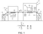
- the recording system 10 is a system for recording on a medium 90.
- the recording system 10 is a system that performs recording on the medium 90 by ejecting liquid onto the medium 90.
- the recording system 10 is a system that dries the medium 90 on which recording has been performed by ejecting a liquid.
- the recording system 10 includes a recording device 11.
- the recording device 11 is configured to perform recording on the medium 90.
- the recording device 11 performs recording on the medium 90 by ejecting liquid onto the medium 90.
- the recording device 11 may be an inkjet printer that performs recording by ejecting ink, which is an example of a liquid, onto the medium 90.
- the medium 90 has a front surface 90A and a back surface 90B.
- the medium 90 is fabric but may be, for example, paper.
- the recording system 10 includes a drying device 12.
- the drying device 12 is configured to dry the medium 90 after the recording in which the recording device 11 ejected the liquid. In particular, by the drying device 12 generates electromagnetic waves to dry the medium 90 after recording.
- the recording system 10 includes a feeding section 13.
- the feeding section 13 feeds the medium 90 before recording to the recording device 11.
- the feeding section 13 includes a feed roller 13A.
- the feed roller 13A extends so as to along the width direction X. In the width direction X, the width of the feed roller 13A is longer than the width of the medium 90.
- the feed roller 13A is configured to rotatably hold a first roll body 91.
- the first roll body 91 is the medium 90 before recording which is wound and stacked.
- the medium 90 may be elongated. In this way, the feed roller 13A holds the medium 90 to be fed to the recording device 11.
- the recording system 10 includes a winding section 14.
- the winding section 14 winds up the medium 90 that has been recorded by the recording device 11.
- the winding section 14 winds up the medium 90 after recording, which has been dried by the drying device 12.
- the winding section 14 includes a winding roller 14A.
- the winding roller 14A is extended along the width direction X. In the width direction X, the width of the winding roller 14A is longer than the width of the medium 90.
- the winding roller 14A is configured to rotatably hold a second roll body 92.
- the second roll body 92 is the medium 90 after recording which is wound and stacked. In this way, the winding roller 14A winds up the medium 90 that has been recorded by the recording device 11 and dried by the drying device 12.
- the recording device 11 includes a recording section 20, a support section 21, and a recording transport section 22.
- the recording section 20 is configured to perform recording on the medium 90 by ejecting the liquid onto the medium 90.
- the recording section 20 is configured to perform recording on the medium 90 by ejecting the liquid onto the front surface 90A of the medium 90.
- the recording section 20 performs recording on the medium 90 supported by the support section 21.
- the recording section 20 perform recording on the medium 90 transported by the recording transport section 22.
- the recording section 20 includes a head 23.
- the head 23 may be a serial head, or may be a line head.
- the serial head is a head that scans in the width direction X of the medium 90.
- the line head is a head that records simultaneously over the width direction X of the medium 90.
- the head 23 includes a nozzle surface 24 in which a plurality of nozzles (not shown) are opened.
- the nozzle surface 24 is a surface facing the lower side Z2.
- the nozzle surface 24 is a surface facing the front surface 90A of the medium 90 transported by the recording transport section 22.
- Each of the plurality of nozzles is configured to open on the lower side Z2.
- Each of the plurality of nozzles is configured to eject the liquid.
- the recording section 20 may include a carriage 25 and a carriage support section 26.
- the carriage 25 is configured to support a head 23.
- the carriage support section 26 is extended so as to along the width direction X.
- the carriage support section 26 supports the carriage 25 so as to be movable along the width direction X.
- the carriage 25 is movable in the width direction X along the carriage support section 26 by driving force from a driving source (not shown).
- the support section 21 is configured to support the medium 90 transported by the recording transport section 22.
- the support section 21 is positioned at the lower side Z2 of the recording section 20.
- the support section 21 supports the back surface 90B of the medium 90 transported by the recording transport section 22.
- the support section 21 is positioned at the lower side Z2 of the head 23.
- the recording transport section 22 is configured to transport the medium 90 in a transport direction D.
- the transport direction D is a direction along the depth direction Y.
- the recording transport section 22 may include a plurality of rollers. Although the recording transport section 22 transports the medium 90 in the transport direction D using the plurality of rollers, the recording transport section 22 may transport the medium 90 in the transport direction D using a transport belt driven by the plurality of rollers.
- the recording transport section 22 may perform intermittent transport in which the transport and stop of the medium 90 are repeated.
- the drying device 12 includes a drying unit 30.
- the drying unit 30 is configured to dry the medium 90 after recording. That is, the drying device 12 uses the medium 90 recorded by the recording section 20 as an object to be dried.
- the drying unit 30 is configured to dry the medium 90 after recording by the generation of the electromagnetic waves.
- the drying unit 30 is positioned on the lower side Z2 of the medium 90, but may be positioned on the upper side Z1 of the medium 90, or may be positioned located both on the upper side Z1 and on the lower side Z2 of the medium 90. In this way, the vertical direction Z is a direction toward the medium 90.
- the drying device 12 includes a high-frequency voltage generation unit 31.
- the high-frequency voltage generation unit 31 is configured to generate a high-frequency voltage.
- the high-frequency voltage generation unit 31 supplies the high-frequency voltage to the drying unit 30.
- the high-frequency voltage generation unit 31 may include a plurality of high-frequency voltage generation sections 39 (to be described later).
- the drying device 12 includes a drying transport section 32.
- the drying transport section 32 is configured to transport the medium 90 in the transport direction D.
- the drying transport section 32 may transport the medium 90 in the transport direction D using a plurality of rollers.
- the drying transport section 32 may perform consecutive transport for consecutively transporting the medium 90. Slackening of the medium 90 may occur between the recording transport section 22 and the drying transport section 32.
- the drying unit 30 is disposed on the lower side Z2 below the medium 90.
- the drying unit 30 dries the medium 90 by heating the medium 90 from the back surface 90B.
- the drying unit 30 includes a plurality of drying sections 33. That is, the drying device 12 includes the plurality of drying sections 33.
- the drying section 33 may be rectangular in plan view.
- the drying section 33 is configured to generate the electromagnetic waves in response to the application of the high-frequency voltage.
- the drying section 33 is configured to dry the medium 90 by generating the electromagnetic waves in response to the application of the high-frequency voltage. That is, the drying section 33 is the electromagnetic wave generation section.
- the drying section 33 generates an alternating electric field by the generation of the electromagnetic waves.
- the electromagnetic waves generated by the drying section 33 are mainly composed of electric fields.
- the drying section 33 can greatly reduce the induction of a magnetic field due to the generated electric fields as compared with the electromagnetic wave generation section that generates normal electromagnetic waves.
- the drying section 33 generates the electromagnetic waves of 2.4GHz, but is not limited to this.
- the drying section 33 may generate, for example, the electromagnetic waves of 3MHz to 300MHz.
- the drying section 33 for example, may generate the electromagnetic waves of 300MHz to 30GHz and may generate the electromagnetic waves of 10MHz to 20GHz among them.
- the drying section 33 includes a plurality of first drying sections 33A and a plurality of second drying sections 33B.
- the first drying section 33A and the second drying section 33B themselves are configured in the same manner.
- a reverse phase high-frequency voltage is applied to the first drying section 33A and the second drying section 33B.
- drying section 33 includes the plurality of first drying sections 33A and the plurality of second drying sections 33B.
- the plurality of drying sections 33 may include the same number of first drying sections 33A and second drying sections 33B.
- the plurality of drying sections 33 are disposed so as to be aligned in the width direction X in each of the multiple rows 34.
- the multiple rows 34 are rows aligned side by side in the depth direction Y.
- the multiple rows 34 include a first row 34A and a second row 34B.
- the plurality of drying sections 33 are disposed such that their long sides extend along the width direction X in a plan view.
- the plurality of drying sections 33 are disposed so as to be separated from each other by a distance d1 in the width direction X in each of the multiple rows 34.
- the plurality of first drying sections 33A and the plurality of second drying sections 33B are disposed so as to be aligned alternately in the width direction X. Specifically, in each of the first row 34A and the second row 34B, the plurality of first drying sections 33A and the plurality of second drying sections 33B are disposed so as to be aligned alternately in the width direction X. That is, the first drying section 33A and the second drying section 33B are disposed so as to be adjacent to each other in the width direction X.
- the drying sections 33 of the first row 34A and the drying sections 33 of the second row 34B are disposed at positions offset by a predetermined distance d2 in the width direction X. Specifically, the first drying sections 33A of the first row 34A and the first drying sections 33A of the second row 34B are disposed at positions separated by the predetermined distance d2 in the width direction X. The second drying sections 33B of the first row 34A and the second drying sections 33B of the second row 34B are disposed at positions separated by the predetermined distance d2 in width direction X.
- the predetermined distance d2 is longer than the distance d1. Therefore, even when the plurality of drying sections 33 are disposed at intervals of the distance d1 in the width direction X in each of the first row 34A and the second row 34B, it is possible to dispose the plurality of drying sections 33 without providing a region in which the drying sections 33 are not disposed in the depth direction Y.
- the drying unit 30 includes an opposing section 35.
- the opposing section 35 is positioned between the medium 90 and the plurality of drying sections 33.
- the opposing section 35 may have a flat plate shape.
- the opposing section 35 is made of a material that transmits the electromagnetic waves generated by the plurality of drying sections 33.
- the opposing section 35 is disposed so as to face the back surface 90B of the medium 90.
- the opposing section 35 may be in contact with the medium 90 and may not be in contact with the medium 90.
- the opposing section 35 protects the plurality of drying sections 33.
- the opposing section 35 is composed of a member having an insulating property.
- the opposing section 35 may be a glass plate.
- the opposing section 35 may be a ceramic with high transmittance.
- the opposing section 35 may be made of a resin with a low dielectric dissipation factor.
- the drying section 33 includes a first electrode 41, a second electrode 42, a first conductor 43, and a second conductor 44.
- Fig. 3 is a diagram excluding a top plate 44C of the second conductor 44 for convenience.
- FIG. 3 is a diagram in which the first electrode 41 and the second electrode 42 are arranged on the upper side Z1.
- the first electrode 41 has a flat plate shape.
- the first electrode 41 may have a rectangular shape in which the width direction X is the longitudinal direction in a plan view.
- the first electrode 41 includes a first electrode surface 41A.
- the first electrode surface 41A is a surface facing the upper side Z1. That is, the first electrode surface 41A is a surface facing the back surface 90B of the medium 90.
- the first electrode 41 is disposed so that the first electrode surface 41A is in contact with the opposing section 35.
- the second electrode 42 has a flat plate shape.
- the second electrode 42 includes a second electrode surface 42A.
- the second electrode surface 42A is a surface facing the upper side Z1. That is, the second electrode surface 42A is a surface facing the back surface 90B of the medium 90.
- the second electrode 42 is disposed so that the second electrode surface 42A is in contact with the opposing section 35.
- the second electrode 42 is provided with an opening section 42B.
- the opening section 42B has a rounded rectangular shape in a plan view.
- the first electrode 41 is positioned in the opening section 42B. That is, the second electrode 42 is disposed so as to surround the first electrode 41 in a plan view from the vertical direction Z.
- the first conductor 43 is configured to electrically connect a transmission line 38 (to be described later) and the first electrode 41.
- the first conductor 43 includes a coil 43A.
- the coil 43A extends in the vertical direction Z.
- One end of the coil 43A is connected to the first electrode 41.
- the other end of the coil 43A is connected to a conductive wire 43B.
- the second conductor 44 is configured to electrically connect the transmission line 38 (to be described later) and the second electrode 42.
- the second conductor 44 may include a support 44A.
- the second conductor 44 may include a plurality of supports 44A.
- the support 44A is electrically connected to the second electrode 42.
- the support 44A extends from the second electrode 42 to the lower side Z2.
- the support 44A is made of metal.
- the second conductor 44 may include a connection section 44B.
- the connection section 44B is electrically connected to the support 44A.
- the connection section 44B is provided at a lower end portion of the support 44A.
- the connection section 44B connects a plurality of supports 44A.
- the connection section 44B may be integral with the support 44A.
- the connection section 44B may be H-shaped in a plan view.
- the connection section 44B is made of metal.
- the second conductor 44 may include the top plate 44C. Since the first electrode 41 and the second electrode 42 are disposed on the upper side Z1, the top plate 44C is positioned on the lower side Z2 of the connection section 44B. The top plate 44C is electrically connected to the connection section 44B. The top plate 44C is provided on the lower side Z2 of the connection section 44B. The top plate 44C may be integral with the connection section 44B. The top plate 44C is made of metal.
- the drying section 33 By configuring the drying section 33 in this way, when the high-frequency voltage is applied to the first electrode 41 and the second electrode 42, the first electrode 41 and the second electrode 42 heat the medium 90 by generating the electromagnetic waves according to the application of the high-frequency voltage.
- the drying section 33 can transmit a large amount of heat energy to the medium 90 due to the generation of the electromagnetic waves.
- the drying section 33 is not of a heat conduction type but of an electromagnetic wave type, and may not include a member such as a heating wire for heating. This makes it possible to reduce the size of the drying section 33.
- the minimum separation distance between the first electrode 41 and the second electrode 42 is equal to or less than 1/10 of the wavelength of the electromagnetic waves output from the drying section 33.
- the electromagnetic waves generated when the high-frequency voltage is applied can be attenuated in the vicinity of the first electrode 41 and the second electrode 42. This makes it possible to reduce the intensity of the electromagnetic waves that reach a distant place from the first electrode 41 and the second electrode 42. That is, the electromagnetic waves generated from the drying section 33 is very strong in the vicinity of the first electrode 41 and the second electrode 42, and is very weak in a distant place.
- Such the drying section 33 by a frequency band of the electromagnetic waves to be generated is appropriately controlled, it is possible to intensively generate an AC electric field in the vicinity of the first electrode 41 and the second electrode 42. In other words, it is possible to suppress the influence on surroundings accompanying the generation of the electromagnetic waves beyond the vicinity of the first electrode 41 and the second electrode 42.
- the vicinity of the first electrode 41 and the second electrode 42 for example, the range of 3mm to 3cm may correspond.
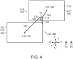
- FIG. 4 is a diagram showing one first drying section 33A and one second drying section 33B and omitting the other drying sections 33 for convenience.
- the first drying section 33A and the second drying section 33B are connected to a connection terminal 37. More specifically, the first drying section 33A in the first row 34A and the second drying section 33B in the second row 34B are connected to the connection terminal 37. The first drying section 33A and the second drying section 33B that overlap each other in the depth direction Y are connected to the connection terminal 37.
- the connection terminal 37 includes a first terminal 37A and a second terminal 37B.
- the first terminal 37A and the second terminal 37B are insulated.
- the transmission line 38 (to be described later) is connectable to the first terminal 37A and the second terminal 37B.
- the first conductor 43 of the first drying section 33A is connected to the first terminal 37A via a first connecting section 36A.
- the second conductor 44 of the first drying section 33A is connected to the second terminal 37B via the second connecting section 36B.
- first conductor 43 of the second drying section 33B is connected to the second terminal 37B via the third connecting section 36C.
- the second conductor 44 of the second drying section 33B is connected to the first terminal 37A via the fourth connecting section 36D.
- first conductor 43 of the first drying section 33A and the second conductor 44 of the second drying section 33B are electrically connected via the first terminal 37A.
- the second conductor 44 of the first drying section 33A and the first conductor 43 of the second drying section 33B are electrically connected via the second terminal 37B.
- FIG. 5 is a diagram showing one first drying section 33A, one second drying section 33B, one connection terminal 37, one transmission line 38, and one high-frequency voltage generation section 39.
- the drying device 12 includes the first drying section 33A, the second drying section 33B, the connection terminal 37, a transmission line 38, and the high-frequency voltage generation section 39.
- the first electrode 41 and the first conductor 43 are connected in the first drying section 33A and the second drying section 33B.
- the second electrode 42 and the second conductor 44 are connected.
- the first conductor 43 of the first drying section 33A is connected to the first terminal 37A of the connection terminal 37.
- the second conductor 44 of the first drying section 33A is connected to the second terminal 37B of the connection terminal 37.
- the first conductor 43 of the second drying section 33B is connected to the second terminal 37B of the connection terminal 37.
- the second conductor 44 of the second drying section 33B is connected to the first terminal 37A of the connection terminal 37.
- the first terminal 37A is connected to a first line 38A of the transmission line 38.
- the second terminal 37B is connected to a second line 38B of the transmission line 38.
- the transmission line 38 is a line that connects the first drying section 33A and the second drying section 33B to the high-frequency voltage generation section 39.
- the transmission line 38 is a line for transmitting the high-frequency voltage generated by the high-frequency voltage generation section 39 to the first drying section 33A and the second drying section 33B. That is, the transmission line 38 is capable of transmitting the high-frequency voltage.
- the transmission line 38 may be a coaxial cable, but is not limited to the coaxial cable.
- the transmission line 38 may provide the first line 38A and the second line 38B.
- the first line 38A may be a core wire of the transmission line 38.
- the second line 38B may be an electromagnetic shield that covers the first line 38A.
- the high-frequency voltage generation section 39 is included in the high-frequency voltage generation unit 31.
- the high-frequency voltage generation section 39 is configured to generate the high-frequency voltage.
- the high-frequency voltage generation section 39 can supply the high-frequency voltage to the first drying section 33A and the second drying section 33B via the transmission line 38 and the connection terminal 37.
- the high-frequency voltage generation section 39 applies the high-frequency voltage to the plurality of drying sections 33.
- the high-frequency voltage generation section 39 is configured to apply the high-frequency voltage to both the first drying section 33A and the second drying section 33B.
- the first electrode 41 of the first drying section 33A is the reverse phase with the first electrode 41 of the second drying section 33B.
- the second electrode 42 of the second drying section 33B is the reverse phase of the first electrode 41 of the second drying section 33B.
- the first electrode 41 of the first drying section 33A is in a normal phase with the second electrode 42 of the second drying section 33B.
- the second electrode 42 of the first drying section 33A is in the normal phase with the first electrode 41 of the first drying section 33A.
- the normal phase high-frequency voltage is applied to the first electrode 41 of the first drying section 33A and the second electrode 42 of the second drying section 33B. That is, the reverse phase high-frequency voltage is applied to the first drying section 33A and the second drying section 33B.
- FIG. 6 is a graph 50 showing the relationship between the number of drying sections 33 and unnecessary radiation waves in the related embodiment and the first embodiment.
- a graph 51 showing the relationship between the number of drying sections 33 and the unnecessary radiation waves in the related embodiment is shown by an one dot chain line.
- a graph 52 showing the relationship between the number of drying sections 33 and the unnecessary radiation waves in the first embodiment is shown by a solid line.
- the first electrode 41 of the first drying section 33A and the first electrode 41 of the second drying section 33B are the normal phases.
- the second electrode 42 of the second drying section 33B and the first electrode 41 of the second drying section 33B are normal phases.
- the first electrode 41 of the first drying section 33A and the second electrode 42 of the second drying section 33B are the reverse phases.
- the second electrode 42 of the first drying section 33A and the first electrode 41 of the first drying section 33A are the reverse phases.
- the first electrode 41 of the first drying section 33A and the first electrode 41 of the second drying section 33B are the reverse phases.
- the second electrode 42 of the second drying section 33B and the first electrode 41 of the second drying section 33B are the reverse phase.
- the first electrode 41 of the first drying section 33A and the second electrode 42 of the second drying section 33B are normal phases.
- the second electrode 42 of the first drying section 33A and the first electrode 41 of the first drying section 33A are normal phases.
- the unnecessary radiation waves do not increase in proportion. In the case of the first embodiment, such an event is caused by the radiation waves from the first drying section 33A and the radiation waves from the second drying section 33B cancel each other.
- the drying device 12 includes the plurality of drying sections 33 that dry the medium 90 by generating the electromagnetic waves in response to the application of the high-frequency voltage.
- the drying section 33 includes the first drying section 33A and the second drying section 33B.
- the first drying section 33A and the second drying section 33B are disposed so as to be adjacent to each other in the width direction X.
- the normal phase high-frequency voltage is applied to the first electrode 41 of the first drying section 33A and the second electrode 42 of the second drying section 33B.
- the radiation waves from the first drying section 33A and the radiation waves from the second drying section 33B cancel each other.
- the radiation waves can be suppressed, it is possible to suppress the influence the peripheral devices. Therefore, it is possible to suppress the influence on surroundings due to the generation of the electromagnetic waves.
- the radiation waves from the first drying section 33A are significantly larger than the radiation waves from the second drying section 33B aligned with the first drying section 33A. Therefore, in the neighboring region where the first drying section 33A is disposed, the radiation waves from the first drying section 33A are not greatly affected by the radiation waves from the second drying section 33B aligned with the first drying section 33A. Accordingly, the radiation waves in the neighboring region where the first drying section 33A is disposed and the radiation waves in the neighboring region where the second drying section 33B is disposed do not largely cancel each other, and the drying qualities are not reduced.
- the drying device 12 includes the plurality of drying sections 33 for drying the medium 90. Therefore, even at a distance from the drying section 33, when the radiation waves from the drying section 33 are amplified by each other, there is a risk that the increase of the radiation waves may affect the peripheral devices. Therefore, by adopting the above configuration, it is possible to suppress the radiation waves even when it is farther than the drying section 33, so that it is possible to suppress the influence on the peripheral devices. Therefore, it is possible to suppress the influence on surroundings due to the generation of the electromagnetic waves.
- the plurality of drying sections 33 include the plurality of first drying sections 33A and the plurality of second drying sections 33B.
- the plurality of first drying sections 33A and the plurality of second drying sections 33B are disposed so as to be aligned alternately in the width direction X.
- the radiation waves from the first drying section 33A and the second drying section 33B cancel each other.
- the radiation waves can be suppressed, it is possible to suppress the influence the peripheral devices. Therefore, it is possible to suppress the influence on surroundings due to the generation of the electromagnetic waves.
- each of the first row 34A and the second row 34B aligned side by side in the depth direction Y the plurality of first drying sections 33A and the plurality of second drying sections 33B are disposed so as to be aligned alternately in the width direction X.
- the first drying sections 33A of the first row 34A and the first drying sections 33A of the second row 34B are disposed at positions separated by the predetermined distance d2 in the width direction X.
- the second drying sections 33B of the first row 34A and the second drying sections 33B of the second row 34B are disposed at positions separated by the predetermined distance d2 in width direction X.
- the plurality of drying sections 33 include the same number of first drying sections 33A and second drying sections 33B. According to this configuration, it is possible to improve the degree to which the radiation waves from the first drying section 33A and the radiation waves from the second drying section 33B cancel each other. As a result, since the radiation waves can be further suppressed, it is possible to suppress the peripheral device. Therefore, it is possible to suppress the influence on surroundings due to the generation of the electromagnetic waves.
- the drying device 12 includes the high-frequency voltage generation section 39 for applying the high-frequency voltage to the plurality of drying sections 33.
- the high-frequency voltage generation section 39 is configured to apply the high-frequency voltage to both the first drying section 33A and the second drying section 33B. According to this configuration, the high-frequency voltage generated by the high-frequency voltage generation section 39 can be applied to both the first drying section 33A and the second drying section 33B. As a result, it is possible to suppress the influence on surroundings due to the generation of the electromagnetic waves and it is possible to reduce the size of the drying device 12.
- Each of the plurality of drying sections 33 are disposed such that their long side extend along the width direction X in a plan view. According to this configuration, it is possible to make it difficult to provide a region in which the drying sections 33 are not disposed in the depth direction Y without increasing the number of the plurality of drying sections 33. Therefore, it is possible to suppress the influence on surroundings due to the generation of the electromagnetic waves and it is possible to improve the drying quality.
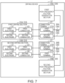
- the high-frequency voltage generation section 39 includes a first high-frequency voltage generation section 39A and a second high-frequency voltage generation section 39B.
- the first high-frequency voltage generation section 39A is connected to the first drying section 33A through the connection terminal 37.
- the second high-frequency voltage generation section 39B is connected to the second drying section 33B via the connection terminal 37. That is, the high-frequency voltage generation section 39 and the drying section 33 are connected in a one-to-one manner.
- the first conductor 43 of the first drying section 33A is connected to the first high-frequency voltage generation section 39A via the first terminal 37A of the connection terminal 37 and the first line 38A of the transmission line 38.
- the second conductor 44 of the first drying section 33A is connected to the first high-frequency voltage generation section 39A via the second terminal 37B of the connection terminal 37 and the second line 38B of the transmission line 38.
- the first conductor 43 of the second drying section 33B is connected to the second high-frequency voltage generation section 39B via the second terminal 37B of the connection terminal 37 and the second line 38B of the transmission line 38.
- the second conductor 44 of the second drying section 33B is connected to the second high-frequency voltage generation section 39B via the first terminal 37A of the connection terminal 37 and the first line 38A of the transmission line 38.
- the first high-frequency voltage generation section 39A is configured to generate the high-frequency voltage.
- the first high-frequency voltage generation section 39A can supply the high-frequency voltage to the first drying section 33A via the transmission line 38 and the connection terminal 37.
- the second high-frequency voltage generation section 39B is configured to generate the high-frequency voltage.
- the second high-frequency voltage generation section 39B can supply the high-frequency voltage to the second drying section 33B via the transmission line 38 and the connection terminal 37.
- the high-frequency voltage generation section 39 can apply the high-frequency voltage to each of the plurality of drying sections 33.
- the high-frequency voltage generation section 39 is configured to apply the high-frequency voltage to the first drying section 33A by the first high-frequency voltage generation section 39A and apply the high-frequency voltage to the second drying section 33B by the second high-frequency voltage generation section 39B.
- the first electrode 41 of the first drying section 33A is the reverse phase with the first electrode 41 of the second drying section 33B.
- the second electrode 42 of the first drying section 33A is the reverse phase with the second electrode 42 of the second drying section 33B.
- the first electrode 41 of the first drying section 33A is in a normal phase with the second electrode 42 of the second drying section 33B.
- the second electrode 42 of the first drying section 33A is the normal phase with the first electrode 41 of the second drying section 33B.
- the normal phase high-frequency voltage is applied to the first electrode 41 of the first drying section 33A and the second electrode 42 of the second drying section 33B. That is, the reverse phase high-frequency voltage is applied to the first drying section 33A and the second drying section 33B.
- the high-frequency voltage generation section 39 includes the first high-frequency voltage generation section 39A and the second high-frequency voltage generation section 39B.
- the first high-frequency voltage generation section 39A applies the high-frequency voltage to the first drying section 33A.
- the second high-frequency voltage generation section 39B applies the high-frequency voltage to the second drying section 33B. According to this configuration, it is possible to apply the high-frequency voltage from the high-frequency voltage generation section 39 to each of the plurality of drying sections 33 on a one-to-one manner. Therefore, it becomes easy to apply the high-frequency voltage of sufficient intensity. As a result, it is possible to suppress the influence on surroundings due to the generation of the electromagnetic waves and it is possible to reduce the size of the drying device 12.
- the present embodiment can be implemented with the following modifications.
- the present embodiment and the following modification examples can be implemented in combination with each other within a technically compatible range.
- the drying section 33 may include at least one first drying section 33A and at least one second drying section 33B. That is, the drying section 33 may include one or more first drying section 33A and one or more second drying section 33B.
Landscapes
- Engineering & Computer Science (AREA)
- Electromagnetism (AREA)
- Physics & Mathematics (AREA)
- Mechanical Engineering (AREA)
- General Engineering & Computer Science (AREA)
- Life Sciences & Earth Sciences (AREA)
- Health & Medical Sciences (AREA)
- Toxicology (AREA)
- Microbiology (AREA)
- General Health & Medical Sciences (AREA)
- Textile Engineering (AREA)
- Sustainable Development (AREA)
- Biotechnology (AREA)
- Molecular Biology (AREA)
- Biomedical Technology (AREA)
- Drying Of Solid Materials (AREA)
- Ink Jet (AREA)
- Constitution Of High-Frequency Heating (AREA)
Applications Claiming Priority (1)
| Application Number | Priority Date | Filing Date | Title |
|---|---|---|---|
| JP2023150800A JP2025043492A (ja) | 2023-09-19 | 2023-09-19 | 乾燥装置及び記録装置 |
Publications (1)
| Publication Number | Publication Date |
|---|---|
| EP4529352A1 true EP4529352A1 (de) | 2025-03-26 |
Family
ID=92675809
Family Applications (1)
| Application Number | Title | Priority Date | Filing Date |
|---|---|---|---|
| EP24198479.8A Pending EP4529352A1 (de) | 2023-09-19 | 2024-09-04 | Trocknungsvorrichtung und aufzeichnungsvorrichtung |
Country Status (4)
| Country | Link |
|---|---|
| US (1) | US20250093099A1 (de) |
| EP (1) | EP4529352A1 (de) |
| JP (1) | JP2025043492A (de) |
| CN (1) | CN119659186A (de) |
Citations (6)
| Publication number | Priority date | Publication date | Assignee | Title |
|---|---|---|---|---|
| JP2017016742A (ja) | 2015-06-26 | 2017-01-19 | 株式会社リコー | 高周波誘電加熱装置及び画像形成装置 |
| JP2021008055A (ja) * | 2019-06-28 | 2021-01-28 | セイコーエプソン株式会社 | インクジェットプリンター |
| JP2023034639A (ja) * | 2021-08-31 | 2023-03-13 | セイコーエプソン株式会社 | 乾燥装置及び記録装置 |
| US20230234375A1 (en) * | 2022-01-25 | 2023-07-27 | Seiko Epson Corporation | Dielectric heating apparatus and printing system |
| US20230241904A1 (en) * | 2022-01-31 | 2023-08-03 | Seiko Epson Corporation | Dielectric Heating Apparatus And Printing System |
| JP2023150800A (ja) | 2022-03-31 | 2023-10-16 | 新電元工業株式会社 | インバータ回路 |
-
2023
- 2023-09-19 JP JP2023150800A patent/JP2025043492A/ja active Pending
-
2024
- 2024-09-04 EP EP24198479.8A patent/EP4529352A1/de active Pending
- 2024-09-16 US US18/886,267 patent/US20250093099A1/en active Pending
- 2024-09-18 CN CN202411301919.4A patent/CN119659186A/zh active Pending
Patent Citations (6)
| Publication number | Priority date | Publication date | Assignee | Title |
|---|---|---|---|---|
| JP2017016742A (ja) | 2015-06-26 | 2017-01-19 | 株式会社リコー | 高周波誘電加熱装置及び画像形成装置 |
| JP2021008055A (ja) * | 2019-06-28 | 2021-01-28 | セイコーエプソン株式会社 | インクジェットプリンター |
| JP2023034639A (ja) * | 2021-08-31 | 2023-03-13 | セイコーエプソン株式会社 | 乾燥装置及び記録装置 |
| US20230234375A1 (en) * | 2022-01-25 | 2023-07-27 | Seiko Epson Corporation | Dielectric heating apparatus and printing system |
| US20230241904A1 (en) * | 2022-01-31 | 2023-08-03 | Seiko Epson Corporation | Dielectric Heating Apparatus And Printing System |
| JP2023150800A (ja) | 2022-03-31 | 2023-10-16 | 新電元工業株式会社 | インバータ回路 |
Also Published As
| Publication number | Publication date |
|---|---|
| CN119659186A (zh) | 2025-03-21 |
| US20250093099A1 (en) | 2025-03-20 |
| JP2025043492A (ja) | 2025-04-01 |
Similar Documents
| Publication | Publication Date | Title |
|---|---|---|
| JP7314657B2 (ja) | インクジェットプリンター | |
| JP7354616B2 (ja) | インクジェットプリンター | |
| JP7413665B2 (ja) | 電磁波発生装置、インク乾燥装置及びインクジェットプリンター | |
| KR101744605B1 (ko) | 어레이 안테나 | |
| WO2014162938A1 (ja) | 液体吐出ヘッド駆動システム | |
| EP4529352A1 (de) | Trocknungsvorrichtung und aufzeichnungsvorrichtung | |
| CN109130505A (zh) | 液体喷出头 | |
| US20260116090A1 (en) | Drying device and recording device | |
| US20260034823A1 (en) | Drying device and recording device | |
| US20250251191A1 (en) | Drying device and recording device | |
| US20250276535A1 (en) | Drying device and recording device | |
| US12291019B2 (en) | Drying device and recording device | |
| CN117465148B (zh) | 介电加热装置及液体喷出系统 | |
| US20250172337A1 (en) | Drying device and recording device | |
| US10052887B1 (en) | Serpentine microwave dryers for printing systems | |
| US20250256518A1 (en) | Drying device and recording device | |
| JP2023108217A (ja) | 誘電加熱装置、および、印刷システム | |
| US20240074009A1 (en) | Dielectric Heating Device And Liquid Ejection System | |
| KR102925945B1 (ko) | 데이터 전송 케이블 및 그를 포함하는 디스플레이 장치 | |
| EP4670993A1 (de) | Trocknungsvorrichtung und aufzeichnungsvorrichtung | |
| CN117325569B (zh) | 感应加热装置以及液体喷出系统 |
Legal Events
| Date | Code | Title | Description |
|---|---|---|---|
| PUAI | Public reference made under article 153(3) epc to a published international application that has entered the european phase |
Free format text: ORIGINAL CODE: 0009012 |
|
| STAA | Information on the status of an ep patent application or granted ep patent |
Free format text: STATUS: THE APPLICATION HAS BEEN PUBLISHED |
|
| AK | Designated contracting states |
Kind code of ref document: A1 Designated state(s): AL AT BE BG CH CY CZ DE DK EE ES FI FR GB GR HR HU IE IS IT LI LT LU LV MC ME MK MT NL NO PL PT RO RS SE SI SK SM TR |
|
| STAA | Information on the status of an ep patent application or granted ep patent |
Free format text: STATUS: REQUEST FOR EXAMINATION WAS MADE |
|
| 17P | Request for examination filed |
Effective date: 20250926 |