EP4528340A1 - Optischer artikel mit einer sehr hochreflektierenden beschichtung im band-35-380 uv - Google Patents
Optischer artikel mit einer sehr hochreflektierenden beschichtung im band-35-380 uv Download PDFInfo
- Publication number
- EP4528340A1 EP4528340A1 EP23306584.6A EP23306584A EP4528340A1 EP 4528340 A1 EP4528340 A1 EP 4528340A1 EP 23306584 A EP23306584 A EP 23306584A EP 4528340 A1 EP4528340 A1 EP 4528340A1
- Authority
- EP
- European Patent Office
- Prior art keywords
- equal
- optical article
- incidence
- layer
- angle
- Prior art date
- Legal status (The legal status is an assumption and is not a legal conclusion. Google has not performed a legal analysis and makes no representation as to the accuracy of the status listed.)
- Pending
Links
Images

Classifications
-
- G—PHYSICS
- G02—OPTICS
- G02B—OPTICAL ELEMENTS, SYSTEMS OR APPARATUS
- G02B1/00—Optical elements characterised by the material of which they are made; Optical coatings for optical elements
- G02B1/10—Optical coatings produced by application to, or surface treatment of, optical elements
- G02B1/11—Anti-reflection coatings
- G02B1/113—Anti-reflection coatings using inorganic layer materials only
- G02B1/115—Multilayers
-
- G—PHYSICS
- G02—OPTICS
- G02B—OPTICAL ELEMENTS, SYSTEMS OR APPARATUS
- G02B5/00—Optical elements other than lenses
- G02B5/08—Mirrors
- G02B5/0891—Ultraviolet [UV] mirrors
-
- G—PHYSICS
- G02—OPTICS
- G02B—OPTICAL ELEMENTS, SYSTEMS OR APPARATUS
- G02B5/00—Optical elements other than lenses
- G02B5/20—Filters
- G02B5/28—Interference filters
- G02B5/283—Interference filters designed for the ultraviolet
-
- G—PHYSICS
- G02—OPTICS
- G02B—OPTICAL ELEMENTS, SYSTEMS OR APPARATUS
- G02B5/00—Optical elements other than lenses
- G02B5/20—Filters
- G02B5/28—Interference filters
- G02B5/285—Interference filters comprising deposited thin solid films
Definitions
- the invention relates to an optical article comprising a base element, such as a substrate, having a front main face and a rear main face, the front main face being coated on its front face with a multilayer interference coating.
- the multilayer interference coating is able to and/or configured to provide a very strong reflection of the ultraviolet range especially between 350-380 nm. Consequently, the front multilayer interference coating allows the transmission of ultraviolet light through the optical article to be decreased.
- the optical article may especially be an ophthalmic lens, in particular a spectacle lens.
- the solar spectrum is composed of electromagnetic radiation of various wavelengths and in particular of ultraviolet (UV) rays.
- the UV spectrum includes a number of bands, in particular the UVA, UVB and UVC bands.
- the UV bands that reach the surface of the Earth are particularly harmful to the eye.
- These bands are in particular responsible for accelerated ocular aging, which can lead to early cataracts or even to more extreme phenomena such as photokeratitis or "snow blindness".
- the UV protection level of an ophthalmic lens is considered to be inadequate when the ophthalmic lens lets pass more than 1% of wavelengths between 280 nm and 380 nm.
- Table 1 below presents examples of the mean reflection factor in the UV band ranging from 280 to 380 nm (Ruv), the mean transmission factor Tuv 280-380 and the ESPF ("Eye Sun Protection Factor"), for bare substrates having various indices for an angle of incidence of 0°.
- Ruv mean reflection factor in the UV band ranging from 280 to 380 nm
- Tuv 280-380 mean transmission factor
- ESPF Erye Sun Protection Factor
- This table1 shows that the lower the refractive index, the lower the Ruv and the higher the Tuv transmission.
- bare ORMA ® substrates have a UV mean transmission factor of around 2.02 % at an angle of incidence of 0° and a mean reflection factor Ruv 280-380 of around 4.30 % at an angle of incidence of 0°). It is also known that this material especially allows ultraviolet light to pass from 350 to 380 nm, so it has a very limited UV protection with an UV cut-off (i.e.: the longest wavelength at which the lens blocks at least 99% of the UV light) around 360 nm. In addition, this kind of substrate has an ESPF of around 16.
- this ORMA ® substrate has a lower UV protection than other substrates having a higher refractive index, such as MR ® 8 substrate (material available from Mitsui Chemicals) having a refractive index of 1.6 and MR ® 7 substrate (material available from Mitsui Chemicals) having a refractive index of 1.67.
- a first solution such as describes in the document FR 2 968 774 , consists in decreasing reflection in the UV spectrum by coating the back face of a lens substrate with a multilayer antireflection coating.
- Another solution allowing a UV-blocking ophthalmic lens to be obtained is to decrease transmission in the UV ( T UV 0 ° % ) , for example by integrating UV absorbers into the ophthalmic lens.
- the UV absorber may be incorporated into the bulk of the lens, during the polymerization of the monomers forming the material of the lens, or be placed on the surface of the latter, by dipping the lens into (or imbibing the lens in) a bath containing the UV absorber.
- incorporation of a UV absorber into a lens is generally accompanied by an undesirable yellowing of the latter, which may be overcome by combining the UV absorber with a specific dye.
- Another known prior-art solution allowing transmission T UV 0 ° % to be decreased consists in coating the substrate with an antireflection stack that rejects ultraviolet rays.
- the document WO 2016/102857 aims at providing a suitable multilayer interference stack that is able to decrease the amount of UV passing through substrates, and in particular for ORMA ® substrates, without however reflecting the visible light and without causing yellowing of the lens (i.e.: the reflectance at 400 nm is relatively low).
- this document discloses a transparent ophthalmic lens comprising a substrate having a front main face and a back main face, the front main face being coated with a multilayer interference coating comprising a stack of at least one layer having a refractive index higher than 1.6, called the high-refractive-index layer (or HI layer), and of at least one layer having a refractive index lower than 1.55, called the low-refractive-index layer (or LI layer), and which does not contain titanium, wherein:
- this document illustrates three examples wherein the front main face of each lens (ORMA ® substrate) is coated with a multilayer interference coating comprising eight layers of alternating HI layer (i.e.: ZrO 2 ) and LI layer (i.e.: SiO 2 ) and one electrically conductive layer of ITO (indium tin oxide).
- a multilayer interference coating comprising eight layers of alternating HI layer (i.e.: ZrO 2 ) and LI layer (i.e.: SiO 2 ) and one electrically conductive layer of ITO (indium tin oxide).
- Table 4 indicates that, at an angle of incidence of 0°, the mean reflection factor in the visible range (i.e.: 380-780), defined as Rv is low and ranges from 0.70% to 0.88%, Ruv (280-380) is high and ranges from 65.4% to 69.5%, Ruv (350-380) is high and ranges from 43% to 62% (Ex.2) and the transmission in the UV ranges Tuv is low and is ranged from 1.18% to 1.34%. (as indicated in this document, this Tuv was only calculated from the Ruv 280-380 of ORMA ® bare substrate, i.e.: 3.87%).
- the Applicant has discovered that, even if the front multilayer interference coating discloses in this document is able to provide suitable optical characteristics to the lens when it is used alone, these optical characteristics are not enough satisfying when it is combined with a standard anti-UV multilayer interference coating having a Ruv lower than 5% for an angle of incidence of 35°disposed on the rear main face of the lens.
- This kind of rear coating is commonly used to protect the eyes of the spectacles wearer from light rays that may reflect onto the lens rear face at oblique incidence (i.e.: from 30 to 45°).
- the UV cut-off is only about 363-364 nm (i.e.: far from 380 nm) and the transmittance at a wavelength of 380 nm, T 380 , is high and ranged from 26% to 37%.
- the UV protection is not enough efficient, and this is all the more problematic when the substrate used has a refractive index below 1.50, such as the widely used ORMA ® substrate having a UV cut-off at 360 nm and that allows ultraviolet light to pass from 350 to 380 nm such as explained above.
- tables 4 and 6 of this document describes Tuv 280-380 values which are of the same and calculated (rather than measured) by 3.87%(1-Ruv), here 3.87% is the UV transmittance of ORMA ® bare substrate.
- the Tuv values in these tables did not take account of UV reflection on the front surface (Cc) and rear surface (Cx) of the tested lenses. Consequently, the results indicated on this table 6 of this document are different from the results described in the experimental part below.
- the document WO 2015/040184 describes a specific interference coating design which reflects the wavelengths in the UV range so as to provide a gradient photochromic tint.
- the lenses (ORMA ® substrates) that are coated with this specific interference coating onto their front main face (i.e.: convex face) have a mean reflectance factor between 330-380 nm ranging from 50% to 79%.
- the Applicant discovers that when a standard UV multilayer interference coating is also applied onto the rear main face (i.e.: concave face) of these lenses, the UV cut-off (i.e.: T% ⁇ 1%) is only around 363-365 nm and the transmittance at 380 nm (T 380 ) is high and about 10%.
- the reflection peak of the illustrated lenses (Ex.1 to Ex.3) of this document extends to 480 nm and their total backward reflection of harmful blue light (Rm B1 within a wavelength range of from 420 to 450 nm) at 35° is undesirably high, such as of 27.64% for Ex.3).
- an object of the current invention is thus to propose a new optical article which avoids, at least in part, the aforementioned drawbacks.
- the objective of the present invention is to provide a transparent optical article, especially an ophthalmic lens, that comprises a base element such as a substrate made of mineral or organic glass including, on its rear main face, a standard UV reflection coating having a mean reflection factor in the UV region ranges from 280 to 380 nm that is lower than 5% for an angle of incidence of 35° that is able or configured to provide, on its front main face, a very high reflectivity in the UV band ranging from 350 nm to 380 nm, and at the same time, having preferably suitable performance in the visible domain and being easy to produce industrially.
- a base element such as a substrate made of mineral or organic glass including, on its rear main face, a standard UV reflection coating having a mean reflection factor in the UV region ranges from 280 to 380 nm that is lower than 5% for an angle of incidence of 35° that is able or configured to provide, on its front main face, a very high reflectivity in the UV band ranging from 350 nm to 380 n
- an object of the current invention is to provide a novel anti-UV multilayered interference coating on a front main face of an optical article, that is able, combined with a standard UV interference coating (different from said front interference coating) disposed on the rear main face of the optical article to decrease the transmission of ultraviolet light, especially in the 350-380 UV range.
- the Applicant sought to develop a new optical article having a very high reflectivity on its front face, especially when the optical article already includes a standard UV reflection coating, and this so as to prevent the ocular damage caused by these UV rays, especially, but not dedicated specifically for a base element having a refractive index which is lower than 1.59 and/or has a mean transmission factor in the region ranging from 350 to 380 nm that is higher than 0.0004% at an angle of incidence of 0°.
- the base element is a substrate selected from materials obtained by (co)polymerization of di(ethylene glycol) bis(allyl carbonate) and corresponds for instance ORMA ® substrate.
- the invention refers to an optical article, defined as OA, having a front main face and a rear main face, comprising at least:
- a method, or a step in a method that "comprises,” “has,” “contains,” or “includes” one or more steps or elements possesses those one or more steps or elements, but is not limited to possessing only those one or more steps or elements.
- the indication of an interval of values « from X to Y » or "between X to Y”, according to the present invention, means as including the values of X and Y.
- ophthalmic article defined by, but not exclusive of corrective lenses, non-corrective lenses, contact lenses, intra-ocular lenses, magnifying lenses, protective lenses, and visors containing photochromic compounds within a coating, the lens material, a film, or any adjacent layer.
- a base element can consist in an optical, such as an ophthalmic, substrate or in a support film of optical quality to be fixed on an optical/ophthalmic substrate thanks to an adhesive such as a pressure-sensitive adhesive of optical quality (PSA layer) (i.e.: laminate).
- PSA layer pressure-sensitive adhesive of optical quality
- the expression "to deposit a layer or a coating onto the article” is intended to mean that a layer or a coating is deposited onto the external (exposed) surface of the outer coating of the article, that is to say its coating that is the most distant from the substrate.
- a coating that is said to be “on” a substrate/base element or deposited “onto” a substrate/base element” is defined as a coating, which (i) is positioned above the substrate/base element, (ii) is not necessarily in contact with the substrate/base element, that is to say one or more intermediate coatings may be arranged between the substrate/base element and the coating in question, and (iii) does not necessarily completely cover the substrate/base element.
- the coating on a substrate or deposited onto a substrate is in direct contact with this substrate.
- a layer 1 is lying under a layer 2
- layer 2 is more distant from the substrate than layer 1.
- outermost layer of the interferential coating it is meant the layer of the interferential coating which is the furthest from the substrate.
- innermost layer of the interferential coating it is meant the layer of the interferential coating which is the closest to the substrate.
- inner layer of the interferential coating it is meant any layer of the interferential coating except for the outermost layer of said interferential coating.
- a layer of the interferential coating is defined as having a thickness higher than or equal to 1 nm. Thus, any layer having a thickness lower than 1 nm will not be considered when counting the number of layers in the reflective coating. A sub-layer is also not considered when counting the number of layers of the interferential coating.
- the refractive indexes referred to in the present application are expressed at 25 °C at a wavelength of 550 nm.
- the rear (or the inner or Concave or CC) face of the base element substrate is intended to mean the face which, when using the article, is the nearest from the wearer's eye. It is generally a concave face.
- the front face of the substrate (or Convex or CX), is the face which, when using the article, is the most distant from the wearer's eye. It is generally a convex face.
- a "transparent substrate” is understood to be transparent, when the observation of an image through said substrate is perceived with no significant loss of contrast, that is, when the formation of an image through said substrate is obtained without adversely affecting the quality of the image.
- the colorimetric coefficients of the optical article of the invention in the international colorimetric system CIE L*a*b* (1976) are calculated between 380 and 780 nm, taking the standard illuminant D 65 and the observer into account (angle of 10°).
- the observer is a "standard observer" as defined in the international colorimetric system CIE L*a*b*. Indeed, in the CIE L*a*b* space, it is possible to express not only overall variations in color, but also in relation to one or more of the parameters L*, a* and b*. This can be used to define new parameters and to relate them to the attributes of the visual sensation.
- Clarity related to luminosity, is directly represented by the value of L*.
- Chroma: C* (a* 2 + b* 2 ) 1/2 defines the chromaticness.
- the angle of hue: h tg-1 (b*/a*) (expressed in degrees); related to hue.
- the mean reflection factor weighted by the function W( ⁇ ) may be defined between two wavelengths ⁇ 1 and ⁇ 2 if the equation above is rewritten and the limits of the integral set equal to the wavelengths ⁇ 1 and ⁇ 2, such as for instance ⁇ 1 equal to 350nm and ⁇ 2 equal to 380 nm, such as to obtain Ruv 350-380 .
- Rm B1 can be measured for any angle of incidence of 35° on the rear man face of the optical article, based on R( ⁇ ) measured at the same angle of incidence.
- R m B2 is defined for a specific angle of incidence, preferably 35° (on the rear main face of the OA), based on R( ⁇ ) measured at the same angle of incidence.
- the mean transmission factor Tuv 280-380 takes into account all means blocking light between 280 and 380 nm and is defined for a specific angle of incidence, preferably 0° (on the rear main face of the OA), based on T( ⁇ ) measured at the same angle of incidence.
- the maximum reflectance R max over the whole spectrum corresponds to the maximum reflectance value (highest value) measured on the whole spectrum ranging from 280 nm to 780 nm.
- ESPF is commercially divided into segments, and is broken down into six categories in the following manner (table 2): Table 2 ESPF Class ESPF ⁇ 6.25 Class 0 ESPF 6.25-12.5 Class 10 ESPF 12.5-20 Class 15 ESPF 20-30 Class 25 ESPF 30-50 Class 35 ESPF > Class 50
- the "angle of incidence (symbol ⁇ )" is the angle formed by a ray light incident on an ophthalmic lens surface and a normal to the surface at the point of incidence.
- the ray light is for instance an illuminant light source, such as the standard illuminant D65 as defined in the international colorimetric CIE L*a*b* (1976).
- the angle of incidence changes from 0° (normal incidence) to 90° (grazing incidence).
- the usual range for angle of incidence is from 0° to 75° and is typically of 0°, 15° or 35° for the present invention.
- the Applicant has developed a transparent optical article, especially an ophthalmic lens such as spectacle lens, comprising a base element, such as a substrate in mineral or organic glass coated, on its rear main face, with a standard UV reflection coating and, on its front main face, with the multilayered coating according to the invention, said transparent optical article has a super high reflectivity in the UV band, and especially in the UV band ranging from 350 to 380 nm and a very low transmittance between 350 and 380 nm which is lower than0.25%, showing an extremely high level of UV protection.
- the Applicant has shown that the new multilayer interference coating IC1 according to the invention allows, surprisingly, the amount of UV passing through substrates, and in particular ORMA ® substrates, to be decreased, without however reflecting visible light and without causing yellowing of the optical article.
- the Applicant has also shown that the new multilayer interference coating IC1 according to the invention allows ESPF to be greatly increased, without however increasing reflectance in the visible.
- this new anti-UV multilayer interference coating IC1 is easy to implement. In particular, it is easier to implement than the UV absorbers that must be incorporated into the substrate. In addition, the required materials are the same as those required for standard antireflection coatings.
- optical article defined as OA, having a front main face and a rear main face, comprising at least:
- the optical article according to the present invention comprises a base element.
- this base element can be a laminate, that is to say a support film of optical quality to be fixed on an optical/ophthalmic substrate thanks to an adhesive such as a pressure-sensitive adhesive of optical quality (PSA layer).
- PSA layer a pressure-sensitive adhesive of optical quality
- the support film is made of cellulose triacetate (TAC) and has a thickness of at least 40 microns, preferably a thickness in the range of 40 ⁇ m to 300 ⁇ m inclusive and preferably a thickness of 80 to 190 ⁇ m.
- Materials of the support film may be selected from the group of films made of cellulose triacetate (TAC), cellulose acetate butyrate (CAB), polycarbonate (PC), poly(ethylene terephthalate) (PET), poly(methylmethacrylate) (PMMA), urethane polymer (TPU), cyclo olefin copolymer (COC), polyester copoblock amide (like Pebax) and Polyimides.
- TAC cellulose triacetate
- CAB polycarbonate
- PET poly(ethylene terephthalate)
- PMMA poly(methylmethacrylate)
- TPU urethane polymer
- COC cyclo olefin copolymer
- polyester copoblock amide like Pebax
- Polyimides cellulose triacetate (TAC), cellulose acetate butyrate (CAB), polycarbonate (PC), poly(ethylene terephthalate) (PET), poly(methylmethacrylate) (PMMA), urethane polymer (
- the base element can consist in an ophthalmic substrate of a transparent optical article, such as a lens or lens blank, and more preferably an ophthalmic lens or lens blank.
- the interferential coating of the optical article according to the invention may be deposited onto any substrate, and preferably onto organic lens substrates, for example a thermoplastic or thermosetting plastic material.
- Thermoset materials may be selected from, for instance: cycloolefin copolymers such as ethylene/norbornene or ethylene/cyclopentadiene copolymers ; homo- and copolymers of allyl carbonates of linear or branched aliphatic or aromatic polyols, such as homopolymers of diethylene glycol bis(allyl carbonate) (CR 39 ® ) ; homo- and copolymers of (meth)acrylic acid and esters thereof, which may be derived from bisphenol A ; polymer and copolymer of thio(meth)acrylic acid and esters thereof, polymer and copolymer of allyl esters which may be derived from Bisphenol A or phthalic acids and allyl aromatics such as styrene, polymer and copolymer of urethane and thiourethane, polymer and copolymer of epoxy, and polymer and copolymer of sulphide, disulfide and epi
- a (co)polymer is intended to mean a copolymer or a polymer.
- a (meth)acrylate is intended to mean an acrylate or a methacrylate.
- a polycarbonate is intended to mean either homopolycarbonates or copolycarbonates and block copolycarbonates.
- the bare base element i.e.: a base element as such and/or which are not coated with any interference coatings
- a “base element having a refractive index which is lower than 1.59” includes the following values and/or any intervals comprised between these values (limits included): 1.58; 1.57; 1.56; 1.55; 1.54; 1.53; 1.52; 1.51; 1.50; 1.49; etc.
- a "base element having a Tuv 350-380 (BE) which is higher than 0.0004%” includes the following values (in %) and/or any intervals comprised between these values (limits included): 0.00045; 00050; 00051; 0,0060; 0,0070; 0,0080; 0,0090; 0,01; 0,02; 0,03; 0,04; 0,05; 0,06; 0,07; 0,08; 0,09; 0,1; 0,2; 0,3; 0,4; 0,5; 0,6; 0,7; 0,8; 0,9; 1,0; 1,1; 1, 2; 1,3; 1,4; 1,5, 1,6; 1,7; 1,8; 1,9; 2,0; etc.
- the base element recommended for the invention is a substrate selected from materials obtained by (co)polymerization of di(ethylene glycol) bis(allyl carbonate) and may correspond to the CR-39 ® ESSILOR ORMA ® lenses.
- the substrate may be coated with one or more functional coatings prior to depositing the interferential coating IC1 of the invention and/or the standard UV reflection coating IC2.
- These functional coatings traditionally used in optics may be, without limitation, an impact-resistant primer layer, an abrasion-resistant coating (that is different from the claimed external abrasion-resistant coating), a polarizing coating, a photochromic coating or a tinted coating.
- a substrate means either a bare substrate or such a coated substrate.
- the surfaces of the underlying layers can be submitted to specific treatments, so as to reinforce the adhesion of one layer to the next one.
- Such treatment can be a physical or chemical surface activating pre-treatment that is generally conducted under vacuum. It may be a bombardment with energetic and/or reactive species, for example with an ion beam ("Ion Pre-Cleaning" or "IPC") or with an electron beam, a corona discharge treatment, an ion spallation treatment, an ultraviolet treatment or a plasma-mediated treatment under vacuum, generally using an oxygen or an argon plasma. It may also be an acid or basic treatment and/or a solvent-based treatment (water, hydrogen peroxide or any organic solvent).
- the interferential coating IC1 according to the invention enables to improve the optical characteristics of an optical article comprising, on its rear main face, a standard UV reflecting interference coating IC2 having a mean reflection factor Ruv (IC2) in the UV region ranges from 280 to 380 nm that is lower than 5% for an angle of incidence of 35°.
- IC1 according to the invention is especially designed to possess very high reflective performances in the UV region, especially such as between 350 to 380 nm, while preferably being able to minimize the reflection in the visible domain.
- IC1 comprises a front main face (i.e.: main face that is the furthest from the substrate) having a mean reflection factor Ruv 350-380 (IC1) in the UV region ranges from 350 to 380 nm for an angle of incidence within the range of from 0° to 15°, and preferably of 0° which is higher than or equal to 75%, in particular higher than or equal to 80%, preferably higher than or equal to 85%, more preferably higher than or equal to 88% and typically higher than or equal to 90%.
- Ruv 350-380 IC1
- a "mean reflection factor Ruv 350-380 (IC1) for an angle of incidence within the range of from 0° to 15°" which is higher than 75% includes the following values (in %) and/or any intervals comprised between these values (limits included): 75; 76; 77; 78; 79; 80; 81; 82; 83; 84; 85; 86; 87; 88; 89; 90; 91; 92; 93; 94; 95; 96; 97; 98; 99; etc.
- This mean reflection factor R UV(IC1) on the front main face of IC1 may also be named hereafter the “forward mean reflection factor Ruv (IC1) ".
- the UV reflection between 350 to 380 nm on the front main face of IC1 according to the invention is very high whatever the angle of incidence.
- the forward mean reflection factor Ruv 350-380 (IC1) on the front main face of IC1 in the UV region ranges from 350 to 380 nm whatever the angle of incidence within the range of from 0° to 60°, is higher than or equal to 68%, in particular higher than or equal to 69%, preferably higher than or equal to 70%, more preferably higher than or equal to 71% and typically higher than or equal to 72%.
- a forward "mean reflection factor Ruv 350-380 (IC1) for an angle of incidence within the range of from 0° to 60°" which is higher than 68% includes the following values (in %) and/or any intervals comprised between these values (limits included): 68; 69; 70; 71; 72; 73; 74; 75; 76; 77; 78; 79; 80; 81; 82; 83; 84; 85; 86; 87; 88; 89; 90; 91; 92; 93; 94; 95; 96; 97; 98; 99; etc.
- the spectral reflectivity curve on the main front face of the IC1 according to the invention generally has, in the wavelength range from 320 nm to 420 nm, a "bell" shape.
- IC1 has, on its front main face, a reflectance curve having a maximum reflectance, defined as R max IC1 within the 350-410 nm range, typically, within the 370-390 nm range for an angle of incidence ranging from 0° to 15°, preferably of 0°.
- R max IC1 on the front main face of IC1 for an angle of incidence within the range of from 0° to 15°, and preferably of 0°, is higher than or equal to 80%, in particular higher than or equal to 85%, preferably higher than or equal to 90%, more preferably higher than or equal to 95% and typically higher than or equal to 98%.
- the reflectance at 380 nm, defined as R 380 (IC1) on the front main face of IC1 for an angle of incidence within the range of from 0° to 15°, and preferably of 0°, is also higher than or equal to 80%, in particular higher than or equal to 85%, preferably higher than or equal to 90%, more preferably higher than or equal to 95% and typically higher than or equal to 98%.
- the reflection peak of the front main face of IC1 is centred on around 380 nm and hence R max IC1 corresponds generally to R 380 (IC1) .
- a "R 380 (IC1) or R max IC1 which is higher than 80%” includes the following values (in %) and/or any intervals comprised between these values (limits included): 80; 81; 82; 83; 84; 85; 86; 87; 88; 89; 90; 91; 92; 93; 94; 95; 96; 97; 98; 99; etc.
- IC1 has, on its front main face, a reflectance curve decreasing from 90% to 10% at a rate higher than or equal to 1.5 %/nm, preferably at a rate higher than or equal to 1.6 %/nm, more preferably at a rate higher than or equal to 2.0 %/nm and typically preferably at a rate higher than or equal to 2.10 %/nm.
- a rate higher than or equal to 1.5 %/nm includes the following values (in %/nm) and/or any intervals comprised between these values (limits included): 1.5; 1.51; 1.52; 1.53; 1.54; 1.55; 1.56; 1.57; 1.58; 1.59; 1.60; 1.61; 1.62; 1.63; 1.64; 1.65; 1.66; 1.67; 1.68; 1.69; 1.70; 1.75; 1.80; 1.85; 1.90; 1.95; 2.00; 2.05; 2.10; 2.15; 2.20; 2.25; 2.30; 2.35; 2.40; 2.45; 2.50; 2.55; 2.60; 2.65; 2.70; 2.75; 2.76; 2.77; 2.78; 2.89; 2.80; etc.
- IC1 has, on its front main face, a reflectance curve decreasing from 80% to 20% at a rate higher than or equal to 1.8 %/nm, preferably at a rate higher than or equal to 2.0 %/nm, more preferably at a rate higher than or equal to 2.10 %/nm and typically preferably at a rate higher than or equal to 2.15 %/nm.
- a rate higher than or equal to 1.8 %/nm includes the following values (in %/nm) and/or any intervals comprised between these values (limits included): 1.80; 1.85; 1.90; 1.95; 2.00; 2.05; 2.10; 2.15; 2.20; 2.25; 2.30; 2.35; 2.40; 2.45; 2.50; 2.55; 2.60; 2.65; 2.70; 2.75; 2.76; 2.77; 2.78; 2.89; 2.80; 2.85; 2.90; 2.95; 3.00; 3.05; 3.10; 3.15; 3.20; 3.25; 3.30; 3.35; 3.40; 3.45; 3.50; 3.55; etc.
- the "bell" shape of the spectral reflectivity curve on the main front face of the IC1 can be characterized by its height (maximum reflectivity, R max ) and its width at mid-height (FWHM or "Full Width at Half Maximum”).
- the FWHM is lower than or equal to 150 nm, especially lower than or equal to 140 nm, preferably lower than or equal to 130 nm and typically lower than or equal to 120 nm.
- a rate higher than or equal to 1.8 %/nm includes the following values (in %/nm) and/or any intervals comprised between these values (limits included): 1.80; 1.85; 1.90; 1.95; 2.00; 2.05; 2.10; 2.15; 2.20; 2.25; 2.30; 2.35; 2.40; 2.45; 2.50; 2.55; 2.60; 2.65; 2.70; 2.75; 2.76; 2.77; 2.78; 2.89; 2.80; 2.85; 2.90; 2.95; 3.00; 3.05; 3.10; 3.15; 3.20; 3.25; 3.30; 3.35; 3.40; 3.45; 3.50; 3.55; 3.60; etc.
- the IC1 according to the invention has very good performances in the visible domain between 380 to 780 nm, that is to say, it enables to strongly reduce the forward reflection in the visible domain.
- the IC1 coating has on its front main face, a mean light reflection factor in the visible region Rv (IC1) for an angle of incidence of within the range of rom 0° to 15° that is lower than or equal to 2.0 %, in particular lower than or equal to 1.5%, preferably lower than or equal to 1.0%, more preferably lower than or equal to 0.90% and typically lower than or equal to 0.85%, such as for instance lower than or equal to 0.80%.
- IC1 mean light reflection factor in the visible region Rv (IC1) for an angle of incidence of within the range of rom 0° to 15° that is lower than or equal to 2.0 %, in particular lower than or equal to 1.5%, preferably lower than or equal to 1.0%, more preferably lower than or equal to 0.90% and typically lower than or equal to 0.85%, such as for instance lower than or equal to 0.80%.
- the IC1 coating blocks less than 10 % or 6 % of light having a wavelength ranging from 465 to 495 nm (B2).
- IC1 has, on its front main face for an angle of incidence ranging from 0° to 15° an average blue light reflection factor Rm B1 (IC1 front fac) within a wavelength range of from 420 nm to 450 nm, which is higher than or equal to 5 %, preferably higher than or equal to 8.0%, in particular higher than or equal to 10.0%, and preferably an average blue light reflection factor Rm B1 (IC1 front face) lower than or equal to 40.0%, in particular lower than or equal to 35.0% and typically lower than or equal to 30.0%.
- Rm B1 average blue light reflection factor
- IC1 has, on its rear main face for an angle of incidence ranging from 35°, an average blue light reflection factor Rm B1 (IC1 rear face) within a wavelength range of from 420 nm to 450 nm for an angle of incidence of 35°, which is lower than or equal to 10.0%, especially lower than or equal to 8.0%, in particular lower than or equal to 7.5%.
- Rm B1 average blue light reflection factor
- IC1 has, on its front main face for an angle of incidence ranging from 0° to 15° (preferably at 15°) an average blue light reflection factor Rm B2 (IC1 front fac) within a wavelength range of from 465 nm to 495 nm, which is lower than or equal to 10.0%, preferably lower than or equal to 9.0%, in particular lower than or equal to 8.0%, and typically lower than or equal to 6%.
- Rm B2 average blue light reflection factor
- IC1 has, on its front main face for an angle of incidence ranging from 0° to 15° an average blue light reflection factor Rm B3 (IC1 front fac) within a wavelength range of from 440 nm to 460 nm, which is higher than or equal to 1.0%, preferably higher than or equal to 1.5 %, in particular higher than or equal to 2.0%, and typically higher than or equal to 2.5%.
- Rm B3 average blue light reflection factor
- IC1 comprises at least one layer, preferably two layers having a low refractive index which is lower than 1.55, defined as "LI layer”, and at least one layer, preferably two layers having a high refractive index which is equal to or higher than 1.55, defined as "HI layer”. It is here a simple stack, since the layer total number in the interferential coating is higher than or equal to 2 and in general lower than or equal to 16.
- the total number of HI and LI layers in the interferential coating IC1 is higher than or equal to 5, preferably higher than or equal to 6, more preferably higher than or equal to 7 and typically higher than or equal to 8.
- the total number of HI and LI layers in the interferential coating IC1 is lower than or equal to 16, especially lower than or equal to preferably lower than or equal to 15, more preferably lower than or equal to 13 and typically lower than or equal to 12.
- the HI layers and LI layers alternate with each other in the stack of the interferential coating IC1 according to the invention.
- IC1 has a total physical thickness lower than or equal to 1 ⁇ m, in particular lower than or equal to 900 nm and typically lower than or equal to 750 nm.
- a thickness lower than or equal to 1 ⁇ m includes the following values (in nm) and/or any intervals comprised between these values (limits included): 1000; 950; 900; 850; 800; 790; 780; 770; 760; 750; 740; 730; 720; 710; 700; 690; 680; 670; 660; 650; 640; 630; 620; 610; 600; 590; 580; 570; 560; 550; 540; 530; 520; 510; 500; 490; etc.
- each HI layer of IC1 has a physical thickness lower than or equal to 55 nm, preferably lower than or equal to 50 nm, more preferably lower than or equal to 48 nm and typically lower than or equal to 45 nm.
- each LI layer of IC1 has in general a physical thickness lower than or equal to 90 nm, preferably lower than or equal to 80 nm, more preferably lower than or equal to 75 nm and typically lower than or equal to 70 nm.
- the innermost layer of IC1 is a HI layer that has a physical thickness lower than or equal to 50 nm, preferably lower than or equal to 40 nm, more preferably lower than or equal to 38 nm and typically lower than or equal to 35 nm; preferably the innermost HI layer has a physical thickness ranging from 10 to 50 nm, preferably from 15 nm to 35 nm.
- IC1 comprises, in order starting from the substrate, which is optionally coated with one or more functional coatings,
- the HI layers are conventional high-refractive-index layers, well known in the art. They generally contain one or more mineral oxides such as, in a non-limiting manner, zirconia (ZrO 2 ), titanium oxide (TiO 2 ), trititanium pentoxide (Ti 3 O 5 ), alumina (Al 2 O 3 ), tantalum pentoxide (Ta 2 O 5 ), neodymium oxide (Nd 2 O 5 ), praseodymium oxide (Pr 2 O 3 ), praseodymium titanate (PrTiOs), La 2 O 3i , Nb 2 O 5i , or Y 2 O 3 .
- ZrO 2 zirconia
- TiO 2 titanium oxide
- Ti 3 O 5 trititanium pentoxide
- alumina Al 2 O 3
- tantalum pentoxide Ta 2 O 5
- neodymium oxide Nd 2 O 5
- Pr 2 O 3 praseodymium oxide
- the high-index layers may also contain silica or other low-refractive-index materials, provided that their refractive index is higher than 1.6 as indicated above.
- Preferred materials are TiO 2 , PrTiOs, ZrO 2 , Ta 2 O 5 , Al 2 O 3 , Y 2 O 3 and their mixtures.
- the LI layers are also well-known low-refractive-index layers and may comprise, in a non-limiting manner: silicon oxide, or else a mixture of silica and alumina, in particular silica doped with alumina, the latter contributing to increase the thermal resistance of the UV-reflecting interference coating.
- Each LI layer is preferably a layer comprising at least 80% by weight silica and better still at least 90% by weight silica, relative to the total weight of the layer, and even better still consists of a silica layer.
- the low-index layers may also contain high-refractive-index materials, provided that the refractive index of the resulting layer is lower than 1.55.
- a LI layer comprising a mixture of SiO 2 and Al 2 O 3
- it preferably comprises from 1% to 10% by weight, better still from 1% to 8% by weight and even better still from 1% to 5% by weight of Al 2 O 3 , with respect to the total weight of SiO 2 + Al 2 O 3 in this layer.
- SiO 2 doped with 4% or less Al 2 O 3 by weight, or SiO2 doped with 8% Al 2 O 3 may be employed.
- the outermost layer of IC1 is in general a layer based on silica, preferably comprising at least 80% by weight silica and better still at least 90% by weight silica (for example a layer of silica doped with alumina) relative to the total weight of the layer, and even better still consists of a silica layer.
- the optical article, such as an ophthalmic lens, of the invention may be made antistatic, i.e., such as to not retain and/or develop an appreciable electrostatic charge, by virtue of the incorporation of at least one electrically conductive layer into the stack present on the surface of the ophthalmic lens.
- This electrically conductive layer is preferably located between two layers of IC1 (and/or IC2) and/or is adjacent to a high-refractive-index layer of this IC1 (and/or IC2).
- the electrically conductive layer is located immediately under a low-refractive-index layer of IC1, and ideally forms the penultimate layer of IC1, i.e. it is located immediately under the silica-based external layer of IC1.
- the electrically conductive layer must be sufficiently thin not to decrease the transparency of the UV-reflecting interference coating.
- the electrically conductive layer is preferably made from an electrically conductive and highly transparent material, generally an optionally doped metal oxide. In this case, its thickness preferably ranges from 1 to 15 nm and more preferably from 1 to 10 nm.
- the electrically conductive layer preferably comprises an optionally doped metal oxide chosen from indium oxide, tin oxide, zinc oxide and their mixtures. Indium tin oxide (tin-doped indium oxide, In 2 O 3 :Sn), aluminum-doped zinc oxide (ZnO:AI), indium oxide (In 2 O 3 ), and tin oxide (SnO 2 ) are preferred.
- the electrically conductive and optically transparent layer is a layer of indium tin oxide (ITO) or a layer of tin oxide.
- the electrically conductive layer contributes, within the stack, but to a limited extent, because of its small thickness, to the obtainment of antireflection properties and forms a high-refractive-index layer in the UV-reflecting interference coating. This is the case for layers made from an electrically conductive and highly transparent material such as layers of ITO.
- the rear main face of the optical article according to the invention is coated, on its rear main face, with a back interferential coating, defined as IC2, comprising at least one layer having a low refractive index which is lower than 1.55, defined as "LI layer”, and at least one layer having a high refractive index which is equal to or higher than 1.55, defined as "HI layer”, said IC2 has a mean reflection factor Ruv (IC2) in the UV region ranges from 280 to 380 nm that is lower than 5%, for an angle of incidence of 35° (i.e.: anti-UV coating).
- IC2 back interferential coating
- IC2 has a mean reflection factor Ruv (IC2) in the UV region ranges from 280 to 380 nm that is lower than 5%, for an angle of incidence of 35° (i.e.: anti-UV coating).
- IC2 may also comprise at least one electrically conductive layer such as described above.
- IC2 may correspond to the interferential coating described for instance in the document WO2012/076714 or in the documents EP 2 122 392 , EP 1 633 684 , EP 1 467 955 , EP 1 392 613 or in any document describing a rear multilayered interference coating having a mean reflection factor Ruv (IC2) in the UV region ranges from 280 to 380 nm that is lower than 5%, for an angle of incidence of 35° (i.e.: anti-UV coating).
- Ruv mean reflection factor
- IC2 may correspond to the interferential coating described in the document WO 2012/076714 .
- IC2 comprises, in order starting from the substrate, which is optionally coated with one or more functional coatings and an underlayer of 100 to 200 nm thickness, which is preferably made of silica:
- IC2 presents the following structure starting from the rear main face of the substrate: a sublayer made for instance of SiO 2 having a physical thickness of 150 nm, a HI layer having a physical thickness of 18 nm, a LI layer having a physical thickness of 23 nm, a HI layer having a physical thickness of 93 nm, an antistatic layer, a LI layer having a physical thickness of 82 nm.
- the HI layer may comprise ZrO 2 and the LI layer may comprise SiO 2 .
- a substrate comprising on its rear main face this kind of IC2 structure has a low backward mean reflection factor that is around 2.59% at an angle of incidence of 35°, while having an antireflective good performance in the visible domain (Rv is around 0.59% at an angle of incidence of 35°). Therefore, this kind of coating enables to protect the wearer's eye from light rays that may reflect onto the lens rear face at oblique incidence (i.e.: from 30 to 45°).
- this exemplified IC2 has a blue light reflection Rm B1 (35°) on the Cc surface of the substrate which is very low.
- the IC1 and/or IC2 may be deposited (generally directly) onto a sub-layer (i.e.: the sub-layer is positioned between the substrate and the interferential coating), also named "underlayer”. It should be noted that such sub-layer does not belong to the interferential coating IC1 and/or IC2.
- a sub-layer is understood to mean a coating of relatively large thickness used with the aim of improving mechanical properties such as the resistance of said coating to abrasion and/or scratches and/or to promote its adhesion to the substrate or to the subjacent coating.
- the underlayer On account of its relatively large thickness, the underlayer generally does not participate in the interference optical activity, in particular in the case where it possesses a refractive index similar to that of the underlying coating (which is generally an anti-abrasion and anti-scratch coating) or that of the substrate when the underlayer is deposited directly on the substrate. Therefore, the underlayer, when it is present, is not considered to form part of the reflecting properties of IC1 or IC2.
- the underlayer must be thick enough to increase the resistance of IC1 and/or IC2 to abrasion, but preferably not too thick in order not to absorb light as, depending on the nature of the underlayer, this could significantly decrease the relative transmittance ⁇ v . Its thickness is generally smaller than 300 nm and better still 200 nm and is generally larger than 90 nm and better still 100 nm.
- the underlayer preferably comprises a layer based on SiO 2 , this layer preferably comprising at least 80% by weight silica and better still at least 90% by weight silica relative to the total weight of the layer, and even better still this layer consists of a silica layer.
- the thickness of this silica-based layer is generally smaller than 300 nm and better still 200 nm and is generally larger than 90 nm and better still 100 nm.
- this SiO 2 -based layer is a layer of silica doped with alumina, in proportions such as defined above, and preferably consists of a layer of silica doped with alumina.
- the underlayer consists of a layer of SiO 2 .
- the underlayer may be a monolayer.
- the underlayer may be laminated (multilayer), in particular when the underlayer and the underlying coating (or the substrate if the underlayer is deposited directly on the substrate) have a non-negligible refractive index difference.
- the various layers of the interferential coating and the above-mentioned sublayer are preferably deposited by vapor phase deposition, under vacuum, in a vacuum deposition chamber, according to any of the following methods: i) by evaporation, optionally under ion beam assistance; ii) by ion-beam spraying; iii) by cathode sputtering; iv) by plasma-assisted chemical vapor deposition.
- i) by evaporation, optionally under ion beam assistance ii) by ion-beam spraying; iii) by cathode sputtering; iv) by plasma-assisted chemical vapor deposition.
- a particularly recommended method is evaporation under vacuum.
- the deposition of each of the above-mentioned layers is conducted by evaporation under vacuum. Such a process does advantageously avoid heating the substrate, which is particularly interesting for coating heat-sensitive substrates such as organic glasses.
- the main surface of the substrate be coated with one or more functional coatings improving its optical and/or mechanical properties, prior to depositing the interferential coating of the invention.
- the optical article according to the invention is preferably an ophthalmic lens for a pair of spectacles (spectacle lenses), or an ophthalmic lens blank.
- the lens may be a polarized lens, a photochromic lens, or a tinted sunglass lens, optionally providing a correction.
- the back face of the optical article such as ophthalmic lens substrate may be coated in succession with an anti-shock primer layer, with an anti-abrasion and/or anti-scratch layer, with the anti-UV multilayer interference coating IC2, and with a hydrophobic and/or oleophobic coating.
- the abrasion-resistant and/or to scratch-resistant coatings are preferably hard coatings based on poly(meth)acrylates or on silanes generally comprising one or more mineral fillers intended to increase the hardness and/or the refractive index of the coating once cured.
- Hard anti-abrasion and/or anti-scratch coatings are preferably prepared from compositions comprising at least one alkoxysilane and/or a hydrolyzate of the latter, for example obtained by hydrolysis with a hydrochloric acid solution and optionally condensation and/or curing catalysts.
- a preferred composition for an anti-abrasion and/or anti-scratch coating is that disclosed in the patent FR 2 702 486 on behalf of the applicant. It comprises an epoxytrialkoxysilane and dialkyldialkoxysilane hydrolyzate, colloidal silica and a catalytic amount of aluminum-based curing catalyst, such as aluminum acetylacetonate, the remainder being essentially composed of solvents conventionally used for the formulation of such compositions.
- the hydrolyzate used is a hydrolyzate of y-glycidoxypropyltrimethoxysilane (GLYMO) and dimethyldiethoxysilane (DMDES).
- the anti-abrasion and/or anti-scratch coating composition may be deposited on the main face of the substrate by dip coating or spin coating. It is subsequently cured by the appropriate route (preferably thermal or UV).
- the thickness of the anti-abrasion and/or anti-scratch coating generally varies from 2 to 10 ⁇ m, preferably from 3 to 5 ⁇ m.
- a primer coating which improves the impact resistance and/or the adhesion of the subsequent layers in the final product.
- This coating can be any impact-resistant primer layer conventionally used for articles made of transparent polymeric material, such as ophthalmic lenses.
- compositions based on thermoplastic polyurethanes such as those described in the Japanese patents JP 63-141001 and JP 63-87223
- poly(meth)acrylic primer compositions such as those described in the patent US 5 015 523
- compositions based on thermosetting polyurethanes such as those described in the patent EP 0 404 111
- compositions based on poly(meth)acrylic latexes or on latexes of polyurethane type such as those described in the patents US 5 316 791 and EP 0 680 492 .
- Preferred primer compositions are polyurethane-based compositions and latex-based compositions, in particular polyurethane latexes optionally containing polyester units.
- primer compositions suitable for the invention mention may be made of the following: Witcobond(R) 232, Witcobond(R) 234, Witcobond(R) 240, Witcobond(R) 242, Neorez(R) R- 962, Neorez(R) R-972, Neorez(R) R-986 and Neorez(R) R-9603.
- primer compositions may be deposited on the faces of the article by dip coating or spin coating then dried at a temperature of at least 70°C and possibly of as a high as 100°C and preferably of about 90°C, for a time of 2 minutes to 2 hours and generally of about 15 minutes, in order to form primer layers having thicknesses, post-bake, of 0.2 to 2.5 ⁇ m and preferably from 0.5 to 1.5 ⁇ m.
- the ophthalmic lens according to the invention may also comprise coatings, formed on the UV-reflecting interference coating and capable of modifying its surface properties, such as hydrophobic coatings and/or oleophobic coatings (anti-smudge top coat). These coatings are preferably deposited on the external layer of the UV-reflecting interference coating. They are generally less than or equal to 10 nm in thickness, preferably from 1 to 10 nm in thickness and better still from 1 to 5 nm in thickness.
- fluorosilane or fluorosilazane coatings may be obtained by depositing a fluorosilane or fluorosilazane precursor preferably comprising at least two hydrolysable groups per molecule.
- the fluorosilane precursors preferably contain fluoropolyether groups and better still perfluoropolyether groups.
- fluorosilanes are well known and are described, inter alia in patents US 5,081,192 , US 5,763,061 , US 6,183, 872 , US 5,739, 639 , US 5,922,787 , US 6,337,235 , US 6,277,485 and EP 0933377 .
- One preferred hydrophobic and/or oleophobic coating composition is sold by Shin-Etsu Chemical under the denomination KP 801 M(R).
- Another preferred hydrophobic and/or oleophobic coating composition is sold by Daikin Industries under the denomination OPTOOL DSX(R). It is a question of a fluororesin comprising perfluoropropylene groups.
- the Applicant developed an anti-UV multilayer interference coating, IC1, having an extremely high reflectance in the UV, especially in the 350-380 UV band, leading to a decrease in UV transmission passing through the optical article, notably when the one comprises an anti-UV multilayered coating on its rear face. Consequently, the optical article according to the invention ha an extremely high level of UV protection for the wearer.
- the optical article has, on its front main face, a mean transmission factor in the region ranging from 350 to 380 nm, defined as Tuv 350-380 (OA) at an angle of incidence of 0° that is lower than or equal to 2%.
- Tuv 350-380 OA
- the Tuv 350-380 (Front face OA) at an angle of incidence of 0° is lower than or equal to 1.5%, in particular lower than or equal to 1.0%, preferably lower than or equal to 0.5% and typically lower than or equal to 0.25%.
- a Tuv 350-380 (OA) at an angle of incidence of 0° that is lower than or equal to 2% includes the following values (in %) and/or any intervals comprised between these values (limits included): 2; 1.9; 1.8; 1.7; 1.6; 1.5; 1.4; 1.3; 1.2; 1.1; 1.0; 0.9; 0.8; 0.75; 0.70; 0.65; 0.60; 0.55; 0.50; 0.45; 0.40; 0.35; 0.30; 0.25; 0.20; 0.15; 0.10; 0.05, etc.
- the optical article has, on its front main face, a transmission factor at 380 nm, defined as T 380 (OA) , at an angle of incidence of 0° that is lower than or equal to 8%.
- T 380 (Front face OA) at an angle of incidence of 0° is lower than or equal to 6.0%, in particular lower than or equal to 5.0%, preferably lower than or equal to 4.0%, more preferably lower than or equal to 2.0% and typically lower than or equal to 1.5%.
- a T 380 (OA) at an angle of incidence of 0° that is lower than or equal to 8%” includes the following values (in %) and/or any intervals comprised between these values (limits included): 8.0; 7.9; 7.8; 7.7; 7.6; 7.5; 7.4; 7.3; 7.2; 7.1; 7.0; 6.9; 6.8; 6.7; 6.6; 6.5; 6.4; 6.5; 6.4; 6.3; 6.2; 6.1; 6.0; 5.5; 5.0; 4.5; 4.0; 3.5; 3.0; 2.5; 2.0; 1.9; 1.8; 1.7; 1.6; 1.5; 1.4; 1.3; 1.2; 1.1; 1.0; etc.
- the optical article has on its front main face, a mean reflection factor Ruv 350-380 (Front face OA) in the UV region ranges from 350 to 380 nm for an angle of incidence of within the range of rom 0° to 15° which is higher than or equal to 80%, in particular higher than or equal to 85%, preferably higher than or equal to 90%, more preferably higher than or equal to 92% and typically higher than or equal to 95% (*** lenses 4 to 6 including IC2***).
- a mean reflection factor Ruv 350-380 (Front face OA) in the UV region ranges from 350 to 380 nm for an angle of incidence of within the range of rom 0° to 15° which is higher than or equal to 80%, in particular higher than or equal to 85%, preferably higher than or equal to 90%, more preferably higher than or equal to 92% and typically higher than or equal to 95% (*** lenses 4 to 6 including IC2***).
- a mean reflection factor Ruv 350-380 (Front face OA) which is higher than or equal to 80%” includes the following values (in %) and/or any intervals comprised between these values (limits included): 80; 81; 82; 83; 84; 85; 86; 87; 88; 89; 90;91;92;93;94; 95; 96; 97; 98; 99, etc.
- the optical article has a UV cut, defined as the wavelength at which the transmittance through the optical article is about 1%, within a wavelength range of from 370 nm to 385 nm, preferably of from 375 nm to 388 nm and especially of from 378 nm to 382 nm.
- the optical article of the invention may have generally a ESPF coefficient that is higher than 20, in particular higher than or equal to 22 and typically higher than or equal to 25.
- the optical article of the invention has excellent antireflective properties both on its front main face and its rear main face.
- the optical article has on its front main face, a mean light reflection factor in the visible region Rv ( front face OA) for an angle of incidence of within the range of rom 0° to 15° that is lower than or equal to 2.5 %, in particular lower than or equal to 2.0%, preferably lower than or equal to 1.8%, more preferably lower than or equal to 1.7% and typically lower than or equal to 1.6%, such as for instance lower than or equal to 0.8%.
- the optical article has on its rear main face, a mean light reflection factor in the visible region Rv ( rear face OA) for an angle of incidence of within the range of rom 0° to 15° that is lower than or equal to 2.5%, in particular lower than or equal to 2.4%, preferably lower than or equal to 2.3%, more preferably lower than or equal to 2.2%.
- the optical article of the invention has also an excellent protection against harmful blue light coming from onto its the rear main face (at oblique incidence).
- the substrates are transparent for blue light and the standard anti-UV reflection coating IC2 may also have a very low Rm B1 .
- the backward Rm B1 values are more dependent on IC1 than on IC2.
- the optical article has in particular, on its rear main face, an average blue light reflection factor Rm B1 (rear face OA) within a wavelength range of from 420 nm to 450 nm for an angle of incidence of 35°, which is lower than or equal to 8.0%, preferably lower than or equal to 7.0%, in particular lower than or equal to 6.0%, preferably lower than or equal to 5.0% and typically lower than or equal to 4.5%.
- Rm B1 average blue light reflection factor
- the optical article has a very high UV protection efficiency, even if said optical article includes a standard UV reflection coating on its rear main face.
- the IC1 coating according to the invention enables to provide to the front main face of the OA a very high reflectivity in 350-380 UV range (generally higher than 80% at an angle of incidence ranging from 0° to 15°) with a UV-cut off around 380 nm.
- it provides also a high ESPF value (i.e.: in general, higher than or equal to 25).
- Colorimetric measurements (in reflection) of the face coated with the exemplified IC1 (front face) or of the face coated with the standard UV reflection IC2 mean reflection factors Rv, Ruv, Rm B1 , Rm B2 , Rm B3 , hue angle h, chroma C* in the international colorimetric CIE (L*, a*, b*) space were carried out with a spectrophotometer, taking into account the standard illuminant D65, and the standard observer 10° (for h and C*). They are provided for an angle of incidence of 0° or 15° for forward reflection (Cx face) and 35° for backward reflection (Cc face).
- the ophthalmic lenses employed in the examples comprise an ESSILOR ORMA ® lens substrate 30 of 65 mm diameter, of refractive index of 1.50, of -2.00 diopter power and of 1.2 mm thickness, coated on its front and back faces with the anti-abrasion and anti-scratch coating (hard coat) disclosed in example 3 of patent EP 0614957 (of refractive index equal to 1.47 and of 3.5 ⁇ m thickness), based on a hydrolyzate of GLYMO and DMDES, colloidal silica and aluminum acetylacetonate, then an antireflection multilayer interference coating according to the invention.
- Said anti-abrasion and anti-scratch coating (defined as HC 1.5) was obtained by deposition and curing of a composition comprising, by weight, 224 parts of GLYMO, 80.5 parts of 0.1N HCl, 120 parts of DMDES, 718 parts of 30% by weight colloidal silica in methanol, 15 parts aluminum acetylacetonate and 44 parts of ethyl cellosolve.
- the composition also comprises 0.1% of FLUORADTM FC-430(R) surfactant from 3M, by weight relative to the total weight of the composition.
- the layers of the antireflection coating were deposited without heating of the substrates by vacuum evaporation (evaporation source: the electron gun).
- the deposition tool was a Satis 1200DLF machine equipped with a Temescal (8kV) electron gun for the evaporation of the oxides, and a (Veeco Mark II) ion gun for the preliminary phase of preparing the surface of the substrate with argon ions (IPC).
- the thickness of the layers was controlled by means of a quartz microbalance.
- the spectral measurements were carried out using a variable-incidence Perkin-Elmer lambda 850 spectrophotometer with a universal reflectance accessory (URA).
- the process used to prepare the ophthalmic lenses comprised introducing the substrate coated on its front face with the anti-abrasion and anti-scratch coating into a vacuum deposition chamber, a step of pumping the chamber down until a secondary vacuum was obtained, a step of activating the surface of the substrate with a beam of argon ions, stopping the ionic irradiation, and then a step of coating the various layers of the multilayered interference coating IC1 such as illustrated on the table below (IC1. Ex. A, IC1 Ex.B and IC1. Ex.C) on the anti-abrasion and anti-scratch coating by successive evaporations and lastly a venting step.
- IC1 On the front main face of the substrate (i.e.: convex face, Cx) prepared, respectively, with the same IC1 structures, that is to say IC1.
- the rear main face of the substrate previously coated with the anti-abrasion and anti-scratch coating was coated, successively, with an underlayer (150 nm of SiO 2 ) and with a standard UV reflection coating IC2.
- the process used for depositing IC2 is same as the one for depositing IC1.
- IC2 The structural characteristics of IC2 are as follows:
- D.1 Lenses 1 to 3 according to the invention (Fg.1, Fig.3 and Fig.5)
- the table 4 below illustrates the structure and the optical characteristics of Lenses 1 to 3 comprising, respectively, IC1. Ex. A, IC1 Ex.B and IC1. Ex.C according to the invention.
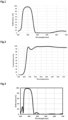
- Fig.1 shows the reflectance curve on the front main face of Lens 1, i.e.: Orma ® substrate coated with IC1 according to Ex.A comprising 10 layers of alternating TiO 2 and SiO 2 .
- This IC1 Ex.A coating has a very strong reflection band between 280 to 240 nm, with a maximum reflectance R max (IC1) of 96% at a wavelength around 370 nm.
- R max IC1
- the Ruv is extremely high, 94.85% at an angle of incidence of 0° and 64.26% at an angle of incidence of 15°.
- the reflection of this coating decreased rapidly down to about 1% at 461 nm.
- the average decreasing rate of reflectance from 90% to 10% in the spectral curve is 2.78%/nm, while the average decreasing rate of reflectance from 80% to 20% in the spectral curve is 3.43%.
- this coating IC1 Ex.A has a low reflection in the visible region, Rv is 0.71% at an angle of incidence of 0° and 0.64% at an angle of incidence of 15°.
- Fig.3 shows the reflectance curve on the front main face of Lens 2, i.e.: Orma ® substrate coated with IC1 according to Ex.B comprising 12 layers of alternating TaOs and SiO 2 .
- This IC1 Ex.B has a very strong reflection band between 280-440 nm, with a maximum reflectance R max (IC1) of 98% at a wavelength around 360 nm.
- R max IC1
- the Ruv is also extremely high, 99.97% at an angle of incidence of 0° and 58.10% at an angle of incidence of 15°.
- the reflection of this coating decreased rapidly down to about 1% at 442 nm.
- the average decreasing rate of reflectance from 90% to 10% in the spectral curve is 2.45%/nm, while the average decreasing rate of reflectance from 80% to 20% in the spectral curve is 2.98%.
- this coating IC1 Ex.B has a low reflection in the visible region, Rv is 0.73% at an angle of incidence of 0° and 0.64% at an angle of incidence of 15°.
- Fig.5 shows the reflectance curve on the front main face of Lens 3, i.e.: Orma ® substrate coated with IC1 according to Ex.C comprising 10 layers of alternating Ti 3 O 5 and SiO 2 .
- This IC1 Ex.C has a very strong reflection band between 280-440 nm, with a maximum reflectance R max (IC1) of 92.70% at a wavelength around 365 nm.
- R max IC1
- the Ruv is also extremely high, 92.21% at an angle of incidence of 0° and 53.11% at an angle of incidence of 15°.
- the reflection of this coating decreased rapidly down to about 7.2% at 438 nm.
- the average decreasing rate of reflectance from 90% to 10% in the spectral curve is 1.62%/nm, while the average decreasing rate of reflectance from 80% to 20% in the spectral curve is 2.15%.
- this coating IC1 Ex.C has a low reflection in the visible region, Rv is 0.76% at an angle of incidence of 0° and 0.64% at an angle of incidence of 15°.
- D.2 Lenses 4 to 6 according to the invention (Fg.2, Fig.4 and Fig.6)
- the table 5 below illustrates the structure and the optical characteristics of Lenses 4 to 6 according to the invention.
- Table 5 Lens 4 Lens 5 Lens 6 Air IC1 Ex.A IC1 Ex.B IC1 Ex.C Substrate coated on its front and back faces with the hard coat HC 1.5 IC2
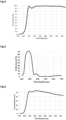
- IC1 Ex.A coating When the IC1 Ex.A coating is applied on the front main face of an ORMA ® substrate providing a standard UV reflection coating (IC2) on its concave main face, a UV cut-off of 380 nm is obtained.
- Fig.2 shows the transmission spectrum of Lens 4.
- the ESPF of lens 4 is about 25 by considering UV transmission from front direction at 0° and total back reflection at 35°.
- IC1 Ex.B coating When the IC1 Ex.B coating is applied on the front main face of an ORMA ® substrate providing a standard UV reflection coating (IC2) on its concave main face, a UV cut-off of 379 nm is obtained.
- Fig.4 shows the transmission spectrum of Lens 5.
- the ESPF of lens 5 is also about 25 by considering UV transmission from front direction at 0° and total back reflection at 35°. In addition, this lens has an excellent blue cut effect.
- IC1 Ex.C coating When the IC1 Ex.C coating is applied on the front main face of an ORMA ® substrate providing a standard UV reflection coating (IC2) on its concave main face, a UV cut-off of 380 nm is obtained.
- Fig.6 shows the transmission spectrum of Lens 6.
- the ESPF of lens 6 is also about 25 by considering UV transmission from front direction at 0° and total back reflection at 35°. In addition, this lens has an excellent blue cut effect.
- optical characteristics of lenses 1 to 6 according to the invention have been compared with lenses according to the prior art and belonging to Essilor International.
- the Applicant has first compared Lenses 4 to 6 according to the invention relative to Ex.1 to 3 of WO 2016 and EX.1 to 3 of WO 2015 that have been also coated on their rear main face with IC2.
- Fig.7 shows the transmittance spectra of these as-coated lenses according to the prior art as compared to Lenses 4 to 6 of the invention. It is noted that the transmittance in the wavelengths ranging from 350 to 380 nm T uv 350-380 (OA) @ 0° of Lenses 4 to 6 of the invention is extremely low, especially as compared to T uv 350-380 (OA) @ 0° of the as-coated lenses according to the prior art comprising the front interferential coating of Ex.1 to EX.3 of WO 2016 and Ex.1 to EX.3 of WO 2015.
- Fig.8 and Table 6 especially show the forward R uv 350-380 as function of the angle of incidence ranging from 0° to 60°.
- the Fig.8 shows that Lenses 1 to 3 of the invention has a R uv 350-380 that is far higher to higher than Ex.1 of WO 2016, Ex.3 of WO 2015 and Ex.3 of WO 2013 and this whatever the angle of incidence. Especially, the forward R uv 350-380 decreases rapidly down to lower than 10% at an angle of incidence of 0°. Therefore, UV protection of WO 2016 is not so high and efficient.
- R uv 350-380 of Ex.3 of WO 2015 and Ex.3 of WO 2013 is similar, i.e.: R uv 350-380 of these two examples is higher than 65% for an angle of incidence ranging from 0° to 60°, with a maximum R uv 350-380 of 78.8% at 30° for Ex.3 of WO 2015 and R uv 350-380 of 78.59% at 35° for Ex.3 of WO 2015.
- Fig.9 and Table 7 show the forward Rv @0° as function of the angle of incidence ranging from 0° to 20°.
- This Fig.9 shows that Lenses 1 to 3 of the invention has a Rv @0° that is far lower to lower than Ex.1 of WO 2016, Ex.3 of WO 2015 and Ex.3 of WO 2013 and this whatever the angle of incidence.
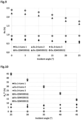
- Fig.10 and Table 8 show the backward Rm B1 @ 35° as function of the angle of incidence ranging from 25° to 50°.
- This Fig.10 shows that Lenses 1 to 3 of the invention has a Rm B1 @ 35° which is far lower than Ex.3 of WO 2015 and Ex.3 of WO 2013 and this whatever the angle of incidence.
- Table 8 ⁇ Lens 1 Lens 2 Lens 3 Ex-2 (WO2016) Ex-3 (WO 2015) Ex-3 (WO 2013)
- Backward R m B1 (%) 30° 5,85 5,42 7,83 0,15 37,17 38,27 35° 6,97 4,00 7,74 0,26 29,22 30,26 40° 7,94 4,28 7,88 0,44 21,16 22,08 45° 8,47 5,21 7,97 0,75 13,86 14,59
Landscapes
- Physics & Mathematics (AREA)
- General Physics & Mathematics (AREA)
- Optics & Photonics (AREA)
- Chemical & Material Sciences (AREA)
- Inorganic Chemistry (AREA)
- Eyeglasses (AREA)
Priority Applications (2)
| Application Number | Priority Date | Filing Date | Title |
|---|---|---|---|
| EP23306584.6A EP4528340A1 (de) | 2023-09-22 | 2023-09-22 | Optischer artikel mit einer sehr hochreflektierenden beschichtung im band-35-380 uv |
| PCT/EP2024/076325 WO2025061879A1 (en) | 2023-09-22 | 2024-09-19 | Optical article having a very high reflective coating in the 350-380 uv band |
Applications Claiming Priority (1)
| Application Number | Priority Date | Filing Date | Title |
|---|---|---|---|
| EP23306584.6A EP4528340A1 (de) | 2023-09-22 | 2023-09-22 | Optischer artikel mit einer sehr hochreflektierenden beschichtung im band-35-380 uv |
Publications (1)
| Publication Number | Publication Date |
|---|---|
| EP4528340A1 true EP4528340A1 (de) | 2025-03-26 |
Family
ID=88315602
Family Applications (1)
| Application Number | Title | Priority Date | Filing Date |
|---|---|---|---|
| EP23306584.6A Pending EP4528340A1 (de) | 2023-09-22 | 2023-09-22 | Optischer artikel mit einer sehr hochreflektierenden beschichtung im band-35-380 uv |
Country Status (2)
| Country | Link |
|---|---|
| EP (1) | EP4528340A1 (de) |
| WO (1) | WO2025061879A1 (de) |
Citations (26)
| Publication number | Priority date | Publication date | Assignee | Title |
|---|---|---|---|---|
| US639A (en) | 1838-03-17 | of boston | ||
| US872A (en) | 1838-08-03 | Hand-bellows | ||
| US5739A (en) | 1848-08-29 | William easby | ||
| US6183A (en) | 1849-03-13 | Improvement in grain-gatherers | ||
| US4211823A (en) | 1977-03-11 | 1980-07-08 | Toray Industries, Inc. | Tintable coatings and articles having such coatings |
| JPS6387223A (ja) | 1986-09-30 | 1988-04-18 | Hoya Corp | プラスチックレンズ |
| JPS63141001A (ja) | 1986-12-04 | 1988-06-13 | Hoya Corp | プラスチツクレンズの製造法 |
| EP0404111A2 (de) | 1989-06-20 | 1990-12-27 | Nippon Sheet Glass Co. Ltd. | Verfahren zur Herstellung einer Kunststofflinse |
| US5015523A (en) | 1983-07-29 | 1991-05-14 | Seiko Epson Corporation | Coated synthetic resin lens |
| US5081192A (en) | 1988-05-21 | 1992-01-14 | Daikin Industries Ltd. | Novel polymer and its preparation and use |
| US5316791A (en) | 1993-01-21 | 1994-05-31 | Sdc Coatings Inc. | Process for improving impact resistance of coated plastic substrates |
| US5332618A (en) * | 1992-02-07 | 1994-07-26 | Tru Vue, Inc. | Antireflection layer system with integral UV blocking properties |
| EP0614957A1 (de) | 1993-03-08 | 1994-09-14 | ESSILOR INTERNATIONAL Compagnie Générale d'Optique | Abriebfeste Beschichtungszusammensetzungen auf Basis von hydrolysierte Silane und Aluminiumverbindungen; abriebfeste und schlagzühe Gegenstände |
| US5763061A (en) | 1995-06-15 | 1998-06-09 | Sumitomo Chemical Company, Limited | Antireflection filter |
| US5922787A (en) | 1996-03-21 | 1999-07-13 | Sony Corporation | Composition for forming antifouling antifouling film, optical component, and display device |
| EP0933377A2 (de) | 1998-01-31 | 1999-08-04 | Toppan Printing Co., Ltd. | Antischmier-Mittel, Verfahren zur Herstellung einer Antischmier-Schicht, optisches Bauteil mit Antireflexions Eigenschaften und Anzeigevorrichtung |
| US6277485B1 (en) | 1998-01-27 | 2001-08-21 | 3M Innovative Properties Company | Antisoiling coatings for antireflective surfaces and methods of preparation |
| US6337235B1 (en) | 1999-03-26 | 2002-01-08 | Semiconductor Energy Laboratory Co., Ltd. | Semiconductor device and manufacturing method thereof |
| EP1392613A1 (de) | 2001-05-17 | 2004-03-03 | Essilor International Compagnie Generale D'optique | Verfahren zur herstellung von randbearbeitungfähigem glas, hergestelltes glas und verfahren zur randbearbeitung von einem solchen glas |
| EP1467955A1 (de) | 2002-01-14 | 2004-10-20 | Essilor International Compagnie Generale D'optique | Verfahren zur behandlung einer ophthalmischen linse |
| EP1633684A1 (de) | 2003-06-13 | 2006-03-15 | ESSILOR INTERNATIONAL (Compagnie Générale d'Optique) | Verfahren zur behandlung einer trimmbaren linse |
| EP2122392A1 (de) | 2007-02-23 | 2009-11-25 | Essilor International (Compagnie Générale D'Optique) | Prozess zur herstellung eines mit einer antireflex- oder reflektierenden beschichtung beschichteten optischen artikels mit verbesserten adhäsions- und abrasionsbeständigkeitseigenschaften |
| WO2012076714A1 (en) | 2010-12-10 | 2012-06-14 | Essilor International (Compagnie Generale D'optique) | Optical article comprising an antireflective coating with a low reflection both in the ultraviolet region and in the visible region |
| WO2013171434A1 (fr) | 2012-05-16 | 2013-11-21 | Essilor International (Compagnie Generale D'optique) | Lentille ophtalmique |
| WO2015040184A1 (en) | 2013-09-20 | 2015-03-26 | Essilor International (Compagnie Generale D'optique) | Optical article with gradient photochromism |
| WO2016102857A1 (fr) | 2014-12-24 | 2016-06-30 | Essilor International (Compagnie Générale d'Optique) | Article optique comportant un revêtement interférentiel à forte réflexion dans le domaine de l'ultraviolet |
-
2023
- 2023-09-22 EP EP23306584.6A patent/EP4528340A1/de active Pending
-
2024
- 2024-09-19 WO PCT/EP2024/076325 patent/WO2025061879A1/en active Pending
Patent Citations (30)
| Publication number | Priority date | Publication date | Assignee | Title |
|---|---|---|---|---|
| US872A (en) | 1838-08-03 | Hand-bellows | ||
| US5739A (en) | 1848-08-29 | William easby | ||
| US6183A (en) | 1849-03-13 | Improvement in grain-gatherers | ||
| US639A (en) | 1838-03-17 | of boston | ||
| US4211823A (en) | 1977-03-11 | 1980-07-08 | Toray Industries, Inc. | Tintable coatings and articles having such coatings |
| US5015523A (en) | 1983-07-29 | 1991-05-14 | Seiko Epson Corporation | Coated synthetic resin lens |
| JPS6387223A (ja) | 1986-09-30 | 1988-04-18 | Hoya Corp | プラスチックレンズ |
| JPS63141001A (ja) | 1986-12-04 | 1988-06-13 | Hoya Corp | プラスチツクレンズの製造法 |
| US5081192A (en) | 1988-05-21 | 1992-01-14 | Daikin Industries Ltd. | Novel polymer and its preparation and use |
| EP0404111A2 (de) | 1989-06-20 | 1990-12-27 | Nippon Sheet Glass Co. Ltd. | Verfahren zur Herstellung einer Kunststofflinse |
| US5332618A (en) * | 1992-02-07 | 1994-07-26 | Tru Vue, Inc. | Antireflection layer system with integral UV blocking properties |
| EP0680492A1 (de) | 1993-01-21 | 1995-11-08 | Sdc Coatings Inc | Verfahren zur schlagfestigkeitssteigerung von beschichtetn kunststoffsubstraten. |
| US5316791A (en) | 1993-01-21 | 1994-05-31 | Sdc Coatings Inc. | Process for improving impact resistance of coated plastic substrates |
| EP0614957A1 (de) | 1993-03-08 | 1994-09-14 | ESSILOR INTERNATIONAL Compagnie Générale d'Optique | Abriebfeste Beschichtungszusammensetzungen auf Basis von hydrolysierte Silane und Aluminiumverbindungen; abriebfeste und schlagzühe Gegenstände |
| FR2702486A1 (fr) | 1993-03-08 | 1994-09-16 | Essilor Int | Compositions de revêtement antiabrasion à base d'hydrolysats de silanes et de composés de l'aluminium, et articles revêtus correspondants résistants à l'abrasion et aux chocs. |
| US5763061A (en) | 1995-06-15 | 1998-06-09 | Sumitomo Chemical Company, Limited | Antireflection filter |
| US5922787A (en) | 1996-03-21 | 1999-07-13 | Sony Corporation | Composition for forming antifouling antifouling film, optical component, and display device |
| US6277485B1 (en) | 1998-01-27 | 2001-08-21 | 3M Innovative Properties Company | Antisoiling coatings for antireflective surfaces and methods of preparation |
| EP0933377A2 (de) | 1998-01-31 | 1999-08-04 | Toppan Printing Co., Ltd. | Antischmier-Mittel, Verfahren zur Herstellung einer Antischmier-Schicht, optisches Bauteil mit Antireflexions Eigenschaften und Anzeigevorrichtung |
| US6337235B1 (en) | 1999-03-26 | 2002-01-08 | Semiconductor Energy Laboratory Co., Ltd. | Semiconductor device and manufacturing method thereof |
| EP1392613A1 (de) | 2001-05-17 | 2004-03-03 | Essilor International Compagnie Generale D'optique | Verfahren zur herstellung von randbearbeitungfähigem glas, hergestelltes glas und verfahren zur randbearbeitung von einem solchen glas |
| EP1467955A1 (de) | 2002-01-14 | 2004-10-20 | Essilor International Compagnie Generale D'optique | Verfahren zur behandlung einer ophthalmischen linse |
| EP1633684A1 (de) | 2003-06-13 | 2006-03-15 | ESSILOR INTERNATIONAL (Compagnie Générale d'Optique) | Verfahren zur behandlung einer trimmbaren linse |
| EP2122392A1 (de) | 2007-02-23 | 2009-11-25 | Essilor International (Compagnie Générale D'Optique) | Prozess zur herstellung eines mit einer antireflex- oder reflektierenden beschichtung beschichteten optischen artikels mit verbesserten adhäsions- und abrasionsbeständigkeitseigenschaften |
| WO2012076714A1 (en) | 2010-12-10 | 2012-06-14 | Essilor International (Compagnie Generale D'optique) | Optical article comprising an antireflective coating with a low reflection both in the ultraviolet region and in the visible region |
| FR2968774A1 (fr) | 2010-12-10 | 2012-06-15 | Essilor Int | Article d'optique comportant un revetement antireflet a faible reflexion dans le domaine ultraviolet et le domaine visible |
| WO2013171434A1 (fr) | 2012-05-16 | 2013-11-21 | Essilor International (Compagnie Generale D'optique) | Lentille ophtalmique |
| WO2015040184A1 (en) | 2013-09-20 | 2015-03-26 | Essilor International (Compagnie Generale D'optique) | Optical article with gradient photochromism |
| WO2016102857A1 (fr) | 2014-12-24 | 2016-06-30 | Essilor International (Compagnie Générale d'Optique) | Article optique comportant un revêtement interférentiel à forte réflexion dans le domaine de l'ultraviolet |
| US20170351119A1 (en) * | 2014-12-24 | 2017-12-07 | Essilor International (Compagnie-Generale D'optique) | Optical article comprising an interference coating with high reflectivity in the ultraviolet region |
Non-Patent Citations (1)
| Title |
|---|
| "Thin Film Processes", 1978, ACADEMIC PRESS, article "Thin Film Processes II" |
Also Published As
| Publication number | Publication date |
|---|---|
| WO2025061879A1 (en) | 2025-03-27 |
Similar Documents
| Publication | Publication Date | Title |
|---|---|---|
| JP7266510B2 (ja) | 紫外領域及び可視領域の両方において低い反射性を持つ反射防止膜を有する光学部品 | |
| CN105359005B (zh) | 包括在可见光区具有极低反射的抗反射涂层的光学制品 | |
| EP3497489B1 (de) | Optischer artikel mit einer interferenzbeschichtung mit einer hohen reflexion im nahen infrarotbereich (nir) | |
| US10288905B2 (en) | Optical article comprising an interference coating with high reflectivity in the ultraviolet region | |
| EP3268776B1 (de) | Brillenlinse mit antireflexbeschichtung im sichtbaren bereich für niedrige luminanzbedingungen | |
| KR102835324B1 (ko) | 내마모성을 개선하기 위한 필터링 간섭 코팅 및 다층 시스템을 갖는 광학 렌즈 | |
| US11397285B2 (en) | Optical article having an abrasion and temperature resistant interferential coating with an optimized thickness ratio of low and high refractive index layers | |
| US10877183B2 (en) | Optical article comprising an antireflective coating with a high reflection in the near infrared region (NIR) | |
| US12135407B2 (en) | Optical lens having an enhanced interferential coating and a multilayer system for improving abrasion-resistance | |
| US20230176255A1 (en) | Optical article with very low reflection in the visible region and in the near infrared region | |
| US20250060514A1 (en) | Optical lens having a mirror coating and a multilayer system for improving abrasion-resistance | |
| EP4528340A1 (de) | Optischer artikel mit einer sehr hochreflektierenden beschichtung im band-35-380 uv | |
| EP4571371A1 (de) | Optischer artikel mit interferenzieller beschichtung mit farbrobustheit |
Legal Events
| Date | Code | Title | Description |
|---|---|---|---|
| PUAI | Public reference made under article 153(3) epc to a published international application that has entered the european phase |
Free format text: ORIGINAL CODE: 0009012 |
|
| STAA | Information on the status of an ep patent application or granted ep patent |
Free format text: STATUS: THE APPLICATION HAS BEEN PUBLISHED |
|
| AK | Designated contracting states |
Kind code of ref document: A1 Designated state(s): AL AT BE BG CH CY CZ DE DK EE ES FI FR GB GR HR HU IE IS IT LI LT LU LV MC ME MK MT NL NO PL PT RO RS SE SI SK SM TR |
|
| STAA | Information on the status of an ep patent application or granted ep patent |
Free format text: STATUS: REQUEST FOR EXAMINATION WAS MADE |
|
| 17P | Request for examination filed |
Effective date: 20250827 |