EP4528154A1 - Atmosphere lamp - Google Patents
Atmosphere lamp Download PDFInfo
- Publication number
- EP4528154A1 EP4528154A1 EP23834740.5A EP23834740A EP4528154A1 EP 4528154 A1 EP4528154 A1 EP 4528154A1 EP 23834740 A EP23834740 A EP 23834740A EP 4528154 A1 EP4528154 A1 EP 4528154A1
- Authority
- EP
- European Patent Office
- Prior art keywords
- circuit board
- light guide
- auxiliary circuit
- guide block
- atmosphere lamp
- Prior art date
- Legal status (The legal status is an assumption and is not a legal conclusion. Google has not performed a legal analysis and makes no representation as to the accuracy of the status listed.)
- Pending
Links
Images



Classifications
-
- F—MECHANICAL ENGINEERING; LIGHTING; HEATING; WEAPONS; BLASTING
- F21—LIGHTING
- F21V—FUNCTIONAL FEATURES OR DETAILS OF LIGHTING DEVICES OR SYSTEMS THEREOF; STRUCTURAL COMBINATIONS OF LIGHTING DEVICES WITH OTHER ARTICLES, NOT OTHERWISE PROVIDED FOR
- F21V17/00—Fastening of component parts of lighting devices, e.g. shades, globes, refractors, reflectors, filters, screens, grids or protective cages
- F21V17/10—Fastening of component parts of lighting devices, e.g. shades, globes, refractors, reflectors, filters, screens, grids or protective cages characterised by specific fastening means or way of fastening
- F21V17/16—Fastening of component parts of lighting devices, e.g. shades, globes, refractors, reflectors, filters, screens, grids or protective cages characterised by specific fastening means or way of fastening by deformation of parts; Snap action mounting
- F21V17/164—Fastening of component parts of lighting devices, e.g. shades, globes, refractors, reflectors, filters, screens, grids or protective cages characterised by specific fastening means or way of fastening by deformation of parts; Snap action mounting the parts being subjected to bending, e.g. snap joints
-
- B—PERFORMING OPERATIONS; TRANSPORTING
- B60—VEHICLES IN GENERAL
- B60Q—ARRANGEMENT OF SIGNALLING OR LIGHTING DEVICES, THE MOUNTING OR SUPPORTING THEREOF OR CIRCUITS THEREFOR, FOR VEHICLES IN GENERAL
- B60Q3/00—Arrangement of lighting devices for vehicle interiors; Lighting devices specially adapted for vehicle interiors
- B60Q3/20—Arrangement of lighting devices for vehicle interiors; Lighting devices specially adapted for vehicle interiors for lighting specific fittings of passenger or driving compartments; mounted on specific fittings of passenger or driving compartments
- B60Q3/208—Sun roofs; Windows
-
- F—MECHANICAL ENGINEERING; LIGHTING; HEATING; WEAPONS; BLASTING
- F21—LIGHTING
- F21K—NON-ELECTRIC LIGHT SOURCES USING LUMINESCENCE; LIGHT SOURCES USING ELECTROCHEMILUMINESCENCE; LIGHT SOURCES USING CHARGES OF COMBUSTIBLE MATERIAL; LIGHT SOURCES USING SEMICONDUCTOR DEVICES AS LIGHT-GENERATING ELEMENTS; LIGHT SOURCES NOT OTHERWISE PROVIDED FOR
- F21K9/00—Light sources using semiconductor devices as light-generating elements, e.g. using light-emitting diodes [LED] or lasers
- F21K9/20—Light sources comprising attachment means
- F21K9/23—Retrofit light sources for lighting devices with a single fitting for each light source, e.g. for substitution of incandescent lamps with bayonet or threaded fittings
- F21K9/238—Arrangement or mounting of circuit elements integrated in the light source
-
- F—MECHANICAL ENGINEERING; LIGHTING; HEATING; WEAPONS; BLASTING
- F21—LIGHTING
- F21K—NON-ELECTRIC LIGHT SOURCES USING LUMINESCENCE; LIGHT SOURCES USING ELECTROCHEMILUMINESCENCE; LIGHT SOURCES USING CHARGES OF COMBUSTIBLE MATERIAL; LIGHT SOURCES USING SEMICONDUCTOR DEVICES AS LIGHT-GENERATING ELEMENTS; LIGHT SOURCES NOT OTHERWISE PROVIDED FOR
- F21K9/00—Light sources using semiconductor devices as light-generating elements, e.g. using light-emitting diodes [LED] or lasers
- F21K9/60—Optical arrangements integrated in the light source, e.g. for improving the colour rendering index or the light extraction
- F21K9/61—Optical arrangements integrated in the light source, e.g. for improving the colour rendering index or the light extraction using light guides
-
- F—MECHANICAL ENGINEERING; LIGHTING; HEATING; WEAPONS; BLASTING
- F21—LIGHTING
- F21V—FUNCTIONAL FEATURES OR DETAILS OF LIGHTING DEVICES OR SYSTEMS THEREOF; STRUCTURAL COMBINATIONS OF LIGHTING DEVICES WITH OTHER ARTICLES, NOT OTHERWISE PROVIDED FOR
- F21V19/00—Fastening of light sources or lamp holders
- F21V19/001—Fastening of light sources or lamp holders the light sources being semiconductors devices, e.g. LEDs
- F21V19/003—Fastening of light source holders, e.g. of circuit boards or substrates holding light sources
- F21V19/0035—Fastening of light source holders, e.g. of circuit boards or substrates holding light sources the fastening means being capable of simultaneously attaching of an other part, e.g. a housing portion or an optical component
-
- F—MECHANICAL ENGINEERING; LIGHTING; HEATING; WEAPONS; BLASTING
- F21—LIGHTING
- F21V—FUNCTIONAL FEATURES OR DETAILS OF LIGHTING DEVICES OR SYSTEMS THEREOF; STRUCTURAL COMBINATIONS OF LIGHTING DEVICES WITH OTHER ARTICLES, NOT OTHERWISE PROVIDED FOR
- F21V23/00—Arrangement of electric circuit elements in or on lighting devices
- F21V23/003—Arrangement of electric circuit elements in or on lighting devices the elements being electronics drivers or controllers for operating the light source, e.g. for a LED array
- F21V23/004—Arrangement of electric circuit elements in or on lighting devices the elements being electronics drivers or controllers for operating the light source, e.g. for a LED array arranged on a substrate, e.g. a printed circuit board
- F21V23/005—Arrangement of electric circuit elements in or on lighting devices the elements being electronics drivers or controllers for operating the light source, e.g. for a LED array arranged on a substrate, e.g. a printed circuit board the substrate is supporting also the light source
-
- F—MECHANICAL ENGINEERING; LIGHTING; HEATING; WEAPONS; BLASTING
- F21—LIGHTING
- F21V—FUNCTIONAL FEATURES OR DETAILS OF LIGHTING DEVICES OR SYSTEMS THEREOF; STRUCTURAL COMBINATIONS OF LIGHTING DEVICES WITH OTHER ARTICLES, NOT OTHERWISE PROVIDED FOR
- F21V33/00—Structural combinations of lighting devices with other articles, not otherwise provided for
-
- B—PERFORMING OPERATIONS; TRANSPORTING
- B60—VEHICLES IN GENERAL
- B60Q—ARRANGEMENT OF SIGNALLING OR LIGHTING DEVICES, THE MOUNTING OR SUPPORTING THEREOF OR CIRCUITS THEREFOR, FOR VEHICLES IN GENERAL
- B60Q3/00—Arrangement of lighting devices for vehicle interiors; Lighting devices specially adapted for vehicle interiors
- B60Q3/60—Arrangement of lighting devices for vehicle interiors; Lighting devices specially adapted for vehicle interiors characterised by optical aspects
- B60Q3/62—Arrangement of lighting devices for vehicle interiors; Lighting devices specially adapted for vehicle interiors characterised by optical aspects using light guides
- B60Q3/64—Arrangement of lighting devices for vehicle interiors; Lighting devices specially adapted for vehicle interiors characterised by optical aspects using light guides for a single lighting device
-
- F—MECHANICAL ENGINEERING; LIGHTING; HEATING; WEAPONS; BLASTING
- F21—LIGHTING
- F21S—NON-PORTABLE LIGHTING DEVICES; SYSTEMS THEREOF; VEHICLE LIGHTING DEVICES SPECIALLY ADAPTED FOR VEHICLE EXTERIORS
- F21S4/00—Lighting devices or systems using a string or strip of light sources
- F21S4/20—Lighting devices or systems using a string or strip of light sources with light sources held by or within elongate supports
-
- F—MECHANICAL ENGINEERING; LIGHTING; HEATING; WEAPONS; BLASTING
- F21—LIGHTING
- F21S—NON-PORTABLE LIGHTING DEVICES; SYSTEMS THEREOF; VEHICLE LIGHTING DEVICES SPECIALLY ADAPTED FOR VEHICLE EXTERIORS
- F21S43/00—Signalling devices specially adapted for vehicle exteriors, e.g. brake lamps, direction indicator lights or reversing lights
- F21S43/20—Signalling devices specially adapted for vehicle exteriors, e.g. brake lamps, direction indicator lights or reversing lights characterised by refractors, transparent cover plates, light guides or filters
- F21S43/27—Attachment thereof
-
- F—MECHANICAL ENGINEERING; LIGHTING; HEATING; WEAPONS; BLASTING
- F21—LIGHTING
- F21V—FUNCTIONAL FEATURES OR DETAILS OF LIGHTING DEVICES OR SYSTEMS THEREOF; STRUCTURAL COMBINATIONS OF LIGHTING DEVICES WITH OTHER ARTICLES, NOT OTHERWISE PROVIDED FOR
- F21V2200/00—Use of light guides, e.g. fibre optic devices, in lighting devices or systems
-
- F—MECHANICAL ENGINEERING; LIGHTING; HEATING; WEAPONS; BLASTING
- F21—LIGHTING
- F21Y—INDEXING SCHEME ASSOCIATED WITH SUBCLASSES F21K, F21L, F21S and F21V, RELATING TO THE FORM OR THE KIND OF THE LIGHT SOURCES OR OF THE COLOUR OF THE LIGHT EMITTED
- F21Y2103/00—Elongate light sources, e.g. fluorescent tubes
- F21Y2103/10—Elongate light sources, e.g. fluorescent tubes comprising a linear array of point-like light-generating elements
-
- F—MECHANICAL ENGINEERING; LIGHTING; HEATING; WEAPONS; BLASTING
- F21—LIGHTING
- F21Y—INDEXING SCHEME ASSOCIATED WITH SUBCLASSES F21K, F21L, F21S and F21V, RELATING TO THE FORM OR THE KIND OF THE LIGHT SOURCES OR OF THE COLOUR OF THE LIGHT EMITTED
- F21Y2115/00—Light-generating elements of semiconductor light sources
- F21Y2115/10—Light-emitting diodes [LED]
-
- G—PHYSICS
- G02—OPTICS
- G02B—OPTICAL ELEMENTS, SYSTEMS OR APPARATUS
- G02B6/00—Light guides; Structural details of arrangements comprising light guides and other optical elements, e.g. couplings
- G02B6/0001—Light guides; Structural details of arrangements comprising light guides and other optical elements, e.g. couplings specially adapted for lighting devices or systems
- G02B6/0011—Light guides; Structural details of arrangements comprising light guides and other optical elements, e.g. couplings specially adapted for lighting devices or systems the light guides being planar or of plate-like form
- G02B6/0013—Means for improving the coupling-in of light from the light source into the light guide
- G02B6/0015—Means for improving the coupling-in of light from the light source into the light guide provided on the surface of the light guide or in the bulk of it
- G02B6/002—Means for improving the coupling-in of light from the light source into the light guide provided on the surface of the light guide or in the bulk of it by shaping at least a portion of the light guide, e.g. with collimating, focussing or diverging surfaces
- G02B6/0021—Means for improving the coupling-in of light from the light source into the light guide provided on the surface of the light guide or in the bulk of it by shaping at least a portion of the light guide, e.g. with collimating, focussing or diverging surfaces for housing at least a part of the light source, e.g. by forming holes or recesses
Definitions
- the present disclosure relates to the technical field of light emitting devices, and particularly to an atmosphere lamp.
- the atmosphere lamp is a light emitting device that uses a light source combined with a circuit board to control the changes of different brightnesses, gray scales and colors.
- the atmosphere lamp can be mounted on various occasions, such as vehicles and buildings, and has a wide application range.
- the light rays generated by the light source on the circuit board are guided to be emitted in a specific direction through a light guide block.
- the light guide block is mounted on the circuit board by means of hot-riveting, that is, a rivet stud is disposed on the light guide block, a mounting hole is formed in the circuit board, and an end of the rivet stud passes through the mounting hole and is heated to form a rivet head, so that the light guide block is fixed on the circuit board.
- a corresponding hot-riveting tool needs to be separately disposed and matched with a hot-riveting device, resulting in high cost, complicated procedures, and low assembly efficiency.
- the present disclosure aims to provide an atmosphere lamp, so as to solve the technical problems of high cost, complicated procedures and low assembly efficiency that are caused by the fact that a light guide block needs to be mounted on a circuit board by means of hot-riveting when the atmosphere lamp is assembled.
- the above object of the present disclosure can be achieved using the following technical solutions:
- the present disclosure provides an atmosphere lamp, comprising: at least one main circuit board; at least one auxiliary circuit board mounted on and electrically connected to the main circuit board, the auxiliary circuit board being provided with at least one light source structure; and at least one light guide block provided with at least one snapping groove, the light guide block being snapped onto the auxiliary circuit board by means of the snapping groove, and the light guide block being provided with at least one light incident surface disposed opposite to the light source structure.
- the present disclosure has the following characteristics and advantages:
- at least one snapping groove matched with the auxiliary circuit board is formed in the light guide block, so that the light guide block can be directly snapped onto the auxiliary circuit board, and the light incident surface of the light guide block can be corresponding to the light source structure on the auxiliary circuit board, thereby utilizing the light guide block to guide light rays generated by the light source structure to be emitted according to a specific path.
- the atmosphere lamp has a simple structure, does not need other tools for snapping and positioning, and also does not need machining a rivet stud on the light guide block and forming a hole in the auxiliary circuit board to perform hot-riveting, thereby achieving a high assembling efficiency and a low cost.
- 1 main circuit board; 11: mounting groove; 2: auxiliary circuit board; 21: mounting block; 22: welding pin; 23: light source structure; 24: first groove; 25: second groove; 26: third groove; 27: fourth groove; 3: light guide block; 31: light incident surface; 4: snapping groove; 41: claw; 42: first bump; 5: transverse limiting structure; 51: transverse limiting groove; 52: transverse limiting block; 53: connecting plate; 6: longitudinal limiting structure; 61: longitudinal limiting groove; 62: longitudinal limiting block; 621: guide slope; 622: limiting slope; 7: support structure; 71: second bump; 8: connector.
- the present disclosure provides an atmosphere lamp, which includes at least one main circuit board 1, at least one auxiliary circuit board 2 mounted on and electrically connected to the main circuit board 1, and at least one light guide block 3 provided with at least one snapping groove 4.
- the auxiliary circuit board 2 is provided with at least one light source structure 23.
- the light guide block 3 is snapped onto the auxiliary circuit board 2 through the snapping groove 4.
- the light guide block 3 is provided with at least one light incident surface 31 disposed opposite to the light source structure 23.
- the light guide block 3 is provided with at least one snapping groove 4 matched with the auxiliary circuit board 2, so that the light guide block 3 can be directly snapped onto the auxiliary circuit board 2, with the light incident surface 31 of the light guide block 3 being corresponding to the light source structure 23 on the auxiliary circuit board 2, thereby utilizing the light guide block 3 to guide light rays generated by the light source structure 23 to be emitted along a specific path.
- the atmosphere lamp is simple in structure, does not need other tools for snapping and positioning, and also does not need machining a rivet stud on the light guide block 3 and forming a hole in the auxiliary circuit board 2 for hot riveting, thereby achieving high assembling efficiency and low cost.
- a width of the snapping groove 4 is slightly smaller than a thickness of the auxiliary circuit board 2.
- the light source structure 23 includes a plurality of LED particles.
- the light guide block 3 receives, through a light incident surface 31 thereof, light rays generated by the plurality of LED particles, and the light rays are diffusely reflected by the light guide block 3 and then transferred to the glass of the atmosphere lamp or any other light-transmitting part along a specific path. As illustrated in FIGS.
- the main circuit board 1 is provided with a mounting groove 11
- the auxiliary circuit board 2 is provided with a mounting block 21 inserted into the mounting groove 11
- the auxiliary circuit board 2 is welded to and fixed on the main circuit board 1 through a plurality of welding pins 22 and is electrically connected to the main circuit board 1.
- Either of the main circuit board 1 and auxiliary circuit board 2 is a PCBA board.
- the light guide block 3 is provided with at least one claw 41 and at least one first bump 42, the first bump 42 and the light incident surface 31 are located on the same side of the light guide block 3, and the claw 41 and the first bump 42 are cooperated to form the snapping groove 4.
- the first bump 42 By disposing the first bump 42, a space for mounting the light source structure 23 is available between the light incident surface 31 and the auxiliary circuit board 2.
- the light guide block 3 is ensured to be snapped and fixed on the auxiliary circuit board 2, and the light guide block 3 and the auxiliary circuit board 2 do not move relative to each other in a width direction of the snapping groove 4, i.e., a width direction X of the auxiliary circuit board 2 and the light guide block 3.
- the claw 41, the first bump 42, and the light guide block 3 are integrally formed for easy processing.
- the light guide block 3 is provided with a light incident side surface opposite to the auxiliary circuit board 2, and a top surface away from the main circuit board 1 and connected to the side surface. Both the light incident surface 31 and the first bump 42 are located on the light incident side surface of the light guide block 3. A fixed end of the claw 41 is connected to the top surface of the light guide block 3.
- the claw 41 is substantially L-shaped.
- a transverse limiting structure 5 is disposed between the light guide block 3 and the auxiliary circuit board 2 to limit a relative movement between the light guide block 3 and the auxiliary circuit board 2 in a length direction of the snapping groove 4, which is an axial direction of the snapping groove 4 and is also a length direction Y of the auxiliary circuit board 2 and the light guide block 3.
- the transverse limiting structure 5 includes a transverse limiting block 52 and a transverse limiting groove 51, and the transverse limiting block 52 is disposed on the auxiliary circuit board 2 and matched with the transverse limiting groove 51.
- the light guide block 3 includes a plurality of claws 41.
- the plurality of claws 41 and the plurality of first bumps 42 are cooperated to form a plurality of snapping grooves 4, and the light guide block 3 is snapped onto the auxiliary circuit board 2 through the plurality of snapping grooves 4, so that the light guide block 3 can be mounted more stably.
- two claws 41 are disposed at an interval along the length direction of the auxiliary circuit board 2.
- the transverse limiting groove 51 is formed between two adjacent claws 41, which is simple in structure and easy to process. Specifically, the top surface of the auxiliary circuit board 2 is cut to form a first groove 24 and a second groove 25, so that the transverse stop block 52 is formed between the first groove 24 and the second groove 25, and the two claws 41 are mounted in the first groove 24 and the second groove 25.
- adjacent two of the claws 41 are connected through a connecting plate 53 in which the transverse limiting groove 51 is formed.
- the connection of the adjacent two of the claws 41 through the connecting plate 53 can also make the structure of the two claws 41 more stable.
- the connecting plate 53 is connected to the top surface of the light guide block 3.
- the top surface of the auxiliary circuit board 2 is cut to form a third groove 26 and a fourth groove 27, so that the transverse limiting block 52 is formed between the third groove 26 and the fourth groove 27, and the two claws 41 are mounted in the third groove 26 and the fourth groove 27.
- the light guide block 3 is an asymmetric structure with respect to a center of the transverse limiting groove 51.
- the auxiliary circuit board 2 is an asymmetric structure with respect to the center of the transverse limiting block 52.
- the first groove 24 is a stepped groove
- the second groove 25 is a three-sided open groove, so that the auxiliary circuit board 2 forms an asymmetric structure.
- the two claws 41 are disposed asymmetrically with respect to a center of the light guide block 3, so that the light guide block 3 forms an asymmetric structure.
- the transverse limiting groove 51 is disposed close to one of the claws 41, so that the light guide block 3 forms an asymmetric structure.
- the third groove 26 and the fourth groove 27 are both stepped grooves, but an extension dimension of the third groove 26 in the length direction Y of the auxiliary circuit board 2 is greater than an extension dimension of the fourth groove 27 in the length direction Y of the auxiliary circuit board 2, so that the auxiliary circuit board 2 forms an asymmetric structure.
- a longitudinal limiting structure 6 is disposed between the light guide block 3 and the auxiliary circuit board 2 to limit the auxiliary circuit board 2 from falling out of the snapping groove 4.
- the longitudinal limiting structure 6 includes a longitudinal limiting block 62 and a longitudinal limiting groove 61
- the claw 41 has an inner side surface opposite to the auxiliary circuit board 2
- the longitudinal limiting block 62 is disposed on the inner side surface of the claw 41
- the longitudinal limiting groove 61 is disposed on the auxiliary circuit board 2 and matched with the longitudinal limiting block 62.
- the longitudinal limiting block 62 is provided with a guide slope 621 which is inclined towards the outside of the snapping groove 4 along a mounting direction of the light guide block 3 (i.e., downward along the direction Z).
- the auxiliary circuit board 2 is guided by the guide slope 621 to pass through the longitudinal limiting block 62 to be snapped into the snapping groove 4, so that the longitudinal limiting block 62 is snapped into the longitudinal limiting groove 61 on the auxiliary circuit board 2.
- the longitudinal limiting block 62 is further provided with a limiting slope 622, which is inclined towards the inside of the longitudinal limiting groove 61 along a snapping direction of the longitudinal limiting block 62.
- the longitudinal limiting block 62 is snapped into the longitudinal limiting groove 61 along the thickness direction of the auxiliary circuit board 2.
- a support structure 7 is disposed on the light guide block 3, and abuts against the main circuit board 1 along the mounting direction of the light guide block 3. Since the light guide block 3 is supported by the main circuit board 1, the mounting stability of the light guide block 3 is improved and the light guide block 3 is prevented from being turned over.
- the support structure 7 includes a plurality of second bumps 71 disposed symmetrically with respect to the center of gravity of the light guide block 3.
- the support structure 7 includes two second bumps 71 each being a substantially cylindrical structure.
- the second bumps 71 are integrally formed on a bottom surface of the light guide block 3 opposite to the main circuit board 1.
- a layout angle between the auxiliary circuit board 2 and the main circuit board 1 is not particularly limited, and as illustrated in FIGS. 1 and 7 , in the embodiment of the present disclosure, the auxiliary circuit board 2 has a first end and a second end opposite to each other, the first end of the auxiliary circuit board 2 is connected to the main circuit board 1 and disposed vertically, and the light guide block 3 is snapped onto the auxiliary circuit board 2 from the second end of the auxiliary circuit board 2 through the snapping groove 4, so that the auxiliary circuit board 2 can be more stably mounted on the main circuit board 1, and the auxiliary circuit board 2 is less likely to interfere with other electronic components on the main circuit board 1.
- the atmosphere lamp includes a plurality of main circuit boards 1, a plurality of auxiliary circuit boards 2 and a plurality of light guide blocks 3; the plurality of main circuit boards 1 are connected and conducted through a connector 8, the plurality of auxiliary circuit boards 2 are mounted on the plurality of main circuit boards 1 in one-to-one correspondence, and the plurality of light guide blocks 3 are mounted on the plurality of auxiliary circuit boards 2 in one-to-one correspondence.
- the plurality of auxiliary circuit boards 2 are mounted on the same main circuit board 1.
- the plurality of light guide blocks 3 are mounted on the plurality of auxiliary circuit boards 2 in one-to-one correspondence.
Landscapes
- Engineering & Computer Science (AREA)
- General Engineering & Computer Science (AREA)
- Microelectronics & Electronic Packaging (AREA)
- Physics & Mathematics (AREA)
- Optics & Photonics (AREA)
- Mechanical Engineering (AREA)
- Planar Illumination Modules (AREA)
- Combinations Of Printed Boards (AREA)
Abstract
Description
- The present disclosure claims priority to
Chinese Invention Patent Application No. 202210777701.0, entitled "atmosphere lamp" and filed on July 4, 2022 - The present disclosure relates to the technical field of light emitting devices, and particularly to an atmosphere lamp.
- The atmosphere lamp is a light emitting device that uses a light source combined with a circuit board to control the changes of different brightnesses, gray scales and colors. The atmosphere lamp can be mounted on various occasions, such as vehicles and buildings, and has a wide application range. The light rays generated by the light source on the circuit board are guided to be emitted in a specific direction through a light guide block.
- At present, when the atmosphere lamp is assembled, the light guide block is mounted on the circuit board by means of hot-riveting, that is, a rivet stud is disposed on the light guide block, a mounting hole is formed in the circuit board, and an end of the rivet stud passes through the mounting hole and is heated to form a rivet head, so that the light guide block is fixed on the circuit board. As such, a corresponding hot-riveting tool needs to be separately disposed and matched with a hot-riveting device, resulting in high cost, complicated procedures, and low assembly efficiency.
- The present disclosure aims to provide an atmosphere lamp, so as to solve the technical problems of high cost, complicated procedures and low assembly efficiency that are caused by the fact that a light guide block needs to be mounted on a circuit board by means of hot-riveting when the atmosphere lamp is assembled.
- The above object of the present disclosure can be achieved using the following technical solutions:
The present disclosure provides an atmosphere lamp, comprising: at least one main circuit board; at least one auxiliary circuit board mounted on and electrically connected to the main circuit board, the auxiliary circuit board being provided with at least one light source structure; and at least one light guide block provided with at least one snapping groove, the light guide block being snapped onto the auxiliary circuit board by means of the snapping groove, and the light guide block being provided with at least one light incident surface disposed opposite to the light source structure. - The present disclosure has the following characteristics and advantages:
In the atmosphere lamp of the present disclosure, at least one snapping groove matched with the auxiliary circuit board is formed in the light guide block, so that the light guide block can be directly snapped onto the auxiliary circuit board, and the light incident surface of the light guide block can be corresponding to the light source structure on the auxiliary circuit board, thereby utilizing the light guide block to guide light rays generated by the light source structure to be emitted according to a specific path. The atmosphere lamp has a simple structure, does not need other tools for snapping and positioning, and also does not need machining a rivet stud on the light guide block and forming a hole in the auxiliary circuit board to perform hot-riveting, thereby achieving a high assembling efficiency and a low cost. - For a clearer illustration of technical features in the embodiments of the present disclosure, a brief description of the drawings for the embodiments will be given below. The drawings described below involve only some embodiments of this disclosure. For those of ordinary skill in the art, other drawings can be derived from these drawings without any inventive efforts.
-
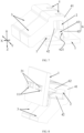
FIG. 1 is a diagram of a stereoscopic structure of an atmosphere lamp according to an embodiment. -
FIG. 2 is a diagram of a stereoscopic structure of an atmosphere lamp from another perspective according to an embodiment. -
FIG. 3 is a schematic diagram of a side-viewing structure of an atmosphere lamp according to an embodiment. -
FIG. 4 is a structurally schematic diagram of a light guide block according to an embodiment. -
FIG. 5 is a schematic diagram of a bottom view of a light guide block according to an embodiment. -
FIG. 6 is a structurally schematic diagram of a main circuit board and an auxiliary circuit board according to an embodiment. -
FIG. 7 is a schematic diagram of a stereoscopic structure of an atmosphere lamp according to another embodiment. -
FIG. 8 is diagram of a stereoscopic structure of an atmosphere lamp from another perspective according to another embodiment. -
FIG. 9 is a structurally schematic diagram of a light guide block according to another embodiment. -
FIG. 10 is a structurally schematic diagram of a main circuit board and an auxiliary circuit board according to another embodiment. - In the drawings,
1: main circuit board; 11: mounting groove; 2: auxiliary circuit board; 21: mounting block; 22: welding pin; 23: light source structure; 24: first groove; 25: second groove; 26: third groove; 27: fourth groove; 3: light guide block; 31: light incident surface; 4: snapping groove; 41: claw; 42: first bump; 5: transverse limiting structure; 51: transverse limiting groove; 52: transverse limiting block; 53: connecting plate; 6: longitudinal limiting structure; 61: longitudinal limiting groove; 62: longitudinal limiting block; 621: guide slope; 622: limiting slope; 7: support structure; 71: second bump; 8: connector. - A clear and complete description of the embodiments of the present disclosure will be set forth with reference to the drawings. The described embodiments are only a part, rather than all, of the embodiments of the present disclosure. All other embodiments derived by persons skilled in the art from the embodiments of the present disclosure without making inventive efforts shall fall within the scope of the present disclosure.
- As illustrated in
FIGS. 1 and7 , the present disclosure provides an atmosphere lamp, which includes at least onemain circuit board 1, at least oneauxiliary circuit board 2 mounted on and electrically connected to themain circuit board 1, and at least onelight guide block 3 provided with at least one snappinggroove 4. Theauxiliary circuit board 2 is provided with at least onelight source structure 23. Thelight guide block 3 is snapped onto theauxiliary circuit board 2 through the snappinggroove 4. Thelight guide block 3 is provided with at least onelight incident surface 31 disposed opposite to thelight source structure 23. For the convenience of describing the positional relationships between various structures, description will be made with reference to directions illustrated inFIGS. 1 and7 , with the height direction being a direction Z, the length direction being a direction Y, and the width direction being a direction X. - In the atmosphere lamp of the present disclosure, the
light guide block 3 is provided with at least one snappinggroove 4 matched with theauxiliary circuit board 2, so that thelight guide block 3 can be directly snapped onto theauxiliary circuit board 2, with thelight incident surface 31 of thelight guide block 3 being corresponding to thelight source structure 23 on theauxiliary circuit board 2, thereby utilizing thelight guide block 3 to guide light rays generated by thelight source structure 23 to be emitted along a specific path. The atmosphere lamp is simple in structure, does not need other tools for snapping and positioning, and also does not need machining a rivet stud on thelight guide block 3 and forming a hole in theauxiliary circuit board 2 for hot riveting, thereby achieving high assembling efficiency and low cost. - Specifically, a width of the snapping
groove 4 is slightly smaller than a thickness of theauxiliary circuit board 2. Thelight source structure 23 includes a plurality of LED particles. Thelight guide block 3 receives, through alight incident surface 31 thereof, light rays generated by the plurality of LED particles, and the light rays are diffusely reflected by thelight guide block 3 and then transferred to the glass of the atmosphere lamp or any other light-transmitting part along a specific path. As illustrated inFIGS. 2 and8 , themain circuit board 1 is provided with a mountinggroove 11, theauxiliary circuit board 2 is provided with a mountingblock 21 inserted into the mountinggroove 11, and theauxiliary circuit board 2 is welded to and fixed on themain circuit board 1 through a plurality of welding pins 22 and is electrically connected to themain circuit board 1. Either of themain circuit board 1 andauxiliary circuit board 2 is a PCBA board. - As illustrated in
FIGS. 4, 5 and9 , in the embodiment of the present disclosure, thelight guide block 3 is provided with at least oneclaw 41 and at least onefirst bump 42, thefirst bump 42 and thelight incident surface 31 are located on the same side of thelight guide block 3, and theclaw 41 and thefirst bump 42 are cooperated to form the snappinggroove 4. By disposing thefirst bump 42, a space for mounting thelight source structure 23 is available between thelight incident surface 31 and theauxiliary circuit board 2. By forming the snappinggroove 4 through the cooperation between thefirst bump 42 and theclaw 41, thelight guide block 3 is ensured to be snapped and fixed on theauxiliary circuit board 2, and thelight guide block 3 and theauxiliary circuit board 2 do not move relative to each other in a width direction of the snappinggroove 4, i.e., a width direction X of theauxiliary circuit board 2 and thelight guide block 3. - Specifically, the
claw 41, thefirst bump 42, and thelight guide block 3 are integrally formed for easy processing. Thelight guide block 3 is provided with a light incident side surface opposite to theauxiliary circuit board 2, and a top surface away from themain circuit board 1 and connected to the side surface. Both thelight incident surface 31 and thefirst bump 42 are located on the light incident side surface of thelight guide block 3. A fixed end of theclaw 41 is connected to the top surface of thelight guide block 3. Theclaw 41 is substantially L-shaped. - As illustrated in
FIGS. 1 and7 , in the embodiments of the present disclosure, a transverse limitingstructure 5 is disposed between thelight guide block 3 and theauxiliary circuit board 2 to limit a relative movement between thelight guide block 3 and theauxiliary circuit board 2 in a length direction of the snappinggroove 4, which is an axial direction of the snappinggroove 4 and is also a length direction Y of theauxiliary circuit board 2 and thelight guide block 3. By disposing the transverse limitingstructure 5, it is ensured that thelight guide block 3 and theauxiliary circuit board 2 do not move relative to each other in the length direction of the snappinggroove 4. - As illustrated in
FIGS. 1 ,5 ,6 ,7 ,9 and 10 , thetransverse limiting structure 5 includes a transverse limitingblock 52 and a transverse limitinggroove 51, and the transverse limitingblock 52 is disposed on theauxiliary circuit board 2 and matched with the transverse limitinggroove 51. Thelight guide block 3 includes a plurality ofclaws 41. The plurality ofclaws 41 and the plurality offirst bumps 42 are cooperated to form a plurality of snappinggrooves 4, and thelight guide block 3 is snapped onto theauxiliary circuit board 2 through the plurality of snappinggrooves 4, so that thelight guide block 3 can be mounted more stably. Specifically, twoclaws 41 are disposed at an interval along the length direction of theauxiliary circuit board 2. - As illustrated in
FIGS. 1 ,5 and6 , in the embodiment, the transverselimiting groove 51 is formed between twoadjacent claws 41, which is simple in structure and easy to process. Specifically, the top surface of theauxiliary circuit board 2 is cut to form afirst groove 24 and asecond groove 25, so that thetransverse stop block 52 is formed between thefirst groove 24 and thesecond groove 25, and the twoclaws 41 are mounted in thefirst groove 24 and thesecond groove 25. - As illustrated in
FIGS. 7 ,9 and 10 , in another embodiment, adjacent two of theclaws 41 are connected through a connectingplate 53 in which the transverse limitinggroove 51 is formed. The connection of the adjacent two of theclaws 41 through the connectingplate 53 can also make the structure of the twoclaws 41 more stable. Specifically, the connectingplate 53 is connected to the top surface of thelight guide block 3. The top surface of theauxiliary circuit board 2 is cut to form athird groove 26 and afourth groove 27, so that the transverse limitingblock 52 is formed between thethird groove 26 and thefourth groove 27, and the twoclaws 41 are mounted in thethird groove 26 and thefourth groove 27. - As illustrated in
FIGS. 1 ,5 ,6 ,7 ,9 and 10 , thelight guide block 3 is an asymmetric structure with respect to a center of the transverse limitinggroove 51. Theauxiliary circuit board 2 is an asymmetric structure with respect to the center of the transverse limitingblock 52. By disposing thelight guide block 3 and theauxiliary circuit board 2 as asymmetric structures, when thelight guide block 3 is mounted from a side of theauxiliary circuit board 2 where thelight source structure 23 is not mounted, thelight guide block 3 cannot be snapped onto theauxiliary circuit board 2 because the transverse limitinggroove 51 on thelight guide block 3 cannot be matched with the transverse limitingblock 52 on theauxiliary circuit board 2, thereby avoiding the mounting error of thelight guide block 3. - As illustrated in
FIGS. 1 ,5 and6 , in the embodiment, thefirst groove 24 is a stepped groove, and thesecond groove 25 is a three-sided open groove, so that theauxiliary circuit board 2 forms an asymmetric structure. The twoclaws 41 are disposed asymmetrically with respect to a center of thelight guide block 3, so that thelight guide block 3 forms an asymmetric structure. - As illustrated in
FIGS. 7 ,9 and 10 , in another embodiment, the transverse limitinggroove 51 is disposed close to one of theclaws 41, so that thelight guide block 3 forms an asymmetric structure. Thethird groove 26 and thefourth groove 27 are both stepped grooves, but an extension dimension of thethird groove 26 in the length direction Y of theauxiliary circuit board 2 is greater than an extension dimension of thefourth groove 27 in the length direction Y of theauxiliary circuit board 2, so that theauxiliary circuit board 2 forms an asymmetric structure. - As illustrated in
FIGS. 1 and7 , in the embodiment of the present disclosure, a longitudinal limiting structure 6 is disposed between thelight guide block 3 and theauxiliary circuit board 2 to limit theauxiliary circuit board 2 from falling out of the snappinggroove 4. By disposing the longitudinal limiting structure 6, thelight guide block 3 and theauxiliary circuit board 2 cannot move relative to each other in the height direction Z after thelight guide block 3 is downwards snapped onto theauxiliary circuit board 2, so that theauxiliary circuit board 2 will not fall out of the snappinggroove 4. - As illustrated in
FIGS. 1 ,5 ,6 ,7 ,9 and 10 , the longitudinal limiting structure 6 includes a longitudinal limitingblock 62 and a longitudinal limitinggroove 61, theclaw 41 has an inner side surface opposite to theauxiliary circuit board 2, the longitudinal limitingblock 62 is disposed on the inner side surface of theclaw 41, and the longitudinal limitinggroove 61 is disposed on theauxiliary circuit board 2 and matched with the longitudinal limitingblock 62. After thelight guide block 3 and theauxiliary circuit board 2 are assembled in place, a downward movement of thelight guide block 3 relative to theauxiliary circuit board 2 is restricted by a bottom surface of the snappinggroove 4, and an upward movement of thelight guide block 3 relative to theauxiliary circuit board 2 is restricted by the longitudinal limitingblock 62. Specifically, the various grooves on theauxiliary circuit board 2 are formed by cutting edge portions of theauxiliary circuit board 2, without needing to form a hole or a groove in a middle portion of theauxiliary circuit board 2, which is easy to process and manufacture. - As illustrated in
FIGS. 3 ,5 ,7 and9 , the longitudinal limitingblock 62 is provided with aguide slope 621 which is inclined towards the outside of the snappinggroove 4 along a mounting direction of the light guide block 3 (i.e., downward along the direction Z). When thelight guide block 3 is downwards snapped onto theauxiliary circuit board 2, theauxiliary circuit board 2 is guided by theguide slope 621 to pass through the longitudinal limitingblock 62 to be snapped into the snappinggroove 4, so that the longitudinal limitingblock 62 is snapped into the longitudinal limitinggroove 61 on theauxiliary circuit board 2. - As illustrated in
FIG. 3 , in this embodiment, the longitudinal limitingblock 62 is further provided with a limitingslope 622, which is inclined towards the inside of the longitudinal limitinggroove 61 along a snapping direction of the longitudinal limitingblock 62. The longitudinal limitingblock 62 is snapped into the longitudinal limitinggroove 61 along the thickness direction of theauxiliary circuit board 2. By disposing the limitingslope 622, an interference fit between the longitudinal limitingblock 62 and the longitudinal limitinggroove 61 can be ensured when there is a height difference between the longitudinal limitingblocks 62 and the longitudinal limitingblocks 62, so as to prevent thelight guide block 3 from moving upwards. - As illustrated in
FIGS. 3 and7 , in the embodiment of the present disclosure, asupport structure 7 is disposed on thelight guide block 3, and abuts against themain circuit board 1 along the mounting direction of thelight guide block 3. Since thelight guide block 3 is supported by themain circuit board 1, the mounting stability of thelight guide block 3 is improved and thelight guide block 3 is prevented from being turned over. - As illustrated in
FIGS. 5 and9 , thesupport structure 7 includes a plurality ofsecond bumps 71 disposed symmetrically with respect to the center of gravity of thelight guide block 3. Specifically, thesupport structure 7 includes twosecond bumps 71 each being a substantially cylindrical structure. The second bumps 71 are integrally formed on a bottom surface of thelight guide block 3 opposite to themain circuit board 1. - A layout angle between the
auxiliary circuit board 2 and themain circuit board 1 is not particularly limited, and as illustrated inFIGS. 1 and7 , in the embodiment of the present disclosure, theauxiliary circuit board 2 has a first end and a second end opposite to each other, the first end of theauxiliary circuit board 2 is connected to themain circuit board 1 and disposed vertically, and thelight guide block 3 is snapped onto theauxiliary circuit board 2 from the second end of theauxiliary circuit board 2 through the snappinggroove 4, so that theauxiliary circuit board 2 can be more stably mounted on themain circuit board 1, and theauxiliary circuit board 2 is less likely to interfere with other electronic components on themain circuit board 1. - As illustrated in
FIG. 1 , in the embodiment, the atmosphere lamp includes a plurality ofmain circuit boards 1, a plurality ofauxiliary circuit boards 2 and a plurality of light guide blocks 3; the plurality ofmain circuit boards 1 are connected and conducted through a connector 8, the plurality ofauxiliary circuit boards 2 are mounted on the plurality ofmain circuit boards 1 in one-to-one correspondence, and the plurality of light guide blocks 3 are mounted on the plurality ofauxiliary circuit boards 2 in one-to-one correspondence. By connecting the plurality ofmain circuit boards 1 through the connector 8 and disposing a plurality of light guide blocks 3, it is convenient to assemble the atmosphere lamp into a desired shape. - As illustrated in
FIGS. 7 and10 , in another embodiment, the plurality ofauxiliary circuit boards 2 are mounted on the samemain circuit board 1. The plurality of light guide blocks 3 are mounted on the plurality ofauxiliary circuit boards 2 in one-to-one correspondence. - Those described above are just several embodiments of the present disclosure, and those skilled in the art can make various modifications or variations to the embodiments of the present disclosure according to the contents disclosed in the application document without departing from the spirit and scope of the present disclosure.
Claims (12)
- An atmosphere lamp, comprising:at least one main circuit board;at least one auxiliary circuit board mounted on and electrically connected to the main circuit board, the auxiliary circuit board being provided with at least one light source structure; andat least one light guide block provided with at least one snapping groove, the light guide block being snapped onto the auxiliary circuit board by the snapping groove, and the light guide block being provided with at least one light incident surface disposed opposite to the light source structure.
- The atmosphere lamp according to claim 1, wherein,
the light guide block is provided with at least one claw and at least one first bump, the first bump and the light incident surface are located on the same side of the light guide block, and the claw and the first bump are cooperated to form the snapping groove. - The atmosphere lamp according to claim 2, wherein,
a transverse limiting structure is disposed between the light guide block and the auxiliary circuit board to limit a relative movement between the light guide block and the auxiliary circuit board in a length direction of the snapping groove. - The atmosphere lamp according to claim 3, wherein,the transverse limiting structure comprises a transverse limiting block and a transverse limiting groove, the transverse limiting block is disposed on the auxiliary circuit board and matched with the transverse limiting groove, and the light guide block comprises a plurality of the claws; andthe transverse limiting groove is formed between adjacent two of the claws; or adjacent two of the claws are connected through a connecting plate and the transverse limiting groove is formed in the connecting plate.
- The atmosphere lamp according to claim 4, wherein,
the light guide block is an asymmetric structure with respect to a center of the transverse limiting groove, and the auxiliary circuit board is an asymmetric structure with respect to the center of the transverse limiting block. - The atmosphere lamp according to claim 2, wherein,
a longitudinal limiting structure is disposed between the light guide block and the auxiliary circuit board to limit the auxiliary circuit board from falling out of the snapping groove. - The atmosphere lamp according to claim 6, wherein,
the longitudinal limiting structure comprises a longitudinal limiting block and a longitudinal limiting groove, the claw has an inner side surface opposite to the auxiliary circuit board, the longitudinal limiting block is disposed on the inner side surface of the claw, and the longitudinal limiting groove is disposed on the auxiliary circuit board and matched with the longitudinal limiting block. - The atmosphere lamp according to claim 7, wherein,
the longitudinal limiting block is provided with a guide slope which is inclined towards the outside of the snapping groove along a mounting direction of the light guide block, and a limiting slope which is inclined towards the inside of the longitudinal limiting groove along a snapping direction of the longitudinal limiting block. - The atmosphere lamp according to claim 1, wherein,
a support structure is disposed on the light guide block, and abuts against the main circuit board along a mounting direction of the light guide block. - The atmosphere lamp according to claim 9, wherein,
the support structure comprises a plurality of second bumps disposed symmetrically with respect to the center of gravity of the light guide block. - The atmosphere lamp according to claim 1, wherein,
the auxiliary circuit board has a first end and a second end opposite to each other, the first end of the auxiliary circuit board is connected to the main circuit board and disposed vertically, and the light guide block is snapped onto the auxiliary circuit board from the second end of the auxiliary circuit board through the snapping groove. - The atmosphere lamp according to claim 1, wherein,
the atmosphere lamp comprises a plurality of main circuit boards, a plurality of auxiliary circuit boards and a plurality of light guide blocks, the plurality of main circuit boards are connected and conducted through a connector, the plurality of auxiliary circuit boards are mounted on the plurality of main circuit boards in one-to-one correspondence, and the plurality of light guide blocks are mounted on the plurality of auxiliary circuit boards in one-to-one correspondence.
Applications Claiming Priority (2)
| Application Number | Priority Date | Filing Date | Title |
|---|---|---|---|
| CN202210777701.0A CN115076660B (en) | 2022-07-04 | 2022-07-04 | Ambient Light |
| PCT/CN2023/104349 WO2024007973A1 (en) | 2022-07-04 | 2023-06-30 | Atmosphere lamp |
Publications (2)
| Publication Number | Publication Date |
|---|---|
| EP4528154A1 true EP4528154A1 (en) | 2025-03-26 |
| EP4528154A4 EP4528154A4 (en) | 2025-09-03 |
Family
ID=83258144
Family Applications (1)
| Application Number | Title | Priority Date | Filing Date |
|---|---|---|---|
| EP23834740.5A Pending EP4528154A4 (en) | 2022-07-04 | 2023-06-30 | ATMOSPHERE LAMP |
Country Status (5)
| Country | Link |
|---|---|
| EP (1) | EP4528154A4 (en) |
| JP (1) | JP7834899B2 (en) |
| KR (1) | KR20250016287A (en) |
| CN (1) | CN115076660B (en) |
| WO (1) | WO2024007973A1 (en) |
Families Citing this family (1)
| Publication number | Priority date | Publication date | Assignee | Title |
|---|---|---|---|---|
| CN115076660B (en) * | 2022-07-04 | 2023-10-20 | 福耀玻璃工业集团股份有限公司 | Ambient Light |
Family Cites Families (22)
| Publication number | Priority date | Publication date | Assignee | Title |
|---|---|---|---|---|
| JP2002040423A (en) * | 2000-07-31 | 2002-02-06 | Optrex Corp | Lighting device for liquid crystal display element |
| JP2004291949A (en) * | 2003-02-14 | 2004-10-21 | Denso Corp | Lighting equipment for vehicle instruments |
| JP2005078832A (en) * | 2003-08-28 | 2005-03-24 | Kawaguchiko Seimitsu Co Ltd | Backlight device |
| JP4062703B2 (en) | 2004-04-28 | 2008-03-19 | スタンレー電気株式会社 | Lighting unit |
| TWI421592B (en) * | 2010-09-24 | 2014-01-01 | Au Optronics Corp | Backlight module |
| KR101358736B1 (en) * | 2012-09-12 | 2014-02-07 | 플러스웰주식회사 | Lighting apparatus using light guide plate |
| JP6063880B2 (en) | 2014-01-31 | 2017-01-18 | 京セラドキュメントソリューションズ株式会社 | Light guide and lighting device |
| TWI541471B (en) * | 2014-11-20 | 2016-07-11 | Lamps and lanterns | |
| KR102339518B1 (en) | 2015-02-25 | 2021-12-16 | 현대모비스 주식회사 | Lamp apparatus for an automobile |
| CN205256156U (en) * | 2015-11-30 | 2016-05-25 | 重庆熠美实业发展有限公司 | LED light source mounting structure |
| US10136020B2 (en) * | 2016-03-18 | 2018-11-20 | Canon Kabushiki Kaisha | Image reading apparatus and image forming apparatus |
| CN107062018A (en) * | 2017-05-27 | 2017-08-18 | 胡挺松 | A kind of new LED light source |
| CN207635030U (en) * | 2017-12-26 | 2018-07-20 | 欧普照明股份有限公司 | Fast-assembling light source module group and lamps and lanterns |
| CN207921774U (en) * | 2018-01-02 | 2018-09-28 | 飞利浦灯具(上海)有限公司 | A kind of rectangle lamps and lanterns |
| CN208397888U (en) * | 2018-07-24 | 2019-01-18 | 安徽泽润光电股份有限公司 | LED flat lamp |
| JP2021034252A (en) | 2019-08-26 | 2021-03-01 | シチズン電子株式会社 | Planar light emitting device |
| CN111559310B (en) * | 2020-05-12 | 2021-08-10 | 福耀玻璃工业集团股份有限公司 | Light source module for skylight atmosphere lamp |
| CN213810202U (en) * | 2020-11-30 | 2021-07-27 | 宁波舜宇精工股份有限公司 | Light guide structure of automobile-used direct light guide formula atmosphere lamp |
| CN216761619U (en) * | 2021-04-30 | 2022-06-17 | 常州九鼎车业股份有限公司 | Blind area auxiliary lamp |
| CN216556762U (en) * | 2022-01-14 | 2022-05-17 | 福耀玻璃工业集团股份有限公司 | Atmosphere lamp and glass assembly |
| CN115076660B (en) * | 2022-07-04 | 2023-10-20 | 福耀玻璃工业集团股份有限公司 | Ambient Light |
| CN218153758U (en) * | 2022-08-30 | 2022-12-27 | 福耀玻璃工业集团股份有限公司 | Novel lamp belt structure |
-
2022
- 2022-07-04 CN CN202210777701.0A patent/CN115076660B/en active Active
-
2023
- 2023-06-30 KR KR1020247042854A patent/KR20250016287A/en active Pending
- 2023-06-30 EP EP23834740.5A patent/EP4528154A4/en active Pending
- 2023-06-30 WO PCT/CN2023/104349 patent/WO2024007973A1/en not_active Ceased
- 2023-06-30 JP JP2024575617A patent/JP7834899B2/en active Active
Also Published As
| Publication number | Publication date |
|---|---|
| CN115076660B (en) | 2023-10-20 |
| JP7834899B2 (en) | 2026-03-24 |
| KR20250016287A (en) | 2025-02-03 |
| JP2025519931A (en) | 2025-06-26 |
| CN115076660A (en) | 2022-09-20 |
| EP4528154A4 (en) | 2025-09-03 |
| WO2024007973A1 (en) | 2024-01-11 |
Similar Documents
| Publication | Publication Date | Title |
|---|---|---|
| CN101662908B (en) | Electrical equipment, a lamp lighting device of a discharging lamp and lighting fixtures | |
| EP4528154A1 (en) | Atmosphere lamp | |
| DE102014101784B4 (en) | Method for building an LED light module | |
| JP2018110101A (en) | Vehicle lamp light assembly | |
| EP2915698A1 (en) | Led light | |
| JP2008034250A (en) | Connector device | |
| EP2597365A2 (en) | Lighting module for a domestic appliance | |
| CN105765644A (en) | Display device | |
| JP2004192976A (en) | Jig for press-fitting terminal and press-fitting device | |
| JP2014179211A (en) | Light source unit and lighting fixture using the same | |
| JP2020064872A (en) | Light emitting device and light emitting system | |
| JP2008292962A (en) | Optical connector fixing structure and optical connector | |
| KR101601390B1 (en) | LED Lamp Of Straight Tube Type | |
| EP4047263B1 (en) | Illumination device | |
| JP2020136140A (en) | Lighting fixture, housing and lighting body | |
| JP2016225250A (en) | Module and module manufacturing method | |
| US11466832B2 (en) | Mounting structure of primary optical element for vehicle headlamp, vehicle lamp and vehicle | |
| JP2016091979A (en) | Module, lighting apparatus, and base member used therein | |
| EP2325046A1 (en) | Method to assembly a turn signal indicator module and turn signal indicator sub-module | |
| US20240097374A1 (en) | Receptacle assembly, cage and mounting method | |
| US20160134033A1 (en) | Connector and illuminating device | |
| US20240413570A1 (en) | Contact-making arrangement, electronics assembly and method for assembling an electronics assembly | |
| EP3258161A1 (en) | Light source module, assembly and lighting and/or signaling apparatus | |
| CN209674090U (en) | It automates reflected light path and adjusts component and regulating device | |
| CN111965782B (en) | Automatic reflection light path adjusting component, adjusting device and using method |
Legal Events
| Date | Code | Title | Description |
|---|---|---|---|
| STAA | Information on the status of an ep patent application or granted ep patent |
Free format text: STATUS: THE INTERNATIONAL PUBLICATION HAS BEEN MADE |
|
| PUAI | Public reference made under article 153(3) epc to a published international application that has entered the european phase |
Free format text: ORIGINAL CODE: 0009012 |
|
| STAA | Information on the status of an ep patent application or granted ep patent |
Free format text: STATUS: REQUEST FOR EXAMINATION WAS MADE |
|
| 17P | Request for examination filed |
Effective date: 20241219 |
|
| AK | Designated contracting states |
Kind code of ref document: A1 Designated state(s): AL AT BE BG CH CY CZ DE DK EE ES FI FR GB GR HR HU IE IS IT LI LT LU LV MC ME MK MT NL NO PL PT RO RS SE SI SK SM TR |
|
| REG | Reference to a national code |
Ref country code: DE Ref legal event code: R079 Free format text: PREVIOUS MAIN CLASS: F21V0017160000 Ipc: B60Q0003640000 |
|
| A4 | Supplementary search report drawn up and despatched |
Effective date: 20250801 |
|
| RIC1 | Information provided on ipc code assigned before grant |
Ipc: B60Q 3/64 20170101AFI20250728BHEP Ipc: F21V 8/00 20060101ALI20250728BHEP Ipc: F21S 8/00 20060101ALI20250728BHEP Ipc: F21V 17/16 20060101ALI20250728BHEP Ipc: F21S 4/28 20160101ALI20250728BHEP Ipc: F21S 4/20 20160101ALI20250728BHEP Ipc: B60Q 3/208 20170101ALI20250728BHEP |
|
| DAV | Request for validation of the european patent (deleted) | ||
| DAX | Request for extension of the european patent (deleted) |