EP4527776A1 - Elevator - Google Patents
Elevator Download PDFInfo
- Publication number
- EP4527776A1 EP4527776A1 EP22942609.3A EP22942609A EP4527776A1 EP 4527776 A1 EP4527776 A1 EP 4527776A1 EP 22942609 A EP22942609 A EP 22942609A EP 4527776 A1 EP4527776 A1 EP 4527776A1
- Authority
- EP
- European Patent Office
- Prior art keywords
- upper frame
- car
- operation mechanism
- drive
- elevator according
- Prior art date
- Legal status (The legal status is an assumption and is not a legal conclusion. Google has not performed a legal analysis and makes no representation as to the accuracy of the status listed.)
- Pending
Links
Images



Classifications
-
- B—PERFORMING OPERATIONS; TRANSPORTING
- B66—HOISTING; LIFTING; HAULING
- B66B—ELEVATORS; ESCALATORS OR MOVING WALKWAYS
- B66B5/00—Applications of checking, fault-correcting, or safety devices in elevators
- B66B5/02—Applications of checking, fault-correcting, or safety devices in elevators responsive to abnormal operating conditions
- B66B5/16—Braking or catch devices operating between cars, cages, or skips and fixed guide elements or surfaces in hoistway or well
- B66B5/18—Braking or catch devices operating between cars, cages, or skips and fixed guide elements or surfaces in hoistway or well and applying frictional retarding forces
-
- B—PERFORMING OPERATIONS; TRANSPORTING
- B66—HOISTING; LIFTING; HAULING
- B66B—ELEVATORS; ESCALATORS OR MOVING WALKWAYS
- B66B11/00—Main component parts of lifts in, or associated with, buildings or other structures
- B66B11/02—Cages, i.e. cars
- B66B11/0206—Car frames
Definitions
- the present invention relates to an elevator including an emergency stop apparatus for stopping a car in an emergency.
- a rope-type elevator includes long objects such as a main rope and a compensation rope that couple a car and a balance weight, and a governor rope used for detecting a speed of the car or the balance weight. Further, it is defined that the elevator is provided with, as a safety apparatus, an emergency stop apparatus that automatically stops an operation of the car when the speed of the car that moves up and down along a guide rail exceeds a defined value.
- PTL 1 discloses the technique in which a brake mechanism that clamps a guide rail and an operation apparatus that operates the brake mechanism of an emergency stop apparatus are accommodated in a vertical frame that constitutes a car.
- the technique disclosed in PTL 1 since the brake mechanism and the operation apparatus of the emergency stop apparatus are provided in the vertical frame of the car, a size of the vertical frame increases. As a result, the technique disclosed in PTL 1 has a problem that a size of a car room of the car is reduced due to the increase in the size of the vertical frame.
- an object of the invention is to provide an elevator capable of preventing an increase in a size of a vertical frame.
- an elevator includes: a car having a car room; a guide rail configured to guide a movement of the car; an upper frame provided on an upper portion of the car room; and an emergency stop apparatus configured to stop the movement of the car.
- the emergency stop apparatus includes a brake mechanism having a braking element configured to clamp the guide rail, a drive mechanism configured to operate the brake mechanism, and an operation mechanism configured to actuate the drive mechanism.
- the drive mechanism and the operation mechanism are accommodated in the upper frame.
- FIGS. 1 to 6 the same members are denoted by the same reference numerals.
- present embodiment a configuration of a car of an elevator according to a first embodiment (hereinafter referred to as "present embodiment") will be described with reference to FIGS. 1 and 2 .
- FIG. 1 is a schematic configuration diagram showing a configuration example of the car according to the present embodiment.
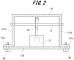
- FIG. 2 is a cross-sectional view taken along a line A-A shown in FIG. 1 .
- a car 1 of the elevator moves up and down in a hoistway formed in a building structure. Further, the car 1 is slidably supported by guide rails 201A and 201B which are provided vertically in the hoistway.
- the car 1 includes a car room 120 in which a person or a baggage is placed, an upper frame (crosshead) 121, a lower frame 130, vertical frames 140, and an emergency stop apparatus.
- the upper frame 121 is provided at an upper portion of the car room 120 in an upper-lower direction
- the lower frame 130 is provided at a lower portion of the car room 120 in the upper-lower direction.
- the vertical frames 140 couple the upper frame 121 and the lower frame 130, and are provided along the upper-lower direction of the car room 120.
- the emergency stop apparatus includes two brake mechanisms 10A and 10B, an operation mechanism 11, a drive mechanism 12, a first lifting member 13A, and a second lifting member 13B. As shown in FIGS. 1 and 2 , the operation mechanism 11 and the drive mechanism 12 are provided in the upper frame 121. A detailed configuration of the upper frame 121 and arrangement states of the operation mechanism 11 and the drive mechanism 12 will be described later.
- the brake mechanisms 10A and 10B are provided at lower end portions of the vertical frames 140 in the upper-lower direction.
- the brake mechanisms 10A and 10B include a pair of braking elements (not shown).
- the pair of braking elements are provided to face each other with the guide rails 201A and 201B interposed therebetween.
- the pair of braking elements are coupled to the lifting members 13A and 13B.
- the pair of braking elements clamp the guide rails 201A and 201B. Accordingly, an upward and downward movement of the car 1 is braked by the brake mechanisms 10A and 10B.
- FIG. 3 is a diagram showing the operation mechanism 11 and the drive mechanism 12.
- the drive mechanism 12 includes a drive shaft 15, a first lifting lever 16A, a second lifting lever 16B, drive shafts 18, 18, and a drive spring 20.
- the drive shafts 18 are provided at both end portions of the upper frame 121 in a width direction orthogonal to the upper-lower direction.
- the lifting levers 16A and 16B are rotatably supported by the drive shafts 18.
- the first lifting lever 16A and the second lifting lever 16B are formed in substantially T-shapes.
- the drive shafts 18 are provided at intersections of the T-shapes of the first lifting lever 16A and the second lifting lever 16B.
- the first lifting member 13A is connected to the first lifting lever 16A via a connection portion 26A
- the second lifting member 13B is connected to the second lifting lever 16B via a connection portion 26B.
- the first lifting lever 16A is connected to the drive shaft 15 via a coupling portion 25
- the second lifting lever 16B is connected to the drive shaft 15 via a coupling portion (not shown).
- an end portion of the first lifting lever 16A on a side opposite from the coupling portion 25 is connected to a connection member 41 of the operation mechanism 11 described later via a lever bracket 37.
- the drive shaft 15 is provided in the upper frame 121 along the width direction of the upper frame 121. One end portion of the drive shaft 15 in an axial direction is connected to the first lifting lever 16A, and the other end portion of the drive shaft 15 in the axial direction is connected to the second lifting lever 16B.
- the drive spring 20 is provided at an intermediate portion of the drive shaft 15 in the axial direction.
- the drive spring 20 is implemented by, for example, a compression coil spring. One end portion of the drive spring 20 is fixed to the upper frame 121 via a fixing portion, and the other end portion of the drive spring 20 is fixed to the drive shaft 15 via a pressing member. The drive spring 20 biases the drive shaft 15 toward the other end portion in the axial direction via the pressing member.
- the drive shaft 15 is biased by the drive spring 20 and moves toward the other end portion in the axial direction. Accordingly, the first lifting lever 16A rotates about the drive shaft 18, so that an end portion to which the first lifting member 13A is connected orients upward in the upper-lower direction.
- the second lifting lever 16B rotates about the drive shaft 18, so that an end portion to which the second lifting member 13B is connected orients upward in the upper-lower direction. As a result, the first lifting member 13A and the second lifting member 13B are lifted upward in the upper-lower direction in conjunction with each other, so that the brake mechanisms 10A and 10B operate.
- the operation mechanism 11 includes the connection member 41, an electromagnetic core 43, a movable iron core 44, a base plate 45, a drive motor 46, a feed screw shaft 47, a feed nut 48, and the drive motor.
- the operation mechanism 11 actuates the drive mechanism 12.
- the base plate 45 is formed of a flat plate-shaped member.
- the base plate 45 is fixed to a placement bracket 123 (see FIGS. 1 and 2 ) of the upper frame 121 to be described later.
- a first shaft support portion 54 and a second shaft support portion 55 are fixed to an upper surface portion of the base plate 45 upward in the upper-lower direction.
- the first shaft support portion 54 is provided at one end portion of the base plate 45, and the second shaft support portion 55 is provided at the other end portion of the base plate 45.
- the first shaft support portion 54 and the second shaft support portion 55 are provided to face each other.
- the feed screw shaft 47 is rotatably supported by the first shaft support portion 54 and the second shaft support portion 55.
- the drive motor 46 is provided in the second shaft support portion 55.
- the drive motor 46 may be provided on a first shaft support portion 54 side.
- a rotary shaft of the drive motor 46 is attached to the feed screw shaft 47 via a coupling.
- a trapezoidal thread is formed on an outer peripheral surface of the feed screw shaft 47.
- the feed nut 48 is screwed to the feed screw shaft 47.
- the electromagnetic core 43 is fixed to the feed nut 48.
- the electromagnetic core 43 is provided with a coil. When power is supplied from a power supply (not shown) to the coil and the coil is energized, an electromagnetic stone is formed by the electromagnetic core 43 and the coil.
- the electromagnetic core 43 faces the movable iron core 44 attached to the connection member 41 to be described later.
- the feed screw shaft 47 rotates.
- the feed screw shaft 47 rotates, so that a rotational force of the feed screw shaft 47 is converted into a force along an axial direction by a screw portion and a screw hole.
- the feed nut 48 moves along the axial direction of the feed screw shaft 47.
- the electromagnetic core 43 to which the feed nut 48 is fixed also moves along the axial direction of the feed screw shaft 47.
- the feed nut 48 moves toward the first shaft support portion 54.
- the drive motor rotates backward (reverse rotation)
- the feed nut 48 moves toward the second shaft support portion 55.
- the second shaft support portion 55 is provided at a standby position for the feed nut 48 and the electromagnetic core 43.
- connection member 41 A coupling hole 41a is formed in the connection member 41.
- a connection pin 36 provided on the lever bracket 37 is inserted into the coupling hole 41a. Therefore, the connection member 41 is rotatably coupled to the first lifting lever 16A via the lever bracket 37.
- the movable iron core 44 is fixed to the connection member 41.
- the movable iron core 44 is supported by the connection member 41 and faces the electromagnetic core 43 fixed to the feed nut 48. In the standby state shown in FIG. 3 , the movable iron core 44 is attracted to the electromagnetic core 43.
- the drive motor 46, the feed screw shaft 47, and the feed nut 48 constitute a moving mechanism that moves the electromagnetic core 43 in directions close to and away from the movable iron core 44.
- the electromagnetic core 43 is provided on the other end portion side of the feed screw shaft 47 in the axial direction.
- the coil of the electromagnetic core 43 is energized to excite the electromagnetic core 43. Accordingly, the electromagnetic core 43 and the coil form the electromagnetic stone.
- the movable iron core 44 is attracted to the electromagnetic core 43. Therefore, one end portion of the first lifting lever 16A is held via the connection member 41 to which the movable iron core 44 is fixed. As a result, the drive shaft 15 connected to the other end portion of the first lifting lever 16A is biased to one end portion in the axial direction against a biasing force of the drive spring 20.
- a control unit determines that a descending speed of the car 1 exceeds a predetermined speed during a descending movement of the car 1, the control unit outputs an operation command signal to the emergency stop apparatus. Accordingly, the energization of the electromagnetic core 43 is cut off. The cutting off of the energization of the electromagnetic core 43 occurs not only when the descending speed of the car 1 exceeds the predetermined speed, but also when the elevator experiences an electricity outage.
- the drive shaft 15 moves toward the other end portion side in the axial direction by the biasing force of the drive spring 20, and the one end portion of the first lifting lever 16A also moves toward the other end portion in the axial direction together with the drive shaft 15.
- the first lifting lever 16A and the second lifting lever 16B rotate about the drive shafts 18.
- the drive mechanism 12 is actuated by the operation mechanism 11.
- the first lifting lever 16A rotates, so that the movable iron core 44 separates from the electromagnetic core 43.
- the connection member 41 can be moved without being affected by a frictional force and a holding force between the feed screw shaft 47 and the feed nut 48 which form the moving mechanism.
- the configurations of the operation mechanism 11 and the drive mechanism 12 are not limited to the above-described examples, and other various configurations can be applied.
- the upper frame 121 indicating the crosshead is a so-called hat-shaped steel material whose upper end portion in the upper-lower direction is closed and whose lower end portion in the upper-lower direction is open.
- the upper frame 121 extend along the width direction above the car room 120 of the car 1 in the upper-lower direction.
- the drive shafts 18 of the drive mechanism 12 are attached to side surface portions 121b of the upper frame 121 in a front-rear direction orthogonal to the upper-lower direction and also orthogonal to the width direction.
- Flange portions 121a are provided at lower end portions of the side surface portions 121b of the upper frame 121 in the upper-lower direction.
- the flange portions 121a are bent outward in the front-rear direction from the lower end portions of the side surface portions 121b.
- the placement bracket 123 is fixed to the flange portions 121a via fixing bolts 90.
- the placement bracket 123 closes a part of an opening of the lower end portion of the upper frame 121 in the upper-lower direction.
- the opening of the lower end portion of the upper frame 121 may be entirely closed by the placement bracket 123.
- the above-described operation mechanism 11 is placed on an upper surface portion of the placement bracket 123 in the upper-lower direction. That is, the operation mechanism 11 and the drive mechanism 12 are accommodated in a space of the upper frame 121. Therefore, the upper frame 121 covers the operation mechanism 11 and the drive mechanism 12 from above in the upper-lower direction. Accordingly, dust and rail oil can be prevented from adhering to the operation mechanism 11 and the drive mechanism 12. As a result, it is possible to prevent the operations of the operation mechanism 11 and the drive mechanism 12 from being hindered by the dust and the rail oil, and to improve reliability of the emergency stop apparatus.
- FIG. 4 is a cross-sectional view showing upper frames and an operation mechanism according to the second embodiment.
- the elevator according to the second embodiment is different from the elevator according to the first embodiment in the configuration of the upper frame. Therefore, only the upper frame will be described here, and portions common to those of the elevator according to the first embodiment will be denoted by the same reference numerals and duplicated description will be omitted.
- two upper frames 126, 126 are provided on an upper portion of the car in the upper-lower direction.
- the upper frame 126 is formed in a substantially U-shape.
- the two upper frames 126, 126 are provided at an interval in the front-rear direction with side surface portions facing each other.
- the drive shafts 18 of the drive mechanism 12 are attached to the side surface portions of the upper frames 126.
- the drive shafts 18 are provided between the two upper frames 126, 126.
- Upper flange portions 126a are formed at upper end portions of the upper frames 126 on the side surface portions in the upper-lower direction
- lower flange portions 126b are formed at lower end portions on the side surface portions in the upper-lower direction.
- the placement bracket 123 is fixed to the lower flange portions 126b via the fixing bolts 90.
- the placement bracket 123 is provided to couple the two upper frames 126, 126.
- the operation mechanism 11 of the emergency stop apparatus is provided on the placement bracket 123. Therefore, the operation mechanism 11 and the drive mechanism 12 are accommodated between the two upper frames 126, 126.
- a cover bracket 221 is fixed to the upper flange portion 126a.
- the cover bracket 221 is provided to couple the two upper frames 126, 126, and covers the operation mechanism 11 and the drive mechanism 12 provided between the two upper frames 126, 126 from above in the upper-lower direction.
- the cover bracket 221 and the upper frames 126 constitute the upper frame indicating the crosshead of the car.
- FIG. 5 is a cross-sectional view showing an upper frame and an operation mechanism according to the third embodiment.
- the elevator according to the third embodiment is different from the elevator according to the first embodiment in the configurations of the upper frame and the placement bracket. Therefore, the upper frame and the placement bracket will be described here, and portions common to those of the elevator according to the first embodiment will be denoted by the same reference numerals and duplicated description will be omitted.
- an upper frame 321 is formed in a hat shape similarly to the upper frame 121 according to the first embodiment.
- Flange portions 321a are provided at lower end portions of side surface portions 321b.
- Holes to which the drive shaft 18 is attached in the side surface portions 321b are long holes extending in the upper-lower direction.
- a placement bracket 323 is fitted between the two side surface portions 321b, 321b of the upper frame 321 to close a part of the opening at a lower end portion of the upper frame 321 in the upper-lower direction.
- Fixing pieces 323a are provided at both end portions of the placement bracket 323 in the front-rear direction.
- the fixing pieces 323a are bent upward in the upper-lower direction from a placement surface on which the operation mechanism 11 is placed.
- the fixing pieces 323a face the side surface portions 321b of the upper frame 321, and are fixed to the side surface portions 321b via the fixing bolts 90.
- a fixing hole through which the fixing bolt 90 is inserted in the fixing piece 323a or the side surface portion 321b is a long hole extending in the upper-lower direction. That is, the placement bracket 323 is provided to be movable in the upper-lower direction with respect to the upper frame 321.
- the elevator according to the fourth embodiment is different from the elevator according to the first embodiment in the configuration of the upper frame. Therefore, only the upper frame will be described here, and portions common to those of the elevator according to the first embodiment will be denoted by the same reference numerals and duplicated description will be omitted.
- both end portions of the upper frame in the width direction are opened, but the invention is not limited thereto, and covers that close both end portions of the upper frame may be provided. Since the dust and the rail oil fall from above in the upper-lower direction, the dust and the rail oil can be prevented from adhering to the operation mechanism 11 and the drive mechanism 12 without providing the covers that close both end portions of the upper frame.
- a housing surrounding the operation mechanism 11 placed on the placement bracket may be provided. Accordingly, it possible to more effectively prevent the dust and the rail oil from adhering to the operation mechanism 11.
- the invention can also be applied to a multi-car elevator in which a plurality of cars move up and down in a single hoistway as the elevator.
Landscapes
- Engineering & Computer Science (AREA)
- Mechanical Engineering (AREA)
- Civil Engineering (AREA)
- Structural Engineering (AREA)
- Cage And Drive Apparatuses For Elevators (AREA)
Abstract
Description
- The present invention relates to an elevator including an emergency stop apparatus for stopping a car in an emergency.
- In general, a rope-type elevator includes long objects such as a main rope and a compensation rope that couple a car and a balance weight, and a governor rope used for detecting a speed of the car or the balance weight. Further, it is defined that the elevator is provided with, as a safety apparatus, an emergency stop apparatus that automatically stops an operation of the car when the speed of the car that moves up and down along a guide rail exceeds a defined value.
- As this type of emergency stop apparatus in the related art, for example, there is a technique disclosed in
PTL 1.PTL 1 discloses the technique in which a brake mechanism that clamps a guide rail and an operation apparatus that operates the brake mechanism of an emergency stop apparatus are accommodated in a vertical frame that constitutes a car. - PTL 1:
US2020/0048040 - However, in the technique disclosed in
PTL 1, since the brake mechanism and the operation apparatus of the emergency stop apparatus are provided in the vertical frame of the car, a size of the vertical frame increases. As a result, the technique disclosed inPTL 1 has a problem that a size of a car room of the car is reduced due to the increase in the size of the vertical frame. - In view of the above problems, an object of the invention is to provide an elevator capable of preventing an increase in a size of a vertical frame.
- In order to solve the above problems and achieve the objective, an elevator includes: a car having a car room; a guide rail configured to guide a movement of the car; an upper frame provided on an upper portion of the car room; and an emergency stop apparatus configured to stop the movement of the car. The emergency stop apparatus includes a brake mechanism having a braking element configured to clamp the guide rail, a drive mechanism configured to operate the brake mechanism, and an operation mechanism configured to actuate the drive mechanism. The drive mechanism and the operation mechanism are accommodated in the upper frame.
- According to the elevator having the above configuration, it is possible to prevent an increase in a size of a vertical frame.
-
- [
FIG. 1] FIG. 1 is a schematic configuration diagram showing a car of an elevator according to a first embodiment. - [
FIG. 2] FIG. 2 is a cross-sectional view taken along a line A-A inFIG. 1 . - [
FIG. 3] FIG. 3 is a diagram showing an operation mechanism and a drive mechanism of an emergency stop apparatus according to the embodiment. - [
FIG. 4] FIG. 4 is a cross-sectional view showing upper frames and an operation mechanism of an elevator according to a second embodiment. - [
FIG. 5] FIG. 5 is a cross-sectional view showing upper frames and an operation mechanism of an elevator according to a third embodiment. - [
FIG. 6] FIG. 6 is a front view showing an upper frame of an elevator according to a fourth embodiment. - Hereinafter, an elevator according to embodiments will be described with reference to
FIGS. 1 to 6 . In the drawings, the same members are denoted by the same reference numerals. - First, a configuration of a car of an elevator according to a first embodiment (hereinafter referred to as "present embodiment") will be described with reference to
FIGS. 1 and2 . -
FIG. 1 is a schematic configuration diagram showing a configuration example of the car according to the present embodiment.FIG. 2 is a cross-sectional view taken along a line A-A shown inFIG. 1 . - As shown in
FIG. 1 , acar 1 of the elevator according to the present embodiment moves up and down in a hoistway formed in a building structure. Further, thecar 1 is slidably supported byguide rails car 1 includes acar room 120 in which a person or a baggage is placed, an upper frame (crosshead) 121, alower frame 130,vertical frames 140, and an emergency stop apparatus. - The
upper frame 121 is provided at an upper portion of thecar room 120 in an upper-lower direction, and thelower frame 130 is provided at a lower portion of thecar room 120 in the upper-lower direction. Thevertical frames 140 couple theupper frame 121 and thelower frame 130, and are provided along the upper-lower direction of thecar room 120. - The emergency stop apparatus includes two
brake mechanisms operation mechanism 11, adrive mechanism 12, afirst lifting member 13A, and asecond lifting member 13B. As shown inFIGS. 1 and2 , theoperation mechanism 11 and thedrive mechanism 12 are provided in theupper frame 121. A detailed configuration of theupper frame 121 and arrangement states of theoperation mechanism 11 and thedrive mechanism 12 will be described later. Thebrake mechanisms vertical frames 140 in the upper-lower direction. - The
brake mechanisms guide rails members lifting members guide rails car 1 is braked by thebrake mechanisms - Next, configurations of the
operation mechanism 11 and thedrive mechanism 12 will be described with reference toFIGS. 1 and3 . -
FIG. 3 is a diagram showing theoperation mechanism 11 and thedrive mechanism 12. - As shown in
FIGS. 1 and3 , thedrive mechanism 12 includes adrive shaft 15, afirst lifting lever 16A, asecond lifting lever 16B,drive shafts drive spring 20. Thedrive shafts 18 are provided at both end portions of theupper frame 121 in a width direction orthogonal to the upper-lower direction. The lifting levers 16A and 16B are rotatably supported by thedrive shafts 18. - The
first lifting lever 16A and thesecond lifting lever 16B are formed in substantially T-shapes. Thedrive shafts 18 are provided at intersections of the T-shapes of thefirst lifting lever 16A and thesecond lifting lever 16B. - The
first lifting member 13A is connected to thefirst lifting lever 16A via aconnection portion 26A, and thesecond lifting member 13B is connected to thesecond lifting lever 16B via aconnection portion 26B. As shown inFIG. 3 , thefirst lifting lever 16A is connected to thedrive shaft 15 via acoupling portion 25. Similarly, thesecond lifting lever 16B is connected to thedrive shaft 15 via a coupling portion (not shown). Further, an end portion of thefirst lifting lever 16A on a side opposite from thecoupling portion 25 is connected to aconnection member 41 of theoperation mechanism 11 described later via alever bracket 37. - The
drive shaft 15 is provided in theupper frame 121 along the width direction of theupper frame 121. One end portion of thedrive shaft 15 in an axial direction is connected to thefirst lifting lever 16A, and the other end portion of thedrive shaft 15 in the axial direction is connected to thesecond lifting lever 16B. Thedrive spring 20 is provided at an intermediate portion of thedrive shaft 15 in the axial direction. - The
drive spring 20 is implemented by, for example, a compression coil spring. One end portion of thedrive spring 20 is fixed to theupper frame 121 via a fixing portion, and the other end portion of thedrive spring 20 is fixed to thedrive shaft 15 via a pressing member. Thedrive spring 20 biases thedrive shaft 15 toward the other end portion in the axial direction via the pressing member. - When the
operation mechanism 11 is actuated, thedrive shaft 15 is biased by thedrive spring 20 and moves toward the other end portion in the axial direction. Accordingly, thefirst lifting lever 16A rotates about thedrive shaft 18, so that an end portion to which thefirst lifting member 13A is connected orients upward in the upper-lower direction. In addition, thesecond lifting lever 16B rotates about thedrive shaft 18, so that an end portion to which thesecond lifting member 13B is connected orients upward in the upper-lower direction. As a result, thefirst lifting member 13A and thesecond lifting member 13B are lifted upward in the upper-lower direction in conjunction with each other, so that thebrake mechanisms - As shown in
FIG. 3 , theoperation mechanism 11 includes theconnection member 41, anelectromagnetic core 43, amovable iron core 44, abase plate 45, adrive motor 46, afeed screw shaft 47, afeed nut 48, and the drive motor. Theoperation mechanism 11 actuates thedrive mechanism 12. - The
base plate 45 is formed of a flat plate-shaped member. Thebase plate 45 is fixed to a placement bracket 123 (seeFIGS. 1 and2 ) of theupper frame 121 to be described later. A firstshaft support portion 54 and a secondshaft support portion 55 are fixed to an upper surface portion of thebase plate 45 upward in the upper-lower direction. - The first
shaft support portion 54 is provided at one end portion of thebase plate 45, and the secondshaft support portion 55 is provided at the other end portion of thebase plate 45. The firstshaft support portion 54 and the secondshaft support portion 55 are provided to face each other. Thefeed screw shaft 47 is rotatably supported by the firstshaft support portion 54 and the secondshaft support portion 55. Thedrive motor 46 is provided in the secondshaft support portion 55. Thedrive motor 46 may be provided on a firstshaft support portion 54 side. A rotary shaft of thedrive motor 46 is attached to thefeed screw shaft 47 via a coupling. - A trapezoidal thread is formed on an outer peripheral surface of the
feed screw shaft 47. Thefeed nut 48 is screwed to thefeed screw shaft 47. Theelectromagnetic core 43 is fixed to thefeed nut 48. Theelectromagnetic core 43 is provided with a coil. When power is supplied from a power supply (not shown) to the coil and the coil is energized, an electromagnetic stone is formed by theelectromagnetic core 43 and the coil. Theelectromagnetic core 43 faces themovable iron core 44 attached to theconnection member 41 to be described later. - When the drive motor rotates, the feed screw shaft rotates. The
feed screw shaft 47 rotates, so that a rotational force of thefeed screw shaft 47 is converted into a force along an axial direction by a screw portion and a screw hole. Thefeed nut 48 moves along the axial direction of thefeed screw shaft 47. Theelectromagnetic core 43 to which thefeed nut 48 is fixed also moves along the axial direction of thefeed screw shaft 47. - When the drive motor rotates forward (regular rotation), the
feed nut 48 moves toward the firstshaft support portion 54. When the drive motor rotates backward (reverse rotation), thefeed nut 48 moves toward the secondshaft support portion 55. Here, the secondshaft support portion 55 is provided at a standby position for thefeed nut 48 and theelectromagnetic core 43. When theoperation mechanism 11 returns to a standby state and a return state from a braking state, theelectromagnetic core 43 abuts on the secondshaft support portion 55 via thefeed nut 48. - A
coupling hole 41a is formed in theconnection member 41. Aconnection pin 36 provided on thelever bracket 37 is inserted into thecoupling hole 41a. Therefore, theconnection member 41 is rotatably coupled to thefirst lifting lever 16A via thelever bracket 37. - The
movable iron core 44 is fixed to theconnection member 41. Themovable iron core 44 is supported by theconnection member 41 and faces theelectromagnetic core 43 fixed to thefeed nut 48. In the standby state shown inFIG. 3 , themovable iron core 44 is attracted to theelectromagnetic core 43. - The
drive motor 46, thefeed screw shaft 47, and thefeed nut 48 constitute a moving mechanism that moves theelectromagnetic core 43 in directions close to and away from themovable iron core 44. - In the standby state, the
electromagnetic core 43 is provided on the other end portion side of thefeed screw shaft 47 in the axial direction. The coil of theelectromagnetic core 43 is energized to excite theelectromagnetic core 43. Accordingly, theelectromagnetic core 43 and the coil form the electromagnetic stone. - The
movable iron core 44 is attracted to theelectromagnetic core 43. Therefore, one end portion of thefirst lifting lever 16A is held via theconnection member 41 to which themovable iron core 44 is fixed. As a result, thedrive shaft 15 connected to the other end portion of thefirst lifting lever 16A is biased to one end portion in the axial direction against a biasing force of thedrive spring 20. - When a control unit determines that a descending speed of the
car 1 exceeds a predetermined speed during a descending movement of thecar 1, the control unit outputs an operation command signal to the emergency stop apparatus. Accordingly, the energization of theelectromagnetic core 43 is cut off. The cutting off of the energization of theelectromagnetic core 43 occurs not only when the descending speed of thecar 1 exceeds the predetermined speed, but also when the elevator experiences an electricity outage. - When the energization of the
electromagnetic core 43 is cut off, magnetism of theelectromagnetic core 43 is eliminated. Accordingly, thedrive shaft 15 moves toward the other end portion side in the axial direction by the biasing force of thedrive spring 20, and the one end portion of thefirst lifting lever 16A also moves toward the other end portion in the axial direction together with thedrive shaft 15. As a result, thefirst lifting lever 16A and thesecond lifting lever 16B rotate about thedrive shafts 18. As described above, thedrive mechanism 12 is actuated by theoperation mechanism 11. - The
first lifting lever 16A rotates, so that themovable iron core 44 separates from theelectromagnetic core 43. In this manner, by separating themovable iron core 44 from theelectromagnetic core 43, theconnection member 41 can be moved without being affected by a frictional force and a holding force between thefeed screw shaft 47 and thefeed nut 48 which form the moving mechanism. - The configurations of the
operation mechanism 11 and thedrive mechanism 12 are not limited to the above-described examples, and other various configurations can be applied. - Next, a configuration of the
upper frame 121 and an arrangement state of theoperation mechanism 11 will be described with reference toFIGS. 1 and2 . - As shown in
FIGS. 1 and2 , theupper frame 121 indicating the crosshead is a so-called hat-shaped steel material whose upper end portion in the upper-lower direction is closed and whose lower end portion in the upper-lower direction is open. Theupper frame 121 extend along the width direction above thecar room 120 of thecar 1 in the upper-lower direction. Thedrive shafts 18 of thedrive mechanism 12 are attached toside surface portions 121b of theupper frame 121 in a front-rear direction orthogonal to the upper-lower direction and also orthogonal to the width direction. -
Flange portions 121a are provided at lower end portions of theside surface portions 121b of theupper frame 121 in the upper-lower direction. Theflange portions 121a are bent outward in the front-rear direction from the lower end portions of theside surface portions 121b. Theplacement bracket 123 is fixed to theflange portions 121a via fixingbolts 90. Theplacement bracket 123 closes a part of an opening of the lower end portion of theupper frame 121 in the upper-lower direction. The opening of the lower end portion of theupper frame 121 may be entirely closed by theplacement bracket 123. - The above-described
operation mechanism 11 is placed on an upper surface portion of theplacement bracket 123 in the upper-lower direction. That is, theoperation mechanism 11 and thedrive mechanism 12 are accommodated in a space of theupper frame 121. Therefore, theupper frame 121 covers theoperation mechanism 11 and thedrive mechanism 12 from above in the upper-lower direction. Accordingly, dust and rail oil can be prevented from adhering to theoperation mechanism 11 and thedrive mechanism 12. As a result, it is possible to prevent the operations of theoperation mechanism 11 and thedrive mechanism 12 from being hindered by the dust and the rail oil, and to improve reliability of the emergency stop apparatus. - In addition, by accommodating the
operation mechanism 11 and thedrive mechanism 12 of the emergency stop apparatus in theupper frame 121, it is possible to prevent an increase in a size of thevertical frame 140 of thecar 1. As a result, it is possible to prevent the increase in the size of thevertical frame 140, and thus it is possible to prevent a horizontal dimension of thecar room 120 from being reduced by thevertical frame 140. - Next, an elevator according to a second embodiment will be described with reference to
FIG. 4 . -
FIG. 4 is a cross-sectional view showing upper frames and an operation mechanism according to the second embodiment. - The elevator according to the second embodiment is different from the elevator according to the first embodiment in the configuration of the upper frame. Therefore, only the upper frame will be described here, and portions common to those of the elevator according to the first embodiment will be denoted by the same reference numerals and duplicated description will be omitted.
- As shown in
FIG. 4 , twoupper frames upper frame 126 is formed in a substantially U-shape. The twoupper frames drive shafts 18 of thedrive mechanism 12 are attached to the side surface portions of theupper frames 126. Thedrive shafts 18 are provided between the twoupper frames Upper flange portions 126a are formed at upper end portions of theupper frames 126 on the side surface portions in the upper-lower direction, andlower flange portions 126b are formed at lower end portions on the side surface portions in the upper-lower direction. - The
placement bracket 123 is fixed to thelower flange portions 126b via the fixingbolts 90. Theplacement bracket 123 is provided to couple the twoupper frames operation mechanism 11 of the emergency stop apparatus is provided on theplacement bracket 123. Therefore, theoperation mechanism 11 and thedrive mechanism 12 are accommodated between the twoupper frames - A
cover bracket 221 is fixed to theupper flange portion 126a. Thecover bracket 221 is provided to couple the twoupper frames operation mechanism 11 and thedrive mechanism 12 provided between the twoupper frames cover bracket 221 and theupper frames 126 constitute the upper frame indicating the crosshead of the car. - Since the other configuration is the same as that of the elevator according to the first embodiment, the description thereof will be omitted, but in the elevator according to the second embodiment including such an
upper frame 126, the same action and effect can be obtained as in the elevator according to the first embodiment described above. - Next, an elevator according to a third embodiment will be described with reference to
FIG. 5 . -
FIG. 5 is a cross-sectional view showing an upper frame and an operation mechanism according to the third embodiment. - The elevator according to the third embodiment is different from the elevator according to the first embodiment in the configurations of the upper frame and the placement bracket. Therefore, the upper frame and the placement bracket will be described here, and portions common to those of the elevator according to the first embodiment will be denoted by the same reference numerals and duplicated description will be omitted.
- As shown in
FIG. 5 , anupper frame 321 is formed in a hat shape similarly to theupper frame 121 according to the first embodiment.Flange portions 321a are provided at lower end portions ofside surface portions 321b. Holes to which thedrive shaft 18 is attached in theside surface portions 321b are long holes extending in the upper-lower direction. - A
placement bracket 323 is fitted between the twoside surface portions upper frame 321 to close a part of the opening at a lower end portion of theupper frame 321 in the upper-lower direction. Fixingpieces 323a are provided at both end portions of theplacement bracket 323 in the front-rear direction. The fixingpieces 323a are bent upward in the upper-lower direction from a placement surface on which theoperation mechanism 11 is placed. The fixingpieces 323a face theside surface portions 321b of theupper frame 321, and are fixed to theside surface portions 321b via the fixingbolts 90. A fixing hole through which the fixingbolt 90 is inserted in thefixing piece 323a or theside surface portion 321b is a long hole extending in the upper-lower direction. That is, theplacement bracket 323 is provided to be movable in the upper-lower direction with respect to theupper frame 321. - By using the above-described fixing method for the
placement bracket 323, a height of an attachment position of theplacement bracket 323 can be adjusted. As a result, it is possible to adjust provision positions of theoperation mechanism 11 and thedrive shaft 18 of thedrive mechanism 12 placed on theplacement bracket 323 in the upper-lower direction. - Since the other configuration is the same as that of the elevator according to the first embodiment, the description thereof will be omitted, but in the elevator according to the third embodiment including such a configuration, the same action and effect can be obtained as in the elevator according to the first embodiment described above.
- Next, an elevator according to a fourth embodiment will be described with reference to
FIG. 6 . -
FIG. 6 is a front view showing an upper frame according to the fourth embodiment. - The elevator according to the fourth embodiment is different from the elevator according to the first embodiment in the configuration of the upper frame. Therefore, only the upper frame will be described here, and portions common to those of the elevator according to the first embodiment will be denoted by the same reference numerals and duplicated description will be omitted.
- As shown in
FIG. 6 , anopening window 128 is formed in a side surface portion of anupper frame 121B. Theopening window 128 is formed at a position facing theoperation mechanism 11 accommodated in theupper frame 121B. Theopening window 128 is covered by a cover member (not shown) in an openable and closable manner. By providing theopening window 128 in theupper frame 121B, it is possible to check a state of theoperation mechanism 11 during assembly, and to easily and visually perform check and inspect work. - Since the other configuration is the same as that of the elevator according to the first embodiment, the description thereof will be omitted, but in the elevator according to the fourth embodiment including such an
upper frame 121B, the same action and effect can be obtained as in the elevator according to the first embodiment described above. - The invention is not limited to the embodiments described above and shown in the drawings, and various modifications can be made without departing from the scope of the invention described in the claims.
- In the above-described embodiment, both end portions of the upper frame in the width direction are opened, but the invention is not limited thereto, and covers that close both end portions of the upper frame may be provided. Since the dust and the rail oil fall from above in the upper-lower direction, the dust and the rail oil can be prevented from adhering to the
operation mechanism 11 and thedrive mechanism 12 without providing the covers that close both end portions of the upper frame. - In addition, a housing surrounding the
operation mechanism 11 placed on the placement bracket may be provided. Accordingly, it possible to more effectively prevent the dust and the rail oil from adhering to theoperation mechanism 11. - Further, the invention can also be applied to a multi-car elevator in which a plurality of cars move up and down in a single hoistway as the elevator.
- In the present specification, terms such as "parallel" and "orthogonal" are used, but these terms do not mean only strict "parallel" and "orthogonal", and may be in a state of "substantially parallel" or "substantially orthogonal" including "parallel" and "orthogonal" and within a range in which functions thereof can be exhibited.
-
- 1: car
- 10A, 10B: brake mechanism
- 11: operation mechanism
- 12: drive mechanism
- 13A, 13B: lifting member
- 16A, 16B: lifting lever
- 18: drive shaft
- 41: connection member
- 43: electromagnetic core
- 44: movable iron core
- 46: drive motor
- 90: fixing bolt
- 120: car room
- 121, 121B, 126, 321: upper frame
- 121b: side surface portion
- 123, 323: placement bracket
- 128: opening window
- 130: lower frame
- 140: vertical frame
- 201A, 201B: guide rail
- 221: cover bracket
Claims (6)
- An elevator comprising:a car having a car room;a guide rail configured to guide a movement of the car;an upper frame provided on an upper portion of the car room; andan emergency stop apparatus configured to stop the movement of the car, whereinthe emergency stop apparatus includesa brake mechanism having a braking element configured to clamp the guide rail,a drive mechanism configured to operate the brake mechanism, andan operation mechanism configured to actuate the drive mechanism, andthe drive mechanism and the operation mechanism are accommodated in the upper frame.
- The elevator according to claim 1, whereinthe upper frame is formed in a hat shape in which an upper portion in an upper-lower direction is closed, andthe drive mechanism and the operation mechanism are accommodated in the upper frame.
- The elevator according to claim 1, whereintwo of the upper frames are provided at an interval in a front-rear direction orthogonal to an upper-lower direction and orthogonal to a width direction in which the upper frame extends,the drive mechanism and the operation mechanism are accommodated between the two upper frames, anda cover bracket is fixed to the two upper frames to cover the drive mechanism and the operation mechanism from above in the upper-lower direction.
- The elevator according to claim 1, wherein
a placement bracket on which the operation mechanism is placed is fixed to the upper frame. - The elevator according to claim 4, wherein
the placement bracket is provided to be movable in an upper-lower direction with respect to the upper frame. - The elevator according to claim 1, wherein
an opening window facing the operation mechanism is formed in the upper frame.
Applications Claiming Priority (1)
| Application Number | Priority Date | Filing Date | Title |
|---|---|---|---|
| PCT/JP2022/020459 WO2023223404A1 (en) | 2022-05-17 | 2022-05-17 | Elevator |
Publications (2)
| Publication Number | Publication Date |
|---|---|
| EP4527776A1 true EP4527776A1 (en) | 2025-03-26 |
| EP4527776A4 EP4527776A4 (en) | 2026-04-01 |
Family
ID=88834815
Family Applications (1)
| Application Number | Title | Priority Date | Filing Date |
|---|---|---|---|
| EP22942609.3A Pending EP4527776A4 (en) | 2022-05-17 | 2022-05-17 | ELEVATOR |
Country Status (4)
| Country | Link |
|---|---|
| EP (1) | EP4527776A4 (en) |
| JP (1) | JP7765623B2 (en) |
| CN (1) | CN119032059A (en) |
| WO (1) | WO2023223404A1 (en) |
Family Cites Families (4)
| Publication number | Priority date | Publication date | Assignee | Title |
|---|---|---|---|---|
| JPS61157578U (en) * | 1985-03-20 | 1986-09-30 | ||
| JP2009046274A (en) * | 2007-08-22 | 2009-03-05 | Mitsubishi Electric Building Techno Service Co Ltd | Hoisting/lowering preventive device and elevator device |
| EP3670414B1 (en) * | 2018-12-20 | 2023-06-14 | KONE Corporation | An elevator safety gear trigger and reset system |
| JP7157718B2 (en) * | 2019-09-06 | 2022-10-20 | 株式会社日立製作所 | Emergency stop device and elevator |
-
2022
- 2022-05-17 CN CN202280095572.5A patent/CN119032059A/en active Pending
- 2022-05-17 EP EP22942609.3A patent/EP4527776A4/en active Pending
- 2022-05-17 JP JP2024521411A patent/JP7765623B2/en active Active
- 2022-05-17 WO PCT/JP2022/020459 patent/WO2023223404A1/en not_active Ceased
Also Published As
| Publication number | Publication date |
|---|---|
| JP7765623B2 (en) | 2025-11-06 |
| CN119032059A (en) | 2024-11-26 |
| WO2023223404A1 (en) | 2023-11-23 |
| EP4527776A4 (en) | 2026-04-01 |
| JPWO2023223404A1 (en) | 2023-11-23 |
Similar Documents
| Publication | Publication Date | Title |
|---|---|---|
| EP1067084B1 (en) | Device and method for avoiding vertical slippage and oscillations in load pick up means of conveyor facilities | |
| EP0985623B1 (en) | Emergency stop device for elevator | |
| US9309091B2 (en) | Elevator installation with car and counterweight | |
| KR101033343B1 (en) | Elevator safety device | |
| CN102196985B (en) | Elevator | |
| US6021872A (en) | Remote brake release mechanism for an elevator machine | |
| US9809420B2 (en) | Compensatory measure for low overhead or low pit elevator | |
| EP2107029A1 (en) | Elevator apparatus | |
| KR101124931B1 (en) | Safety device for elevator | |
| US20100089705A1 (en) | Apparatus and method for holding and braking an elevator car | |
| AU2005244549A1 (en) | Lift installation with a breaking device, and method for braking and stopping a lift installation | |
| JP2010514645A (en) | Elevating system having an elevator box with a brake device for holding and braking the elevator box in the area of the elevator box and a method for holding and braking an elevator box of this type | |
| JP7558754B2 (en) | Emergency stop devices and elevators | |
| EP1454867A1 (en) | Elevator | |
| JP2005239329A (en) | Control device for maintaining elevator | |
| EP4527777A1 (en) | Elevator | |
| JP6751373B2 (en) | Emergency stop device and elevator | |
| JP7216839B2 (en) | elevator equipment | |
| JP7765623B2 (en) | elevator | |
| KR200361132Y1 (en) | The rope brake for elevator | |
| WO2024111042A1 (en) | Elevator, and method for restoring emergency stop device | |
| WO2005121006A1 (en) | Emergency brake device for elevator | |
| JP7569268B2 (en) | Emergency stop device, elevator, and method for resetting the emergency stop device | |
| JPH0829903B2 (en) | Elevator emergency stop device | |
| JP7858840B2 (en) | Elevator equipment |
Legal Events
| Date | Code | Title | Description |
|---|---|---|---|
| STAA | Information on the status of an ep patent application or granted ep patent |
Free format text: STATUS: THE INTERNATIONAL PUBLICATION HAS BEEN MADE |
|
| PUAI | Public reference made under article 153(3) epc to a published international application that has entered the european phase |
Free format text: ORIGINAL CODE: 0009012 |
|
| STAA | Information on the status of an ep patent application or granted ep patent |
Free format text: STATUS: REQUEST FOR EXAMINATION WAS MADE |
|
| 17P | Request for examination filed |
Effective date: 20241017 |
|
| AK | Designated contracting states |
Kind code of ref document: A1 Designated state(s): AL AT BE BG CH CY CZ DE DK EE ES FI FR GB GR HR HU IE IS IT LI LT LU LV MC MK MT NL NO PL PT RO RS SE SI SK SM TR |
|
| DAV | Request for validation of the european patent (deleted) | ||
| DAX | Request for extension of the european patent (deleted) | ||
| A4 | Supplementary search report drawn up and despatched |
Effective date: 20260227 |
|
| RIC1 | Information provided on ipc code assigned before grant |
Ipc: B66B 5/22 20060101AFI20260223BHEP Ipc: B66B 5/18 20060101ALI20260223BHEP Ipc: B66B 11/02 20060101ALI20260223BHEP |