EP4527433A1 - Ensemble piston de seringue avec tête de tige de piston de diamètre réduit - Google Patents
Ensemble piston de seringue avec tête de tige de piston de diamètre réduit Download PDFInfo
- Publication number
- EP4527433A1 EP4527433A1 EP23306569.7A EP23306569A EP4527433A1 EP 4527433 A1 EP4527433 A1 EP 4527433A1 EP 23306569 A EP23306569 A EP 23306569A EP 4527433 A1 EP4527433 A1 EP 4527433A1
- Authority
- EP
- European Patent Office
- Prior art keywords
- syringe
- stopper
- head
- rib
- plunger rod
- Prior art date
- Legal status (The legal status is an assumption and is not a legal conclusion. Google has not performed a legal analysis and makes no representation as to the accuracy of the status listed.)
- Pending
Links
Images



Classifications
-
- A—HUMAN NECESSITIES
- A61—MEDICAL OR VETERINARY SCIENCE; HYGIENE
- A61M—DEVICES FOR INTRODUCING MEDIA INTO, OR ONTO, THE BODY; DEVICES FOR TRANSDUCING BODY MEDIA OR FOR TAKING MEDIA FROM THE BODY; DEVICES FOR PRODUCING OR ENDING SLEEP OR STUPOR
- A61M5/00—Devices for bringing media into the body in a subcutaneous, intra-vascular or intramuscular way; Accessories therefor, e.g. filling or cleaning devices, arm-rests
- A61M5/178—Syringes
- A61M5/31—Details
- A61M5/315—Pistons; Piston-rods; Guiding, blocking or restricting the movement of the rod or piston; Appliances on the rod for facilitating dosing ; Dosing mechanisms
- A61M5/31511—Piston or piston-rod constructions, e.g. connection of piston with piston-rod
- A61M5/31513—Piston constructions to improve sealing or sliding
-
- A—HUMAN NECESSITIES
- A61—MEDICAL OR VETERINARY SCIENCE; HYGIENE
- A61M—DEVICES FOR INTRODUCING MEDIA INTO, OR ONTO, THE BODY; DEVICES FOR TRANSDUCING BODY MEDIA OR FOR TAKING MEDIA FROM THE BODY; DEVICES FOR PRODUCING OR ENDING SLEEP OR STUPOR
- A61M5/00—Devices for bringing media into the body in a subcutaneous, intra-vascular or intramuscular way; Accessories therefor, e.g. filling or cleaning devices, arm-rests
- A61M5/178—Syringes
- A61M5/31—Details
- A61M5/315—Pistons; Piston-rods; Guiding, blocking or restricting the movement of the rod or piston; Appliances on the rod for facilitating dosing ; Dosing mechanisms
- A61M5/31511—Piston or piston-rod constructions, e.g. connection of piston with piston-rod
- A61M5/31515—Connection of piston with piston rod
Definitions
- the present disclosure relates generally to syringes and, more particularly, to a plunger assembly of a syringe that includes a thin head plunger rod that mates with a stopper.
- Medical injection devices such as syringes, are used in a variety of environments for administering liquids (e.g., medications or drugs) to a patient.
- liquids e.g., medications or drugs
- Many syringes are provided as prefilled syringes, which provide the convenience of rapidly delivering the liquid therein to a patient without the need to first aspirate the medication from another container and meter its volume.
- the prefilled syringe will typically include a syringe barrel with a plunger assembly inserted through an open proximal end of the barrel and an opening at the opposite distal end adapted to receive a needle therein by which a fluid is injected into the patient.
- the plunger assembly typically includes an elongated plunger rod extending out of the barrel, and a plunger head or stopper disposed at the distal end of the plunger rod.
- the stopper is typically made of elastomeric material and is adapted to ensure the container closure integrity of a syringe when the stopper is inserted into the syringe.
- Existing stopper designs include a stopper body having a tail portion disposed at its proximal end adapted for attachment to the distal end of the plunger rod, and a head portion disposed at its distal end adapted to interfit with the barrel of the syringe.
- the head portion of the stopper may include a plurality of annular, outwardly protruding ribs formed on an external cylindrical wall thereof, with the ribs forming a seal with the syringe barrel to ensure the container closure integrity of the syringe.
- a series of two or three ribs, for example, may be spaced apart longitudinally along the stopper main body.
- a stopper having an outer diameter of around 9.0 mm may include a cavity formed in the tail portion thereof having an inner diameter of 6.0 mm, with the plunger head having an outer diameter just slightly smaller than the inner diameter of the cavity, so as to fill a majority of the cavity when mated therewith.
- a stopper having an outer diameter of around 6.6 mm may include a cavity formed in the tail portion thereof having an inner diameter of 4.0 mm, with the plunger head again having an outer diameter just slightly smaller than the inner diameter of the cavity, so as to fill a majority of the cavity when mated therewith.
- the design may negatively affect the syringe design and use thereof. That is, the wide design of the stopper plunger head may result in an increase in the radially outward force applied by the back stopper rib against the syringe barrel, due to the plunger head increasing the stiffness of this area of the stopper.
- the increased contact pressure applied by the back stopper rib thereby increases a gliding force of the stopper when the plunger assembly is pushed/advanced distally into/through the syringe barrel. This increase in the gliding force may make it more difficult for an operator to advance the plunger assembly in a smooth and effortless manner, and may also negatively affect the seal quality between the stopper and the syringe barrel.
- the plunger rod assembly design would allow for a consistent and desirable gliding force to be maintained between the stopper and the syringe barrel, so as to enable a user-friendly operation of the syringe.
- a syringe including a syringe barrel having a barrel proximal end and a barrel distal end and defining a chamber configured for containing a fluid therein, and a plunger assembly axially movable within the chamber of the syringe barrel between a retracted position and an advanced position.
- the plunger assembly includes a plunger rod having a plunger rod proximal end and a plunger rod distal end, with the plunger rod distal end comprising a plunger rod head including a head shaft and a head tip.
- the plunger assembly also includes a stopper secured to the plunger rod distal end.
- the stopper includes a main body portion defining a proximal end and a distal end, with the main body defining an opening at the proximal end providing access to an inner cavity of the main body portion that is configured to mate with the plunger rod head to secure the stopper to the plunger rod.
- the stopper also includes a plurality of ribs extending from an outer surface of the main body portion and around an outer circumference of the main body portion, with the plurality of ribs including at least a distal rib and a proximal rib.
- a ratio, R, of an outer diameter of the head shaft, OD head_shaft , to an outer diameter of the stopper at the proximal rib, OD rib_prox , defined as R OD head_shaft /OD rib_prox , is 0.4 or less.
- the stopper comprises a threaded inner surface defining the cavity
- the head tip comprises a flat head with two radially opposed wings configured to engage the threaded inner surface via a threading engagement
- the stopper comprises a threaded inner surface defining the cavity
- the head tip comprises a flat head with two radially opposed wings configured to engage the threaded inner surface via a threading engagement
- the cavity comprises a main cylindrical cavity and a distal chamber separated by a bump
- the head tip comprises a flat tip configured to engage the distal chamber and be retained therein by the bump
- a contact pressure applied by the first rib against the syringe barrel and a contact pressure applied by the second rib against the syringe barrel are equal.
- the proximal rib is positioned on the main body portion so as to be axially aligned with a portion of the threaded inner cavity.
- the cavity is sized to receive a vent tube pushing rod therein, to enable placement of the stopper into the syringe barrel via a vent tube stoppering process.
- the stopper is formed of a first material and the plunger rod is formed of a second material, the second material having a greater stiffness than the first material.
- the stopper comprises a coating applied thereto, the coating comprising an inert material and/or a lubricant.
- the distal end of a component or of a device means the end furthest away from the hand of the user and the proximal end means the end closest to the hand of the user, when the component or device is in the use position.
- the distal end is the end thereof that includes a needle (or luer connection), while the proximal end is where the user engages the plunger (i.e., the plunger thumb press).
- the terms “in the distal direction” and “distally” mean in the direction toward the distal tip of the syringe, and the terms “in the proximal direction” and “proximally” mean in the direction opposite the direction of the distal tip of the syringe (i.e., in the direction of the plunger thumb press).
- the syringe 10 may be provided as a prefilled syringe, which provides the convenience of rapidly delivering the liquid therein to a patient without the need to first aspirate the medication from another container and meter its volume.
- the syringe 10 generally includes a syringe barrel 12 and a plunger assembly 14.
- the plunger assembly 14 is movable within the syringe barrel 12 along a longitudinal axis to an advanced position to facilitate administering of an injectable fluid (e.g., medication) to a patient, for example.
- the syringe barrel 12 is formed of a generally cylindrical wall 16 and an end member 18 that collectively define a chamber 20 for retaining fluid therein.
- the syringe barrel 12 includes an open proximal end 22 configured to receive the plunger assembly 14 therein and a distal end 24 at which end member 18 is positioned.
- the proximal end 22 of the syringe barrel 12 may include a flange 26 to facilitate handling and positioning of the syringe 10 and to maintain the relative position of the syringe barrel 12 with respect to the plunger assembly 14 during medication administration.
- the end member 18 may include a shoulder 28 which narrows with respect to the cylindrical outer wall 16, as well as a hub portion 30 extending out distally from shoulder 28.
- the hub portion 30 is formed as a partially hollow member that defines a channel 32 therethrough in fluid communication with the chamber 20.
- a needle 34 is attached to the hub portion 30 within channel 32, such as by being glued or otherwise secured to the hub portion 30, although it is recognized that a luer connection could instead be provided at the distal end 24 of the syringe barrel 12.
- syringe 10 may further include a cover 35 that couples to the hub portion 30 of syringe barrel 12 to protect the needle 34.
- the plunger assembly 14 of syringe 10 is formed of an elongate plunger rod 36 and a plunger head or stopper 38.
- the plunger rod 36 may include a main body 40 extending between a plunger proximal end 42 and a plunger distal end 44.
- the main body 40 may include a plurality of elongate vanes or walls 46 extending axially along a length thereof between the plunger proximal end 42 and the plunger distal end 44.
- a thumb press 48 is positioned at the plunger proximal end 42 that may be engaged by a thumb (or other finger) of the user to apply a distally directed force to the plunger assembly 14 to move the plunger rod 36 with respect to the syringe barrel 12.
- the plunger distal end 44 includes a plunger rod head 50 that extends out and is configured to mate with the stopper 38, with the stopper 38 secured to plunger rod head 50 at the plunger distal end 44 so as to be movable along with the plunger rod 36 within the chamber 20 of syringe barrel 12.
- the stopper 38 is defined by a main body 52 that includes an open proximal end 54 (i.e., end 54 with opening 55) that engages with the plunger rod head 50 of plunger rod 36 and a closed distal end 56 configured to engage with the barrel 12 of syringe 10.
- the closed distal end 56 of the main body 52 includes a generally cylindrical portion 58 and a roof portion 60 that extends distally from cylindrical portion 58.
- the roof portion 60 is configured as a conical portion that extends distally from cylindrical portion 58 to a tip 62 to provide the closed distal end 56.
- roof portion 60 may have other suitable shapes, such as being formed as a flat surface or domed surface, as other non-limiting examples.
- An outer surface 64 of the main body 52 includes a plurality of ribs 66, 68 formed thereon that extend circumferentially around the entire outer surface 64.
- the plurality of ribs 66, 68 includes a first (distal) rib 66 and a second (proximal) rib 68, although it is recognized that the stopper 38 could include a greater number of ribs, such as three or four ribs, according to other embodiments considered to be within the scope of the disclosure.
- the first and second ribs 66, 68 are spaced apart longitudinally, such that the first rib 66 is positioned toward the distal end 56 of the main body 52 and the second rib 68 is positioned toward the proximal end 54 of the main body 52, with an interib region present between the first and second ribs 66, 68.
- the stopper 38 may be made from a material that is different from the material of the plunger rod 36 and that is capable of forming a tight seal with the syringe barrel 12 as it is advanced therethrough.
- the stopper 38 may be formed of butyl rubber, styrene butadiene rubber, poly isoprene rubber, liquid silicone-rubber, or a thermoplastic elastomer (TPE), as non-limiting examples.
- the stopper 38 may further include one or more outer coatings or layers 70 applied to all or portions of the outer surface 64 thereof, such as on a sealant or gliding surface 72 of first rib 66 and second rib 68 and/or on roof portion 60.
- the layer(s) 70 may be formed of an inert material that does not react with the composition contained within the syringe barrel 12 and/or may be configured to reduce friction between the stopper 38 and barrel 12 when the stopper 38 is moved within the syringe 10.
- the layer(s) 70 may be formed of a silicone oil, PTFE, ETFE, or liquid silicone rubber, as non-limiting examples.
- the main body 52 of the stopper 38 is partially hollow and is sized and configured to receive the plunger rod head 50 of plunger rod 36 therein.
- the main body 52 of the stopper 38 defines an inner cavity 74 that is generally defined between a majority of the open proximal end 54 and the closed distal end 56 of the main body 52. With the inner cavity 74 formed as such, the second rib 68 is thus positioned at a location that is axially aligned (along longitudinal axis A) with a portion of the inner cavity 74.
- the plunger rod head 50 may be characterized as including a head shaft 78 (hereafter "shaft 78") and a head tip 80 (hereafter "tip 80”), as shown best in FIGS.
- the shaft 78 of plunger rod head 50 is joined to a distal end 44 of the main body 40 of plunger rod 36 and extends out distally therefrom, with the tip 80 formed at a distal end 82 of the shaft 78.
- the shaft 78 is configured to have a reduced diameter as compared to the main body 40 and tip 80, with the diameter of the shaft 78 being controlled/selected so as to provide a desired gliding force between the stopper 38 (i.e., second rib 68) and syringe barrel 12, as will explained in further detail below.
- the tip 80 is structured to provide for a secure engagement of the plunger rod head 50 within cavity 74, with the tip 80 having an increased size/diameter as compared to shaft 78 in order to mate with cavity 74.
- the inner cavity 74 and the plunger rod head 50 may have any of a number of configurations that provide for mating and securing of the plunger rod 36 with the stopper 38.
- the inner cavity 74 includes a threaded inner surface 76 that is configured to receive and mate with the plunger rod head 50 of plunger rod 36.
- the tip 80 of plunger rod head 50 may include a very short thread 84 thereon (e.g., a dual thread of half a turn), that matches the thread of threaded inner surface 76.
- a very short thread 84 e.g., a dual thread of half a turn
- the inner cavity 74 may be configured to again include a threaded inner surface 76, but the tip 80 of plunger rod head 50 is configured to be flat with two radially opposed "wings" 86 that enable the plunger rod head 50 to be screwed into the threaded inner cavity 74.
- the inner cavity 74 may be configured to include a main cylindrical cavity 88 with a radially deeper chamber 90 at the end to accommodate a flat tip 80 of plunger rod head 50, with the main cavity 88 and deeper chamber 90 separated by a bump 92 in order to retain the tip 80 of plunger rod head 50 and prevent the plunger rod 36 from popping off from stopper 38.
- the differing stiffness properties of the plunger rod head 50 can affect the performance of stopper 38 during use of the syringe 10.
- the radially outward-directed force or contact pressure applied by the stopper 38 against the syringe barrel 12 may differ at the locations of the first (distal) rib 66 and second (proximal) rib 68 due to the presence of the stiffer plunger rod head 50 within stopper cavity 74 - with the differing contact pressure impacting the gliding force when advancing the stopper 38 through the syringe barrel 12 during use of the syringe 10.
- the first rib 66 may apply a first radially outward-directed force against the syringe barrel 12 based on only the base stopper material (e.g., rubber or TPE) being present at this location - i.e., the first rib 66 is spaced axially from cavity 74, where plunger rod head 50 is positioned within stopper 38.
- base stopper material e.g., rubber or TPE
- the second rib 68 may apply a second radially outward-directed force against the syringe barrel 12 (different from the first force) due to the second rib 68 being axially aligned with the cavity 74 and the stiffer plunger rod head 50 being positioned within the cavity 74 - with the presence of plunger rod head 50 increasing the (second) radially outward-directed force at the location of the second rib 68.
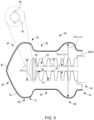
- the shaft 78 of plunger rod head 50 is specifically sized relative to the stopper 38 in order to reduce the impact/contribution that the plunger rod head 50 has on the radial stiffness of the stopper 38 when mated therewith.
- the shaft 78 of plunger rod head 50 is configured to have an outer diameter, OD head_shaft , that is reduced in magnitude as compared to a typical plunger rod head diameter in known plunger assemblies.
- existing plunger assembly designs include a "wide" plunger rod head configured to have an outer diameter that is similar in size to the cavity of the stopper, such that the plunger rod head substantially fills the cavity and increases the stiffness of the overall stopper/head combination - resulting in the stopper applying an increased radial force against the syringe barrel.
- This increased outwardly-directed radial force is applied by the rib(s) of the stopper 38 that are axially/longitudinally aligned with the cavity 74 and plunger rod head 50, such as at the second rib 68 of stopper 38, with the result being that the second rib 68 applies a greater radial force than the first rib 66.
- the ratio, R, of the outer diameter of the shaft 78 of plunger rod head 50, OD head_shaft , to the outer diameter of the stopper 38 at the second (proximal) rib 68, OD rib_prox is controlled so that R is equal to or less than 0.40 (R ⁇ 0.4) and preferably equal to or less than 0.3 (R ⁇ 0.3).
- the outer diameter of the stopper 38 at the second rib 68, OD rib_prox will be a set/standardized value that is determined by the volume of the syringe barrel (e.g., a 1-3 mL syringe, 5 mL syringe, 10 mL syringe, etc.), the outer diameter of the shaft 78 of plunger rod head 50, OD head_shaft , will be controlled/reduced in order to achieve a desired ratio, R.
- exemplary outer diameters for each of the shaft 78 and second rib 68 for various well-known syringe sizes/volumes - with the diameter of the shaft selected to provide a ratio, R, at or below a desired value. While diameter values for a 1-3 mL syringe, a 5 mL syringe, a 10 mL syringe, and a 50 mL syringe are set forth below, it is recognized that aspects of the disclosure extend to all syringes volumes from 0.5 to 50 mL.
- the decrease in radial stress provided by controlling of the ratio, R, should lead to a similar decrease in gliding force during advancement of the stopper 38 through the syringe barrel 12, assuming the same contact surface and friction coefficient (as it is understood that determining the gliding force also depends on the number of ribs, the interference level, the friction coefficient, and the contact surface).
- embodiments of the invention thus are directed to a plunger assembly having a stopper and plunger rod head may be configured to achieve a desired contact pressure and gliding force between the stopper and syringe barrel.
- a shaft of the plunger rod head has a diameter that is specifically sized relative to the outer diameter of the stopper at a proximal rib thereof (at a region containing an inner cavity of the stopper) in order to reduce the impact/contribution that the plunger rod head has on the radial stiffness of the stopper when mated therewith - with a ratio of the shaft outer diameter to the proximal rib outer diameter being kept below an identified value to control the contact pressure applied by the proximal rib to the syringe barrel.
Landscapes
- Health & Medical Sciences (AREA)
- Vascular Medicine (AREA)
- Engineering & Computer Science (AREA)
- Anesthesiology (AREA)
- Biomedical Technology (AREA)
- Heart & Thoracic Surgery (AREA)
- Hematology (AREA)
- Life Sciences & Earth Sciences (AREA)
- Animal Behavior & Ethology (AREA)
- General Health & Medical Sciences (AREA)
- Public Health (AREA)
- Veterinary Medicine (AREA)
- Infusion, Injection, And Reservoir Apparatuses (AREA)
Priority Applications (3)
| Application Number | Priority Date | Filing Date | Title |
|---|---|---|---|
| EP23306569.7A EP4527433A1 (fr) | 2023-09-21 | 2023-09-21 | Ensemble piston de seringue avec tête de tige de piston de diamètre réduit |
| CN202480060933.1A CN121889184A (zh) | 2023-09-21 | 2024-09-23 | 具有直径减小的柱塞杆头部的注射器柱塞组件 |
| PCT/EP2024/076595 WO2025062031A1 (fr) | 2023-09-21 | 2024-09-23 | Ensemble piston de seringue à tête de tige de piston d'injection à diamètre réduit |
Applications Claiming Priority (1)
| Application Number | Priority Date | Filing Date | Title |
|---|---|---|---|
| EP23306569.7A EP4527433A1 (fr) | 2023-09-21 | 2023-09-21 | Ensemble piston de seringue avec tête de tige de piston de diamètre réduit |
Publications (1)
| Publication Number | Publication Date |
|---|---|
| EP4527433A1 true EP4527433A1 (fr) | 2025-03-26 |
Family
ID=88315875
Family Applications (1)
| Application Number | Title | Priority Date | Filing Date |
|---|---|---|---|
| EP23306569.7A Pending EP4527433A1 (fr) | 2023-09-21 | 2023-09-21 | Ensemble piston de seringue avec tête de tige de piston de diamètre réduit |
Country Status (3)
| Country | Link |
|---|---|
| EP (1) | EP4527433A1 (fr) |
| CN (1) | CN121889184A (fr) |
| WO (1) | WO2025062031A1 (fr) |
Citations (2)
| Publication number | Priority date | Publication date | Assignee | Title |
|---|---|---|---|---|
| US20160243308A1 (en) * | 2013-10-07 | 2016-08-25 | Sio2 Medical Products, Inc. | Convertible plungers, film coated plungers and related syringe assemblies |
| WO2022109250A1 (fr) * | 2020-11-20 | 2022-05-27 | W. L. Gore & Associates, Inc. | Bouchons et procédés pour leur translation à travers un tube |
-
2023
- 2023-09-21 EP EP23306569.7A patent/EP4527433A1/fr active Pending
-
2024
- 2024-09-23 CN CN202480060933.1A patent/CN121889184A/zh active Pending
- 2024-09-23 WO PCT/EP2024/076595 patent/WO2025062031A1/fr active Pending
Patent Citations (2)
| Publication number | Priority date | Publication date | Assignee | Title |
|---|---|---|---|---|
| US20160243308A1 (en) * | 2013-10-07 | 2016-08-25 | Sio2 Medical Products, Inc. | Convertible plungers, film coated plungers and related syringe assemblies |
| WO2022109250A1 (fr) * | 2020-11-20 | 2022-05-27 | W. L. Gore & Associates, Inc. | Bouchons et procédés pour leur translation à travers un tube |
Also Published As
| Publication number | Publication date |
|---|---|
| WO2025062031A1 (fr) | 2025-03-27 |
| CN121889184A (zh) | 2026-04-17 |
Similar Documents
| Publication | Publication Date | Title |
|---|---|---|
| US10960139B2 (en) | Syringe assembly having a rotatably advanceable plunger rod | |
| AU714392B2 (en) | Syringe filling and delivery device | |
| US9101720B2 (en) | Prefilled syringe | |
| US6132400A (en) | Dual-chamber syringe and methods | |
| EP3513826B1 (fr) | Ensemble piston comprenant une tige de piston pour faire avancer un bouchon par l'intermédiaire d'une seringue | |
| US8888751B2 (en) | Slotted syringe | |
| CN109562226A (zh) | 注射器的密封结构和方法 | |
| KR20210068514A (ko) | 안전 주사기(safety syringe) | |
| EP2007452A1 (fr) | Seringue à mouvement séquentiel des collerettes du piston | |
| EP4527433A1 (fr) | Ensemble piston de seringue avec tête de tige de piston de diamètre réduit | |
| EP4529938A1 (fr) | Tige de piston de seringue avec raccord fileté à diamètre variable | |
| EP4454684A1 (fr) | Bouchon de piston de seringue sans pfas avec région incurvée inter-ruban | |
| JP3294537B2 (ja) | バイアル及びアンプルからの流体にアクセスする流体移送装置及びその装置を使用して流体を移送する方法 | |
| EP4613300A1 (fr) | Bouchon de piston de seringue à faible lubrification avec contact de surface de cylindre de seringue amélioré | |
| EP4681748A1 (fr) | Tige de piston de seringue avec contact de corps d'extrémité distale | |
| WO2024223848A1 (fr) | Bouchon de piston de seringue sans pfas avec région inter-nervure incurvée | |
| EP4617179A1 (fr) | Système d'outil de butée et procédé à centrage de butée amélioré pour une installation dans un cylindre de seringue | |
| WO2025212555A1 (fr) | Bouchon de piston de seringue avec cavité interne permettant le guidage | |
| WO2026006696A1 (fr) | Bouchon de piston de seringue à deux nervures avec élément de guidage axial | |
| EP4736911A1 (fr) | Procédé de fabrication d'une seringue préremplie pour réduire la force de glissement dans celle-ci | |
| WO2025080782A1 (fr) | Tige de piston de seringue à déconnexion simplifiée du bouchon | |
| WO2025064620A1 (fr) | Système d'outil de bouchage et méthode de chargement distal de bouchon pour installation dans un cylindre de seringue | |
| WO2026096156A1 (fr) | Procédé de fabrication d'une seringue pré-remplie pour réduire la force de glissement interne | |
| WO2024242865A1 (fr) | Système d'outil de bouchage pour installer un bouchon à valve dans un cylindre de seringue | |
| MXPA97004884A (es) | Un reten secuencial |
Legal Events
| Date | Code | Title | Description |
|---|---|---|---|
| PUAI | Public reference made under article 153(3) epc to a published international application that has entered the european phase |
Free format text: ORIGINAL CODE: 0009012 |
|
| STAA | Information on the status of an ep patent application or granted ep patent |
Free format text: STATUS: THE APPLICATION HAS BEEN PUBLISHED |
|
| AK | Designated contracting states |
Kind code of ref document: A1 Designated state(s): AL AT BE BG CH CY CZ DE DK EE ES FI FR GB GR HR HU IE IS IT LI LT LU LV MC ME MK MT NL NO PL PT RO RS SE SI SK SM TR |
|
| STAA | Information on the status of an ep patent application or granted ep patent |
Free format text: STATUS: REQUEST FOR EXAMINATION WAS MADE |
|
| 17P | Request for examination filed |
Effective date: 20250925 |