EP4525191A2 - Ccs-anordnung und batteriemodul - Google Patents
Ccs-anordnung und batteriemodul Download PDFInfo
- Publication number
- EP4525191A2 EP4525191A2 EP24199632.1A EP24199632A EP4525191A2 EP 4525191 A2 EP4525191 A2 EP 4525191A2 EP 24199632 A EP24199632 A EP 24199632A EP 4525191 A2 EP4525191 A2 EP 4525191A2
- Authority
- EP
- European Patent Office
- Prior art keywords
- extension portion
- bars
- connection part
- insulating film
- ccs
- Prior art date
- Legal status (The legal status is an assumption and is not a legal conclusion. Google has not performed a legal analysis and makes no representation as to the accuracy of the status listed.)
- Pending
Links
Images



Classifications
-
- H—ELECTRICITY
- H01—ELECTRIC ELEMENTS
- H01M—PROCESSES OR MEANS, e.g. BATTERIES, FOR THE DIRECT CONVERSION OF CHEMICAL ENERGY INTO ELECTRICAL ENERGY
- H01M50/00—Constructional details or processes of manufacture of the non-active parts of electrochemical cells other than fuel cells, e.g. hybrid cells
- H01M50/50—Current conducting connections for cells or batteries
- H01M50/502—Interconnectors for connecting terminals of adjacent batteries; Interconnectors for connecting cells outside a battery casing
- H01M50/519—Interconnectors for connecting terminals of adjacent batteries; Interconnectors for connecting cells outside a battery casing comprising printed circuit boards [PCB]
-
- H—ELECTRICITY
- H01—ELECTRIC ELEMENTS
- H01M—PROCESSES OR MEANS, e.g. BATTERIES, FOR THE DIRECT CONVERSION OF CHEMICAL ENERGY INTO ELECTRICAL ENERGY
- H01M10/00—Secondary cells; Manufacture thereof
- H01M10/42—Methods or arrangements for servicing or maintenance of secondary cells or secondary half-cells
- H01M10/425—Structural combination with electronic components, e.g. electronic circuits integrated to the outside of the casing
-
- H—ELECTRICITY
- H01—ELECTRIC ELEMENTS
- H01M—PROCESSES OR MEANS, e.g. BATTERIES, FOR THE DIRECT CONVERSION OF CHEMICAL ENERGY INTO ELECTRICAL ENERGY
- H01M10/00—Secondary cells; Manufacture thereof
- H01M10/42—Methods or arrangements for servicing or maintenance of secondary cells or secondary half-cells
- H01M10/48—Accumulators combined with arrangements for measuring, testing or indicating the condition of cells, e.g. the level or density of the electrolyte
- H01M10/482—Accumulators combined with arrangements for measuring, testing or indicating the condition of cells, e.g. the level or density of the electrolyte for several batteries or cells simultaneously or sequentially
-
- H—ELECTRICITY
- H01—ELECTRIC ELEMENTS
- H01M—PROCESSES OR MEANS, e.g. BATTERIES, FOR THE DIRECT CONVERSION OF CHEMICAL ENERGY INTO ELECTRICAL ENERGY
- H01M50/00—Constructional details or processes of manufacture of the non-active parts of electrochemical cells other than fuel cells, e.g. hybrid cells
- H01M50/20—Mountings; Secondary casings or frames; Racks, modules or packs; Suspension devices; Shock absorbers; Transport or carrying devices; Holders
- H01M50/204—Racks, modules or packs for multiple batteries or multiple cells
- H01M50/207—Racks, modules or packs for multiple batteries or multiple cells characterised by their shape
- H01M50/209—Racks, modules or packs for multiple batteries or multiple cells characterised by their shape adapted for prismatic or rectangular cells
-
- H—ELECTRICITY
- H01—ELECTRIC ELEMENTS
- H01M—PROCESSES OR MEANS, e.g. BATTERIES, FOR THE DIRECT CONVERSION OF CHEMICAL ENERGY INTO ELECTRICAL ENERGY
- H01M50/00—Constructional details or processes of manufacture of the non-active parts of electrochemical cells other than fuel cells, e.g. hybrid cells
- H01M50/50—Current conducting connections for cells or batteries
- H01M50/502—Interconnectors for connecting terminals of adjacent batteries; Interconnectors for connecting cells outside a battery casing
- H01M50/503—Interconnectors for connecting terminals of adjacent batteries; Interconnectors for connecting cells outside a battery casing characterised by the shape of the interconnectors
-
- H—ELECTRICITY
- H01—ELECTRIC ELEMENTS
- H01M—PROCESSES OR MEANS, e.g. BATTERIES, FOR THE DIRECT CONVERSION OF CHEMICAL ENERGY INTO ELECTRICAL ENERGY
- H01M50/00—Constructional details or processes of manufacture of the non-active parts of electrochemical cells other than fuel cells, e.g. hybrid cells
- H01M50/50—Current conducting connections for cells or batteries
- H01M50/502—Interconnectors for connecting terminals of adjacent batteries; Interconnectors for connecting cells outside a battery casing
- H01M50/507—Interconnectors for connecting terminals of adjacent batteries; Interconnectors for connecting cells outside a battery casing comprising an arrangement of two or more busbars within a container structure, e.g. busbar modules
-
- H—ELECTRICITY
- H01—ELECTRIC ELEMENTS
- H01M—PROCESSES OR MEANS, e.g. BATTERIES, FOR THE DIRECT CONVERSION OF CHEMICAL ENERGY INTO ELECTRICAL ENERGY
- H01M50/00—Constructional details or processes of manufacture of the non-active parts of electrochemical cells other than fuel cells, e.g. hybrid cells
- H01M50/50—Current conducting connections for cells or batteries
- H01M50/502—Interconnectors for connecting terminals of adjacent batteries; Interconnectors for connecting cells outside a battery casing
- H01M50/514—Methods for interconnecting adjacent batteries or cells
- H01M50/516—Methods for interconnecting adjacent batteries or cells by welding, soldering or brazing
-
- H—ELECTRICITY
- H01—ELECTRIC ELEMENTS
- H01M—PROCESSES OR MEANS, e.g. BATTERIES, FOR THE DIRECT CONVERSION OF CHEMICAL ENERGY INTO ELECTRICAL ENERGY
- H01M50/00—Constructional details or processes of manufacture of the non-active parts of electrochemical cells other than fuel cells, e.g. hybrid cells
- H01M50/50—Current conducting connections for cells or batteries
- H01M50/502—Interconnectors for connecting terminals of adjacent batteries; Interconnectors for connecting cells outside a battery casing
- H01M50/521—Interconnectors for connecting terminals of adjacent batteries; Interconnectors for connecting cells outside a battery casing characterised by the material
- H01M50/522—Inorganic material
-
- H—ELECTRICITY
- H01—ELECTRIC ELEMENTS
- H01M—PROCESSES OR MEANS, e.g. BATTERIES, FOR THE DIRECT CONVERSION OF CHEMICAL ENERGY INTO ELECTRICAL ENERGY
- H01M50/00—Constructional details or processes of manufacture of the non-active parts of electrochemical cells other than fuel cells, e.g. hybrid cells
- H01M50/50—Current conducting connections for cells or batteries
- H01M50/569—Constructional details of current conducting connections for detecting conditions inside cells or batteries, e.g. details of voltage sensing terminals
-
- H—ELECTRICITY
- H01—ELECTRIC ELEMENTS
- H01M—PROCESSES OR MEANS, e.g. BATTERIES, FOR THE DIRECT CONVERSION OF CHEMICAL ENERGY INTO ELECTRICAL ENERGY
- H01M50/00—Constructional details or processes of manufacture of the non-active parts of electrochemical cells other than fuel cells, e.g. hybrid cells
- H01M50/50—Current conducting connections for cells or batteries
- H01M50/572—Means for preventing undesired use or discharge
- H01M50/584—Means for preventing undesired use or discharge for preventing incorrect connections inside or outside the batteries
- H01M50/588—Means for preventing undesired use or discharge for preventing incorrect connections inside or outside the batteries outside the batteries, e.g. incorrect connections of terminals or busbars
-
- H—ELECTRICITY
- H01—ELECTRIC ELEMENTS
- H01M—PROCESSES OR MEANS, e.g. BATTERIES, FOR THE DIRECT CONVERSION OF CHEMICAL ENERGY INTO ELECTRICAL ENERGY
- H01M50/00—Constructional details or processes of manufacture of the non-active parts of electrochemical cells other than fuel cells, e.g. hybrid cells
- H01M50/50—Current conducting connections for cells or batteries
- H01M50/572—Means for preventing undesired use or discharge
- H01M50/584—Means for preventing undesired use or discharge for preventing incorrect connections inside or outside the batteries
- H01M50/59—Means for preventing undesired use or discharge for preventing incorrect connections inside or outside the batteries characterised by the protection means
- H01M50/593—Spacers; Insulating plates
-
- H—ELECTRICITY
- H01—ELECTRIC ELEMENTS
- H01M—PROCESSES OR MEANS, e.g. BATTERIES, FOR THE DIRECT CONVERSION OF CHEMICAL ENERGY INTO ELECTRICAL ENERGY
- H01M2200/00—Safety devices for primary or secondary batteries
- H01M2200/10—Temperature sensitive devices
- H01M2200/105—NTC
-
- H—ELECTRICITY
- H01—ELECTRIC ELEMENTS
- H01M—PROCESSES OR MEANS, e.g. BATTERIES, FOR THE DIRECT CONVERSION OF CHEMICAL ENERGY INTO ELECTRICAL ENERGY
- H01M2220/00—Batteries for particular applications
- H01M2220/20—Batteries in motive systems, e.g. vehicle, ship, plane
-
- Y—GENERAL TAGGING OF NEW TECHNOLOGICAL DEVELOPMENTS; GENERAL TAGGING OF CROSS-SECTIONAL TECHNOLOGIES SPANNING OVER SEVERAL SECTIONS OF THE IPC; TECHNICAL SUBJECTS COVERED BY FORMER USPC CROSS-REFERENCE ART COLLECTIONS [XRACs] AND DIGESTS
- Y02—TECHNOLOGIES OR APPLICATIONS FOR MITIGATION OR ADAPTATION AGAINST CLIMATE CHANGE
- Y02E—REDUCTION OF GREENHOUSE GAS [GHG] EMISSIONS, RELATED TO ENERGY GENERATION, TRANSMISSION OR DISTRIBUTION
- Y02E60/00—Enabling technologies; Technologies with a potential or indirect contribution to GHG emissions mitigation
- Y02E60/10—Energy storage using batteries
Definitions
- the present disclosure relates to the technical field of batteries, and in particular, to a cells contact system (CCS) assembly and a battery module.
- CCS cells contact system
- a CCS assembly of a cylindrical power battery module generally includes two output bars and a plurality of connecting bars arranged between the two output bars.
- the connecting bar includes a plurality of conductive units, and each conductive unit includes a positive part and a negative part connected with each other.
- the conductive unit is configured to connect adjacent battery cells in series. Specifically, the positive part of the conductive unit is connected to a positive pole terminal of one battery cell, and the negative part of the same conductive unit is connected to a negative pole terminal of the other battery cell.
- the plurality of connecting bars are arranged along a length direction of the battery module. In order to integrate the CCS assembly, the output bars and the connecting bars are generally integrated on a plastic bracket.
- the present disclosure aims to solve the following technical problems: How to reduce the production costs of the CCS assembly, and how to enhance the strength or stiffness of the CCS assembly to facilitate subsequent transportation and processing of the CCS assembly.
- the present disclosure provides a CCS assembly applied to a battery module.
- the CCS assembly includes an insulating film and a busbar group.
- the busbar group includes two output bars, a plurality of connecting bars, and two positioning plates.
- the two output bars are correspondingly arranged at two ends of the battery module in a length direction, and the connecting bars are arranged between the two output bars.
- the output bar is at least partially supported by the positioning plate that is correspondingly arranged.
- the positioning plate extends toward the connecting bar adjacent to the corresponding output bar.
- the insulating film is disposed on one side of the busbar group facing battery cells of the battery module.
- the busbar group is connected to the insulating film.
- the present disclosure provides a battery module, including battery cells and the above-mentioned CCS assembly.
- the battery cells pass through the insulating film and the positioning plates to connect with the busbar groups.
- the present disclosure integrates the busbar group (i.e. the output bars, the connecting bars, and the positioning plates) on the insulating film, which may effectively reduce the production costs. Moreover, the insulating film is easy to cut, so it is easy to control the processing accuracy when the insulating film is applied in the battery module with a long-length, facilitates the arrangement and adjustment of the busbar group, and has low processing difficulty.
- the busbar group i.e. the output bars, the connecting bars, and the positioning plates
- the positioning plates of the present disclosure are located at both ends of the CCS assembly in the length direction of the battery module, which may provide auxiliary support to the CCS assembly, enhance the strength or stiffness of the CCS assembly to a certain extent, and facilitate subsequent transportation and processing of the CCS assembly.
- the insulating film provided on the side of the busbar group facing the battery cells may effectively insulate the busbar group and the battery cells to prevent short circuits of the battery cells.
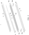
- a CCS assembly 1 includes an insulating film 4 and a busbar group.
- the busbar group includes output bars, connecting bars 10c, and positioning plates.
- two output bars are correspondingly arranged at two ends of a battery module in a length direction (that is, a length direction a of the CCS assembly 1).
- a plurality of connecting bars 10c are arranged between the two output bars.
- the output bar is at least partially supported by one corresponding positioning plate, and the positioning plate extends toward the connecting bar 10c adjacent to the corresponding output bar.
- the insulating film 4 is disposed on one side of the busbar group facing battery cells 20 of the battery module.
- the busbar group is connected to the insulating film 4. That is, the output bars, the connecting bars 10c, and the positioning plates are all connected to the insulating film 4.
- the insulating film 4 is easy to cut, so it is easy to control the processing accuracy when the insulating film is applied in the battery module with a long-length, facilitates the arrangement and adjustment of the busbar group, and has low processing difficulty.
- the positioning plates here are located at the two ends of the CCS assembly 1 in the length direction of the battery module, which may provide auxiliary support to the CCS assembly 1, enhance the strength or stiffness of the CCS assembly 1 to a certain extent, and facilitate subsequent transportation and processing of the CCS assembly 1.
- the insulating film 4 provided on the side of the busbar group facing the battery cells 20 may effectively insulate the busbar group and the battery cells 20 to prevent short circuits of the battery cells 20.
- the output bars include a positive output bar 10b and a negative output bar 10a.
- the positive output bar 10b is located at a positive output end of the battery module
- the negative output bar 10a is located at a negative output end of the battery module.
- the output bar is provided with the same number of connecting pieces as conductive units 13 constituting one single connecting bar 10c.
- the connecting piece of the negative output bar 10a is a negative connecting piece 123a configured to connect with a negative pole terminal 202 of one battery cell 20 which is located at at the negative output end of the battery module.
- the connecting piece of the positive output bar 10b is positive connecting piece 123b configured to connect with a positive pole terminal 201 of one battery cell 20 which is located at the positive output end of the battery module.
- the positioning plate is a plastic plate.
- the insulating film 4 includes but is not limited to hot melt adhesive film.
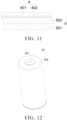
- the insulating film 4 includes a base film 401 and an adhesive layer 402, and the adhesive layer 402 is disposed on one side facing the busbar group.
- the base film 401 layer may be made of polyethylene terephthalate (PET).
- PET polyethylene terephthalate
- a thickness of the base film 401 is D 1, where 0 ⁇ m ⁇ D1 ⁇ 150 ⁇ m.
- a thickness of the adhesive layer 402 is D2, where 0 ⁇ m ⁇ D2 ⁇ 50 ⁇ m.
- the busbar group is bonded or thermally pressed with the insulating film 4. In some embodiments, the busbar group and the insulating film 4 are thermally pressed together.
- the output bar includes an inner connection part 12 and an outer connection part 11 connected with each other.
- the outer connection part 11 and the inner connection part 12 are separate parts.
- a thickness of the outer connection part 11 is greater than a thickness of the inner connection part 12.
- the positioning plate abuts against a side surface of the inner connection part 12 facing the battery cells 20 in its thickness direction.
- the positioning plate abutting the inner connection part 12 can support the thin inner connection part 12, improve the structural strength of the inner connection part 12, and effectively prevent the inner connection part 12 from being damaged during the transportation of the CCS assembly 1.
- the output bar composed of separate parts including the outer connection part 11 and the inner connection part 12 has simple processing technology and low production costs.
- the structural design in which the thickness of the outer connection part 11 is greater than the thickness of the inner connection part 12 may effectively improve the structural strength of the output bar, thereby improving the reliability of the connection structure between the modules when they are connected in series.
- the inner connection part 12 with the small thickness is convenient for welding with the battery cells 20, while the outer connection part 11 with a large thickness may ensure the flow capacity of the output bar.
- the inner connection part 12 is integrally stamped and formed.
- the inner connection part 12 and the outer connection part 11 are welded.
- the connecting piece is a part of the inner connection part 12.
- the inner connection part 12 includes a main portion 121 connected to the outer connection part 11.
- One or more extension portions 122 are provided on one side of the main portion 121 away from the outer connection part 11.
- the extension portion 122 is configured to connect with the positive pole terminal 201 or the negative pole terminal 202 of one battery cell 20.
- the positioning plate abuts against the extension portions 122.
- a free end of the extension portion 122 of the positive output bar 10b is connected to the positive pole terminal 201 of one battery cell 20, and a free end of the extension portion 122 of the negative output bar 10a is connected to the negative pole terminal 202 of one battery cell 20.
- the extension portion 122 is a part of the inner connection part 12.
- An extending direction of the extension portion 122 here is parallel to an extending direction of the main portion 121, and the extension portions 122 are connected to the main portion 121 by a bending portion 124. Furthermore, the main portion 121, the bending portion 124, and the one or more extension portions 122 are integrated to together form the inner connection part 12.
- the outer connection part 11 is provided in an area corresponding to the main portion 121. The outer connection part 11 may increase the structural strength of the main portion 121, and the positioning plate abutting the extension portions 122 may increase the structural strength of the extension portions 122. Thus, the structural strength of inner connection part 12 may be improved as a whole, and the flow capacity of the output bar may be improved at the same time.
- the structural arrangement of the positioning plate abutting against the extension portions 122 may balance the structural strength of each area of the inner connection part 12 on the basis of increasing the structural strength of the main portion 121 of the outer connection part 11.
- a number of the extension portions 122 is equal to a number of the connecting pieces, and the connecting pieces are arranged in one-to-one correspondence at ends of the extension portions 122 away from the outer connection part 11.
- the connecting piece serves as a free end of the corresponding extension portion 122.
- the positioning plate may also be attached to and extend along the side surface of the inner connection part 12 facing the battery cells 20, and the positioning plate at least partially abuts the extension portions 122, the bending portion 124, and the main portion 121.
- the positioning plate is disposed between the extension portion 122 and the battery cell 20.
- the positioning plate includes a motherboard 31.
- a connecting protrusion 32 is provided on a side surface of the motherboard 31 facing the extension portion 122.
- the connecting protrusion 32 supports the extension portion 122.
- the connecting protrusion 32 is disposed away from the free end of the extension portion 122 in the extending direction of the extension portion 122. That is, the connecting protrusion 32 is disposed on one lateral side of the extension portion 122 close to the outer connection part 11. In other words, a root of the extension portion 122 is supported by the connecting protrusion 32.
- Such arrangement allows a position of the positioning plate supporting the extension portion 122 closer to the outer connection part 11, thereby preventing excessive support of the positioning plate on the extension portion 122, which may weaken the ability of the extension portion 122 to bend towards or away from the battery cells 20. That is, the structural design provided on the side of the connecting protrusion 32 close to the outer connection part 11 may support the extension portion 122 to enhance its structural strength without affecting its deformation ability toward or away from the battery cells 20, which is convenient for subsequent connection between the extended portion 122 and the battery cell 20, avoiding false welding between the extended portion 122 and the battery cell 20.
- the embodiments provide a negative positioning plate 30a and a positive positioning plate 30b. They have the same function, and their shapes may be designed according to shapes of the negative output bar 10a and the positive output bar 10b, no specific restrictions are made here. It should be noted that the positive positioning plate 30b is located on one side of the positive output bar 10b, and the negative positioning plate 30a is located on one side of the negative output bar 10a.
- the motherboard 31 is provided with one or more exposure holes 33, and each of the exposure holes 33 passes through the motherboard 31.
- the free end (i.e. the connecting piece) of the extension portion 122 is connected to the positive pole terminal 201 or the negative pole terminal 202 of one battery cell 20 through the exposure hole 33.
- the exposure hole 33 here is configured to expose the positive pole terminal 201 or the negative pole terminal 202 of one battery cell 20 adjacent to the output bar, and the exposure hole 33 is arranged corresponding to one second welding hole 41 on the insulating film 4 close to the output bar.
- the busbar group may be provided with insulating films 4 on both sides facing and facing away from the battery cells 20.
- the CCS assembly 1 further includes a signal acquisition component connected to the busbar group. Specifically, input terminals of the signal acquisition component are arranged corresponding to the output bars and the connecting bars 10c.
- the signal acquisition component is located between the insulating film 4 and the busbar group.
- the insulating films 4 are provided on both sides of the busbar group in the thickness direction, which may further improve the structural strength of the CCS assembly 1 and improve the robustness of the output bars and the connecting bars 10c after they are laid out. It should be noted that, as illustrated in FIG. 2 and FIG.
- the two insulating films 4 over and below the busbar group are respectively provided with the second welding holes 41.
- the positive pole terminals 201 and the negative pole terminals 202 of the battery cells 20 are abutted to the output bars and the connecting bars 10c through the second welding holes 41 of the lower insulating film 4, and a welding gun is abutted to the output bars and the connecting bars 10c through the second welding holes 41 of the upper insulating film 4 to perform the welding operation.
- the signal acquisition component in the embodiments may be a flexible printed circuit (FPC) 5 or a signal acquisition wire harness.
- the signal acquisition component is the FPC 5.
- Athickness of the FPC 5 is thin, which is beneficial to reducing the thickness of the CCS assembly 1.
- the FPC 5 extends along a length direction of the battery module, input terminals of the FPC 5 are connected to the output bars and the connecting bars 10c to monitor voltages or temperature signals of the battery cells 20 corresponding to the output bars and the connecting bars 10c.
- Output terminals of the FPC 5 are arranged at one end of the battery module in the length direction and connected to a connector 6, which is configured to connect with a battery management system (BMS).
- BMS battery management system
- the signal acquisition component i.e. the FPC 5 is disposed on one side of the busbar group away from the battery cells 20. That is, the signal acquisition component is located between the busbar group and the upper insulating film 4.
- the FPC 5 includes a PI layer 501 and a substrate layer 502 stacked on the PI layer 501.
- the substrate layer 502 is provided with collection nickel sheets 51 and a negative temperature coefficient thermistor (NTC) 52 to form the input terminals of the signal acquisition component.
- NTC negative temperature coefficient thermistor
- the PI layer 501 is disposed between the substrate layer 502 and the busbar group, and the substrate layer 502 is disposed between the PI layer 501 and the insulating film 4 bonded to the FPC 5. As illustrated in FIG. 3 and FIG.
- the insulating film 4 (the upper insulating film 4 in the embodiments) here may serve as another PI layer 501 stacked on the substrate layer 502 (a conventional FPC 5 includes at least two PI layer 501, and the substrate layer 502 is sandwiched between two PI layers 501). That is, the PI layer 501, the substrate layer 502, and the upper insulating film 4 stacked sequentially from bottom to top constitute a complete FPC 5, which may reduce the costs of the FPC 5, effectively protect the FPC 5 and the NTC 52, reduce the thickness of the FPC 5, reduce the thickness of the CCS assembly 1, and improve an integration rate of the CCS assembly 1.
- the FPC 5 may also be disposed on the side of the busbar group facing the battery cells 20. Accordingly, the insulating film 4 (the lower insulating film 4) disposed close to the battery cells 20 serves as a part of the FPC 5, as described above, will not be repeated here.
- first welding holes 43 corresponding to the collection nickel sheets 51 are defined on the insulating films 4 to expose the collection nickel sheets 51.
- the collection nickel sheets 51 contact the output bars and connecting bars 10c through the first welding holes 43 of the lower insulating film 4, and the welding gun contacts the collection nickel sheets 51 through the first welding holes 43 of the upper insulating film 4 to weld the collection nickel sheets 51 with the output bars.
- the motherboard 31 is provided with first positioning holes 34 passing through the motherboard 31, the insulating films 4 are provided with second positioning holes 42, and the output bars are provided with third positioning holes 125.
- the first positioning hole 34, the second positioning hole 42, and the third positioning hole 125 are arranged correspondingly.
- the first positioning hole 34 is coaxial with its corresponding second positioning hole 42 and third positioning hole 125.
- the first positioning holes 34, the second positioning holes 42, and the third positioning holes 125 are configured for the positioning assembly of the insulating films 4, the output bars, and the positioning plates, which is conducive to improving the assembly accuracy of CCS assembly 1.
- a first fillet 321 is provided on an outer edge of the connecting protrusion 32 away from the free end of the extension portion 122.
- top corners of outer edges of the motherboard 31 close to the free end of the extension portion 122 are provided with second fillets 311.
- the first fillet 321 here is configured to reduce the stress concentration on the outer edge of the connecting protrusion 32 toward the bending portion 124, which facilitates the positioning plate demoulding and prevents the output bars from being damaged when the output bars are assembled.
- the second fillets 311 are configured to reduce the stress concentration on the top corners (i.e. the side of the positioning plate away from the outer connection part 11) of the motherboard 31, thereby preventing other components of the CCS assembly 1 from being scratched during the assembly process.
- the connecting bars 10c is supported by the positioning plate. Specifically, a portion of the positioning plate extending toward the connecting bar 10c adjacent to the corresponding output bar, that is, the motherboard 31, may also provide support for the connecting bar 10c, thereby further improving the structural strength of the CCS assembly 1.
- the motherboard 31 is provided with corresponding holes, so that the connecting bars 10c can pass through the motherboard 31 and be connected to the battery cells 20.
- the embodiments also provide a battery module.
- the battery module includes battery cells 20 and the aforementioned CCS assembly 1.
- the battery cells 20 pass through the insulating film 4 and the positioning plates and are connected to the busbar group.
- the battery module has high safety and low production costs.
Landscapes
- Chemical & Material Sciences (AREA)
- Chemical Kinetics & Catalysis (AREA)
- Electrochemistry (AREA)
- General Chemical & Material Sciences (AREA)
- Engineering & Computer Science (AREA)
- Manufacturing & Machinery (AREA)
- Inorganic Chemistry (AREA)
- Microelectronics & Electronic Packaging (AREA)
- Battery Mounting, Suspending (AREA)
- Connection Of Batteries Or Terminals (AREA)
Applications Claiming Priority (3)
| Application Number | Priority Date | Filing Date | Title |
|---|---|---|---|
| CN202311172580.8A CN117335100A (zh) | 2023-09-12 | 2023-09-12 | Ccs组件及电池模组 |
| CN202322477921.4U CN220856839U (zh) | 2023-09-12 | 2023-09-12 | Ccs组件及电池模组 |
| PCT/CN2024/088258 WO2025055326A1 (zh) | 2023-09-12 | 2024-04-17 | Ccs 组件及电池模组 |
Publications (2)
| Publication Number | Publication Date |
|---|---|
| EP4525191A2 true EP4525191A2 (de) | 2025-03-19 |
| EP4525191A3 EP4525191A3 (de) | 2025-06-04 |
Family
ID=92762407
Family Applications (1)
| Application Number | Title | Priority Date | Filing Date |
|---|---|---|---|
| EP24199632.1A Pending EP4525191A3 (de) | 2023-09-12 | 2024-09-11 | Ccs-anordnung und batteriemodul |
Country Status (2)
| Country | Link |
|---|---|
| US (1) | US20250087843A1 (de) |
| EP (1) | EP4525191A3 (de) |
Family Cites Families (6)
| Publication number | Priority date | Publication date | Assignee | Title |
|---|---|---|---|---|
| CN109103405A (zh) * | 2018-08-19 | 2018-12-28 | 江西赣锋电池科技有限公司 | 一种电池包母排、制备方法及电池包 |
| CN111430650B (zh) * | 2019-11-22 | 2022-02-25 | 蜂巢能源科技有限公司 | 电池包和车辆 |
| EP3872891A1 (de) * | 2020-02-27 | 2021-09-01 | Mersen France Angers SAS | Laminierte stromschiene für energiespeichervorrichtung |
| KR102735192B1 (ko) * | 2020-11-30 | 2024-11-27 | 삼성에스디아이 주식회사 | 배터리 팩 |
| EP4250464A4 (de) * | 2022-01-25 | 2024-05-15 | Eve Power Co., Ltd. | Sammelschienenanordnung und zylindrisches traktionsbatteriemodul |
| CN217934135U (zh) * | 2022-06-30 | 2022-11-29 | 瑞浦兰钧能源股份有限公司 | 一种ccs集成组件及电池模组 |
-
2024
- 2024-09-11 US US18/882,733 patent/US20250087843A1/en active Pending
- 2024-09-11 EP EP24199632.1A patent/EP4525191A3/de active Pending
Also Published As
| Publication number | Publication date |
|---|---|
| US20250087843A1 (en) | 2025-03-13 |
| EP4525191A3 (de) | 2025-06-04 |
Similar Documents
| Publication | Publication Date | Title |
|---|---|---|
| CN105745772B (zh) | 电源装置 | |
| EP3063822B1 (de) | Signalsammlungs- und stromverbindungsanordnung | |
| EP3764422A1 (de) | Abtastplatine für batteriemodul und batteriemodul | |
| CN110867552A (zh) | 电池保护板及电池组件 | |
| CN210006811U (zh) | 电池包的电芯组、电池包和车辆 | |
| CN112821002B (zh) | 电池模块及具有其的车辆 | |
| EP4243186A1 (de) | Sammelschiene, batteriezellenerfassungsanordnung und batteriemodul | |
| CN115579588A (zh) | 一种ffc-fpc组合式电池模组集成采集母排 | |
| CN114583398A (zh) | 一种汇流排、电芯采集组件及电池模组 | |
| CN117335100A (zh) | Ccs组件及电池模组 | |
| CN218182435U (zh) | 电池模组、电池包和车辆 | |
| EP4525191A2 (de) | Ccs-anordnung und batteriemodul | |
| CN116995369A (zh) | 采用吸塑工艺串接集成母排的电池组结构 | |
| CN218887464U (zh) | 电池信息采集组件及电池模组 | |
| CN212542630U (zh) | 采样结构以及电池模组 | |
| CN211088379U (zh) | 电池保护板及电池组件 | |
| US20240396180A1 (en) | Current collector | |
| CN221530198U (zh) | 一种电池模组 | |
| CN220628165U (zh) | Fpc采集装置及电池模组 | |
| CN221486588U (zh) | 电路板、电池组和装置 | |
| CN219371280U (zh) | 一种动力电池长模组用的采集组件 | |
| US20240072396A1 (en) | Battery module | |
| CN220856839U (zh) | Ccs组件及电池模组 | |
| CN112259921B (zh) | 一种电池模组的连接电路板 | |
| CN120527581B (zh) | 电池装置和用电装置 |
Legal Events
| Date | Code | Title | Description |
|---|---|---|---|
| PUAI | Public reference made under article 153(3) epc to a published international application that has entered the european phase |
Free format text: ORIGINAL CODE: 0009012 |
|
| STAA | Information on the status of an ep patent application or granted ep patent |
Free format text: STATUS: REQUEST FOR EXAMINATION WAS MADE |
|
| 17P | Request for examination filed |
Effective date: 20240911 |
|
| AK | Designated contracting states |
Kind code of ref document: A2 Designated state(s): AL AT BE BG CH CY CZ DE DK EE ES FI FR GB GR HR HU IE IS IT LI LT LU LV MC ME MK MT NL NO PL PT RO RS SE SI SK SM TR |
|
| PUAL | Search report despatched |
Free format text: ORIGINAL CODE: 0009013 |
|
| AK | Designated contracting states |
Kind code of ref document: A3 Designated state(s): AL AT BE BG CH CY CZ DE DK EE ES FI FR GB GR HR HU IE IS IT LI LT LU LV MC ME MK MT NL NO PL PT RO RS SE SI SK SM TR |
|
| RIC1 | Information provided on ipc code assigned before grant |
Ipc: H01M 50/519 20210101ALI20250429BHEP Ipc: H01M 50/507 20210101AFI20250429BHEP |