EP4524644A1 - Optical isolator - Google Patents
Optical isolator Download PDFInfo
- Publication number
- EP4524644A1 EP4524644A1 EP23803463.1A EP23803463A EP4524644A1 EP 4524644 A1 EP4524644 A1 EP 4524644A1 EP 23803463 A EP23803463 A EP 23803463A EP 4524644 A1 EP4524644 A1 EP 4524644A1
- Authority
- EP
- European Patent Office
- Prior art keywords
- polarizer
- optical isolator
- faraday rotator
- polarizers
- transmitted light
- Prior art date
- Legal status (The legal status is an assumption and is not a legal conclusion. Google has not performed a legal analysis and makes no representation as to the accuracy of the status listed.)
- Pending
Links
Images


Classifications
-
- G—PHYSICS
- G02—OPTICS
- G02B—OPTICAL ELEMENTS, SYSTEMS OR APPARATUS
- G02B27/00—Optical systems or apparatus not provided for by any of the groups G02B1/00 - G02B26/00, G02B30/00
- G02B27/28—Optical systems or apparatus not provided for by any of the groups G02B1/00 - G02B26/00, G02B30/00 for polarising
- G02B27/281—Optical systems or apparatus not provided for by any of the groups G02B1/00 - G02B26/00, G02B30/00 for polarising used for attenuating light intensity, e.g. comprising rotatable polarising elements
-
- G—PHYSICS
- G02—OPTICS
- G02F—OPTICAL DEVICES OR ARRANGEMENTS FOR THE CONTROL OF LIGHT BY MODIFICATION OF THE OPTICAL PROPERTIES OF THE MEDIA OF THE ELEMENTS INVOLVED THEREIN; NON-LINEAR OPTICS; FREQUENCY-CHANGING OF LIGHT; OPTICAL LOGIC ELEMENTS; OPTICAL ANALOGUE/DIGITAL CONVERTERS
- G02F1/00—Devices or arrangements for the control of the intensity, colour, phase, polarisation or direction of light arriving from an independent light source, e.g. switching, gating or modulating; Non-linear optics
- G02F1/01—Devices or arrangements for the control of the intensity, colour, phase, polarisation or direction of light arriving from an independent light source, e.g. switching, gating or modulating; Non-linear optics for the control of the intensity, phase, polarisation or colour
- G02F1/09—Devices or arrangements for the control of the intensity, colour, phase, polarisation or direction of light arriving from an independent light source, e.g. switching, gating or modulating; Non-linear optics for the control of the intensity, phase, polarisation or colour based on magneto-optical elements, e.g. exhibiting Faraday effect
- G02F1/093—Devices or arrangements for the control of the intensity, colour, phase, polarisation or direction of light arriving from an independent light source, e.g. switching, gating or modulating; Non-linear optics for the control of the intensity, phase, polarisation or colour based on magneto-optical elements, e.g. exhibiting Faraday effect used as non-reciprocal devices, e.g. optical isolators, circulators
-
- G—PHYSICS
- G02—OPTICS
- G02F—OPTICAL DEVICES OR ARRANGEMENTS FOR THE CONTROL OF LIGHT BY MODIFICATION OF THE OPTICAL PROPERTIES OF THE MEDIA OF THE ELEMENTS INVOLVED THEREIN; NON-LINEAR OPTICS; FREQUENCY-CHANGING OF LIGHT; OPTICAL LOGIC ELEMENTS; OPTICAL ANALOGUE/DIGITAL CONVERTERS
- G02F2201/00—Constructional arrangements not provided for in groups G02F1/00 - G02F7/00
- G02F2201/16—Constructional arrangements not provided for in groups G02F1/00 - G02F7/00 series; tandem
Definitions
- the present invention relates to an optical isolator.
- an optical isolator which includes a Faraday rotator to rotate a plane of polarization in a non-reciprocal manner.
- Patent Document 1 JP H02-272419 A
- LD laser diode
- SOA semiconductor amplifier
- An optical isolator with a 1.5-stage construction (three polarizers and two Faraday rotators, also referred to as 1.5-stage optical isolator) provides higher light-blocking performance than an optical isolator with a single-stage construction (two polarizers and one Faraday rotator, also referred to as single-stage optical isolator), but its blocking performance has been dependent on extinction performance of the polarizer at the center.
- the present invention was made to solve the above problem and an object of the present invention is to provide an optical isolator having high light-blocking performance.
- the present invention was made to achieve the above object and provides an optical isolator with multiple stages.
- the optical isolator includes: an optical element including at least a first polarizer, a first Faraday rotator, a second polarizer, a third polarizer, a second Faraday rotator, and a fourth polarizer in sequence in a direction in which light travels; and at least one permanent magnet configured to apply a magnetic field to the first Faraday rotator and the second Faraday rotator.
- a relative angle between a transmitted light polarization axis of the second polarizer and a transmitted light polarization axis of the third polarizer is equal to or more than 0.1 degrees.
- the optical isolator with such a configuration has high light-blocking performance.
- the first polarizer, the first Faraday rotator, and the second polarizer may be integrated, and the third polarizer, the second Faraday rotator, and the fourth polarizer may be integrated.
- This configuration provides an optical isolator with a smaller size.
- the second polarizer and the third polarizer may be flat-plate polarizers.
- the present invention can provide an optical isolator having high light-blocking performance.
- an optical isolator having high light-blocking performance can be provided by an optical isolator with multiple stages that includes: an optical element including at least a first polarizer, a first Faraday rotator, a second polarizer, a third polarizer, a second Faraday rotator, and a fourth polarizer in sequence in a direction in which light travels; and at least one permanent magnet configured to apply a magnetic field to the first Faraday rotator and the second Faraday rotator, in which a relative angle between a transmitted light polarization axis of the second polarizer and a transmitted light polarization axis of the third polarizer is equal to or more than 0.1 degrees.
- the dual-stage optical isolator 100A includes an optical element 10 having a first polarizer 1, a first Faraday rotator 13, a second polarizer 2, a third polarizer 3, a second Faraday rotator 14, and a fourth polarizer 4 in sequence in a forward direction (direction in which light travels), a permanent magnet 11 to apply a magnetic field to the first Faraday rotator 13, and a permanent magnet 12 to apply a magnetic field to the second Faraday rotator 14.
- first polarizer 1 illustrates an example in which a section including a first stage of the optical element 10 (first polarizer 1, first Faraday rotator 13, second polarizer 2) and the permanent magnet 11 is separate from a section including a second stage of the optical element 10 (third polarizer 3, second Faraday rotator 14, fourth polarizer 4) and the permanent magnet 12.
- the first stage and the second stage illustrated in FIG. 1 may be integrated to make an integrated, dual-stage optical isolator 100B as illustrated in FIG. 2 .
- the optical isolator may include a single permanent magnet 15 as a permanent magnet that applies a magnetic field to the first Faraday rotator 13 and the second Faraday rotator 14.
- Such an optical isolator can be reduced in size because the gap between the second polarizer and the third polarizer is eliminated.
- polarizers, Faraday rotators and permanent magnets can be employed as appropriate for the first polarizer, the first Faraday rotator, the second polarizer, the third polarizer, the second Faraday rotators, the fourth polarizer, and the permanent magnet.
- (TbEuBi) 3 (FeGa) 5 O 12 or (GdBi) 3 (FeGa) 5 O 12 can be used for the Faraday rotators.
- the dual-stage optical isolator has been described above as an example, a multi-stage optical isolator with more than two stages can be employed.
- the relative angle ⁇ between the transmitted light polarization axis of the second polarizer 2 and the transmitted light polarization axis of the third polarizer 3 is equal to or more than 0.1 degrees.
- the relative angle ⁇ between the transmitted light polarization axis 5 of the second polarizer 2 and the transmitted light polarization axis 6 of the third polarizer 3 can be adjusted by rotating the second polarizer 2 and the third polarizer 3 relative to each other while keeping them parallel.
- the second polarizer and the third polarizer are preferably flat-plate polarizers.
- the relative angle ⁇ between the transmitted light polarization axes can be set more stably.
- FIG. 8 illustrates an example of backward insertion loss of the dual-stage optical isolator and wavelength dependence of extinction performance of the second and third polarizers.
- the backward insertion loss of the optical isolator calculated from the wavelength dependence of the Faraday rotation angle of the Faraday rotator used is as indicated by a dash-dot line in FIG. 8 .
- the extinction performance of polarizers is finite, and the extinction performance of the second and third polarizers has the characteristic as indicated by the dotted line relative to the optical wavelength.
- FIG. 4 and FIG. 5 illustrate a relationship between the relative angle ⁇ between the transmitted light polarization axes of the second and third polarizers and the backward insertion loss of the optical isolator.
- the extinction performance of the polarizer (dotted line) is also illustrated.
- FIG. 4 illustrates the relative angle ⁇ in the range of 0 to 14 degrees (°)
- FIG. 4 illustrates the relative angle ⁇ in the range of 0 to 14 degrees (°)
- FIG. 5 is an enlarged illustration of the relative angle ⁇ from 0 to 2 degrees (°).
- the relative angle ⁇ between the transmitted light polarization axes of the second and third polarizers is gradually increased from 0.0 degrees (°)
- the backward insertion loss of the optical isolator increases away from the extinction performance of the polarizers and exhibits a greater value.
- the relative angle between the transmitted light polarization axes acts to allow each of the polarizers to have an independent function.
- the second and third polarizers function integrally and consequently exhibit the same behavior as a 1.5-stage optical isolator (three polarizers, two Faraday rotators), and there is a strong dependence on the performance of the polarizers.
- the upper limit of the relative angle ⁇ between the transmitted light polarization axes of the second and third polarizers is not limited, but the upper limit of the relative angle ⁇ between the transmitted light polarization axes can be, for example, equal to or less than 10.0 degrees (°), preferably equal to or less than 5.0 degrees (°), more preferably equal to or less than 1.0 degrees (°), considering that the forward insertion loss is required to have a smaller value.
- a dual-stage optical isolator as illustrated in FIG. 1 was produced.
- a flat-plate glass polarizer (Polarcor from Corning Incorporated) in which Ag particles were dispersed and oriented was used as a polarizer.
- (TbEuBi) 3 (FeGa) 5 O 12 was used for a Faraday rotator.
- first and second polarizers As first and second polarizers, a 1550 nm AR coat for air was applied to the surfaces of polarizing glasses (11 mm square, 0.2 mm thick, extinction performance 52dB) corresponding to a light input surface and a light output surface.
- An anti-epoxy coat was applied to both surfaces of a 45.0 degree Faraday rotator for 1550 nm (11 mm square, 0.54 mm thick), and the Faraday rotator was laminated with the AR coat-free surfaces of the polarizing glasses via epoxy adhesive and securely bonded so that the relative angle between the transmitted light polarization axes of the first and second polarizers was 45.0 degrees.
- the resulting laminate was cut and processed into a 2 mm square, which was inserted into a permanent magnet (outer diameter 5.0 mm ⁇ inner diameter 2.9 mm ⁇ length 1.2 mm) and securely bonded. This was the first stage of the dual-stage optical isolator.
- the third polarizer, the fourth polarizer, the second Faraday rotator, and the permanent magnet in the second stage were also prepared with the same materials and through the same procedure as the first stage.
- the relative angle ⁇ between the transmitted light polarization axes of the second and third polarizers was set to 0.0 degrees (°).
- the value of backward insertion loss obtained by inserting two isolators was adjacent to the extinction performance of the second and third polarizers.
- the backward insertion loss is dependent on the extinction performance of the polarizer located in the middle.
- the second and third polarizers functioned integrally and consequently exhibited the same behavior as a 1.5-stage optical isolator (three polarizers, two Faraday rotators), and there was a strong dependence on the performance of the polarizers.
- the relative angle ⁇ between the transmitted light polarization axes of the second and third polarizers was fixed to 0.3 degrees (°), and the wavelength dependence of backward insertion loss was evaluated.
- the result is shown in FIG. 6 .
- the solid line indicates the measured value of wavelength dependence of backward insertion loss in Example 1.
- the dash-dot line and the dotted line are the same as those in FIG. 4 .
- the measured value of wavelength dependence of backward insertion loss in Example 1 is high in the overall evaluation wavelength range and exhibits behavior closer to the calculated value from wavelength dependence of Faraday rotation angle of the Faraday rotator as indicated by the dash-dot line. Also in this respect, higher backward insertion loss can be achieved compared with the polarizer extinction performance dependence.
- Polarizing glasses 15 mm square and 0.12 mm thick were used as polarizers, and a 1550 nm AR coat for air was applied to the surfaces of the first and fourth polarizing glasses.
- An anti-epoxy coat was applied to both surfaces of each of 45.0 degree Faraday rotators for 1550 nm (0.41 mm thick) used as 15 mm square first and second Faraday rotators.
- the Faraday rotators were laminated with the AR coat-free surfaces of the polarizing glasses via epoxy adhesive and securely bonded so that the relative angles between the first and second polarizers and between the third and fourth polarizers were each 45.0 degrees.
- the laminates were securely bonded so that the relative angle ⁇ between the transmitted light polarization axes of the second and third polarizers was 0.5 degrees.
- An integrated dual-stage optical isolator plate was thus produced.
- the resulting plate was cut and processed into a 0.8 mm square, which was inserted into a permanent magnet (outer diameter 3.0 ⁇ inner diameter 1.2 mm ⁇ length 1.6 mm) and securely bonded.
- the produced optical isolator had high light-blocking performance, such as forward insertion loss of 0.20 dB and backward insertion loss of 73dB, for light with a wavelength of 1550 nm.
- an optical isolator having high light-blocking performance was obtained.
Landscapes
- Physics & Mathematics (AREA)
- Nonlinear Science (AREA)
- General Physics & Mathematics (AREA)
- Optics & Photonics (AREA)
- Engineering & Computer Science (AREA)
- Power Engineering (AREA)
Abstract
Description
- The present invention relates to an optical isolator.
- For example, in optical measurement, laser oscillation becomes unstable when light emitted from a laser returns to the laser light source as reflected light from a surface of a member provided at some point in a transmission line. In order to block the reflected return light, an optical isolator is used, which includes a Faraday rotator to rotate a plane of polarization in a non-reciprocal manner.
- Patent Document 1:
JP H02-272419 A - In optical communication and optical measurement, laser diode (LD) light with a narrower full width at half maximum is used to implement fast communication and high accuracy. For long-distance transmission, increased optical output power of an LD chip or an external amplifier (semiconductor amplifier (SOA)) is more often used in combination. The light with a narrow full width at half maximum is more affected by interference of external reflected light. With the increased optical output power, the intensity of light returning as external reflected light is relatively stronger (greater). Thus, there is a need for an optical isolator with higher light-blocking performance.
- An optical isolator with a 1.5-stage construction (three polarizers and two Faraday rotators, also referred to as 1.5-stage optical isolator) provides higher light-blocking performance than an optical isolator with a single-stage construction (two polarizers and one Faraday rotator, also referred to as single-stage optical isolator), but its blocking performance has been dependent on extinction performance of the polarizer at the center. The studies on an optical isolator with a simple, two-stage construction (four polarizers and two Faraday rotators, also referred to as dual-stage optical isolator) have only focused on the magnetic flux direction, the rotating direction of a Faraday rotator, its temperature dependence, and the like (for example, Patent Document 1), and there has been no attempt to improve light-blocking performance.
- The present invention was made to solve the above problem and an object of the present invention is to provide an optical isolator having high light-blocking performance.
- The present invention was made to achieve the above object and provides an optical isolator with multiple stages. The optical isolator includes: an optical element including at least a first polarizer, a first Faraday rotator, a second polarizer, a third polarizer, a second Faraday rotator, and a fourth polarizer in sequence in a direction in which light travels; and at least one permanent magnet configured to apply a magnetic field to the first Faraday rotator and the second Faraday rotator. A relative angle between a transmitted light polarization axis of the second polarizer and a transmitted light polarization axis of the third polarizer is equal to or more than 0.1 degrees.
- The optical isolator with such a configuration has high light-blocking performance.
- The first polarizer, the first Faraday rotator, and the second polarizer may be integrated, and the third polarizer, the second Faraday rotator, and the fourth polarizer may be integrated.
- This configuration provides an optical isolator with a smaller size.
- In this optical isolator, the second polarizer and the third polarizer may be flat-plate polarizers.
- With this configuration, the setting of the relative angle can be performed more stably.
- As described above, the present invention can provide an optical isolator having high light-blocking performance.
-
-
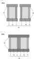
FIG. 1 is a diagram illustrating a dual-stage optical isolator according to an embodiment; -
FIG. 2 is a diagram illustrating a dual-stage optical isolator according to another embodiment; -
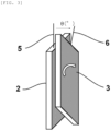
FIG. 3 is a diagram illustrating a relative angle θ between the transmitted light polarization axes of second and third polarizers; -
FIG. 4 is a graph illustrating a relationship between the relative angle θ between the transmitted light polarization axes of the second and third polarizers and backward insertion loss of the optical isolator; -
FIG. 5 is a graph (enlarged) illustrating a relationship between the relative angle θ between the transmitted light polarization axes of the second and third polarizers and backward insertion loss of the optical isolator; -
FIG. 6 is a graph illustrating an evaluation result of wavelength dependence of backward insertion loss in a dual-stage optical isolator of Example 1; -
FIG. 7 is a graph illustrating a relationship between the relative angle θ of the transmitted light polarization axes of the second and third polarizers and forward insertion loss; and -
FIG. 8 is a graph illustrating backward insertion loss of a dual-stage optical isolator and wavelength dependence of extinction performance of the second and third polarizers according to an embodiment. - Hereinafter, the present invention will be described in detail. However, the present invention is not limited thereto.
- As described above, there has been a need for an optical isolator having high light-blocking performance.
- The inventors of the present invention have conducted elaborate studies on the problem above and found that an optical isolator having high light-blocking performance can be provided by an optical isolator with multiple stages that includes: an optical element including at least a first polarizer, a first Faraday rotator, a second polarizer, a third polarizer, a second Faraday rotator, and a fourth polarizer in sequence in a direction in which light travels; and at least one permanent magnet configured to apply a magnetic field to the first Faraday rotator and the second Faraday rotator, in which a relative angle between a transmitted light polarization axis of the second polarizer and a transmitted light polarization axis of the third polarizer is equal to or more than 0.1 degrees. This finding has led to completion of the present invention.
- Hereinafter, a description will be given with reference to the drawings.
- First of all, an optical isolator with a multi-stage construction will be described.
FIG. 1 illustrates a dual-stage optical isolator 100A according to an embodiment as an example. As illustrated inFIG. 1 , the dual-stage optical isolator 100A includes four polarizers and two Faraday rotators. The dual-stage optical isolator 100A includes anoptical element 10 having afirst polarizer 1, afirst Faraday rotator 13, asecond polarizer 2, athird polarizer 3, asecond Faraday rotator 14, and afourth polarizer 4 in sequence in a forward direction (direction in which light travels), apermanent magnet 11 to apply a magnetic field to thefirst Faraday rotator 13, and apermanent magnet 12 to apply a magnetic field to thesecond Faraday rotator 14.FIG. 1 illustrates an example in which a section including a first stage of the optical element 10 (first polarizer 1,first Faraday rotator 13, second polarizer 2) and thepermanent magnet 11 is separate from a section including a second stage of the optical element 10 (third polarizer 3,second Faraday rotator 14, fourth polarizer 4) and thepermanent magnet 12. - Preferably, multiple stages are integrated to make a multi-stage optical isolator. For example, the first stage and the second stage illustrated in
FIG. 1 may be integrated to make an integrated, dual-stageoptical isolator 100B as illustrated inFIG. 2 . In this case, the optical isolator may include a singlepermanent magnet 15 as a permanent magnet that applies a magnetic field to thefirst Faraday rotator 13 and thesecond Faraday rotator 14. Such an optical isolator can be reduced in size because the gap between the second polarizer and the third polarizer is eliminated. - Known polarizers, Faraday rotators and permanent magnets can be employed as appropriate for the first polarizer, the first Faraday rotator, the second polarizer, the third polarizer, the second Faraday rotators, the fourth polarizer, and the permanent magnet. For example, (TbEuBi)3(FeGa)5O12 or (GdBi)3(FeGa)5O12 can be used for the Faraday rotators. Although the dual-stage optical isolator has been described above as an example, a multi-stage optical isolator with more than two stages can be employed.
- In the multi-stage optical isolator according to the present invention, the relative angle θ between the transmitted light polarization axis of the
second polarizer 2 and the transmitted light polarization axis of thethird polarizer 3 is equal to or more than 0.1 degrees. For example, as illustrated inFIG. 3 , the relative angle θ between the transmittedlight polarization axis 5 of thesecond polarizer 2 and the transmittedlight polarization axis 6 of thethird polarizer 3 can be adjusted by rotating thesecond polarizer 2 and thethird polarizer 3 relative to each other while keeping them parallel. In this way, when the relative angle θ between the transmitted light polarization axes of the second and third polarizers located at a central portion of theoptical element 10 and adjacent to each other is shifted from 0.0 degrees (°) and the relative angle θ between the transmitted light polarization axes is set to equal to or more than 0.1 degrees (°), a high backward insertion loss can be obtained without being limited to the extinction performance value of the second and third polarizers. - The second polarizer and the third polarizer are preferably flat-plate polarizers. In the optical isolator with such second polarizer and third polarizer, the relative angle θ between the transmitted light polarization axes can be set more stably.
-
FIG. 8 illustrates an example of backward insertion loss of the dual-stage optical isolator and wavelength dependence of extinction performance of the second and third polarizers. Assuming that the extinction performance of the polarizer used is infinitely large, the backward insertion loss of the optical isolator calculated from the wavelength dependence of the Faraday rotation angle of the Faraday rotator used is as indicated by a dash-dot line inFIG. 8 . In actual, the extinction performance of polarizers is finite, and the extinction performance of the second and third polarizers has the characteristic as indicated by the dotted line relative to the optical wavelength. The solid line inFIG. 8 indicates the measured value of backward insertion loss of the dual-stage optical isolator, where the relative angle θ between the transmitted light polarization axes of the second and third polarizers is 0.0 degrees (°). As indicated by the solid line inFIG. 8 , the value of backward insertion loss obtained by inserting two (dual-stage) isolators is adjacent to the extinction performance of the second and third polarizers, suggesting that the backward insertion loss is dependent on and limited by the extinction performance of the polarizer located in the middle. - The inventors of the present invention have found that as the relative angle θ between the transmitted light polarization axes of the second and third polarizers is gradually increased from 0.0 degrees (°), the backward insertion loss of the optical isolator increases away from the extinction performance of the polarizers and exhibits a greater value.
FIG. 4 andFIG. 5 illustrate a relationship between the relative angle θ between the transmitted light polarization axes of the second and third polarizers and the backward insertion loss of the optical isolator. For comparison, the extinction performance of the polarizer (dotted line) is also illustrated.FIG. 4 illustrates the relative angle θ in the range of 0 to 14 degrees (°), andFIG. 5 is an enlarged illustration of the relative angle θ from 0 to 2 degrees (°). As illustrated inFIGs. 4 and5 , as the relative angle θ between the transmitted light polarization axes of the second and third polarizers is gradually increased from 0.0 degrees (°), the backward insertion loss of the optical isolator increases away from the extinction performance of the polarizers and exhibits a greater value. Presumably, the relative angle between the transmitted light polarization axes acts to allow each of the polarizers to have an independent function. - Presumably, when the relative angle θ between the transmitted light polarization axes of the second and third polarizers is 0.0 degrees (°), the second and third polarizers function integrally and consequently exhibit the same behavior as a 1.5-stage optical isolator (three polarizers, two Faraday rotators), and there is a strong dependence on the performance of the polarizers.
- On the other hand, as illustrated in
FIG. 7 , it was confirmed that as the relative angle θ between transmitted light polarization axes of the second and third polarizers is increased, the forward insertion loss of the optical isolator gradually increases from 0.18 dB at which the relative angle θ between the transmitted light polarization axes is 0.0 degrees (°). In the optical isolator according to the present invention, the upper limit of the relative angle θ between the transmitted light polarization axes of the second and third polarizers is not limited, but the upper limit of the relative angle θ between the transmitted light polarization axes can be, for example, equal to or less than 10.0 degrees (°), preferably equal to or less than 5.0 degrees (°), more preferably equal to or less than 1.0 degrees (°), considering that the forward insertion loss is required to have a smaller value. - Hereinafter, the present invention will be specifically described with Examples. However, the present invention is not limited thereto.
- A dual-stage optical isolator as illustrated in
FIG. 1 was produced. A flat-plate glass polarizer (Polarcor from Corning Incorporated) in which Ag particles were dispersed and oriented was used as a polarizer. (TbEuBi)3(FeGa)5O12 was used for a Faraday rotator. - As first and second polarizers, a 1550 nm AR coat for air was applied to the surfaces of polarizing glasses (11 mm square, 0.2 mm thick, extinction performance 52dB) corresponding to a light input surface and a light output surface. An anti-epoxy coat was applied to both surfaces of a 45.0 degree Faraday rotator for 1550 nm (11 mm square, 0.54 mm thick), and the Faraday rotator was laminated with the AR coat-free surfaces of the polarizing glasses via epoxy adhesive and securely bonded so that the relative angle between the transmitted light polarization axes of the first and second polarizers was 45.0 degrees. Subsequently, the resulting laminate was cut and processed into a 2 mm square, which was inserted into a permanent magnet (outer diameter 5.0 mm × inner diameter 2.9 mm × length 1.2 mm) and securely bonded. This was the first stage of the dual-stage optical isolator. The third polarizer, the fourth polarizer, the second Faraday rotator, and the permanent magnet in the second stage were also prepared with the same materials and through the same procedure as the first stage.
- The relative angle θ between the transmitted light polarization axes of the second and third polarizers was set to 0.0 degrees (°). In this case, as indicated by the solid line in
FIG. 8 , the value of backward insertion loss obtained by inserting two isolators was adjacent to the extinction performance of the second and third polarizers. As previously mentioned, this suggests that the backward insertion loss is dependent on the extinction performance of the polarizer located in the middle. Presumably, the second and third polarizers functioned integrally and consequently exhibited the same behavior as a 1.5-stage optical isolator (three polarizers, two Faraday rotators), and there was a strong dependence on the performance of the polarizers. - The relative angle θ between the transmitted light polarization axes of the second and third polarizers was fixed to 0.3 degrees (°), and the wavelength dependence of backward insertion loss was evaluated. The result is shown in
FIG. 6 . InFIG. 6 , the solid line indicates the measured value of wavelength dependence of backward insertion loss in Example 1. The dash-dot line and the dotted line are the same as those inFIG. 4 . Unlike the solid line inFIG. 8 , the measured value of wavelength dependence of backward insertion loss in Example 1 is high in the overall evaluation wavelength range and exhibits behavior closer to the calculated value from wavelength dependence of Faraday rotation angle of the Faraday rotator as indicated by the dash-dot line. Also in this respect, higher backward insertion loss can be achieved compared with the polarizer extinction performance dependence. - An integrated dual-stage optical isolator as illustrated in
FIG. 2 was produced. Polarizingglasses 15 mm square and 0.12 mm thick (extinction performance 52dB) were used as polarizers, and a 1550 nm AR coat for air was applied to the surfaces of the first and fourth polarizing glasses. An anti-epoxy coat was applied to both surfaces of each of 45.0 degree Faraday rotators for 1550 nm (0.41 mm thick) used as 15 mm square first and second Faraday rotators. The Faraday rotators were laminated with the AR coat-free surfaces of the polarizing glasses via epoxy adhesive and securely bonded so that the relative angles between the first and second polarizers and between the third and fourth polarizers were each 45.0 degrees. Subsequently, the laminates were securely bonded so that the relative angle θ between the transmitted light polarization axes of the second and third polarizers was 0.5 degrees. An integrated dual-stage optical isolator plate was thus produced. Subsequently, the resulting plate was cut and processed into a 0.8 mm square, which was inserted into a permanent magnet (outer diameter 3.0 × inner diameter 1.2 mm × length 1.6 mm) and securely bonded. The produced optical isolator had high light-blocking performance, such as forward insertion loss of 0.20 dB and backward insertion loss of 73dB, for light with a wavelength of 1550 nm. - As described above, according to the examples of the present invention, an optical isolator having high light-blocking performance was obtained.
- The specification includes the following embodiments.
- [1]: An optical isolator with multiple stages, comprising: an optical element comprising at least a first polarizer, a first Faraday rotator, a second polarizer, a third polarizer, a second Faraday rotator, and a fourth polarizer in sequence in a direction in which light travels; and at least one permanent magnet configured to apply a magnetic field to the first Faraday rotator and the second Faraday rotator,
wherein a relative angle between a transmitted light polarization axis of the second polarizer and a transmitted light polarization axis of the third polarizer is equal to or more than 0.1 degrees. - [2]: The optical isolator of the above [1], wherein the first polarizer, the first Faraday rotator, and the second polarizer are integrated, and the third polarizer, the second Faraday rotator, and the fourth polarizer are integrated.
- [3]: The optical isolator of the above [1] or the above [2], wherein the second polarizer and the third polarizer are flat-plate polarizers.
- It should be noted that the present invention is not limited to the above-described embodiments. The embodiments are just examples, and any examples that substantially have the same feature and demonstrate the same functions and effects as those in the technical concept disclosed in claims of the present invention are included in the technical scope of the present invention.
Claims (3)
- An optical isolator with multiple stages, comprising: an optical element comprising at least a first polarizer, a first Faraday rotator, a second polarizer, a third polarizer, a second Faraday rotator, and a fourth polarizer in sequence in a direction in which light travels; and at least one permanent magnet configured to apply a magnetic field to the first Faraday rotator and the second Faraday rotator,
wherein a relative angle between a transmitted light polarization axis of the second polarizer and a transmitted light polarization axis of the third polarizer is equal to or more than 0.1 degrees. - The optical isolator according to claim 1, wherein the first polarizer, the first Faraday rotator, and the second polarizer are integrated, and the third polarizer, the second Faraday rotator, and the fourth polarizer are integrated.
- The optical isolator according to claim 1 or 2, wherein the second polarizer and the third polarizer are flat-plate polarizers.
Applications Claiming Priority (2)
| Application Number | Priority Date | Filing Date | Title |
|---|---|---|---|
| JP2022077129A JP7634500B2 (en) | 2022-05-09 | 2022-05-09 | Optical Isolator |
| PCT/JP2023/016604 WO2023218984A1 (en) | 2022-05-09 | 2023-04-27 | Optical isolator |
Publications (2)
| Publication Number | Publication Date |
|---|---|
| EP4524644A1 true EP4524644A1 (en) | 2025-03-19 |
| EP4524644A4 EP4524644A4 (en) | 2026-04-29 |
Family
ID=88730431
Family Applications (1)
| Application Number | Title | Priority Date | Filing Date |
|---|---|---|---|
| EP23803463.1A Pending EP4524644A4 (en) | 2022-05-09 | 2023-04-27 | OPTICAL ISOLATOR |
Country Status (6)
| Country | Link |
|---|---|
| US (1) | US20250341739A1 (en) |
| EP (1) | EP4524644A4 (en) |
| JP (1) | JP7634500B2 (en) |
| CN (1) | CN119072647A (en) |
| CA (1) | CA3257153A1 (en) |
| WO (1) | WO2023218984A1 (en) |
Family Cites Families (6)
| Publication number | Priority date | Publication date | Assignee | Title |
|---|---|---|---|---|
| JPH0283522A (en) * | 1988-09-20 | 1990-03-23 | Yokogawa Electric Corp | Optical isolator |
| JPH02272419A (en) | 1989-04-13 | 1990-11-07 | Hitachi Metals Ltd | Small-sized two-stage optical isolator |
| JP2565423B2 (en) * | 1990-11-19 | 1996-12-18 | 並木精密宝石株式会社 | Optical isolator |
| US5808793A (en) * | 1996-01-17 | 1998-09-15 | Hewlett-Packard Company | Low-cost compact optical isolators |
| JP2000171631A (en) * | 1998-12-01 | 2000-06-23 | Kyocera Corp | Polarizer and optical isolator using the same |
| JP2005134492A (en) * | 2003-10-28 | 2005-05-26 | Kyocera Corp | Optical isolator and manufacturing method thereof |
-
2022
- 2022-05-09 JP JP2022077129A patent/JP7634500B2/en active Active
-
2023
- 2023-04-27 CA CA3257153A patent/CA3257153A1/en active Pending
- 2023-04-27 CN CN202380038533.6A patent/CN119072647A/en active Pending
- 2023-04-27 EP EP23803463.1A patent/EP4524644A4/en active Pending
- 2023-04-27 WO PCT/JP2023/016604 patent/WO2023218984A1/en not_active Ceased
- 2023-04-27 US US18/862,200 patent/US20250341739A1/en active Pending
Also Published As
| Publication number | Publication date |
|---|---|
| CA3257153A1 (en) | 2025-04-14 |
| US20250341739A1 (en) | 2025-11-06 |
| CN119072647A (en) | 2024-12-03 |
| EP4524644A4 (en) | 2026-04-29 |
| WO2023218984A1 (en) | 2023-11-16 |
| JP2023166222A (en) | 2023-11-21 |
| JP7634500B2 (en) | 2025-02-21 |
Similar Documents
| Publication | Publication Date | Title |
|---|---|---|
| JP5205602B2 (en) | Inline optical isolator | |
| US5880875A (en) | Light amplifier having a multi-stage optical isolator | |
| US7961391B2 (en) | Free space isolator optical element fixture | |
| US20250341739A1 (en) | Optical isolator | |
| JP6297988B2 (en) | Optical isolator module and optical semiconductor module | |
| US6049425A (en) | Multiple-stage optical isolator | |
| JP4696830B2 (en) | Polarization-independent optical isolator | |
| US11409144B2 (en) | Optical isolator | |
| US6711185B2 (en) | Polarization dependent out-coupling | |
| JP6226428B2 (en) | A method of manufacturing a polarization maintaining fiber with an optical isolator. | |
| JP3973975B2 (en) | Optical isolator | |
| EP4644972A1 (en) | Optical isolator | |
| GB2143337A (en) | Optical isolator | |
| US20030030905A1 (en) | Polarized wave coupling optical isolator | |
| JP2006208710A (en) | Optical isolator element, manufacturing method thereof, and fiber with optical isolator | |
| JP6557119B2 (en) | Optical isolator and method for manufacturing optical isolator | |
| JP2002156530A (en) | Optical fiber pigtail with optical isolator | |
| JPH10142558A (en) | Optical isolator and method of manufacturing the same | |
| JP2024095329A (en) | Optical isolator and method for manufacturing the same | |
| JPS61132925A (en) | Semiconductor laser module with optical isolator | |
| JPH02272419A (en) | Small-sized two-stage optical isolator | |
| JP2021064010A (en) | Optical isolator | |
| JPH02221912A (en) | Optical isolator | |
| JPH01248112A (en) | Light emitting element module | |
| JPH0255313A (en) | Optical isolator |
Legal Events
| Date | Code | Title | Description |
|---|---|---|---|
| STAA | Information on the status of an ep patent application or granted ep patent |
Free format text: STATUS: THE INTERNATIONAL PUBLICATION HAS BEEN MADE |
|
| PUAI | Public reference made under article 153(3) epc to a published international application that has entered the european phase |
Free format text: ORIGINAL CODE: 0009012 |
|
| STAA | Information on the status of an ep patent application or granted ep patent |
Free format text: STATUS: REQUEST FOR EXAMINATION WAS MADE |
|
| 17P | Request for examination filed |
Effective date: 20241105 |
|
| AK | Designated contracting states |
Kind code of ref document: A1 Designated state(s): AL AT BE BG CH CY CZ DE DK EE ES FI FR GB GR HR HU IE IS IT LI LT LU LV MC ME MK MT NL NO PL PT RO RS SE SI SK SM TR |
|
| DAV | Request for validation of the european patent (deleted) | ||
| DAX | Request for extension of the european patent (deleted) | ||
| A4 | Supplementary search report drawn up and despatched |
Effective date: 20260327 |
|
| RIC1 | Information provided on ipc code assigned before grant |
Ipc: G02B 27/28 20060101AFI20260323BHEP |