EP4524455A2 - Flüssiggasspeichertank und schiff damit - Google Patents
Flüssiggasspeichertank und schiff damit Download PDFInfo
- Publication number
- EP4524455A2 EP4524455A2 EP25150020.3A EP25150020A EP4524455A2 EP 4524455 A2 EP4524455 A2 EP 4524455A2 EP 25150020 A EP25150020 A EP 25150020A EP 4524455 A2 EP4524455 A2 EP 4524455A2
- Authority
- EP
- European Patent Office
- Prior art keywords
- corner
- barrier
- primary
- insulation wall
- liquefied gas
- Prior art date
- Legal status (The legal status is an assumption and is not a legal conclusion. Google has not performed a legal analysis and makes no representation as to the accuracy of the status listed.)
- Pending
Links
Images















Classifications
-
- B—PERFORMING OPERATIONS; TRANSPORTING
- B63—SHIPS OR OTHER WATERBORNE VESSELS; RELATED EQUIPMENT
- B63B—SHIPS OR OTHER WATERBORNE VESSELS; EQUIPMENT FOR SHIPPING
- B63B25/00—Load-accommodating arrangements, e.g. stowing, trimming; Vessels characterised thereby
- B63B25/02—Load-accommodating arrangements, e.g. stowing, trimming; Vessels characterised thereby for bulk goods
- B63B25/08—Load-accommodating arrangements, e.g. stowing, trimming; Vessels characterised thereby for bulk goods fluid
- B63B25/12—Load-accommodating arrangements, e.g. stowing, trimming; Vessels characterised thereby for bulk goods fluid closed
- B63B25/16—Load-accommodating arrangements, e.g. stowing, trimming; Vessels characterised thereby for bulk goods fluid closed heat-insulated
-
- B—PERFORMING OPERATIONS; TRANSPORTING
- B63—SHIPS OR OTHER WATERBORNE VESSELS; RELATED EQUIPMENT
- B63B—SHIPS OR OTHER WATERBORNE VESSELS; EQUIPMENT FOR SHIPPING
- B63B73/00—Building or assembling vessels or marine structures, e.g. hulls or offshore platforms
- B63B73/20—Building or assembling prefabricated vessel modules or parts other than hull blocks, e.g. engine rooms, rudders, propellers, superstructures, berths, holds or tanks
-
- F—MECHANICAL ENGINEERING; LIGHTING; HEATING; WEAPONS; BLASTING
- F17—STORING OR DISTRIBUTING GASES OR LIQUIDS
- F17C—VESSELS FOR CONTAINING OR STORING COMPRESSED, LIQUEFIED OR SOLIDIFIED GASES; FIXED-CAPACITY GAS-HOLDERS; FILLING VESSELS WITH, OR DISCHARGING FROM VESSELS, COMPRESSED, LIQUEFIED, OR SOLIDIFIED GASES
- F17C3/00—Vessels not under pressure
- F17C3/02—Vessels not under pressure with provision for thermal insulation
- F17C3/025—Bulk storage in barges or on ships
- F17C3/027—Wallpanels for so-called membrane tanks
-
- B—PERFORMING OPERATIONS; TRANSPORTING
- B63—SHIPS OR OTHER WATERBORNE VESSELS; RELATED EQUIPMENT
- B63B—SHIPS OR OTHER WATERBORNE VESSELS; EQUIPMENT FOR SHIPPING
- B63B25/00—Load-accommodating arrangements, e.g. stowing, trimming; Vessels characterised thereby
- B63B25/02—Load-accommodating arrangements, e.g. stowing, trimming; Vessels characterised thereby for bulk goods
- B63B25/08—Load-accommodating arrangements, e.g. stowing, trimming; Vessels characterised thereby for bulk goods fluid
- B63B25/12—Load-accommodating arrangements, e.g. stowing, trimming; Vessels characterised thereby for bulk goods fluid closed
- B63B25/14—Load-accommodating arrangements, e.g. stowing, trimming; Vessels characterised thereby for bulk goods fluid closed pressurised
-
- F—MECHANICAL ENGINEERING; LIGHTING; HEATING; WEAPONS; BLASTING
- F17—STORING OR DISTRIBUTING GASES OR LIQUIDS
- F17C—VESSELS FOR CONTAINING OR STORING COMPRESSED, LIQUEFIED OR SOLIDIFIED GASES; FIXED-CAPACITY GAS-HOLDERS; FILLING VESSELS WITH, OR DISCHARGING FROM VESSELS, COMPRESSED, LIQUEFIED, OR SOLIDIFIED GASES
- F17C2201/00—Vessel construction, in particular geometry, arrangement or size
- F17C2201/01—Shape
- F17C2201/0147—Shape complex
- F17C2201/0157—Polygonal
-
- F—MECHANICAL ENGINEERING; LIGHTING; HEATING; WEAPONS; BLASTING
- F17—STORING OR DISTRIBUTING GASES OR LIQUIDS
- F17C—VESSELS FOR CONTAINING OR STORING COMPRESSED, LIQUEFIED OR SOLIDIFIED GASES; FIXED-CAPACITY GAS-HOLDERS; FILLING VESSELS WITH, OR DISCHARGING FROM VESSELS, COMPRESSED, LIQUEFIED, OR SOLIDIFIED GASES
- F17C2201/00—Vessel construction, in particular geometry, arrangement or size
- F17C2201/05—Size
- F17C2201/052—Size large (>1000 m3)
-
- F—MECHANICAL ENGINEERING; LIGHTING; HEATING; WEAPONS; BLASTING
- F17—STORING OR DISTRIBUTING GASES OR LIQUIDS
- F17C—VESSELS FOR CONTAINING OR STORING COMPRESSED, LIQUEFIED OR SOLIDIFIED GASES; FIXED-CAPACITY GAS-HOLDERS; FILLING VESSELS WITH, OR DISCHARGING FROM VESSELS, COMPRESSED, LIQUEFIED, OR SOLIDIFIED GASES
- F17C2203/00—Vessel construction, in particular walls or details thereof
- F17C2203/03—Thermal insulations
- F17C2203/0304—Thermal insulations by solid means
- F17C2203/0358—Thermal insulations by solid means in form of panels
-
- F—MECHANICAL ENGINEERING; LIGHTING; HEATING; WEAPONS; BLASTING
- F17—STORING OR DISTRIBUTING GASES OR LIQUIDS
- F17C—VESSELS FOR CONTAINING OR STORING COMPRESSED, LIQUEFIED OR SOLIDIFIED GASES; FIXED-CAPACITY GAS-HOLDERS; FILLING VESSELS WITH, OR DISCHARGING FROM VESSELS, COMPRESSED, LIQUEFIED, OR SOLIDIFIED GASES
- F17C2203/00—Vessel construction, in particular walls or details thereof
- F17C2203/06—Materials for walls or layers thereof; Properties or structures of walls or their materials
- F17C2203/0602—Wall structures; Special features thereof
- F17C2203/0612—Wall structures
- F17C2203/0626—Multiple walls
- F17C2203/0631—Three or more walls
-
- F—MECHANICAL ENGINEERING; LIGHTING; HEATING; WEAPONS; BLASTING
- F17—STORING OR DISTRIBUTING GASES OR LIQUIDS
- F17C—VESSELS FOR CONTAINING OR STORING COMPRESSED, LIQUEFIED OR SOLIDIFIED GASES; FIXED-CAPACITY GAS-HOLDERS; FILLING VESSELS WITH, OR DISCHARGING FROM VESSELS, COMPRESSED, LIQUEFIED, OR SOLIDIFIED GASES
- F17C2203/00—Vessel construction, in particular walls or details thereof
- F17C2203/06—Materials for walls or layers thereof; Properties or structures of walls or their materials
- F17C2203/0634—Materials for walls or layers thereof
-
- F—MECHANICAL ENGINEERING; LIGHTING; HEATING; WEAPONS; BLASTING
- F17—STORING OR DISTRIBUTING GASES OR LIQUIDS
- F17C—VESSELS FOR CONTAINING OR STORING COMPRESSED, LIQUEFIED OR SOLIDIFIED GASES; FIXED-CAPACITY GAS-HOLDERS; FILLING VESSELS WITH, OR DISCHARGING FROM VESSELS, COMPRESSED, LIQUEFIED, OR SOLIDIFIED GASES
- F17C2221/00—Handled fluid, in particular type of fluid
- F17C2221/01—Pure fluids
-
- F—MECHANICAL ENGINEERING; LIGHTING; HEATING; WEAPONS; BLASTING
- F17—STORING OR DISTRIBUTING GASES OR LIQUIDS
- F17C—VESSELS FOR CONTAINING OR STORING COMPRESSED, LIQUEFIED OR SOLIDIFIED GASES; FIXED-CAPACITY GAS-HOLDERS; FILLING VESSELS WITH, OR DISCHARGING FROM VESSELS, COMPRESSED, LIQUEFIED, OR SOLIDIFIED GASES
- F17C2221/00—Handled fluid, in particular type of fluid
- F17C2221/03—Mixtures
- F17C2221/032—Hydrocarbons
- F17C2221/033—Methane, e.g. natural gas, CNG, LNG, GNL, GNC, PLNG
-
- F—MECHANICAL ENGINEERING; LIGHTING; HEATING; WEAPONS; BLASTING
- F17—STORING OR DISTRIBUTING GASES OR LIQUIDS
- F17C—VESSELS FOR CONTAINING OR STORING COMPRESSED, LIQUEFIED OR SOLIDIFIED GASES; FIXED-CAPACITY GAS-HOLDERS; FILLING VESSELS WITH, OR DISCHARGING FROM VESSELS, COMPRESSED, LIQUEFIED, OR SOLIDIFIED GASES
- F17C2221/00—Handled fluid, in particular type of fluid
- F17C2221/03—Mixtures
- F17C2221/032—Hydrocarbons
- F17C2221/035—Propane butane, e.g. LPG, GPL
-
- F—MECHANICAL ENGINEERING; LIGHTING; HEATING; WEAPONS; BLASTING
- F17—STORING OR DISTRIBUTING GASES OR LIQUIDS
- F17C—VESSELS FOR CONTAINING OR STORING COMPRESSED, LIQUEFIED OR SOLIDIFIED GASES; FIXED-CAPACITY GAS-HOLDERS; FILLING VESSELS WITH, OR DISCHARGING FROM VESSELS, COMPRESSED, LIQUEFIED, OR SOLIDIFIED GASES
- F17C2223/00—Handled fluid before transfer, i.e. state of fluid when stored in the vessel or before transfer from the vessel
- F17C2223/01—Handled fluid before transfer, i.e. state of fluid when stored in the vessel or before transfer from the vessel characterised by the phase
- F17C2223/0146—Two-phase
- F17C2223/0153—Liquefied gas, e.g. LPG, GPL
- F17C2223/0161—Liquefied gas, e.g. LPG, GPL cryogenic, e.g. LNG, GNL, PLNG
-
- F—MECHANICAL ENGINEERING; LIGHTING; HEATING; WEAPONS; BLASTING
- F17—STORING OR DISTRIBUTING GASES OR LIQUIDS
- F17C—VESSELS FOR CONTAINING OR STORING COMPRESSED, LIQUEFIED OR SOLIDIFIED GASES; FIXED-CAPACITY GAS-HOLDERS; FILLING VESSELS WITH, OR DISCHARGING FROM VESSELS, COMPRESSED, LIQUEFIED, OR SOLIDIFIED GASES
- F17C2223/00—Handled fluid before transfer, i.e. state of fluid when stored in the vessel or before transfer from the vessel
- F17C2223/03—Handled fluid before transfer, i.e. state of fluid when stored in the vessel or before transfer from the vessel characterised by the pressure level
- F17C2223/033—Small pressure, e.g. for liquefied gas
-
- F—MECHANICAL ENGINEERING; LIGHTING; HEATING; WEAPONS; BLASTING
- F17—STORING OR DISTRIBUTING GASES OR LIQUIDS
- F17C—VESSELS FOR CONTAINING OR STORING COMPRESSED, LIQUEFIED OR SOLIDIFIED GASES; FIXED-CAPACITY GAS-HOLDERS; FILLING VESSELS WITH, OR DISCHARGING FROM VESSELS, COMPRESSED, LIQUEFIED, OR SOLIDIFIED GASES
- F17C2270/00—Applications
- F17C2270/01—Applications for fluid transport or storage
- F17C2270/0102—Applications for fluid transport or storage on or in the water
- F17C2270/0105—Ships
- F17C2270/0107—Wall panels
Definitions
- the present invention relates to a liquefied gas storage tank and a vessel including the same.
- liquefied gases such as liquefied natural gas (LNG) and liquefied petroleum gas (LPG) have been widely used to replace gasoline or diesel according to technological development.
- LNG liquefied natural gas
- LPG liquefied petroleum gas
- a storage tank for storing LNG in a cryogenic liquid state is installed in vessels, such as LNG cargo vessels, LNG regasification vessels (RVs), LNG floating, production, storage, and offloading (FPSO) vessels, and LNG floating storage and regasification units (FSRUs) for transporting or storing the liquefied gases such as LNG at sea.
- vessels such as LNG cargo vessels, LNG regasification vessels (RVs), LNG floating, production, storage, and offloading (FPSO) vessels, and LNG floating storage and regasification units (FSRUs) for transporting or storing the liquefied gases such as LNG at sea.
- RVs LNG regasification vessels
- FPSO production, storage, and offloading
- FSRUs LNG floating storage and regasification units
- the present invention has been made in efforts to solve the above problem of the related art and is directed to providing a liquefied gas storage tank and a vessel including the same, in which a structure of a corner block is improved, thereby reducing a low-temperature load, sloshing load, and stress load of a secondary corner barrier.
- a liquefied gas storage tank includes a corner block that is disposed on a corner portion in which a first surface and a second surface at different angles meet each other and forms a storage space accommodating liquefied gas
- the corner block may include a lower block provided inside the first and second surfaces and formed of a single board, an upper block bonded and connected to a secondary barrier of the lower block, and an upper connecting block bonded and connected to the secondary barrier on an upper surface of the lower block disposed adjacent thereto each other to connect the lower blocks
- the upper block may include a first inner fixing unit and a second inner fixing unit respectively provided inside the first surface and the second surface, bonded and connected to the secondary barrier, and each having a structure in which a primary inner plywood, a primary corner insulating material, and a primary outer plywood are stacked, and an inner bent portion installed at a corner spatial portion between the first inner fixing unit and the second inner fixing unit, and both side surfaces of the inner bent portion that are perpendicular to the secondary barrier may each have
- the inner bent portion may have first protrusions provided on both side surfaces, and the first protrusion may extend outward from the corner spatial portion as much as a predetermined length from the inner bent portion inserted into the corner spatial portion formed by the first and second inner fixing units, have a cross-sectional shape which is similar to a shape of the inner bent portion and in which a curved portion, which is in contact with the secondary barrier, collinearly extends from a curved portion of the inner bent portion, and form first steps between both side surfaces that are perpendicular to the secondary barrier and both side surfaces of the inner bent portion.
- the upper connecting block may include a first corner connecting fixing unit and a second corner connecting fixing unit respectively provided inside the first surface and the second surface, bonded and connected to the secondary barrier, and each having a structure in which a first corner connecting plywood, a corner connecting insulating material, and a second corner connecting plywood are stacked, and a corner connecting bent portion installed in a corner spatial portion between the first corner connecting fixing unit and the second corner connecting fixing unit, wherein both side surfaces of the inner bent portion that are perpendicular to the secondary barrier may each have a height reduced from a total height of each of the first and second corner connecting fixing units, second protrusions may be provided on both side surfaces, and the second protrusion may extend outward from the corner spatial portion as much as a predetermined length from the corner connecting bent portion inserted into the corner spatial portion formed by the first and second corner connecting fixing units, have a cross-sectional shape which is similar to a shape of the corner connecting bent portion and in which a curved portion, which is in contact with the secondary barrier, collinearly extends
- the first and second protrusions may be in contact with each other when the upper connecting block is installed between the adj acent upper blocks, and step spaces are formed between the first and second inner fixing units and the first and second corner connecting fixing units, a stuffing piece may be inserted and installed in the step space, and the stuffing piece may have a positive (+) tolerance to seal the step space and may be formed in a shape corresponding to a shape of the step space.
- the first and second inner fixing units may be symmetrically provided with respect to a direction in which the corner portion is equally divided and have first side surfaces that are in close contact with both side surfaces of the inner bent portion and perpendicular to the secondary barrier and second side surfaces that extend from the first side surfaces toward the storage space in the same direction as the direction of the division
- the upper block may further include a corner inner packing material inserted and installed in spaces formed between the first side surfaces in close contact with both side surfaces of the inner bent portion and between the second side surfaces facing each other, and the corner inner packing material may be formed to have a positive (+) tolerance to seal the space in a state of being inserted into the space between the second side surfaces.
- a liquefied gas storage tank includes a corner block that is disposed on a corner portion in which a first surface and a second surface at different angles meet each other and forms a storage space accommodating liquefied gas
- the corner block may include a lower block provided inside the first surface and the second surface and formed of a single board, an integrated upper block bonded and connected to a secondary barrier of the lower block and formed of a single board, an upper connecting block bonded and connected to the secondary barrier exposed between the integrated upper blocks disposed adjacent to each other, and a barrier fixing member installed on an upper surface of the integrated upper block and configured to fix a primary barrier
- the integrated upper block may include one primary outer plywood provided inside each of the first surface and the second surface and bonded and connected to the secondary barrier, one primary corner insulating material stacked on the primary outer plywood, and one primary inner plywood stacked on the primary corner insulating material
- the barrier fixing member may be formed of a plurality of unit barrier fixing members side by side installed adjacent to each other on the one primary
- the integrated upper block may include a plurality of upper slits formed in an upper portion thereof at a predetermined depth, and the plurality of upper slits may pass through the primary inner plywood and may be formed to at least a portion of the primary corner insulating material in order to cope with contraction or expansion stress of the primary corner insulating material, and may be formed at corresponding positions between the plurality of unit barrier fixing members so that the plurality of unit barrier fixing members interlock with contraction or expansion of the primary corner insulating material.
- the integrated upper block may include a plurality of upper slits formed in an upper portion thereof at a predetermined depth, and a plurality of lower slits formed in a lower portion thereof at a predetermined depth, wherein the plurality of upper slits and the plurality of lower slits may be formed at positions that are misaligned.
- the primary outer plywood may have a plurality of first grooves formed in a lower surface bonded and connected to the secondary barrier, the plurality of first grooves may be formed in a direction perpendicular to a corner side of the storage tank to check a squeeze-out of an adhesive into a non-adhesive region when the primary outer plywood is bonded on the secondary barrier with the adhesive, the non-adhesive region may be provided as a plurality of non-adhesive regions set at intermediate portions in addition to both side edge portions of the primary outer plywood, and each of the plurality of non-adhesive regions may be set at a predetermined distance and width in the direction perpendicular to the corner side of the storage tank and set at a corresponding position between the plurality of unit barrier fixing members.
- the plurality of first grooves may be formed along both side boundary portions of the plurality of non-adhesive regions and disposed to be misaligned with the plurality of upper slits.
- a liquefied gas storage tank includes a corner block that is disposed on a corner portion in which a first surface and a second surface at different angles meet each other and forms a storage space accommodating liquefied gas
- the corner block may include a lower block provided inside the first and second surfaces and formed of a single board, an upper block bonded and connected to a secondary barrier of the lower block, and an upper connecting block bonded and connected to the secondary barrier on an upper surface of the lower block disposed adjacent thereto to connect the lower blocks
- the upper connecting block may include a first corner connecting fixing unit and a second corner connecting fixing unit respectively provided inside the first surface and the second surface, bonded and connected to the secondary barrier, and each having a structure in which a first corner connecting plywood, a corner connecting insulating material, and a second corner connecting plywood are stacked, and a corner connecting bent portion installed in a corner spatial portion between the first corner connecting fixing unit and the second corner connecting fixing unit, and both side surfaces of the corner connecting bent portion that are perpen
- the corner connecting bent portion may have second protrusions provided on both side surfaces, and the second protrusion may extend outward from the corner spatial portion as much as a predetermined length from the corner connecting bent portion inserted into the corner spatial portion formed by the first and second corner connecting fixing units, have a cross-sectional shape which is similar to a shape of the corner connecting bent portion and in which a curved portion, which is in contact with the secondary barrier, collinearly extends from a curved portion of the corner connecting bent portion, and extend to form second steps between both side surfaces that are perpendicular to the secondary barrier and both side surfaces of the corner connecting bent portion.
- the first and second corner connecting fixing units may be symmetrically provided with respect to a direction in which the corner portion is equally divided, and may have first side surfaces that are in close contact with both side surfaces of the corner connecting bent portion and perpendicular to the secondary barrier and second side surfaces that extend from the first side surfaces toward the storage space in the same direction as the direction of the division, the upper connecting block may further include a corner inner packing material inserted and installed in spaces formed between the first side surfaces in close contact with both side surfaces of the corner connecting bent portion and between the second side surfaces facing each other, and the corner inner packing material may be formed to have a positive (+) tolerance to seal the space in a state of being inserted into the space between the second side surfaces.
- the second corner connecting plywood may have a second groove formed in a lower surface bonded and connected to the secondary barrier, and the second groove may be formed in a direction horizontal to a corner side of the storage space to check a squeeze-out of an adhesive into a non-adhesive region when the second corner connecting plywood is bonded on the secondary barrier with the adhesive.
- the second groove may be formed in a portion adjacent to a rear edge of the second corner connecting plywood to check the squeeze-out of the adhesive into the corner connecting bent portion that is the non-adhesive region.
- a structure of a corner block is improved, thereby reducing a low-temperature load, sloshing load, and stress load of a secondary corner barrier.
- first and second inner fixing units for holding a barrier fixing member to which a primary corner barrier is fixed in the corner block which are made of a component in which plywood is combined with an insulating material of polyurethane foam rather than being made of only the plywood, it is possible to increase insulation performance, reduce a weight, and reduce costs compared to the conventional one made of only the plywood.
- the thickness of the secondary corner insulation wall is a thickness at which a mechanical strength can be maintained to a predetermined level
- it is possible to form a relatively thicker primary corner insulation wall (however, the thickness of the secondary corner insulation wall is a thickness at which a mechanical strength can be maintained to a predetermined level) than the conventional one, thereby reducing the low-temperature load and sloshing load of the secondary corner barrier, and it is possible to not only prevent damage to the secondary corner barrier but also reduce the low-temperature load of the secondary corner barrier, thereby preventing brittle fracture of a hull.
- the relatively thicker primary corner insulation wall than the conventional one, it is possible to increase a length of a portion in which the secondary corner barrier is not attached to the secondary corner insulation wall, thereby not only further reducing a probability of the damage to the secondary corner barrier including a corner connecting barrier due to an increase in flexibility of the secondary corner barrier but also easily absorbing the deformation of the hull and further reducing the low-temperature stress in the secondary corner barrier.
- the liquefied gas storage tank and the vessel including the same by forming the first inner fixing unit and the second inner fixing unit that are respectively provided inside a first surface and a second surface at different angles and spaced a predetermined distance from each other and providing an inner intermediate fixing unit between the first and second inner fixing units, it is possible to reduce a bent angle of the primary corner barrier by the inner intermediate fixing unit, thereby not only reducing the sloshing load in the primary corner barrier but also increasing a mechanical strength of a corner portion.
- the liquefied gas storage tank and the vessel including the same by forming steps at the corners in which the first outer fixing unit and the second outer fixing unit are respectively fixed to the first surface and the second surface at different angles and face each other and filling the steps with glass wool, it is possible to increase the flexibility of the secondary corner barrier including the corner connecting barrier formed above the glass wool, thereby further preventing the damage to the secondary corner barrier.
- the liquefied gas storage tank and the vessel including the same by forming the first outer fixing unit and the second outer fixing unit that are respectively fixed to the first surface and the second surface at different angles and spaced a predetermined distance from each other and providing an outer intermediate fixing unit between the first and second outer fixing units, it is possible to mitigate contraction or expansion stress caused by temperatures of the outer fixing units by each gap formed between the first outer fixing unit and the outer intermediate fixing unit and between the second outer fixing unit and the outer intermediate fixing unit when compared to one conventional gap, thereby preventing the damage to the secondary corner barrier fixed to the outer fixing units.
- the liquefied gas storage tank and the vessel including the same by forming chamfers at the corners in which the first outer fixing unit and the second outer fixing unit are respectively fixed to the first surface and the second surface at different angles and face each other and installing the secondary corner barrier along surfaces of the first and second outer fixing units including the chamfer portions, it is possible to increase a length of a portion in which the secondary corner barrier is bent to protrude to the outside and not attached to the secondary corner insulation wall, thereby not only further reducing the probability of the damage to the secondary corner barrier including the corner connecting barrier due to an increase in the flexibility of the secondary corner barrier but also easily absorbing the deformation of the hull and further reducing the low-temperature stress in the secondary corner barrier.
- the primary corner insulation walls which includes a primary inner plywood that forms a step with a primary corner insulating material, on the secondary corner insulation wall and forming the adjacent primary corner insulation walls disposed adjacent to each other, it is possible to not only easily handle the installation of the barrier fixing member through a stepped portion between the primary inner plywoods disposed adjacent to each other but also seat a packing material only on the stepped portion, thereby reducing the consumption of the packing material.
- the liquefied gas storage tank and the vessel including the same by forming an inner bent portion of the primary corner insulation wall formed of a first inner half bent portion bonded and connected to the first inner fixing unit and a second inner half bent portion bonded and connected to the second inner fixing unit and finishing a space between the first and second inner half bent portions with a corner inner finishing material, it is possible to block heat convection in the inner bent portions and prevent a heat convection phenomenon.
- the liquefied gas storage tank and the vessel including the same by reducing a size of the inner bent portion (or the corner connecting bent portion) of the primary corner insulation wall to about half size of the first and second inner fixing units (or the first and second corner connecting fixing units) of the primary corner insulation wall (or the corner connecting insulation wall), it is possible to reduce a space (non-adhesive region between the inner bent portion and the secondary barrier at the corner portion) in which the heat convection is generated in the inner bent portion (or the corner connecting bent portion) as a reduced area due to a change in temperature becomes smaller than the conventional inner bent portion formed at the same height as the first and second inner fixing units, thereby reducing the heat convection phenomenon.
- the size of the inner bent portion (or the corner connecting bent portion) of the primary corner insulation wall to about half size of the first and second inner fixing units (or the first and second corner connecting fixing units) of the primary corner insulation wall (or the corner connecting insulation wall)
- the liquefied gas storage tank and the vessel including the same by forming an integrated upper block in which a plurality of unit upper blocks are integrated into one compared to the conventional upper block having the plurality of unit upper blocks side by side disposed adjacent to each other, it is possible to omit a heat convection path generated between the conventional unit upper blocks, thereby reducing the heat convection phenomenon.
- the liquefied gas storage tank and the vessel including the same by forming both side surfaces of the inner bent portion having a reduced size and the corner connecting bent portion having a reduced size that have a protruding structure and finishing a space formed by the protruding structures of the inner bent portion and the corner connecting bent portion with a stuffing piece when an upper connecting block is installed between the adjacent integrated upper blocks, it is possible to form the heat convection path that is generated between the integrated upper block and the upper connecting block and has a bent path by the protruding structure and the stuffing piece, thereby reducing the heat convection phenomenon.
- the liquefied gas storage tank and the vessel including the same by installing a plurality of unit barrier fixing members on an upper surface of a portion corresponding to each of the plurality of unit upper blocks constituting the conventional upper block in the integrated upper block, forming upper slits in an upper portion of the integrated upper block exposed between the plurality of unit barrier fixing members at a predetermined depth, and forming lower slits in a lower portion of the integrated upper block at a predetermined depth to be alternatively formed with the upper slit, it is possible to mitigate contraction or expansion stress of the integrated upper block by the upper and lower slits.
- the liquefied gas storage tank and the vessel including the same by forming a plurality of first grooves in the primary outer plywood of the integrated upper block connected to the secondary corner barrier in a direction perpendicular to a corner side of the storage tank and forming the plurality of first grooves in a portion adjacent to both side edges of the primary outer plywood and boundary portions of both sides of a plurality of non-adhesive regions set in an intermediate portion, it is possible to prevent a bonding defect of the integrated upper block having a greater coupling area than the conventional upper block.
- the liquefied gas storage tank and the vessel including the same by forming the plurality of first grooves in the primary outer plywood of the integrated upper block, it is possible to check a squeeze-out of an adhesive into the non-adhesive region when the primary outer plywood is bonded and connected to the secondary barrier with the adhesive and prevent the adhesive from overflowing onto the non-adhesive region.
- the liquefied gas storage tank and the vessel including the same by forming a second groove in a second corner connecting plywood of the upper connecting block connected to the corner connecting barrier in a direction horizontal to the corner side of the storage tank and forming the second groove in a portion adjacent to a rear edge of the second corner connecting plywood, it is possible to not only directly and visually check the squeeze-out of the adhesive in an adhesive region into the non-adhesive region but also reduce a non-adhesive section of the corner portion as the adhesive is squeezed out and bonded and connected to the non-adhesive section over the second groove, thereby preventing a load applied to the secondary barrier from becoming greater and preventing a bonding defect of the upper connecting block.
- outside refers to an outside of the tank with respect to the liquefied gas storage tank
- inside refers to an inside of the tank with respect to the liquefied gas storage tank
- liquefied gas may be used as the meaning including all gaseous fuels that are generally stored in a liquid state, such as liquefied natural gas (LNG), liquefied petroleum gas (LPG), ethylene, and ammonia, and liquefied gas in the case of being not in the liquid state by heating or pressurizing may also be expressed as liquefied gas for convenience.
- LNG liquefied natural gas
- LPG liquefied petroleum gas
- ethylene ethylene
- ammonia liquefied gas in the case of being not in the liquid state by heating or pressurizing
- liquefied gas in the case of being not in the liquid state by heating or pressurizing
- this may also be applied to boil off gas (BOG).
- the LNG may be used as the meaning including not only natural gas (NG) in a liquid state but also LNG in a supercritical state
- BOG may be used as the meaning including not only a BOG in a gaseous state but also liquefied BOG.
- FIG. 1 is a partial cross-sectional view of a planar portion showing a liquefied gas storage tank according to a first embodiment of the present invention
- FIG. 2 is a cross-sectional view of a corner portion for describing the liquefied gas storage tank according to the first embodiment of the present invention
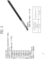
- FIG. 3 is a view showing a structural analysis result for the corner portion of the liquefied gas storage tank according to the first embodiment of the present invention
- FIG. 4 is a view showing another structural analysis result for the corner portion of the liquefied gas storage tank according to the first embodiment of the present invention.
- the vessel equipped with the liquefied gas storage tank 1 to be described below has a concept including offshore structures for performing specific tasks by floating at a certain point in the sea in addition to commercial vessels for transporting cargo from a departure to a destination.
- the liquefied gas storage tank 1 in the present invention includes any type of tank for storing liquefied gas.
- the liquefied gas storage tank 1 may be provided on a vessel to store liquefied gas, such as LNG that is a cryogenic (about -160 °C to -170 °C) substance, and may include a planar structure and a corner structure.
- liquefied gas such as LNG that is a cryogenic (about -160 °C to -170 °C) substance
- horizontal walls in a front-rear direction, a floor between the horizontal walls, a vertical wall, and a ceiling of the liquefied gas storage tank 1 may correspond to the planar structure.
- a structure in which the horizontal walls, the floor, the vertical wall, and the ceiling of the liquefied gas storage tank 1 meet may correspond to the corner structure.
- the corner structure may include an obtuse angle corner structure or a right angle comer structure. When a thickness of a primary insulation wall 3 or a secondary insulation wall 5 is changed, the obtuse angle corner structure
- the planar structure of the liquefied gas storage tank 1 may be formed in a combination of a plurality of planar blocks as shown in FIG. 1
- the corner structure of the liquefied gas storage tank 1 may be formed in a combination of a plurality of corner blocks as shown in FIG. 2
- the plurality of planar blocks may be connected to a plurality of corner blocks on a corner portion of the liquefied gas storage tank 1.
- the liquefied gas storage tank 1 may include a primary barrier 2 in contact with liquefied gas, a primary insulation wall 3 installed outside the primary barrier 2, a secondary barrier 4 installed outside the primary insulation wall 3, and a secondary insulation wall 5 disposed outside the secondary barrier 4.
- the liquefied gas storage tank 1 may be supported by a hull 7 through a mastic 6 installed between the secondary insulation wall 5 and the hull 7.
- the primary barrier 2 may include a primary flat barrier 2a in the planar block and a primary corner barrier 2b in the corner block
- the primary insulation wall 3 may include a primary flat insulation wall 3a in the planar block and a primary corner insulation wall 3b in the corner block
- the secondary barrier 4 may include a secondary flat barrier 41a in the planar block and a secondary corner barrier 41b in the corner block
- the secondary insulation wall 5 may include a secondary flat insulation wall 5a in the planar block and a secondary corner insulation wall 5b in the corner block.
- the secondary barrier 4 in the planar block and the corner block may include a flat connecting barrier 42a or a corner connecting barrier 42b connecting the adjacent secondary flat barriers 41a disposed adjacent to each other or the adjacent secondary corner barriers 41b disposed adjacent to each other.
- the primary insulation wall 3 and the secondary insulation wall 5 may be necessary to optimize thicknesses of the primary insulation wall 3 and the secondary insulation wall 5 in order to optimize insulation performance and storage capacities.
- the total of the thickness of the primary insulation wall 3 and the thickness of the secondary insulation wall 5 may be in a range of 250 mm to 500 mm, and in the embodiment, the thickness of the primary insulation wall 3 and the thickness of the secondary insulation wall 5 in the planar block and the corner block may be the same or similar.
- the thickness of the primary insulation wall in the planar block and the corner block is small that is about one-third of the thickness of the secondary insulation wall in the conventional liquefied gas storage tank
- the thickness of the primary insulation wall 3 and the thickness of the secondary insulation wall 5 in the planar block and the corner block are the same or similar, and the reason will be found by the following description.
- a planar portion of the liquefied gas storage tank 1 according to the first embodiment of the present invention will be first described with reference to FIG. 1 .
- the planar portion of the liquefied gas storage tank 1 is formed in a combination of the plurality of planar blocks, and it should be noted that a configuration of the planar block of the liquefied gas storage tank 1 to be described below is also applied to not only the first embodiment but also a second embodiment to an eighth embodiment to be described below in the same manner.
- the planar block of the liquefied gas storage tank 1 may be disposed on a planar portion of a first surface or a second surface at different angles, which forms a storage space accommodating liquefied gas, and may include the primary flat insulation wall 3a fixing the primary flat barrier 2a made of a metal material and disposed outside the primary flat barrier 2a, the secondary flat barrier 41a provided outside the primary flat insulation wall 3a, and the secondary flat insulation wall 5a disposed outside the secondary flat barrier 41a.
- the primary flat barrier 2a may be disposed on the planar portion of the first surface or the second surface at different angles to form an accommodation space accommodating the liquefied gas, which is a cryogenic substance, and may be made of a metal material.
- the metal material may be stainless steel, but is not limited thereto.
- the primary flat barrier 2a and the secondary flat barrier 41a can prevent the liquefied gas from leaking to the outside.
- the primary flat barrier 2a may be fixedly coupled to an upper portion of the primary flat insulation wall 3a by a metal strip (not shown) and installed in direct contact with the liquefied gas, which is a cryogenic substance stored in the liquefied gas storage tank 1.
- the primary flat barrier 2a seals the primary flat insulation wall 3a and the primary corner barrier 2b shown in FIG. 2 .
- the primary flat insulation wall 3a may be designed to withstand an external impact or an internal impact caused by sloshing of the liquefied gas while blocking heat penetration from the outside and installed between the primary flat barrier 2a and the secondary flat barrier 41a.
- the primary flat insulation wall 3a may have a structure in which a primary flat plywood 31a and a primary flat insulating material 32a are sequentially stacked outward from the primary flat barrier 2a and may be formed in the total of a thickness of the primary flat plywood 31a and a thickness of the primary flat insulating material 32a, for example, with a thickness of 160 mm to 250 mm, but the present invention is not limited thereto.
- the primary flat plywood 31a may be installed between the primary flat barrier 2a and the primary flat insulating material 32a.
- the primary flat insulating material 32a may be made of a material having excellent insulation performance and excellent mechanical strength to withstand the external impact or the internal impact caused by the sloshing of the liquefied gas while blocking the influence of external heat.
- the primary flat insulating material 32a may be made of polyurethane foam between the primary flat plywood 31a and the secondary flat barrier 4a and occupies most of the thickness of the primary flat insulation wall 3a.
- the primary flat insulation wall 3a, the secondary flat barrier 41a, and the secondary flat insulation wall 5a are portions of the configuration of the planar block, and the primary flat insulation wall 3a constituting the planar block may have a smaller width than the secondary flat insulation wall 5a that is another component of the planar block. Therefore, a portion of the secondary flat barrier 41a may be exposed to both sides of the primary flat insulation wall 3a.
- a flat connecting insulation wall 33a may be installed in a spatial space between the adjacent primary flat insulation walls 3a disposed adjacent to each other, that is, a spatial portion to which the secondary flat barrier 41a is exposed.
- the flat connecting insulation wall 33a may be disposed between the adjacent primary flat insulation walls 3a when the planar blocks are disposed adjacent to each other, provided in a form in which a flat connecting plywood 331a and a flat connecting insulating material 332a, which are the same as or similar to the primary flat insulation wall 3a, are stacked, and has a thickness that is the same as or similar to that of the primary flat insulation wall 3a.
- the flat connecting insulation wall 33a is installed to serve to block the influence of external heat while sealing the spatial portion formed between the adjacent secondary flat insulation walls 5a disposed adjacent to each other together with the flat connecting barrier 42a.
- the secondary flat barrier 41a may be installed between the primary flat insulation wall 3a and the secondary flat insulation wall 5a and can prevent the liquefied gas from leaking to the outside together with the primary flat barrier 2a.
- the secondary flat barrier 41a, the primary flat insulation wall 3a, and the secondary flat insulation wall 5a are portions of the configuration of the planar block, and when the planar blocks are disposed adjacent to each other, the adjacent secondary flat barriers 41a may be connected by the flat connecting barrier 42a.
- the flat connecting barrier 42a may connect the adjacent secondary flat barriers 41 exposed to the outside, and the flat connecting insulation wall 33a may be installed on the flat connecting barrier 42a.
- the secondary flat insulation wall 5a may be designed to withstand the external impact or the internal impact caused by the sloshing of the liquefied gas while blocking the influence of external heat together with the primary flat insulation wall 3a and the flat connecting insulation wall 33a.
- the secondary flat insulation wall 5a may be installed between the secondary flat barrier 4a and the hull 7 and may include a secondary flat insulating material 51a and a secondary flat plywood 52a.
- the secondary flat insulation wall 5a may have a structure in which the secondary flat insulating material 51a and the secondary flat plywood 52a are sequentially stacked outward from the secondary flat barrier 41a and may be formed to have the total of a thickness of the secondary flat insulating material 51a and a thickness of the secondary flat plywood 52a, for example, in a range of 150 mm to 240 mm that is the same as or similar to the thickness of the primary flat insulation wall 3a, but the present invention is not limited thereto.
- the secondary flat insulating material 51a may be made of a material having excellent insulation performance and excellent mechanical strength to withstand the external impact or the internal impact caused by the sloshing of the liquefied gas while blocking the influence of external heat.
- the secondary flat insulating material 51a may be made of polyurethane foam between the secondary flat barrier 41a and the secondary flat plywood 52a and occupies most of the thickness of the secondary flat insulation wall 5a.
- the secondary flat plywood 52a may be installed between the secondary flat insulating material 51a and the hull 7.
- the planar block of the liquefied gas storage tank 1 may be formed so that the flat connecting insulation wall 33a included in the primary flat insulation wall 3a has a thickness that is the same as or similar to the thickness of the secondary flat insulation wall 5a.
- the flat connecting insulating material 332a of the flat connecting insulation wall 33a may be formed to have a thickness in a range of 90% to 110% of the secondary flat insulating material 51a so that the flat connecting insulating material 332a of the flat connecting insulation wall 33a has a thickness that is the same as or similar to that of the secondary flat insulating material 51a.
- the thickness of the primary flat insulation wall 3a and the thickness of the secondary flat insulation wall 5a are formed identically or similarly to each other, which is to prevent damage caused by a low-temperature stress of the secondary flat insulation wall 41a.
- the secondary flat barrier 41a and the secondary flat insulation wall 5a have a difference in contraction depending on a temperature to which the secondary flat barrier 41a and the secondary flat insulation wall 5a are exposed, and the secondary flat barrier 41a and the secondary flat insulation wall 5a may be more affected by the cooling or heating of the cryogenic liquefied gas as the thickness of the flat connecting insulation wall 33a becomes smaller.
- the secondary flat barrier 41a and the secondary flat insulation wall 5a may be more affected by the cooling or heating of the cryogenic liquefied gas as the thickness of the flat connecting insulation wall 33a becomes smaller.
- a risk of damage to the secondary flat barrier 41a increases because a temperature of the secondary flat barrier 41a is reduced and the contraction thereof increases, and thus the stress at low temperature increases.
- the problem may occur mainly in the flat connecting barrier 42a interconnecting the secondary flat barriers 41a by bonding or the like under the flat connecting insulation wall 33a.
- Both ends of the flat connecting barrier 42a under the flat connecting insulation wall 33a are connected to the secondary flat barriers 41a in the plurality of planar blocks disposed adjacent to each other because the flat connecting barrier 42a may be deformed so that both ends of the flat connecting barrier 42a move away from each other or are close to each other as the secondary flat insulation wall 5a in the planar block contracts.
- the thicknesses of the primary flat insulation wall 3a including the flat connecting insulation wall 33a and the secondary flat insulation wall 5a identically or similarly to each other, it is possible to reduce the cryogenic loads of the flat connecting barrier 42a, particularly, as well as the secondary barrier 41a as the thickness of the primary flat insulation wall 3a including the flat connecting insulation wall 33a is relatively greater than the conventional one and also reduce the contraction of the secondary flat insulation wall 5a as the thickness of the secondary flat insulation wall 5a is relatively smaller than the conventional one, thereby reducing the stress at low temperature.
- the risk of damage to the secondary barrier 4 in a portion in which the plurality of planar blocks are disposed adjacent to each other becomes relatively lower than the conventional one.
- the corner portion of the liquefied gas storage tank 1 will be described with reference to FIG. 2 .
- the corner portion of the liquefied gas storage tank 1 may be formed in a combination of a plurality of corner blocks.
- an obtuse angle corner structure at an angle of 135° will be described as an example, but the present invention is not limited to the value.
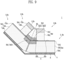
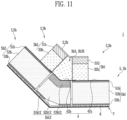
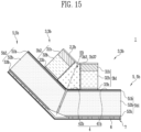
- the corner block of the liquefied gas storage tank 1 may be disposed at the corner portion in which the first surface and the second surface at different angles that form the storage space accommodating the liquefied gas and meet each other and may include the primary corner insulation wall 3b fixing the primary corner barrier 2b made of a metal material and disposed outside the primary corner barrier 2b, the secondary corner barrier 41b provided outside the primary corner insulation wall 3b, and the secondary corner insulation wall 5b disposed outside the secondary corner barrier 41b.
- the primary corner insulation wall 3b may further include an inner bent portion 3b3.
- the primary corner barrier 2b may be disposed at the corner portion in which the first surface and the second surface at different angles meet each other to form the accommodation space accommodating the liquefied gas, which is a cryogenic substance, and may be made of a metal material.
- the primary corner barrier 2b and the secondary corner barrier 41b can prevent the liquefied gas from leaking to the outside.
- the primary corner barrier 2b may be fixedly coupled to the primary corner insulation wall 3b by a barrier fixing member installed on an upper end of the primary corner insulation wall 3b in various methods, such as a bonding or bolting method, and installed in direct contact with the liquefied gas, which is the cryogenic substance stored in the liquefied gas storage tank 1. Therefore, the primary corner barrier 2b to be described below may be used as the meaning including the barrier fixing member or the like.
- the primary corner barrier 2b may seal the primary corner insulation wall 3b and the primary flat barrier 2a shown in FIG. 1 and may be fixed to a primary inner plywood 31b of a first inner fixing unit 3b1 and a primary inner plywood 31b of a second inner fixing unit 3b2 and provided to be bent from an inner surface of an insulating material 3b31 of the inner bent portion 3b3 at a predetermined angle, for example, an angle of 135°.
- the primary corner insulation wall 3b may be designed to withstand an external impact or an internal impact caused by the sloshing of the liquefied gas while blocking the influence of external heat and installed between the primary corner barrier 2b and the secondary corner barrier 41b.
- the primary corner insulation wall 3b may be provided inside each of the first surface and the second surface and may include the first inner fixing unit 3b1 and the second inner fixing unit 3b2 formed in a structure in which the primary inner plywood 31b, the primary corner insulating material 32b, and the primary outer plywood 33b are sequentially stacked outward from the primary corner barrier 2b.
- first inner fixing unit 3b1 may be fixed to a primary outer fixing unit 5b1 and provided inside the first surface
- second inner fixing unit 3b2 may be fixed to a secondary outer fixing unit 5b2 and provided inside the second surface.
- the primary corner insulation wall 3b may include the inner bent portion 3b3 formed by filling a space between the first inner fixing unit 3b1 and the second inner fixing unit 3b2 with an insulating material 3b31.
- the primary corner insulation wall 3b may be formed so that the total of a thickness of the primary inner plywood 31b, a thickness of the primary corner insulating material 32b, and a thickness of the primary outer plywood 33b is the same as the thickness (e.g., the thickness in a range of 160 mm to 250 mm) of the primary flat insulation wall 3a.
- the primary inner plywood 31b may be installed between the primary corner barrier 2b and the primary corner insulating material 32b.
- the primary insulation wall 3 in the planar block and the corner block is formed to have a relatively greater thickness than the conventional primary insulation wall, it is possible to reduce the thickness of the primary inner plywood 31b constituting the primary corner insulation wall 3b in the corner block and replace the remaining thickness with the primary corner insulating material 32b made of polyurethane foam.
- the thickness of the primary inner plywood 31b in the embodiment may be in a range of 20 mm to 80 mm.
- the first and second inner fixing units 3b1 and 3b2 for holding the barrier fixing member to which the primary corner barrier 2b of the corner block is fixed which are made of a component combined with the primary corner insulating material 32b made of the polyurethane foam rather than being made of only the plywood having a thickness of about 92 mm like the conventional one, it is possible to increase insulation performance, reduce a weight, and reduce costs compared to the conventional one made of only the plywood.
- the primary corner insulation material 32b may be disposed between the primary inner plywood 31b and the primary outer plywood 33b and made of high-density polyurethane foam, which is a material having excellent insulation performance and excellent mechanical strength, to withstand the external impact or the internal impact caused by the sloshing of the liquefied gas while blocking the influence of external heat.
- the primary outer plywood 33b may be disposed between the primary corner insulating material 32b and the secondary corner barrier 41b and fixed to the secondary corner barrier 41b.
- the primary outer plywood 33b may be formed with a thickness of 6.5 mm to 15 mm.
- the primary corner insulation wall 3b in the embodiment is formed in the structure in which the primary inner plywood 31b, the primary corner insulating material 32b, and the primary outer plywood 33b are sequentially stacked
- the primary inner plywood 31b and the primary outer plywood 33b having a high strength may hold the heat contraction of the primary corner insulating material 32b so that the heat contraction of the primary corner insulating material 32b is not directly applied to the secondary barriers 4 (41b and 42b) between the first and second outer fixing units 5b1 and 5b2
- the primary corner insulating material 32b may be provided as an intermediate layer, thereby easily controlling tolerances of the primary inner plywood 31b and the primary outer plywood 33b sensitive to humidity.
- the first and second inner fixing units 3b1 and 3b2 constituting the primary corner insulation wall 3b are each fixed to the secondary corner insulation wall 41b and the first and second outer fixing units 5b1 and 5b2 constituting the secondary corner insulation wall 5b, and a width of each of the first and second inner fixing units 3b1 and 3b2 may be smaller than a width of each of the first and second outer fixing units 5b1 and 5b2.
- the insulating material 3b31 of the inner bent portion 3b3 may be made of low-density polyurethane foam, and the secondary barrier 4 in which the secondary corner barrier 41b and the corner connecting barrier 42b are stacked may be provided on an outer surface bent at a predetermined angle, for example, an angle of 135°.
- the insulating material 3b31 of the inner bent portion 3b3 may serve to block the influence of external heat while sealing the spatial portion formed between the adjacent first and second outer fixing units 5b1 and 5b2 disposed adjacent to each other together with the corner connecting barrier 42b.
- the secondary corner barrier 41b may be provided outside the primary corner insulation wall 3b.
- the secondary corner barrier 41b may be installed between the primary corner insulation wall 3b and the secondary corner insulation wall 5b and can prevent the liquefied gas from leaking to the outside together with the primary corner barrier 2b.
- the secondary corner barrier 41b, the primary corner insulation wall 3b, and the secondary corner insulation wall 5b are portions of the configuration of the corner block, and when the corner blocks are disposed adjacent to each other, the adjacent secondary barriers 41b between the first and second outer fixing units 5b1 and 5b2 may be connected by the corner connecting barrier 42b.
- the secondary barrier 4 in which the secondary corner barrier 41b and the corner connecting barrier 42b are stacked may be provided to be bent.
- the secondary corner insulation wall 5b may be disposed outside the secondary corner barrier 41b.
- the secondary corner insulation wall 5b may be designed to withstand the external impact or the internal impact caused by the sloshing of the liquefied gas while blocking the influence of external heat together with the primary corner insulation wall 3b and the insulating material 3b31 of the inner bent portion 3b3.
- the secondary corner insulation wall 5b may be installed between the secondary corner barrier 4b and the hull 7 and may include a secondary inner plywood 51b, a secondary corner insulating material 52b, and a secondary outer plywood 53b.
- the secondary corner insulation wall 5b may be fixed inside each of the first surface and the second surface and may include the first outer fixing unit 5b 1 and the second outer fixing unit 5b2 formed in a structure in which the second inner plywood 51b, the secondary corner insulating material 52b, and the secondary outer plywood 53b are sequentially stacked outward from the secondary corner barrier 2b.
- Side surfaces in which the first outer fixing unit 5b1 fixed to the first surface and the second outer fixing unit 5b2 fixed to the second surface face each other may be provided to be inclined in a direction ED in which the corner portion is equally divided.
- the corner portion has been described as being equally divided but the present invention is not limited thereto, and since the corner portion may not be equally divided according to a corner position, it goes without saying that the corner portion may be provided to be inclined in the direction ED in which the corner portion is unequally divided.
- the secondary corner insulation wall 5b may be formed so that the total of a thickness of the secondary inner plywood 51b, a thickness of the secondary corner insulating material 52b, and a thickness of the secondary outer plywood 53b is the same as the thickness (e.g., the thickness in a range of150 mm to 240 mm) of the secondary flat insulation wall 5a.
- the secondary inner plywood 51b may be disposed between the secondary corner barrier 2b and the secondary corner insulating material 51b, and the secondary corner barrier 2b may be fixed thereto.
- the secondary inner plywood 51b may be formed with a thickness 6.5 mm to 15 mm.
- the secondary corner insulating material 52b may be made of a material having excellent insulation performance and excellent mechanical strength to withstand the external impact or the internal impact caused by the sloshing of the liquefied gas while blocking the influence of external heat.
- the secondary corner insulating material 52b may be made of polyurethane foam between the secondary inner plywood 51b and the secondary outer plywood 53b and occupies most of the thickness of the secondary corner insulation wall 5b.
- the secondary outer plywood 53b may be installed between the secondary corner insulation material 52b and the hull 7.
- the secondary outer plywood 53b may be formed with a thickness of 6.5 mm to 25 mm.
- the secondary barrier 4 in the corner block as well as in the planar block moves toward the hull 7, thereby increasing a curvature radius thereof, and in this case, as the curvature radius of the secondary barrier 4 at the corner portion increases, a length of a portion in which the secondary barrier 4 is not attached to the secondary insulation wall 5 also increases.
- the flexibility of the secondary barrier 4 in the obtuse angle comer structure increases, and thus in the secondary barrier 4 in the obtuse angle comer structure, the deformation of nearby portions, for example, the deformation of the hull is easily absorbed, and the low-temperature stress is also reduced.
- the length of the non-adhesive portion may be, for example, in a range of 0 mm to 100 mm, and preferably, 50 mm to 100 mm.
- the stress at low temperature applied to the conventional secondary barrier 4 can be more reduced than in the obtuse angle corner structure of the primary insulation wall 3 formed in a relatively smaller thickness.
- the non-adhesive portion increases, the deformation of the hull can also be easily absorbed.
- heat transfer analysis was performed assuming that the temperature was 20 °C at a position of the hull and - 163 °C in the primary barrier, and the structural analysis was performed using a temperature distribution derived by this result.
- the conventional liquefied gas storage tank for comparing the result obtained by the structural analysis of the liquefied gas storage tank 1 according to the embodiment is a case in which the thickness of the primary insulation wall in the planar block and the corner block was small that is one-third of the thickness of the secondary insulation wall, the fixing members corresponding to the first and second inner fixing units 3b1 and 3b2 were made of only plywood, and the length of the non-adhesive portion was 50 mm, and in the conventional liquefied gas storage tank, a stress value of the bent portion of the secondary barrier in a YY direction was about 66.8984 MPa, and a temperature thereof was about -135.857 °C.
- the stress value in the YY direction obtained as a result of the structural analysis is a stress value at the corner, the smaller the stress value, the less the stress, and the temperature is the temperature at the corner, the higher the temperature, the less the stress (indicating a value changed after installation at room temperature 25 °C).
- FIG. 3 shows a result of structural analysis for a stress value in the YY direction and a temperature distribution of the secondary barrier 4 (41b and 42b) at a bent portion at which the first and second outer fixing units 5b1 and 5b2 face each other when the length of the non-adhesive portion in the embodiment was 50 mm, and the stress value in the YY direction was 37.155 MPa, and the temperature was -57.940 °C.
- the stress in the secondary barrier 4 (41b and 42b) according to the embodiment is much less, which means a reduction in the effect due to the cooling or heating from the cryogenic substance, such as damage to the secondary barrier 4 (41b and 42b) caused by the low-temperature stress, in the embodiment compared to the conventional one.
- FIG. 4 shows a result of structural analysis for a stress value in the YY direction and a temperature distribution of the secondary barrier 4 (41b and 42b) at a bent portion at which the first and second outer fixing units 5b1 and 5b2 face each other when the length of the non-adhesive portion in the embodiment was 97 mm, and the stress value in the YY direction was 12.084 MPa, and the temperature thereof was -59.025 °C.
- the stress in the secondary barrier 4 (41b and 42b) according to the embodiment is much less, which means a reduction in the effect due to the cooling or heating from the cryogenic substance, such as damage to the secondary barrier 4 (41b and 42b) caused by the low-temperature stress, in the embodiment compared to the conventional one.
- the first and second inner fixing units 3b1 and 3b2 for holding the barrier fixing member to which the primary corner barrier 2b in the corner block is fixed which are made of a component combined with the insulating material 3b31 made of the polyurethane foam rather than being made of only the plywood, it is possible to increase insulation performance, reduce the weight, and reduce the cost compared to the conventional one made of only the plywood.
- the thickness of the primary corner insulation wall 3b in the corner block connected to the primary flat insulation wall 3a in the planar block and the secondary corner insulation wall 5b in the corner block connected to the secondary flat insulation wall 5a in the planar block becomes relatively greater (however, the thickness of the secondary corner insulation wall 5b is the thickness at which the mechanical strength may be maintained at a predetermined level), it is possible to reduce the low-temperature load and sloshing load of the secondary barrier 4 (41b and 42b) between the first and second outer fixing units 5b1 and 5b2 and not only prevent the damage to the secondary barrier 4 (41b and 42b) but also reduce the low-temperature load of the secondary barrier 4 (41b and 42b), thereby preventing brittle fracture of the hull 7.
- the thickness of the primary corner insulation wall 3b relatively greater than the conventional one, it is possible to increase the length of the portion in which the secondary barrier 4 (41b and 42b) is not attached to the secondary corner insulation wall 5b, thereby not only further reducing the probability of the damage to the secondary barrier 4 (41b and 42b) by an increase in the flexibility of the secondary barrier 4 (41b and 42b), but also easily absorbing the deformation of the hull and also further reducing the low-temperature stress in the secondary barrier 4 (41b and 42b).
- FIG. 5 is a cross-sectional view of a corner portion for describing a liquefied gas storage tank according to a second embodiment of the present invention
- FIG. 6 is a view showing a structural analysis result for the corner portion of the liquefied gas storage tank according to the second embodiment of the present invention.
- the planar structure of the liquefied gas storage tank 1 in the embodiment may be formed in a combination of the plurality of planar blocks as shown in FIG. 1
- the corner structure of the liquefied gas storage tank 1 may be formed in a combination of the plurality of corner blocks as shown in FIG. 5
- the plurality of planar blocks may be connected to a plurality of corner blocks on a corner portion of the liquefied gas storage tank 1.
- a configuration of the planar block is the same as or similar to the configuration described above with reference to FIG. 1 .
- the planar block of the liquefied gas storage tank 1 in the embodiment may be disposed on the planar portion of the first surface or the second surface at difference angles, which forms the storage space accommodating liquefied gas, and may include the primary flat insulation wall 3a fixing the primary flat barrier 2a made of a metal material and disposed outside the primary flat barrier 2a, the secondary flat barrier 41a provided outside the primary flat insulation wall 3a, and the secondary flat insulation wall 5a disposed outside the secondary flat barrier 41a.
- the liquefied gas storage tank 1 may include the primary barrier 2 in contact with the liquefied gas, the primary insulation wall 3 installed outside the primary barrier 2, the secondary barrier 4 installed outside the primary insulation wall 3, and the secondary insulation wall 5 disposed outside the secondary barrier 4.
- the liquefied gas storage tank 1 may be supported by a hull 7 through a mastic 6 installed between the secondary insulation wall 5 and the hull 7.
- the liquefied gas storage tank 1 may include the primary barrier 2 in contact with the liquefied gas, the primary insulation wall 3 installed outside the primary barrier 2, the secondary barrier 4 installed outside the primary insulation wall 3, and the secondary insulation wall 5 disposed outside the secondary barrier 4.
- the liquefied gas storage tank 1 may be supported on the hull 7 by the mastic 6 installed between the secondary insulation wall 5 and the hull 7.
- the lower block LB in the embodiment may be the same as or similar to the configuration of at least any one of the first to eighth embodiments, here, a detailed description thereof will be omitted to avoid overlapping descriptions.
- the upper block UB may have the plurality of unit upper blocks, for example, the first to fourth unit upper blocks UB1, UB2, UB3, and UB4 side by side disposed adjacent to one another and may have the lower surface bonded on the lower block LB and an upper surface fixed to the barrier fixing member 21b.
- the primary corner insulation wall 3b may be provided inside each of the first surface and the second surface and may include the first inner fixing unit 3b1 and the second inner fixing unit 3b2 formed in a structure in which the primary inner plywood 31b, the primary corner insulating material 32b, and the primary outer plywood 33b are sequentially stacked outward from the barrier fixing member 21b.
- the second inner fixing unit 3b1 and the second inner fixing unit 3b2 may be symmetrically provided with respect to the direction ED in which the corner portion is equally divided.
- a side surface of the first inner half bent portion 3b3' having the triangular shape may be perpendicular to the corner connecting barrier 42b of the secondary barrier 4 and bonded and connected to a side surface of the first inner fixing unit 3b1 by a first bonding unit 3b6.
- a side surface of the second inner half bent portion 3b3" having the triangular shape may be perpendicular to the corner connecting barrier 42b of the secondary barrier 4 and bonded and connected to a side surface of the second inner fixing unit 3b2 by a second bonding unit 3b7.
- each of the first inner fixing unit 3b1, the second inner fixing unit 3b2, the first inner half bent portion 3b3', and the second inner half bent portion 3b3" that are formed as four divided pieces may be provided.
- the first inner fixing unit 3b1 and the first inner half bent portion 3b3' may be bonded using the first bonding unit 3b6.
- the second inner fixing unit 3b2 and the second inner half bent portion 3b3" are bonded using the second bonding unit 3b7.
- the first inner fixing unit 3b1 bonded and connected to the first inner half bent portion 3b3' is bonded and connected to the secondary barrier 4 using an adhesive 10.
- the second inner fixing unit 3b2 bonded and connected to the second inner half bent portion 3b3" is bonded and connected to the secondary barrier 4 using the adhesive 10.
- the assembly is completed by inserting and installing a first corner inner packing material 3b8 into the space between the first inner half bent portion 3b3' and the second inner half bent portion 3b3" formed by the bonding with the second barrier 4.
- the primary corner insulation wall 3b in the embodiment may further include the first corner inner packing material 3b8 for sealing the space between the first and second inner half bent portions 3b3' and 3b3".
- the first corner inner packing material 3b8 may be formed of a vacuum insulation material using glass wool as a main raw material.
- first corner inner packing material 3b8 may be formed to have a positive (+) tolerance to seal the space in the state of being inserted into the space between the first and second inner half bent portions 3b3' and 3b3".
- chamfers may be formed at right angle corner portions in which side surfaces and bottom surfaces of the first and second inner half bent portions 3b3' and 3b3" meet each other as the squeeze-out checking device.
- the barrier fixing member 21b may be made of a metal material and installed on the primary corner insulation wall 3b.
- the inner bent portion 3b3 of the primary corner insulation wall 3b formed of the first inner half bent portion 3b3' bonded and connected to the first inner fixing unit 3b1 and the second inner half bent portion 3b3' bonded and connected to the second inner fixing unit 3b2 it is possible to block heat convection paths between the first inner fixing unit 3b 1 and the first inner half bent portion 3b3' and between the second inner fixing unit 3b2 and the second inner half bent portion 3b3" even when the first and second inner half bent portions 3b3' and 3b3" expand or contract, thereby preventing the heat convection phenomenon in the inner bent portion 3b3.
- the chamfers CF on the right angle corner portions in which the side surfaces and bottom surfaces of the first and second inner half bent portions 3b3' and 3b3" meet each other, it is possible to directly and visually check that the adhesive 10 in the adhesive region is squeezed out to the non-adhesive region when the primary outer plywoods 53b of the first and second inner fixing units 3b1 and 3b2 are attached to the corner connecting barrier 42b of the secondary barrier 4 with the adhesive 10, thereby preventing a bonding defect.
- the upper connecting block UBB in the embodiment may be bonded and connected to upper surfaces of the lower blocks LB disposed adjacent to each other to connect the lower blocks LB.
- the upper connecting block UBB may be installed in a space exposed between the upper block UB formed of the first to fourth unit upper blocks UB1, UB2, UB3, and UB4 side by side disposed adjacent to each other and the upper block UB disposed adjacent thereto.
- the upper connecting block UBB may be formed of the corner connecting insulation wall 34b disposed outside the barrier fixing member 21b.
- the corner connecting insulation wall 34b of the upper connecting block UBB may be designed to withstand the external impact or the internal impact caused by the sloshing of the liquefied gas while blocking the influence of external heat together with the primary corner insulation wall 3b and installed between the barrier fixing member 21b and the corner connecting barrier 42b.
- the corner connecting insulation wall 34b may be provided inside each of the first surface and the second surface and may include the first corner connecting fixing unit 34b1 and the second corner connecting fixing unit 34b2 formed in a structure in which the first corner connecting plywood 342b, the corner connecting insulating material 341b, and the second corner connecting plywood 343b are sequentially stacked outward from the barrier fixing member 21b.
- the first corner connecting fixing unit 34b 1 and the second corner connecting fixing unit 34b2 may be symmetrically provided with respect to the direction ED in which the corner portion is equally divided.
- corner connecting insulation wall 34b may include a corner connecting bent portion 34b3 installed in the corner spatial portion between the first corner connecting fixing unit 34b 1 and the second corner connecting fixing unit 34b2 and formed of an insulating material.
- the corner connecting bent portion 34b3 in the embodiment may be formed to be divided into a first corner half bent portion 34b3' and a second corner half bent portion 34b3" unlike the conventional integrated inner bent portion.
- a side surface of the first corner half bent portion 34b3' may be perpendicular to the corner connecting barrier 42b of the secondary barrier 4 and bonded and connected to a side surface of the first corner connecting fixing unit 34b1 by a first bonding unit 34b6.
- a side surface of the second corner half bent portion 34b3" may be perpendicular to the corner connecting barrier 42b of the secondary barrier 4 and bonded and connected to a side surface of the second corner connecting fixing unit 34b2 by a second bonding unit 34b7.
- the corner connecting insulation wall 34b in the embodiment may further include a second corner inner packing material 34b8 for sealing the space between the first and second corner half bent portions 34b3' and 34b3".
- each of the first corner half bent portion 34b3', the second corner half bent portion 34b3", and the second corner inner packing material 34b8 in the upper connecting block UBB and each of the first inner half bent portion 3b3', the second inner half bent portion 3b3", and the first corner inner packing material 3b8 in the upper block UB have only different reference numerals and names and may have configurations that are the same or similar, here, a detailed description thereof will be omitted to avoid overlapping descriptions.
- FIG. 23 is a partial front view of a corner portion for describing a liquefied gas storage tank according to a tenth embodiment of the present invention
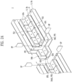
- FIG. 24 is a partially exploded perspective view of the corner portion for describing the liquefied gas storage tank according to the tenth embodiment of the present invention
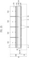
- FIG. 25 is a front view showing an integrated upper block in FIG. 23
- FIG. 26 is a front view showing another sample of the integrated upper block in FIG. 25
- FIG. 27 is a side view of the integrated upper block in FIG. 25
- FIG. 28 is a cross-sectional view along line A-A' in FIG. 25
- FIG. 29 is a perspective view showing the upper connecting block in FIG. 23
- FIG. 30 is a front view showing the upper connecting block in FIG. 23
- FIG. 31 is a cross-sectional view along line B-B' in FIG. 30
- FIG. 32 is a cross-sectional view showing still another sample of the integrated upper block in FIG. 25 .
- FIG. 33 is an exploded view of the integrated upper block in FIG. 32
- FIGS. 34 to 37 are views showing a comparison of convection paths and temperatures of secondary barriers that vary depending on structures of primary corner insulation walls and corner connecting insulation walls in the liquefied gas storage tank according to the tenth embodiment of the present invention and a liquefied gas storage tank according to a comparative example.
- the corner portion of the liquefied gas storage tank 1 may be formed in a combination of a plurality of corner blocks CB.
- a primary structure of the corner block CB may include a lower block LB fixed to the hull 7 and formed of a single board, an integrated upper block UUB bonded on the lower block LB and having widths smaller than front-rear and left-right widths of the lower block LB, and an upper connecting block UBB connecting the lower blocks LB disposed adj acent to each other and bonded and connected to the secondary barrier 4 exposed between the integrated upper blocks UUB disposed adjacent to each other.
- the corner block CB divided into the lower block LB, the integrated upper block UUB, and the upper connecting block UBB in the embodiment will be described below in detail.
- a configuration of the embodiment may be the same as or similar to those of the above-described ninth embodiment or those of the first to eight embodiments, and in this case, a detailed description thereof will be omitted to avoid overlapping descriptions.
- the lower block LB may have the integrated upper block UUB and the upper connecting block UBB installed on an upper surface thereof and may include the secondary corner barrier 41b bonded and connected to a lower surface of the integrated upper block UUB, the corner connecting barrier 42b connecting the adjacent secondary corner barriers 41b exposed to the outside because the integrated upper block UUB is not installed thereon when the lower blocks LB are disposed adjacent to each other and bonded and connected to a lower surface of the upper connecting block UBB, and the secondary corner insulation wall 5b including the secondary inner plywood 51b, the secondary corner insulating material 52b, and the secondary outer plywood 53b.
- a configuration of the lower block LB in the embodiment may be the same as or similar to that of at least one embodiment of the first to ninth embodiments, here, a detailed description thereof will be omitted to avoid overlapping descriptions.
- the integrated upper block UUB may be bonded on the lower block LB and formed of the single board having the widths smaller than the front-rear and left-right widths of the lower block LB.
- the integrated upper block UUB may be formed of the single board by integrating a plurality of unit upper blocks into one compared to the conventional upper blocks having the plurality of unit upper blocks side by side disposed adjacent to each other.
- the conventional upper block may have the four first to fourth unit upper blocks UB1, UB2, UB3, and UB4 side by side disposed adjacent to each other
- the integrated upper block UUB in the embodiment may be formed of the single board having the widths smaller than the front-rear and left-right widths of the conventional upper block UB having the first to fourth unit upper blocks UB1, UB2, UB3, and UB4 side by side disposed adjacent to each other.
- the integrated upper block UUB is described as being formed in a size in which the four first to fourth unit upper blocks UB 1, UB2, UB3, and UB4 are integrated but the present invention is not limited thereto, and it goes without saying that the integrated upper block UUB may be formed in a size in which two or more unit upper blocks are integrated.
- the integrated upper block UUB may be formed of the primary corner insulation wall 3b including the first inner fixing unit 3b1 and the second inner fixing unit 3b2 formed in the single board structure in which one primary inner plywood 31b, one primary corner insulating material 32b, and one primary outer plywood 33b are sequentially stacked outward from the barrier fixing member 21b formed of a plurality of unit barrier fixing members 21b1, 21b2, 21b3, and 21b4.
- the second inner fixing unit 3b1 and the second inner fixing unit 3b2 may be symmetrically provided with respect to the direction ED in which the corner portion is equally divided.
- the first and second inner fixing units 3b1 and 3b2 formed in the single board structure will be described below but may be fixed by the plurality of unit barrier fixing members 21b1, 21b2, 21b3, and 21b4.
- the integrated upper block UUB having the plurality of unit upper blocks UB1, UB2, UB3, and UB4 integrated into one compared to the conventional upper block UB having the plurality of unit upper blocks UB1, UB2, UB3, and UB4 side by side disposed adjacent to each other it is possible to omit the heat convection paths generated between the conventional unit upper blocks UB1, UB2, UB3, and UB4, thereby reducing the heat convection phenomenon.
- the primary corner insulation wall 3b may include the inner bent portion 3b3 installed in the corner spatial portion between the first inner fixing unit 3b 1 and the second inner fixing unit 3b2 and formed of the insulating material.
- the inner bent portion 3b3 in the embodiment may have a reduced size that is about half of the sizes of the first and second inner fixing units 3b 1 and 3b2 of the primary corner insulation wall 3b and have a symmetrical shape with respect to the direction ED in which the corner portion is equally divided.
- the inner bent portion 3b3 having the reduced size is described as being applied to the integrated upper block UUB having the plurality of unit upper blocks UB1, UB2, UB3, and UB4 integrated into one but the present invention is not limited thereto, and it goes without saying that the inner bent portion 3b3 may also be applied to the conventional upper block UB having the plurality of unit upper blocks UB1, UB2, UB3, and UB4 side by side disposed adjacent to each other.
- both side surfaces of the inner bent portion 3b3 having the reduced size which are perpendicular to the corner connecting barrier 42b of the secondary barrier 4 inside the first surface and the second surface, may each have a height that is about half the total height of each of the first and second inner fixing units 3b 1 and 3b2, for example, sizes in a range of 40% to 60% of the total height of the first and second inner fixing units 3b 1 and 3b2.
- the shapes of the side surfaces of the first and second inner fixing units 3b 1 and 3b2 may be changed.
- first and second inner fixing units 3b 1 and 3b2 in the embodiment may be symmetrically provided with respect to the direction ED in which the corner portion is equally divided, first side surfaces of the first and second inner fixing units 3b 1 and 3b2 in close contact with both side surfaces of the inner bent portion 3b3 having the reduced size may be perpendicular to the corner connecting barrier 42b of the secondary barrier 4, and second side surfaces extending inward (toward the storage space) from the perpendicular first side surfaces may extend in the same direction as the direction ED of the division.
- the primary corner insulation wall 3b in the embodiment may be assembled by fixing the primary outer plywoods 53b of the first and second inner fixing units 3b 1 and 3b2 to the corner connecting barriers 42b of the secondary barrier 4 with the adhesive 10 in a state in which the second side surface of the first inner fixing unit 3b 1 and the second side surface of the second inner fixing unit 3b2 are formed to face each other and inserting and installing the inner bent portion 3b3 having the reduced size into the corner space formed by the first and second inner fixing units 3b 1 and 3b2.
- the primary corner insulation wall 3b in the embodiment may further include the corner inner packing material 3b8 for sealing the space between the second side surfaces of the first and second inner fixing units 3b 1 and 3b2.
- the corner inner packing material may be formed of a vacuum insulating material using glass wool as a main raw material.
- corner inner packing material 3b8 may be formed to have a positive (+) tolerance to seal the space in a state of being inserted into the space between the second side surfaces of the first and second inner fixing units 3b 1 and 3b2.
- the corner inner packing material 3b8 may be formed to be inserted into the inner bent portion 3b3 having the reduced size at a predetermined depth.
- An insertion groove SH may be formed at a point at which both side surfaces of the inner bent portion 3b3 meet each other in the same direction as the division direction ED at a predetermined depth.
- the insertion groove SH may be formed in a direction corresponding to the corner side of the storage tank, and a depth of the insertion groove SH may be smaller than or equal to half the thickness of the inner bent portion 3b3, but the present invention is not limited thereto.
- the embodiment not only by reducing the size of the inner bent portion 3b3, it is possible to reduce the space (the non-adhesive region in the corner portion between the inner bent portion and the secondary barrier) in which the heat convection is generated, but also by forming the corner inner packing material 3b8 between the second side surfaces of the first and second inner fixing units 3b 1 and 3b2 in a state in which the first side surfaces and the second side surfaces of the first and second inner fixing units 3b 1 and 3b2, which may be the heat convection paths, are bent, it is possible to reduce a reduced area due to a change in temperature compared to the conventional inner bent portion formed at the same height as the first and second inner fixing units 3b 1 and 3b2, thereby reducing the heat convection phenomenon.
- the inner bent portion 3b3 having the reduced size in the embodiment may have first protrusions PT1 provided on both side surfaces thereof.
- the first protrusion PT1 may extend outward from the corner spatial portion as much as a predetermined length from the inner bent portion 3b3 inserted into the corner spatial portion formed by the first and second inner fixing units 3b1 and 3b2.
- the first protrusion PT1 may have a cross-sectional shape which is similar to a shape of the inner bent portion 3b3 and in which a curved portion, which is in contact with the corner connecting barrier 42b of the secondary barrier 4, collinearly extends from the curved portion of the inner bent portion 3b3 and extend to form first steps ST1 between both side surfaces that are perpendicular to the corner connecting barrier 42b of the secondary barrier 4 and both side surfaces of the inner bent portion 3b3.
- the integrated upper block UUB in the embodiment may include a plurality of upper slits SL1 formed in an upper portion thereof at a predetermined depth in order to cope with contraction and expansion stresses of the primary corner insulation wall 3b having the single board structure.
- the upper slit SL1 may have a depth that is smaller than or equal to half the thickness of the primary corner insulation wall 3b constituting the integrated upper block UUB, for example, a depth in a range of 30% to 50% of the thickness of the primary corner insulation wall 3b.
- the upper slit SL1 pass through the primary inner plywood 31b, which is an upper layer of the primary corner insulation wall 3b, and be formed to at least a portion of the primary corner insulating material 32b, which is an intermediate layer, to cope with the contraction or expansion stress of the primary corner insulating material 32b.
- the upper slit SL1 By forming the upper slit SL1 at the depth corresponding to the thickness that is smaller than or equal to half the thickness of the primary corner insulation wall 3b, it is possible to not only maximally mitigate the contraction or expansion stress caused by the temperature applied to the primary corner insulation wall 3b, but also reduce the heat convection space and prevent cold air from being transmitted from the corner block CB to the planar block by the insulating material (not shown) formed between the primary flat insulation wall 3a in the planar block shown in FIG. 1 and the primary corner insulation wall 3b in the corner block CB in the embodiment.
- the upper slits SL1 in the embodiment may be formed at corresponding positions between the plurality of unit barrier fixing members 21b 1, 21b2, 21b3, and 21b4 installed on the upper surface of the integrated upper block UUB of the portion corresponding to each of the plurality of unit upper blocks UB 1, UB2, UB3, and UB4 constituting the conventional upper block UB and the present invention is not limited to these positions, and it goes without saying that the upper slits SL1 may be formed at any position spaced a predetermined distance from each other.
- the integrated upper block UUB in the embodiment may include a plurality of lower slits SL2 formed in a lower portion of the integrated upper block UUB at a predetermined depth to cope with the contraction or expansion stress of the primary corner insulation wall 3b having the single board structure.
- the lower slit SL2 may have a depth that is smaller than or equal to half the thickness of the primary corner insulation wall 3b constituting the integrated upper block UUB, for example, a depth in a range of 30% to 50% of the thickness of the primary corner insulation wall 3b.
- the lower slit SL1 pass through the primary inner plywood 3 1b, which is a lower layer of the primary corner insulation wall 3b, and be formed to at least a portion of the primary corner insulating material 32b, which is an intermediate layer, to cope with the contraction or expansion stress of the primary corner insulating material 32b.
- the lower slits SL2 in the embodiment may be formed at positions formed to be misaligned with the upper slits SL1 and the present invention is not limited to these positions, and it goes without saying that the lower slits SL2 may be formed at any position spaced a predetermined distance from each other.
- the embodiment by forming the upper slit SL1 in the upper portion of the integrated upper block UUB at the predetermined depth and forming the lower slit SL2 in the lower portion of the integrated upper block UUB at the predetermined depth so as to be formed to be misaligned with the upper slit SL1, it is possible to mitigate the contraction and expansion stresses of the integrated upper block UUB by the upper and lower slits SL1 and SL2.
- the integrated upper block UUB in the embodiment may be bonded and connected to the upper portion of the secondary corner barrier 4 with the adhesive 10, and an attached area is greater than that of the conventional upper block, and thus in order to prevent the adhesive 10 from spreading to the non-adhesive region while securing the sufficient bonding force with the adhesive 10 in the adhesive region, it is necessary to provide the squeeze-out checking device which may check the squeeze-out of the adhesive 10.
- a plurality of first grooves GV1 may be formed in the primary outer plywood 53b in the integrated upper block UUB.
- a plurality of non-adhesive regions may be set at intermediate portions in addition to both side edge portions of the primary outer plywood 53b.
- Each of the plurality of non-adhesive regions may be set at a predetermined distance and width in a direction perpendicular to the corner side of the storage tank.
- the plurality of non-adhesive regions may be set at corresponding positions between the plurality of unit barrier fixing members 21b 1, 21b2, 21b3, and 21b4 installed on the upper surface of the integrated upper block UUB of the portion corresponding to each of the plurality of unit upper blocks UB 1, UB2, UB3, and UB4 constituting the conventional upper block UB and the present invention is not limited to these positions, and it goes without saying that the non-adhesive regions may be set at any position spaced a predetermined distance from each other.
- the reason why the plurality of non-adhesive regions are set in the primary outer plywood 53b bonded and connected to the secondary barrier 4 with the adhesive 10 is because partially bonding of the primary outer plywood 53b with the adhesive 10 can further reduce a bonding defect rate of the adhesive 10 than bonding of the entire primary outer plywood 53b with the adhesive 10.
- the plurality of first grooves GV1 may be formed in the primary outer plywood 53b in the direction perpendicular to the corner side of the storage tank.
- the plurality of first grooves GV1 may be formed along boundary portions of both sides of each of the plurality of non-adhesive regions.
- the plurality of first grooves GV1 are disposed to be misaligned with the plurality of upper slits SL1 and thus it can be more advantageous than a case in which the plurality of upper slits SL1 are disposed collinearly in terms of a mechanical strength.
- the barrier fixing member 21b formed of the plurality of unit barrier fixing members 21b 1, 21b2, 21b3, and 21b4 may be installed on the integrated upper block UUB formed as described above.
- the barrier fixing member 21b is described as being formed of the four first, second, third, and fourth unit barrier fixing members 21b 1, 21b2, 21b3, and 21b4, but the present invention is not limited thereto.
- Each of the first, second, third, and fourth barrier fixing members 21b 1, 21b2, 21b3, and 21b4 may be made of a metal material, side by side installed adjacent to each other above the primary corner insulation wall 3b constituting the integrated upper block UUB, and bent at a predetermined angle inside the first surface and the second surface, for example, bent at the same angle as an angle formed by the first surface and the second surface at different angles that form the storage space accommodating the liquefied gas.
- first, second, third, and fourth unit barrier fixing members 21b 1, 21b2, 21b3, and 21b4 may be installed on one integrated upper block UUB.
- the integrated upper block UUB in the embodiment is different from the conventional upper block UB in terms of configuration in that since the integrated upper block UUB in the embodiment is formed in the single board structure in which one primary inner plywood 31b, one primary corner insulating material 32b, and one primary outer plywood 33b are sequentially stacked, the first, second, third, and fourth unit barrier fixing members 21b1, 21b2, 21b3, and 21b4 may be disposed and installed side by side on the one primary inner plywood 31b, while the conventional upper block UB formed of the plurality of unit upper blocks UB1, UB2, UB3, and UB4 has each unit barrier fixing member independently installed for each unit upper block.
- Each of the first, second, third, and fourth unit barrier fixing members 21b1, 21b2, 21b3, and 21b4 may be disposed at distances considering the contraction and expansion stresses of the primary corner insulation wall 3b, and the number of disposed unit barrier fixing members may vary depending on the size of the integrated upper block UUB formed of the single board.
- the first, second, third, and fourth unit barrier fixing members 21b1, 21b2, 21b3, and 21b4 may cope with the contraction or expansion of the primary corner insulating material 32b.
- the barrier fixing member is provided with a reinforcing member, such as a stiffener, along an edge of a rear surface of the primary corner insulation wall 3b in order to hold the upper portion of the primary corner insulation wall and firmly fix the upper block UB, and the first, second, third, and fourth unit barrier fixing members 21b1, 21b2, 21b3, and 21b4 in the embodiment are disposed on the one primary inner plywood 31b having a planar upper surface, and thus the rear surface thereof is inevitably planar.
- a reinforcing member such as a stiffener
- each of the first, second, third, and fourth unit barrier fixing members 21b1, 21b2, 21b3, and 21b4 may be installed on the primary corner insulation wall 3b using a plurality of coupling members 211b provided on the rear surface thereof.
- the coupling member 211b may be formed of a stud bolt and a nut.
- a primary assembling process completes the assembling of the first and second inner fixing units 3b1 and 3b2 after bonding the primary outer plywoods 33b of the first and second inner fixing units 3b1 and 3b2 having a plurality of first holes 81 to outer side surfaces of the primary corner insulating materials 32b of the first and second inner fixing units 3b1 and 3b2 having a plurality of second holes 82 and bonding the primary inner plywoods 3 1b of the first and second inner fixing units 3b1 and 3b2 having a plurality of third holes 83 to inner side surfaces of the primary corner insulating materials 32b having the plurality of second holes 82 and inserts the corner inner packing material 3b8 into the spatial portion between the first and second inner fixing units 3b1 and 3b2.
- the corner inner packing material 3b8 may fix the first and second inner fixing units 3b1 and 3b2 using the coupling member 211b that are in a state of being compressively installed, thereby maintaining the positive (+) tolerance.
- first, second, and third holes 81, 82, and 83 may be formed on an extension line of the position corresponding to each of the plurality of coupling members 211b provided on the first unit barrier fixing member 21b1.
- the first and second holes 81 and 82 may have a hole shape in which the primary outer plywood 33b and the primary corner insulating material 32b may communicate with each other by bonding and may be sealed by inserting a foam plug 9 into the communicating holes, and the third hole 83 may be formed in a size in which the coupling member 211b may be inserted.
- the first unit barrier fixing member 21b1 is in close contact with the upper surface of the primary inner plywood 31b so that the plurality of coupling members 211b are inserted into the plurality of third holes 83 formed in the primary inner plywood 31b in the state in which the primary outer plywood 33b, the primary corner insulating material 32b, and the primary inner plywood 31b are bonded.
- a tertiary assembling process fastens the coupling members 211b with bolts through the communicating holes formed by the plurality of first and second holes 81 and 82 so that the first unit barrier fixing member 21b1 is fixed to the upper surface of the primary inner plywood 31b.
- a quaternary assembling process inserts the foam plugs 9 into the communicating holes formed by the plurality of first and second holes 81 and 82 in the state in which the first unit barrier fixing member 21b1 is fixed to the primary inner plywood 31b.
- the foam plug may have a size corresponding to the communicating hole and may be made of a material that is the same as or similar to that of the primary corner insulating material 32b.
- the assembling process of the integrated upper bock UUB is finished after inserting the inner bent portion 3b3 having the reduced size into the corner spatial portion between the primary inner fixing unit 3b1 and the second inner fixing unit 3b2 formed by the structure in which primary outer plywood 33b, the primary corner insulating material 32b, and the primary inner plywood 31b are bonded.
- the integrated upper block UUB in the embodiment has a structure in which the primary outer plywood 33b having the plurality of first holes 81, the primary corner insulating material 32b having the plurality of second holes 82, and the primary inner plywood 31b having the plurality of third holes 83 are first bonded and then the first, second, third, and fourth unit barrier fixing members 21b 1, 21b2, 21b3, and 21b4 are fastened by bolts.
- the inner bent portion 3b3 having the reduced size has been described as being installed at the end of the assembling process, but it goes without saying that the inner bent portion 3b3 may be installed between the primary assembling process and the secondary assembling process.
- a corner outer packing material 5b5 may be inserted and installed to the space between the primary outer fixing unit 5b 1 and the second outer fixing unit 5b2, and the space may be finished with a plywood filler PF having a predetermined length.
- the upper connecting block UBB in the embodiment may be bonded and connected to the upper surfaces of the lower blocks LB disposed adjacent to each other to connect the lower blocks LB.
- the upper connecting block UBB may be installed in the space exposed between the integrated upper block UUB, which has the single board structure in which the conventional first to fourth unit upper blocks UB1, UB2, UB3, and UB4 are integrated, and the integrated upper block UUB, which has the same structure as the above integrated upper block UBB and disposed adjacent thereto.
- the upper connecting block UBB may be formed of the corner connecting insulation wall 34b disposed outside the barrier fixing member 21b.
- the corner connecting insulation wall 34b of the upper connecting block UBB may be designed to withstand the external impact or the internal impact caused by the sloshing of the liquefied gas while blocking the influence of external heat together with the primary corner insulation wall 3b of the integrated upper block UUB and installed between the barrier fixing member 21b and the corner connecting barrier 42b.
- the corner connecting insulation wall 34b may be provided inside each of the first surface and the second surface and may include the primary corner connecting fixing unit 34b 1 and the second corner connecting fixing unit 34b2 formed in a structure in which the first corner connecting plywood 342b, the corner connecting insulating material 341b, and the second corner connecting plywood 343b are sequentially stacked outward from the barrier fixing member 21b.
- corner connecting insulation wall 34b of the upper connecting block UBB with the primary corner insulation wall 3b of the above-described integrated upper block UUB
- corner connecting insulation wall 34b of the upper connecting block UBB and the primary corner insulation wall 3b of the above-described integrated upper block UUB have only different reference numerals and sizes, and their configurations are the same or similar.
- the corner connecting insulation wall 34b may include the corner connecting bent portion 34b3 installed in the corner spatial portion between the first corner connecting fixing unit 34b 1 and the second corner connecting fixing unit 34b2 and formed of the insulating material.
- the corner connecting bent portion 34b3 in the embodiment may have a shape that is the same as or similar to that of the inner bent portion 3b3 of the primary corner insulation wall 3b
- the shapes of the side surfaces of the first corner connecting fixing unit 34b 1 and the second corner connecting fixing unit 34b2 may also be the same as or similar to the shapes of the side surfaces of the first and second inner fixing units 3b 1 and 3b2.
- the corner connecting bent portion 34b3 having the reduced size may be inserted and installed to the corner space formed by the first and second corner connecting fixing units 34b 1 and 34b2 having the above-described shapes of the side surfaces.
- both side surfaces of the inner bent portion 34b3 that are perpendicular to the secondary barrier 4 may each have a height reduced from a total height of each of the first and second corner connecting fixing units 34b 1 and 34b2, for example, the heights of both side surfaces of the corner connecting bent portion 34b3 that are in a range of 40% to 60% of the total height of each of the first and second corner connecting fixing units 34b 1 and 34b2.
- corner inner packing material 34b3 may be inserted and installed to the space between the first and second corner connecting fixing members 34b 1 and 34b2, and the corner inner packing material 34b4 may be the same as or similar to the corner inner packing material 3b8 inserted and installed to the space between the first and second inner fixing units 3b1 and 3b2.
- each of the corner connecting insulation wall 34b, the corner connecting bent portion 34b3, and the corner inner packing material 34b4 may be the same as or similar to the primary corner insulation wall 3b, the inner bent portion 3b3, and the corner inner packing material 3b8 in the integrated upper block UUB, and thus here, a detailed description thereof will be omitted to avoid overlapping descriptions.
- the corner connecting bent portion 34b3 not only by reducing the size of the corner connecting bent portion 34b3, it is possible to reduce the space (non-adhesive region in the corner portion between the corner connecting bent portion and the secondary barrier) in which the heat convection is generated, but also by forming the corner inner packing material 34b4 in the space between the first and second corner connecting fixing units 34b 1 and 34b2, which may be a heat convection path, it is possible to further reduce the area affected by the change in temperature than in the conventional corner connecting bent portion formed at the same height as the first and second corner connecting fixing units 34b 1 and 34b2, thereby reducing the heat convection phenomenon.
- the corner connecting bent portion having the reduced size in the embodiment may have second protrusions PT2 provided on both side surfaces thereof.
- the second protrusion PT2 may extend outward from the corner spatial portion as much as a predetermined length from the corner connecting bent portion 34b3 inserted into the corner spatial portion formed by the first and second corner connecting fixing units 34b 1 and 34b2.
- the second protrusion PT2 may have a cross-sectional shape which is similar to a shape of the corner connecting bent portion 34b3 and in which a curved portion, which is in contact with the corner connecting barrier 42b of the secondary barrier 4, collinearly extends from the curved portion of the corner connecting bent portion 34b3 and extend to form second steps ST2 between both side surfaces that are perpendicular to the corner connecting barrier 42b of the secondary barrier 4 and both side surfaces of the corner connecting bent portion 34b3.
- the second protrusion PT2 in the embodiment smaller than the size of the corner connecting bent portion 34b3 and forming the second protrusion PT2 having the first step ST1 with the corner connecting bent portion 34b3, it is possible to form a curved heat convection path by the second step ST2, thereby preventing the heat convection phenomenon, which will be described below.
- the second protrusion PT2 provided on the corner connecting bent portion 34b3 may be the same as or similar to the first protrusion PT1 provided on the inner bent portion 3b3, and as shown in FIGS. 23 and 24 , when the upper connecting block UBB is installed between the adjacent integrated upper blocks UUB, the second protrusion PT2 may be in contact with the first protrusion PT2, and step spaces may be formed between the first and second inner fixing units 3b1 and 3b2 and the first and second corner connecting fixing units 34b1 and 34b2 by the first and second protrusions PT1 and PT2.
- the process is finished with a stuffing piece SP in order to prevent the heat convection phenomenon caused through the step spaces formed by the first and second protrusions PT1 and PT2.
- the stuffing piece SP may be inserted into the step spaces formed by the second protrusions PT2 provided on the corner connecting bent portion 34b3 and the first protrusions PT1 provided on the inner bent portion 3b3.
- the stuffing piece SP may have a shape corresponding to a shape of the step space, may be made of a material that is the same as or similar to that of the inner bent portion 3b3 or the corner connecting bent portion 34b3, for example, low-density polyurethane foam, and may also be formed of the vacuum insulating material using glass wool as a main raw material.
- the stuffing piece SP may be formed with a thickness of 30 mm to seal the step spaces.
- the heat convection paths formed between the integrated upper block UUB and the upper connecting block UBB may become the curved paths by the protruding structure and the stuffing piece SP, thereby reducing the heat convection phenomenon.
- a second groove GV2 may be formed in the second corner connecting plywood 343b in the upper connecting block UBB.
- the second groove GV2 may be formed in the second corner connecting plywood 343b, which is the adhesive region, in a direction horizontal to the corner side of the storage tank and formed in a portion adjacent to a rear edge of the second corner connecting plywood 343b to check the squeeze-out of the adhesive 10 by the corner connecting bent portion 34b3, which is the non-adhesive region.
- the second groove GV2 in the second corner connecting plywood 343b in the upper connecting block UBB connected to the corner connecting barrier 42b in the direction horizontal to the corner side of the liquefied storage tank and forming the second groove GV2 in the portion adjacent to the rear edge of the second corner connecting plywood 343b, which is the adhesive region it is possible to not only directly and visually check the squeeze-out of the adhesive 10 into the corner connecting bent portion 34b3, which is the non-adhesive region, but also prevent a load applied to the secondary barrier 4 from being further increased by a non-adhesive section of the corner portion reduced as the adhesive 10 is squeezed out and bonded and connected to the non-adhesive section over the second groove GV2, thereby preventing the bonding defect of the upper connecting block UBB.
- FIG. 34A shows that the corner block CB in the liquefied gas storage tank 1 according to the embodiment is applied
- FIG. 34B shows that the corner block CB in the liquefied gas storage tank 1' according to the comparative example is applied.
- the liquefied gas storage tank 1' according to the comparative example may be, for example, the liquefied gas storage tank in the above-described ninth embodiment shown in FIG. 18 .
- the primary flat insulation walls 3a having the same structure or different structures may be applied, but hereinafter, a comparison of the convection paths due to a structural difference of the corner block CB and the temperature differences caused by the convection paths will be described regardless of the structure of the primary flat insulation wall 3a.
- FIGS. 35A and 36 show first and second convection paths CP1 and CP2 and first and second convection blocking paths CBP1 and CBP2 in the liquefied gas storage tank 1 according to the embodiment.
- the first convection path CP1 is a path corresponding to the non-adhesive region between the inner bent portion 3b3 formed at the height that is half the total height of each of the first and second inner fixing units 3b1 and 3b2 and the secondary barrier 4 and between the corner connecting bent portion 34b3 formed at the height that is half the total height of each of the first and second connecting fixing units 34b 1 and 34b2 and the secondary barrier 4.
- the second convection path CP2 is a path corresponding to the upper slit SL1 formed at the depth corresponding to the length that is half the thickness of the primary corner insulation wall 3b.
- the first convection blocking path CBP1 is a blocking path corresponding to the stiffing piece SP inserted into the step space formed by the first protrusion PT1 provided on the inner bent portion 3b3 and the second protrusion PT2 provided on the corner connecting bent portion 34b3.
- the second convection blocking path CBP2 is a blocking path corresponding to the corner inner packing materials 3b8 and 34b4 inserted into the spaces between the first and second inner fixing units 3b1 and 3b2 and the first and second corner fixing units 34b 1 and 34b2.
- FIG. 35B shows third and fourth convection paths CP3 and CP4 in the liquefied gas storage tank 1' according to the comparative example.
- the third convection path CP3 is a path corresponding to the non-adhesive region between the inner bent portion 3b3 formed at the same height as the total height of each of the first and second inner fixing units 3b1 and 3b2 and the secondary barrier 4 and between the corner connecting bent portion 34b3 formed at the same height as the total height of each of the first and second corner connecting fixing units 34b 1 and 34b2 and the secondary barrier 4.
- convection regions of the first and second convection paths CP1 and CP2 in the liquefied gas storage tank 1 according to the embodiment are smaller than those of the third and fourth convection paths CP3 and CP4 in the liquefied gas storage tank 1' according to the comparative example.
- the convection is generated between the upper primary barrier 2 and the lower secondary barrier 4 in the liquefied gas storage tank 1' according to the comparative example, but as shown in FIG. 35A , the convection is blocked by the corner inner packing material 3b8 in the liquefied gas storage tank 1 according to the embodiment, and thus the temperature is less reduced in the secondary barrier 4 of the liquefied gas storage tank 1 according to the embodiment than in the liquefied gas storage tank 1' according to the comparative example.
- the temperature difference also occurs in the secondary barrier 4 of each of the liquefied gas storage tank 1 according to the embodiment and the liquefied gas storage tank 1' according to the comparative example due to the difference in the convection paths.
- the temperature of the primary barrier 2 was -196 °C and the temperature of the hull 7 was 10 °C
- the temperature was measured while changing positions of first, second, and third temperature sensors TL1, TL2, and TL3, and although not shown, the temperature was also measured by attaching the temperature sensors to the same positions in the liquefied gas storage tank 1' according to the comparative example.
- the liquefied gas storage tank 1 according to the embodiment was measured as -43.4 °C
- the liquefied gas storage tank 1' according to the comparative example was measured as -130.1°C.
- the liquefied gas storage tank 1 according to the embodiment was measured as -66.5 °C
- the liquefied gas storage tank 1' according to the comparative example was measured as -154.6 °C.
- the liquefied gas storage tank 1 according to the embodiment was measured as -80.3 °C
- the liquefied gas storage tank 1' according to the comparative example was measured as -164.7 °C.
- the present invention is not limited to the above-described embodiments and may include a combination of the embodiments or a combination of at least any one of the embodiments and a known technology as another embodiment.
Landscapes
- Engineering & Computer Science (AREA)
- Mechanical Engineering (AREA)
- Physics & Mathematics (AREA)
- Thermal Sciences (AREA)
- General Engineering & Computer Science (AREA)
- Architecture (AREA)
- Structural Engineering (AREA)
- Chemical & Material Sciences (AREA)
- Combustion & Propulsion (AREA)
- Ocean & Marine Engineering (AREA)
- Filling Or Discharging Of Gas Storage Vessels (AREA)
Applications Claiming Priority (7)
| Application Number | Priority Date | Filing Date | Title |
|---|---|---|---|
| KR20200174789 | 2020-12-14 | ||
| KR20210046140 | 2021-04-08 | ||
| KR1020210046751A KR102552474B1 (ko) | 2020-12-14 | 2021-04-09 | 액화가스 저장탱크 및 이를 포함하는 선박 |
| KR20210071792 | 2021-06-02 | ||
| KR1020210165922A KR102488371B1 (ko) | 2021-04-08 | 2021-11-26 | 액화가스 저장탱크 및 이를 포함하는 선박 |
| PCT/KR2021/018985 WO2022131755A1 (ko) | 2020-12-14 | 2021-12-14 | 액화가스 저장탱크 및 이를 포함하는 선박 |
| EP21907059.6A EP4261119A4 (de) | 2020-12-14 | 2021-12-14 | Flüssiggasspeichertank und schiff damit |
Related Parent Applications (2)
| Application Number | Title | Priority Date | Filing Date |
|---|---|---|---|
| EP21907059.6A Division EP4261119A4 (de) | 2020-12-14 | 2021-12-14 | Flüssiggasspeichertank und schiff damit |
| EP21907059.6A Division-Into EP4261119A4 (de) | 2020-12-14 | 2021-12-14 | Flüssiggasspeichertank und schiff damit |
Publications (2)
| Publication Number | Publication Date |
|---|---|
| EP4524455A2 true EP4524455A2 (de) | 2025-03-19 |
| EP4524455A3 EP4524455A3 (de) | 2025-06-18 |
Family
ID=82059333
Family Applications (3)
| Application Number | Title | Priority Date | Filing Date |
|---|---|---|---|
| EP25150019.5A Pending EP4524454A3 (de) | 2020-12-14 | 2021-12-14 | Flüssiggasspeichertank und schiff damit |
| EP21907059.6A Pending EP4261119A4 (de) | 2020-12-14 | 2021-12-14 | Flüssiggasspeichertank und schiff damit |
| EP25150020.3A Pending EP4524455A3 (de) | 2020-12-14 | 2021-12-14 | Flüssiggasspeichertank und schiff damit |
Family Applications Before (2)
| Application Number | Title | Priority Date | Filing Date |
|---|---|---|---|
| EP25150019.5A Pending EP4524454A3 (de) | 2020-12-14 | 2021-12-14 | Flüssiggasspeichertank und schiff damit |
| EP21907059.6A Pending EP4261119A4 (de) | 2020-12-14 | 2021-12-14 | Flüssiggasspeichertank und schiff damit |
Country Status (5)
| Country | Link |
|---|---|
| US (1) | US20240230030A9 (de) |
| EP (3) | EP4524454A3 (de) |
| JP (1) | JP7654083B2 (de) |
| CN (1) | CN116529156B (de) |
| WO (1) | WO2022131755A1 (de) |
Families Citing this family (1)
| Publication number | Priority date | Publication date | Assignee | Title |
|---|---|---|---|---|
| FR3160006A1 (fr) * | 2024-03-07 | 2025-09-12 | Gaztransport Et Technigaz | Structure d’angle pour cuve etanche et thermiquement isolante et cuve comportant une telle structure d’angle |
Family Cites Families (18)
| Publication number | Priority date | Publication date | Assignee | Title |
|---|---|---|---|---|
| FR2813111B1 (fr) | 2000-08-18 | 2002-11-29 | Gaz Transport & Technigaz | Cuve etanche et thermiquement isolante aretes longitudinales ameliorees |
| KR100667500B1 (ko) * | 2005-04-15 | 2007-01-10 | 한국가스공사 | 액화천연가스 저장탱크 및 그 제조용 모듈 |
| FR2987100B1 (fr) | 2012-02-20 | 2015-04-10 | Gaztransp Et Technigaz | Elements calorifuge pour cuve etanche et thermiquement isolee |
| FR2987099B1 (fr) * | 2012-02-20 | 2015-04-17 | Gaztransp Et Technigaz | Cuve etanche et thermiquement isolante comportant une piece d'angle |
| FR3004509B1 (fr) * | 2013-04-12 | 2016-11-25 | Gaztransport Et Technigaz | Structure d'angle d'une cuve etanche et thermiquement isolante de stockage d'un fluide |
| KR101584574B1 (ko) | 2014-06-03 | 2016-01-12 | 대우조선해양 주식회사 | 초저온 유체 저장탱크용 코너 패널 및 이를 가지는 초저온 유체 단열 시스템 |
| FR3026459B1 (fr) * | 2014-09-26 | 2017-06-09 | Gaztransport Et Technigaz | Cuve etanche et isolante comportant un element de pontage entre les panneaux de la barriere isolante secondaire |
| KR102387173B1 (ko) * | 2015-08-21 | 2022-04-15 | 대우조선해양 주식회사 | 액화가스 화물창의 90도 코너 부의 단열 구조, 및 그 단열 구조를 구비하는 화물창 |
| FR3042843B1 (fr) * | 2015-10-23 | 2018-04-27 | Gaztransport Et Technigaz | Cuve comprenant des blocs isolants de coin equipes de fentes de relaxation |
| KR101834291B1 (ko) | 2016-02-04 | 2018-04-16 | 삼성중공업 주식회사 | 코너벽체 및 그를 포함하는 액화가스 화물창의 시공방법 |
| KR101837281B1 (ko) * | 2016-07-11 | 2018-03-13 | 한국해양과학기술원 | 액체화물창의 코너부 고정 시스템 |
| KR102535974B1 (ko) * | 2016-11-29 | 2023-05-24 | 대우조선해양 주식회사 | 극저온 유체 저장 탱크의 단열 구조체 설치 방법 |
| KR102535971B1 (ko) * | 2016-11-30 | 2023-05-24 | 대우조선해양 주식회사 | 멤브레인형 저장탱크의 단열시스템 및 이를 포함하는 멤브레인형 저장탱크 |
| FR3069043B1 (fr) * | 2017-07-13 | 2020-10-30 | Gaztransport Et Technigaz | Cuve etanche et thermiquement isolante a bande de support incurvee |
| FR3069044B1 (fr) * | 2017-07-13 | 2020-10-30 | Gaztransport Et Technigaz | Cuve etanche et thermiquement isolante |
| FR3073272B1 (fr) * | 2017-11-06 | 2019-11-01 | Gaztransport Et Technigaz | Cuve etanche et thermiquement isolante |
| KR102011866B1 (ko) * | 2018-05-25 | 2019-08-19 | 대우조선해양 주식회사 | 멤브레인형 저장탱크의 단열시스템 |
| KR102543440B1 (ko) * | 2018-11-14 | 2023-06-15 | 한화오션 주식회사 | 멤브레인형 저장탱크의 단열구조 |
-
2021
- 2021-12-14 WO PCT/KR2021/018985 patent/WO2022131755A1/ko not_active Ceased
- 2021-12-14 JP JP2023535622A patent/JP7654083B2/ja active Active
- 2021-12-14 EP EP25150019.5A patent/EP4524454A3/de active Pending
- 2021-12-14 EP EP21907059.6A patent/EP4261119A4/de active Pending
- 2021-12-14 US US18/257,013 patent/US20240230030A9/en active Pending
- 2021-12-14 CN CN202180079986.4A patent/CN116529156B/zh active Active
- 2021-12-14 EP EP25150020.3A patent/EP4524455A3/de active Pending
Also Published As
| Publication number | Publication date |
|---|---|
| JP2023553160A (ja) | 2023-12-20 |
| WO2022131755A1 (ko) | 2022-06-23 |
| US20240133519A1 (en) | 2024-04-25 |
| US20240230030A9 (en) | 2024-07-11 |
| CN116529156B (zh) | 2026-01-09 |
| EP4524454A3 (de) | 2025-06-18 |
| EP4524454A2 (de) | 2025-03-19 |
| CN116529156A (zh) | 2023-08-01 |
| EP4524455A3 (de) | 2025-06-18 |
| EP4261119A1 (de) | 2023-10-18 |
| EP4261119A4 (de) | 2025-03-26 |
| JP7654083B2 (ja) | 2025-03-31 |
Similar Documents
| Publication | Publication Date | Title |
|---|---|---|
| KR102488371B1 (ko) | 액화가스 저장탱크 및 이를 포함하는 선박 | |
| JP7574327B2 (ja) | 液化ガス貯蔵タンク及びそれを含む船舶 | |
| KR20240033384A (ko) | 액화가스 단열시스템의 코너부 구조 | |
| EP4524455A2 (de) | Flüssiggasspeichertank und schiff damit | |
| KR102552540B1 (ko) | 액화가스 저장탱크 및 이를 포함하는 선박 | |
| US20240084969A1 (en) | Liquefied gas storage tank and ship comprising same | |
| KR20250134880A (ko) | 액화가스 저장탱크 및 이를 포함하는 선박 | |
| KR20250134882A (ko) | 액화가스 저장탱크 및 이를 포함하는 선박 | |
| KR20250160052A (ko) | 액화가스 저장탱크 및 이를 포함하는 선박 | |
| KR20240027306A (ko) | 액화가스 단열시스템의 코너부 구조 |
Legal Events
| Date | Code | Title | Description |
|---|---|---|---|
| PUAI | Public reference made under article 153(3) epc to a published international application that has entered the european phase |
Free format text: ORIGINAL CODE: 0009012 |
|
| STAA | Information on the status of an ep patent application or granted ep patent |
Free format text: STATUS: REQUEST FOR EXAMINATION WAS MADE |
|
| 17P | Request for examination filed |
Effective date: 20250121 |
|
| AC | Divisional application: reference to earlier application |
Ref document number: 4261119 Country of ref document: EP Kind code of ref document: P |
|
| AK | Designated contracting states |
Kind code of ref document: A2 Designated state(s): AL AT BE BG CH CY CZ DE DK EE ES FI FR GB GR HR HU IE IS IT LI LT LU LV MC MK MT NL NO PL PT RO RS SE SI SK SM TR |
|
| REG | Reference to a national code |
Ref country code: DE Ref legal event code: R079 Free format text: PREVIOUS MAIN CLASS: F17C0013000000 Ipc: F17C0003020000 |
|
| PUAL | Search report despatched |
Free format text: ORIGINAL CODE: 0009013 |
|
| AK | Designated contracting states |
Kind code of ref document: A3 Designated state(s): AL AT BE BG CH CY CZ DE DK EE ES FI FR GB GR HR HU IE IS IT LI LT LU LV MC MK MT NL NO PL PT RO RS SE SI SK SM TR |
|
| RIC1 | Information provided on ipc code assigned before grant |
Ipc: B63B 25/16 20060101ALI20250515BHEP Ipc: F17C 13/00 20060101ALI20250515BHEP Ipc: F17C 3/02 20060101AFI20250515BHEP |
|
| GRAP | Despatch of communication of intention to grant a patent |
Free format text: ORIGINAL CODE: EPIDOSNIGR1 |
|
| STAA | Information on the status of an ep patent application or granted ep patent |
Free format text: STATUS: GRANT OF PATENT IS INTENDED |
|
| INTG | Intention to grant announced |
Effective date: 20260331 |