EP4524328A1 - Improved work vehicle and related control method - Google Patents
Improved work vehicle and related control method Download PDFInfo
- Publication number
- EP4524328A1 EP4524328A1 EP24200375.4A EP24200375A EP4524328A1 EP 4524328 A1 EP4524328 A1 EP 4524328A1 EP 24200375 A EP24200375 A EP 24200375A EP 4524328 A1 EP4524328 A1 EP 4524328A1
- Authority
- EP
- European Patent Office
- Prior art keywords
- work vehicle
- movable portion
- vehicle according
- sliding
- along
- Prior art date
- Legal status (The legal status is an assumption and is not a legal conclusion. Google has not performed a legal analysis and makes no representation as to the accuracy of the status listed.)
- Pending
Links
Images



Classifications
-
- E—FIXED CONSTRUCTIONS
- E02—HYDRAULIC ENGINEERING; FOUNDATIONS; SOIL SHIFTING
- E02F—DREDGING; SOIL-SHIFTING
- E02F9/00—Component parts of dredgers or soil-shifting machines, not restricted to one of the kinds covered by groups E02F3/00 - E02F7/00
- E02F9/18—Counterweights
Definitions
- An aim of the present invention is to satisfy the above mentioned needs in a cost-effective and optimized manner.
- the attached figures disclose a work vehicle 1, in particular an earthmoving machine, such as a excavator, comprising a vehicle body 3 carried by a chassis 2 in particular in a movable manner, such as via a rotating joint 4, and provided with an operative element such, as a boom.
- an earthmoving machine such as a excavator
- the chassis 2 is movable on ground via ground engaging means 5, represented by crawlers in the exemplarily shown embodiment.
- the body 3 essentially comprises a cabin portion 3' configured to define a driving space and a main portion 3'' configured to house the transmission means of the vehicle such as engine, pumps, tanks and any other needed operational system.
- the body 3, as known, carries the operative element.
- the body 3 is rotatably carried by rotating joint 4 about a vertical axis C that is perpendicular to both longitudinal and transversal axes A, B.
- sensor means may be of any typology configured to allow determination of the gravity center of the vehicle such as inclinometers, weight sensors, pressure sensors, load sensors, displacement or angular sensors etc.
- the movable portion 6 movably carried by a handling system 7 that is operationally interposed between the movable body 6 and a frame 8 of the body 3 of the vehicle.
- the frame 8 comprises a base portion that extends on a plane defined by longitudinal and transversal axes A, B.
- the base portion comprises a pair of uprights 8', 8" extending parallel to longitudinal axis A, a pair of transversal elements 8a, 8d extending parallel to transversal axis B and connected between the uprights 8', 8'' in particular a first transversal element 8a is connected to extremities of the uprights 8', 8'' while a second transversal element 8b is connected in an intermediate position thereof distanced along longitudinal axis A with respect to the first.
- the base portion in the disclosed embodiment further pair of longitudinal elements 8c', 8c" parallel to the uprights 8', 8" and laterally comprised therebetween and connected to their extremities to the transversal elements 8a, 8b.
- the frame 8 further comprises an elevated portion 8b extending from the base portion along the vertical axis C and in the disclosed embodiment extending from one of the transversal elements 8a, 8d in particular to the first transversal elements 8a.
- the movable portion 6 is carried by the first transversal element 8a and the elevated portion 8b by the handling system 7 in order to assume the closed configuration wherein it is substantially parallel to the plane defined by the first transversal element 8a and the elevated portion 8b, i.e. by transversal and vertical axes B and C and in the open configuration the movable portion 6 is inclined with respect to such plane such that a top edge thereof gets closer to the ground and a bottom edge thereof tends to get away from the first transversal element 8a.
- the guidance portion 7" comprises a pair of guides 11 each provided with a bracket 12 and a slot 14.
- the bracket 12 is configured to be connected to the movable portion 6, in particular to the top edge thereof, from one side and to a block 15 via a pin 13 configured to slide within slot 14.
- the block 15 moves via a prismatic coupling within the slot 14 and is connected fixedly to the pin 13 that is indeed connected to the bracket 12 in a rotatably free manner, e.g. by a bushing.
- each guide is advantageously realized on the lateral walls of the elongated portion 8b for a predetermined length.
- the actuation portion 7' essentially comprises at least a linear actuator 17, for instance a hydraulic cylinder, that is operatively interposed between the base portion 8 and the bottom edge of the movable portion 6 and configured to extend or retract in order to push out or recall the bottom edge of the movable portion 6 along the longitudinal axis A.
- a linear actuator 17 for instance a hydraulic cylinder
- two sliding arms 19 are present, in particular a sliding arm for each of the lateral sides of the cylinder 17 and are connected to their free terminal portions via a lever system 22 to the bottom edge of the movable portion 6.
- sliding means 23 are realized as pads.
- one pad can extend from the inner side of the seat 24 and cooperate by contact with the sliding block 21 or can be carried by this latter and extends to contact the inner surface of the seat 24. Both embodiments are exemplary shown in the drawings.
- the driver may control via input means the handling system 7 to control the movement of the movable portion 6 to pass from the closed to the open configuration or an intermediate position thereof.
- control unit acquires the data from sensor means and elaborates the value of center of gravity of the work vehicle 1. If such value is over a preset safety threshold value, then the control unit controls the handling system 7 to pass the movable portion 6 from the closed to the open position.
- control unit is an electronic control unit
- present invention further concerns a method for controlling the center of gravity of a work vehicle comprising the following steps:
- an equilibrium of torques acting on the work vehicle may be calculated deriving therefore a value of the position of the movable portion that allow to maintain the gravity center below a predetermined threshold.
- the proposed handling system that allows a roto translation of the movable portion allows in a very compact manner to vary the extension along the extension axis of the work vehicle without lowering the free distance with respect to the ground.
- the typology, dimension, shape of the work vehicle and the dimension/shape and arrangement of the movable portion may vary.
- more movable portion may be present or a movable portion that opens on the transversal side of the vehicle instead on the rear side as disclosed.
- the handling system may be realized differently with respect to the disclosed one and similarly the lever system. Moreover, the lever system may comprise different elements with analogous function with respect to the described one.
Landscapes
- Engineering & Computer Science (AREA)
- Mining & Mineral Resources (AREA)
- Civil Engineering (AREA)
- General Engineering & Computer Science (AREA)
- Structural Engineering (AREA)
- Operation Control Of Excavators (AREA)
Abstract
Work vehicle (1) comprising a body (3) and a chassis (2), the chassis (2) carrying the body (3) and comprising ground engaging means (5) for allowing the motion on ground,
wherein the body (3) extends along a longitudinal axis (A), a transversal axis (B) transversal with respect to the longitudinal axis (B) and is carried over the chassis (2) along a vertical axis (C) perpendicular to both the longitudinal and transversal axes (A, B),
the body (3) comprising a movable portion (6) carried in a movable manner with respect to the remaining portion of the body (3) in order to vary its position along at least one direction according to one among the axes (A, B, C) between a closed configuration wherein the movable portion (6) is attached to the remaining portion of the body (3) and an opened configuration wherein the movable portion (6) is extended with respect to the remaining portion of the body (3) along the at least one direction.
wherein the body (3) extends along a longitudinal axis (A), a transversal axis (B) transversal with respect to the longitudinal axis (B) and is carried over the chassis (2) along a vertical axis (C) perpendicular to both the longitudinal and transversal axes (A, B),
the body (3) comprising a movable portion (6) carried in a movable manner with respect to the remaining portion of the body (3) in order to vary its position along at least one direction according to one among the axes (A, B, C) between a closed configuration wherein the movable portion (6) is attached to the remaining portion of the body (3) and an opened configuration wherein the movable portion (6) is extended with respect to the remaining portion of the body (3) along the at least one direction.
Description
- The present invention concerns a work vehicle such as an earth moving machine.
- The present invention finds its preferred, although not exclusive, application in excavators. Reference will be made to this application by way of example below.
- Work vehicles such as earth moving machine are provided with an operative element that can be elongated in order to reach the working position. An example of such machine is an excavator.
- In particular, referring to earth moving machine it is known that they comprise a chassis movable on ground and a body, carried by the chassis in particular in a rotatable manner, that carries the operative element.
- When the operative element is fully extended with respect to the body and loaded, it is evident that the stability of the machine is compromised due to the variation of the gravity center thereof.
- Accordingly, it is known to provide counterweights on the body or to make the body so heavy to counteract to a loaded condition in the maximum extension of the operative element.
- However, the aforementioned solutions lead to different drawbacks.
- First, the counterweights cannot be easily removed by the body and the body cannot be lightened at occurrence, therefore the fuel consumption due to the weight of the body is high.
- Furthermore, in such peculiar operative conditions, such as in slopes or during sudden movements of the operative element, the above weight of the body cannot balance the gravity center, thereby leading to potential accidents such as roll over, tip over, collapse of the operative element.
- In addition, the variation of the gravity center of the machine leads to discomfort during operation of the machine by the driver.
- Moreover, the greater weight may limit the transport of the machine on roads or may require a different classification of the machine thereby increasing the rent/acquisition costs.
- Therefore, the need is felt to provide a earth-moving machine that reduces the risk of accidents due to gravity center variation in loaded condition in all range of operation of the operative element while reducing its weight, the fuel consumption and the limitations listed above.
- An aim of the present invention is to satisfy the above mentioned needs in a cost-effective and optimized manner.
- The aforementioned aim is reached by a work vehicle and a related control method as claimed in the appended set of claims.
- For a better understanding of the present invention, a preferred embodiment is described in the following, by way of a non-limiting example, with reference to the attached drawings wherein:
-
Figures 1A-1B-1C are schematic lateral views of a work machine according to the invention in different operative conditions; -
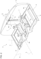
Figure 2 is a rear perspective view of a portion of the work machine according to the invention with parts removed for sake of clarity in a first exemplarily operative condition; -
Figure 3 and4 are a rear perspective view of the portion of work vehicle ofFigure 2 in further exemplarily operative conditions; -
Figures 5 and6 are front perspective views of the portion of the work machine in the operative conditions ofFigures 2 and4 ; -
Figure 7 is a rear enlarged perspective view with sectioned portions of a portion of the work machine according to the invention with parts removed for sake of clarity in a first exemplarily operative condition; and -
Figure 8 is a further rear enlarged perspective view a portion of the work machine according to the invention with parts removed for sake of clarity in a first exemplarily operative condition; - The attached figures disclose a
work vehicle 1, in particular an earthmoving machine, such as a excavator, comprising avehicle body 3 carried by achassis 2 in particular in a movable manner, such as via a rotatingjoint 4, and provided with an operative element such, as a boom. - The
chassis 2 is movable on ground viaground engaging means 5, represented by crawlers in the exemplarily shown embodiment. - The
body 3 essentially comprises a cabin portion 3' configured to define a driving space and a main portion 3'' configured to house the transmission means of the vehicle such as engine, pumps, tanks and any other needed operational system. Thebody 3, as known, carries the operative element. - In detail, the
body 3 extended along a longitudinal axis A direction that coincides, in a standard operation, with the travelling direction of the vehicle and along a transversal axis B direction that is transversal, in particular orthogonal, to longitudinal axis A. - The
body 3 is rotatably carried by rotatingjoint 4 about a vertical axis C that is perpendicular to both longitudinal and transversal axes A, B. - According to the invention (See
figures 1A-1B-1C ), thebody 3, in particular main portion 3'', comprises amovable portion 6 that is carried in a movable manner with respect to the remaining portion ofbody 3 in order to vary its position along at least one direction among the aforementioned longitudinal, transversal or vertical axes A, B, C directions between a closed configuration wherein themovable portion 6 is attached to the remaining portion of thebody 3 and an opened configuration wherein themovable portion 6 is extended with respect to the remaining portion of thebody 3 along the aforementioned at least one direction. - In the exemplarily shown embodiment, the
movable portion 6 is configured so that a bottom portion thereof move along the longitudinal direction axis A to increase the extension of the vehicle along such direction and the top portion of themovable portion 6 is configured to decrease its distance with respect to ground, i.e. along vertical direction axis C. - The
work vehicles 1 further comprises actuator means (as disclosed in the following) and a control unit configured to control the actuator means for carrying themovable portion 6 in a position between the closed and the open configurations. - In particular, the control unit is configured to control the actuator means on the base of signals/data received by sensor means and/or input means of the
work vehicle 1. - In particular, the control unit is an electronic control unit and comprises elaboration means configured to acquire data from sensor means and/or input means of the
work vehicle 1 and estimate a value of the gravity center of the work vehicle. - In case of purely controlled actuation of the actuator means by the driver he can control the input means, such as button or an icon or a display to control the movement of the
movable portion 6. - In case of automatic control system, if the estimated value is above a predetermine safety threshold, then the actuator means are controlled to move the
movable portion 6 in a determine position to allow the gravity center to return under the preset safety threshold. - Such determined position is calculated by the control unit combining the data retrieved by sensor means and by predetermined data of the vehicle such as its weight, the position of the operative elements and dimensions and weight of the movable portions.
- In detail, sensor means may be of any typology configured to allow determination of the gravity center of the vehicle such as inclinometers, weight sensors, pressure sensors, load sensors, displacement or angular sensors etc.
- Making reference to
figures 2 to 6 , it is disclosed into detail an embodiment of themovable portion 6, in particular a rear portion of thebody 3 with respect to longitudinal axis A direction. - The
movable portion 6 movably carried by ahandling system 7 that is operationally interposed between themovable body 6 and aframe 8 of thebody 3 of the vehicle. - In detail, the
frame 8 comprises a base portion that extends on a plane defined by longitudinal and transversal axes A, B. In the disclosed embodiment the base portion comprises a pair ofuprights 8', 8" extending parallel to longitudinal axis A, a pair oftransversal elements transversal element 8a is connected to extremities of the uprights 8', 8'' while a secondtransversal element 8b is connected in an intermediate position thereof distanced along longitudinal axis A with respect to the first. - The base portion in the disclosed embodiment further pair of
longitudinal elements 8c', 8c" parallel to theuprights 8', 8" and laterally comprised therebetween and connected to their extremities to thetransversal elements - The
frame 8 further comprises anelevated portion 8b extending from the base portion along the vertical axis C and in the disclosed embodiment extending from one of thetransversal elements transversal elements 8a. - The
movable portion 6 is carried by the firsttransversal element 8a and the elevatedportion 8b by thehandling system 7 in order to assume the closed configuration wherein it is substantially parallel to the plane defined by the firsttransversal element 8a and the elevatedportion 8b, i.e. by transversal and vertical axes B and C and in the open configuration themovable portion 6 is inclined with respect to such plane such that a top edge thereof gets closer to the ground and a bottom edge thereof tends to get away from the firsttransversal element 8a. - The
handling system 7 comprises in detail an actuation portion 7' and a guidance portion 7''. The actuation portion 7' is configured to provide a pushing or recalling force to the bottom edge of themovable portion 6 thereby moving this latter parallel to longitudinal axis A while the guidance portion 7'' is configured to control the movement of the top edge along a path along vertical axis C. - In particular, the path is inclined with respect to vertical axis C.
- In detail (see
figure 8 ) theguidance portion 7" comprises a pair ofguides 11 each provided with abracket 12 and aslot 14. Thebracket 12 is configured to be connected to themovable portion 6, in particular to the top edge thereof, from one side and to ablock 15 via apin 13 configured to slide withinslot 14. - As show schematically, the
block 15 moves via a prismatic coupling within theslot 14 and is connected fixedly to thepin 13 that is indeed connected to thebracket 12 in a rotatably free manner, e.g. by a bushing. - Therefore the
bracket 12 defined with thepin 13 via a hinge connection while is fixedly connected to the top portion of themovable portion 6 on the other side. - The
slot 14 of each guide is advantageously realized on the lateral walls of theelongated portion 8b for a predetermined length. - The actuation portion 7' essentially comprises at least a
linear actuator 17, for instance a hydraulic cylinder, that is operatively interposed between thebase portion 8 and the bottom edge of themovable portion 6 and configured to extend or retract in order to push out or recall the bottom edge of themovable portion 6 along the longitudinal axis A. - Accordingly the
linear actuator 17 comprises a housing carried rigidly by thebase portion 8 and a rod movably sliding within the housing and whose free terminal portion is coupled via a lever system 22 (described in further detail below) to the bottom edge of themovable portion 6. - The actuation portion 7' further advantageously comprises a pair of sliding
arms 19 slidingly housed within thelongitudinal elements 8c', 8c'' and configured to assist the movement of the bottom edge of themovable portion 6 along the longitudinal axis A. - In the disclosed embodiment two sliding
arms 19 are present, in particular a sliding arm for each of the lateral sides of thecylinder 17 and are connected to their free terminal portions via alever system 22 to the bottom edge of themovable portion 6. - In detail, each
sliding arm 19 comprises asliding block 21, that has preferably a substantially squared cross section in the exemplarily disclosed embodiment, configured to slide within the respectivelongitudinal element 8c', 8c". Thelongitudinal element 8c', 8c' ' is therefore hollow and defines a space suitable for allowing the inside sliding of the slidingblock 21. - The sliding
block 21 can be entirely housed within the space defined by thelongitudinal element 8c', 8c'' in particular thesliding block 21 is housed inside aseat 24 defined by the respectivelongitudinal element 8c', 8c" in the closed position of themovable portion 6 and can be extracted till a maximum extension in the open position of themovable portion 6. - The maximum extension is per se defined by the maximum extension of the
linear actuator 17. - In detail, (see
figure 7 ) each slidingblock 21 is provided with slidingmeans 23 configured facilitate the sliding o theblock 21 within itsseat 24. - In the shown embodiment, sliding means 23 are realized as pads. In particular, one pad can extend from the inner side of the
seat 24 and cooperate by contact with the slidingblock 21 or can be carried by this latter and extends to contact the inner surface of theseat 24. Both embodiments are exemplary shown in the drawings. - With respect to lever system 22 (see
figures 5 ,6 ,7 and8 ) each comprises a pin 22' that is rotatably carried about an axis parallel to transversal axis B by therespective actuator 17/slidingarm 19 and acam portion 22" that is rigidly carried bymovable portion 6 and rotatably supported by the pin 22' in a cantilevered manner. - The operation of the embodiment of the invention as described above is the following making reference to
figures 1A-1B-1C . - When needed, the driver may control via input means the
handling system 7 to control the movement of themovable portion 6 to pass from the closed to the open configuration or an intermediate position thereof. - In case of automatic control system, the control unit acquires the data from sensor means and elaborates the value of center of gravity of the
work vehicle 1. If such value is over a preset safety threshold value, then the control unit controls thehandling system 7 to pass themovable portion 6 from the closed to the open position. - In view of the above, if the control unit is an electronic control unit, the present invention further concerns a method for controlling the center of gravity of a work vehicle comprising the following steps:
- i. Acquiring data from input means and/or sensor means;
- ii. Elaborating the acquired data at step i) via control unit to estimate a gravity center of the work vehicle;
- iii. Evaluate if the estimated value of the gravity center at step ii) is below or above a predetermined safety value;
- iv. If the estimated value is below the predetermined safety value, return to step i), otherwise proceed to step v)
- v. Control the handling system for moving the movable portion in an established position between the closed or open configuration.
- In particular, the established position can be calculated by the control unit by interpolating the estimated value of the gravity center and predetermined data of the work vehicle as listed precedingly.
- For instance, knowing (memorized) the weight of the vehicle, its inclination and the position of the operative element (via sensor means), an equilibrium of torques acting on the work vehicle may be calculated deriving therefore a value of the position of the movable portion that allow to maintain the gravity center below a predetermined threshold.
- In view of the foregoing, the advantages of a work vehicle and related control method according to the invention are apparent.
- Thanks to the proposed system it is possible to vary the gravity center of the work vehicle thereby maintaining this latter below a safety threshold condition in case of need.
- Accordingly, risks of accidents is reduced and consequently safety of the driver is increased.
- Moreover, since the movable portion is itself part of the vehicle body and may vary its position, the body of the work vehicle may be realized lighter, i.e. without known counterweights since the variation of position of the movable portion allows to vary its inertial moment, i.e. lower the gravity center.
- Simulations occurred demonstrate that in the open configuration the work vehicle has a lifting gain of about 6%. Therefore the productivity and the object handling of the work vehicle is increased.
- Moreover, the proposed handling system that allows a roto translation of the movable portion allows in a very compact manner to vary the extension along the extension axis of the work vehicle without lowering the free distance with respect to the ground.
- In this way the gravity center is lowered/inertia is increased without substantially compromising the drivability of the work vehicle.
- It is clear that modifications can be made to the described work vehicle and control method which do not extend beyond the scope of protection defined by the claims.
- For example, the typology, dimension, shape of the work vehicle and the dimension/shape and arrangement of the movable portion may vary.
- Clearly, more movable portion may be present or a movable portion that opens on the transversal side of the vehicle instead on the rear side as disclosed.
- The handling system may be realized differently with respect to the disclosed one and similarly the lever system. Moreover, the lever system may comprise different elements with analogous function with respect to the described one.
Claims (16)
- Work vehicle (1) comprising a body (3) and a chassis (2), said chassis (2) carrying said body (3) and comprising ground engaging means (5) for allowing the motion on ground,wherein said body (3) extends along a longitudinal axis (A), a transversal axis (B) transversal with respect to said longitudinal axis (B) and is carried over said chassis (2) along a vertical axis (C) perpendicular to both said longitudinal and transversal axes (A, B),said body (3) comprising a movable portion (6) carried in a movable manner with respect to the remaining portion of said body (3) in order to vary its position along at least one direction according to one among said axes (A, B, C) between a closed configuration wherein said movable portion (6) is attached to the remaining portion of said body (3) and an opened configuration wherein said movable portion (6) is extended with respect to the remaining portion of said body (3) along said at least one direction.
- Work vehicle according to claim 1, wherein said movable portion (6) is moved so that a bottom portion thereof increases its distance from the remaining portion of said body (3) and so that a top potion thereof decreases its distance with respect to ground.
- Work vehicle according to claim 1 or 2, wherein said body (3) comprises a frame (8) and a handling system (7) operatively interposed between said frame (8) and said movable portion (6) and configured to control the movement of said movable portion (6) between the closed and the opened configurations.
- Work vehicle according to claim 3, wherein said handling system (7) comprises an actuation portion (7') and a guidance portion (7''), said actuation portion (7') being configured to provide a pushing or recalling force to a bottom portion of said movable portion (6) along one between said longitudinal or transversal axes (A, B) while said guidance portion (7") is configured to assist the movement of a top portion of said movable portion (6) along said vertical axis (C) .
- Work vehicle according to claim 4, wherein said guidance portion (7) comprises a bracket (12), a block (15)and a pin (13), the bracket (12) said block (15) being housed in a sliding manner within a slot (14) realized in said frame (3), said bracket (12) being fixedly carried by said top portion of said movable portion (6) from one side and being rotatably free coupler to said pin (13) on the other side.
- Work vehicle according to claim 5, wherein said bracket (12) and said pin (13) define a hinge connection.
- Work vehicle according to any of claims 3 to 6, wherein said actuation portion (7') comprises at least one linear actuator (17).
- Work vehicle according to claim 7, wherein said actuation portion (7') further comprises a pair of sliding arms (19).
- Work vehicle according to claim 7 or 8, wherein said linear actuator (17) comprises a housing fixedly carried by said frame (8) and a rod sliding housed within said housing and connected via a lever system (22) to said bottom portion of said movable portion (6).
- Work vehicle according to any of claims 7 to 9, wherein said sliding arms (19) each comprises a sliding block (21), each sliding block (21) being slidingly housed within said frame (8) and being connected via a lever system (22) to said bottom portion of said movable portion (6).
- Work vehicle according to claim 10, wherein each sliding arm (19) comprises sliding means (23) configured to facilitate the sliding of said sliding arm (19) whtin said frame (8).
- Work vehicle according to claim 9 or 10, wherein said lever system (22) comprises a pin (22') and a cam portion (22''), said pin (22') being rotatably carried from one side by the respective linear actuator (17) or sliding arm (19) along an axis (B) perpendicular to the extension of said linear actuator (17) or sliding arm (19) and carrying from the opposite side said cam portion (22"), said cam portion (22") being fixedly carried by said movable portion (6).
- Work vehicle according to any of claims 3 to 12, further comprising an control unit, input means and sensor means, said control unit being configured to acquire data from said input means and/or sensor means and elaborate the acquired data to control consequently said handling system (7) .
- Work vehicle according to claim 13, wherein said input means comprises a button or an icon on a display.
- Work vehicle according to claim 13 or 14, wherein said sensor means are sensors configured to acquire physical quantities that can be related to the gravity center of said work vehicle.
- Method for controlling the center of gravity of a work vehicle (1) according to any of claims 13 to 15, comprising the following steps:i. Acquiring data from input means and/or sensor means;ii. Elaborating the acquired data at step i) via control unit to estimate a gravity center of the work vehicle;iii. Evaluate if the estimated value of the gravity center at step ii) is below or above a predetermined safety value;iv. If the estimated value is below the predetermined safety value, return to step i), otherwise proceed to step v)v. Control the handling system for moving the movable portion in an established position between the closed or open configuration.
Applications Claiming Priority (1)
| Application Number | Priority Date | Filing Date | Title |
|---|---|---|---|
| IT102023000019017A IT202300019017A1 (en) | 2023-09-15 | 2023-09-15 | IMPROVED WORK VEHICLE AND RELATED CONTROL METHOD |
Publications (1)
| Publication Number | Publication Date |
|---|---|
| EP4524328A1 true EP4524328A1 (en) | 2025-03-19 |
Family
ID=88778806
Family Applications (1)
| Application Number | Title | Priority Date | Filing Date |
|---|---|---|---|
| EP24200375.4A Pending EP4524328A1 (en) | 2023-09-15 | 2024-09-13 | Improved work vehicle and related control method |
Country Status (2)
| Country | Link |
|---|---|
| EP (1) | EP4524328A1 (en) |
| IT (1) | IT202300019017A1 (en) |
Citations (5)
| Publication number | Priority date | Publication date | Assignee | Title |
|---|---|---|---|---|
| US2408500A (en) * | 1944-09-13 | 1946-10-01 | Maxwell A West | Automatic counterbalance for boom derricks |
| DE4409514A1 (en) * | 1993-10-09 | 1995-04-13 | Orenstein & Koppel Ag | Adjustable counterweight for a construction machine, and hydraulic excavator which is equipped with an adjustable counterweight |
| US20090038186A1 (en) * | 2007-08-06 | 2009-02-12 | Extendquip, Llc | Extendable frame work vehicle |
| WO2013105282A1 (en) * | 2012-01-13 | 2013-07-18 | Fukayo Mitsuharu | Construction machine |
| BE1024764A1 (en) * | 2016-11-30 | 2018-06-21 | C M L Ind S A | Construction machine |
-
2023
- 2023-09-15 IT IT102023000019017A patent/IT202300019017A1/en unknown
-
2024
- 2024-09-13 EP EP24200375.4A patent/EP4524328A1/en active Pending
Patent Citations (5)
| Publication number | Priority date | Publication date | Assignee | Title |
|---|---|---|---|---|
| US2408500A (en) * | 1944-09-13 | 1946-10-01 | Maxwell A West | Automatic counterbalance for boom derricks |
| DE4409514A1 (en) * | 1993-10-09 | 1995-04-13 | Orenstein & Koppel Ag | Adjustable counterweight for a construction machine, and hydraulic excavator which is equipped with an adjustable counterweight |
| US20090038186A1 (en) * | 2007-08-06 | 2009-02-12 | Extendquip, Llc | Extendable frame work vehicle |
| WO2013105282A1 (en) * | 2012-01-13 | 2013-07-18 | Fukayo Mitsuharu | Construction machine |
| BE1024764A1 (en) * | 2016-11-30 | 2018-06-21 | C M L Ind S A | Construction machine |
Also Published As
| Publication number | Publication date |
|---|---|
| IT202300019017A1 (en) | 2025-03-15 |
Similar Documents
| Publication | Publication Date | Title |
|---|---|---|
| EP2762642B1 (en) | Skid steer loader lift linkage assembly | |
| EP1559837B1 (en) | Skid steer loader | |
| KR101855970B1 (en) | Construction machinery, and control method for construction machinery | |
| KR101511810B1 (en) | Extendable frame work vehicle | |
| US7963528B2 (en) | Working machine | |
| EP4001514B1 (en) | Work vehicle | |
| CN112513381A (en) | Hydraulic drive device for excavating construction machine | |
| US4734006A (en) | Wheeled building and construction machine of the mechanical shovel, bulldozer or the like type, having articulated steering | |
| EP3199711B1 (en) | Llifting arrangement with self-levelling mechanism for a construction machine | |
| KR101778308B1 (en) | Parallel linkage type operating apparatus for construction heavy equipment | |
| EP0474210B1 (en) | Vertical lift loader boom | |
| US11619026B2 (en) | Motor grader suspended mass ride control | |
| CN110662872A (en) | Loader with lift | |
| EP0671511B1 (en) | Swing type excavator | |
| CN101243229A (en) | Boom Lock Configuration | |
| US4239444A (en) | Power shovel | |
| EP2290163A1 (en) | Construction machine | |
| EP4107047B1 (en) | Joystick anti-hitting seat steering mechanism for work machines | |
| EP1502894B1 (en) | Load handling machine | |
| EP1154081B1 (en) | A machine having a working arm | |
| JP7640963B2 (en) | Construction Machinery | |
| IT202300019017A1 (en) | IMPROVED WORK VEHICLE AND RELATED CONTROL METHOD | |
| GB2368573A (en) | A machine with working arm and having inclined tilt levers | |
| KR102875532B1 (en) | Loader work apparatus comprising self leveling kit | |
| US20250146251A1 (en) | Fine grading system and method for a work machine with a box blade grading attachment |
Legal Events
| Date | Code | Title | Description |
|---|---|---|---|
| PUAI | Public reference made under article 153(3) epc to a published international application that has entered the european phase |
Free format text: ORIGINAL CODE: 0009012 |
|
| STAA | Information on the status of an ep patent application or granted ep patent |
Free format text: STATUS: THE APPLICATION HAS BEEN PUBLISHED |
|
| AK | Designated contracting states |
Kind code of ref document: A1 Designated state(s): AL AT BE BG CH CY CZ DE DK EE ES FI FR GB GR HR HU IE IS IT LI LT LU LV MC ME MK MT NL NO PL PT RO RS SE SI SK SM TR |
|
| STAA | Information on the status of an ep patent application or granted ep patent |
Free format text: STATUS: REQUEST FOR EXAMINATION WAS MADE |
|
| 17P | Request for examination filed |
Effective date: 20250919 |