EP1502894B1 - Load handling machine - Google Patents
Load handling machine Download PDFInfo
- Publication number
- EP1502894B1 EP1502894B1 EP04014729A EP04014729A EP1502894B1 EP 1502894 B1 EP1502894 B1 EP 1502894B1 EP 04014729 A EP04014729 A EP 04014729A EP 04014729 A EP04014729 A EP 04014729A EP 1502894 B1 EP1502894 B1 EP 1502894B1
- Authority
- EP
- European Patent Office
- Prior art keywords
- actuator
- lifting arm
- cylinder
- fluid
- displacement device
- Prior art date
- Legal status (The legal status is an assumption and is not a legal conclusion. Google has not performed a legal analysis and makes no representation as to the accuracy of the status listed.)
- Active
Links
Images

Classifications
-
- B—PERFORMING OPERATIONS; TRANSPORTING
- B66—HOISTING; LIFTING; HAULING
- B66F—HOISTING, LIFTING, HAULING OR PUSHING, NOT OTHERWISE PROVIDED FOR, e.g. DEVICES WHICH APPLY A LIFTING OR PUSHING FORCE DIRECTLY TO THE SURFACE OF A LOAD
- B66F9/00—Devices for lifting or lowering bulky or heavy goods for loading or unloading purposes
- B66F9/06—Devices for lifting or lowering bulky or heavy goods for loading or unloading purposes movable, with their loads, on wheels or the like, e.g. fork-lift trucks
- B66F9/075—Constructional features or details
- B66F9/20—Means for actuating or controlling masts, platforms, or forks
- B66F9/22—Hydraulic devices or systems
-
- B—PERFORMING OPERATIONS; TRANSPORTING
- B66—HOISTING; LIFTING; HAULING
- B66F—HOISTING, LIFTING, HAULING OR PUSHING, NOT OTHERWISE PROVIDED FOR, e.g. DEVICES WHICH APPLY A LIFTING OR PUSHING FORCE DIRECTLY TO THE SURFACE OF A LOAD
- B66F9/00—Devices for lifting or lowering bulky or heavy goods for loading or unloading purposes
- B66F9/06—Devices for lifting or lowering bulky or heavy goods for loading or unloading purposes movable, with their loads, on wheels or the like, e.g. fork-lift trucks
- B66F9/065—Devices for lifting or lowering bulky or heavy goods for loading or unloading purposes movable, with their loads, on wheels or the like, e.g. fork-lift trucks non-masted
- B66F9/0655—Devices for lifting or lowering bulky or heavy goods for loading or unloading purposes movable, with their loads, on wheels or the like, e.g. fork-lift trucks non-masted with a telescopic boom
-
- E—FIXED CONSTRUCTIONS
- E02—HYDRAULIC ENGINEERING; FOUNDATIONS; SOIL SHIFTING
- E02F—DREDGING; SOIL-SHIFTING
- E02F3/00—Dredgers; Soil-shifting machines
- E02F3/04—Dredgers; Soil-shifting machines mechanically-driven
- E02F3/28—Dredgers; Soil-shifting machines mechanically-driven with digging tools mounted on a dipper- or bucket-arm, i.e. there is either one arm or a pair of arms, e.g. dippers, buckets
- E02F3/36—Component parts
- E02F3/42—Drives for dippers, buckets, dipper-arms or bucket-arms
- E02F3/43—Control of dipper or bucket position; Control of sequence of drive operations
- E02F3/431—Control of dipper or bucket position; Control of sequence of drive operations for bucket-arms, front-end loaders, dumpers or the like
- E02F3/432—Control of dipper or bucket position; Control of sequence of drive operations for bucket-arms, front-end loaders, dumpers or the like for keeping the bucket in a predetermined position or attitude
- E02F3/433—Control of dipper or bucket position; Control of sequence of drive operations for bucket-arms, front-end loaders, dumpers or the like for keeping the bucket in a predetermined position or attitude horizontal, e.g. self-levelling
Definitions
- This invention relates to a load handling machine and more particularly to a load handling machine which includes a body, a lifting arm pivotally mounted at or adjacent one end to the body for pivotal movement about a first generally horizontal pivot axis, and the lifting arm carrying at a second end opposite to the first end, a load handling implement, which is mounted for pivotal movement relative to the lifting arm about a second generally horizontal pivot axis.
- a first fluid operated linear actuator is provided which is pivotally mounted at respective first and second ends to the body of the machine at one side of the first pivot axis, and to the lifting arm.
- a second fluid operated linear actuator is provided, typically mounted within the lifting arm, or at least above the second pivot axis, which acts to pivot the load handling implement about the second pivot axis relative to the lifting arm, through a lever, for maximum mechanical advantage.
- a linear displacement device which includes a piston moveable in a cylinder, which is pivotally mounted at respective first and second ends to the body of the machine at the opposite side of the first pivot axis as the first actuator, and to the lifting arm, so that as the lifting arm is raised, fluid is ejected from one side of the piston of the displacement device and is fed to the second actuator which extends, to pivot the load handling implement as the arm is raised, such that the attitude of the load handling implement relative to the ground is maintained.
- the lifting arm is lowered fluid is ejected from the other side of the piston of the displacement device and is fed to the second actuator, so that as the lifting arm lowers, the attitude of the load handling implement relative to the ground, is maintained.
- the second actuator typically is a piston and cylinder type actuator, and a fluid circuit is arranged so that for example, fluid is ejected from a non-annulus side of the displacement device as the arm is raised, and is fed to a non-annulus side of the second actuator as the arm is raised, and conversely, fluid is ejected from the annulus side of the displacement device as the arm is lowered, and is fed to the annulus side of the second actuator.
- a load may be reliably and mechanically maintained at a generally level attitude for example, during raising and lowering of the lifting arm, without operator intervention.
- a disadvantage with such a machine is that the lifting arm must extend beyond the first pivot axis, to provide a pivotal mounting for the displacement device. Moreover, particularly during raising of the lifting arm, fluid which is displaced from the displacement device, will provide a resistance to raising of the arm, which is inefficient.
- the displacement device mounts at the same one side of the first pivot axis as the first actuator. Thus no lifting arm extension beyond the first pivot axis is required.
- the displacement device will act oppositely to that described where the displacement device is at the opposite side of the first pivot axis to the first lifting actuator. That is, as the lifting arm is raised, fluid will be ejected from an annulus side of the displacement device, and as the lifting arm is lowered, fluid will be ejected from the non-annulus side of the displacement device.
- Fluid displaced from the annulus side of the displacement device during arm raising and from the non-annulus side of the displacement device during arm lowering cannot readily be arranged to be fed to the respective non-annulus and annulus sides of the second actuator to maintain the attitude of the load handling implement during both lifting and lowering.
- the second actuator tends to be mounted beneath the lifting arm so as to act between the lifting arm below the second pivot, to pivot the load handling implement.
- a machine in accordance with the invention may realise the advantage of a machine in which the displacement device is mounted on the body of the machine on the same side of the first pivot axis as the first lifting actuator, i.e. the length of the machine can be reduced as there is no requirement for a lifting arm extension beyond the lifting axis, whilst retaining the advantage of having the second actuator being provided above the second pivot axis, e.g. within the lifting arm, and acting to pivot the load handling implement, through a lever which provides maximum mechanical advantage.
- the volume of fluid ejected from the non-annulus side of the cylinder of the second actuator during lowering of the lifting arm is substantially the same as the combined changes in volumes of the annulus sides of the cylinders of the displacement device, and the volume of fluid ejected from annulus side of the cylinder of the second actuator during raising of the lifting arm, is substantially the same as the changing volume of the non-annulus side of the one cylinder of the displacement device.
- fluid pressure which is fed to the first actuator is transmitted to a the non-annulus side of at least one of the cylinders of the displacement device, which thus acts to assist the first actuator in raising the lifting arm.
- fluid from a fluid line to the first actuator may be fed to the non-annulus side of the other of the pair of cylinders of the displacement device, and if desired, a fluid line between the annulus side of the second actuator and the non-annulus side of the one of the pair of cylinders of the displacement device, may pressurised by fluid pressure from the fluid line to the first actuator, e.g. through a check valve, so that the one cylinder of the displacement device too may be pressurised and may assist raising of the arm.
- pressure in the fluid line to the first actuator may be relieved, so that fluid may pass from the non-annulus side of the other of the pair of cylinders of the displacement device, to low pressure.
- the fluid line for pressurised fluid to the first actuator to raise the lifting arm may each include a counterbalance valve, so that that in the event of a loss in pressure, e.g. due to the failure of a fluid line between on the one hand, the respective counterbalance valve and the first actuator, and on the other hand, the respective counterbalance valve and the second actuator, the geometry of the respective actuator will be retained. Thus the risk of a load being suddenly lowered or discharged from the working implement, will be reduced.
- a load handling machine 10 includes a body 11 mounted on a ground engaging structure which in this example includes a front pair of wheels 13 and a rear pair of wheels 14 whereby the machine 10 is moveable over the ground.
- the machine 10 includes an operator's cab 16 from which the machine 10 is controllable, and a lifting arm 18 for raising and lowering of a load on a load handling implement 19.
- the lifting arm 18 is mounted on the body 11 for up and down pivotal movement about a first generally horizontal axis A which in this example is positioned to the rear of the cab 16, but in another example may be in front of the cab 16.
- a first fluid operated linear actuator 20 is provided to raise and permit of lowering of the lifting arm 18, the actuator including a cylinder 21 pivotally mounted on the body 11, and a piston 22 linearly moveable in the cylinder 21, the piston 22 being fast with a piston rod 23 which is pivotally connected to a mounting 24 beneath the lifting arm 18, in front of the pivot axis A, so that as the first actuator 20 is extended, the lifting arm 18 is raised about the axis A, and as the first actuator is retracted, the lifting arm 18 may lower.
- the load handling implement 19 is a pair of lifting forks on a carriage 35, but these could be replaced by a bucket or any other desired load handling implement.
- the load handling implement 19 is pivotally mounted for pivotal movement about a second generally horizontal axis B, to the lifting arm 18, at an end of the lifting arm 18 remote from the first generally horizontal axis A.
- the lifting arm 18 may include a plurality of telescopic sections so that the load may be moved away from and towards the body 11 of the machine 10, in which case, the load handling implement would be provided on the outermost section.
- Pivoting of the load handling implement 19 about the second generally horizontal axis B is achieved by a second fluid operated linear actuator 25 which includes a cylinder 26, a piston 27 linearly moveable in the cylinder 26, and a piston rod 28 fast with the piston 27.
- the cylinder 26 is pivotally mounted inside the lifting arm 18, above the second generally horizontal axis B, and acts to pivot the load handling implement about the second generally horizontal axis B through a lever provided by a linkage mechanism 40.
- the piston rod 28 is pivotally mounted at 32 to a first link 30 of the mechanism 40, which first link 30 acts as a lever which is pivotally mounted to both a second link 31, at 33, and to the lifting arm 18, as indicated at 36 in the drawing, whereby maximum mechanical advantage can be achieved through the mechanism 40 as the second actuator 25 is extended and retracted.
- first link 30 acts as a lever which is pivotally mounted to both a second link 31, at 33, and to the lifting arm 18, as indicated at 36 in the drawing, whereby maximum mechanical advantage can be achieved through the mechanism 40 as the second actuator 25 is extended and retracted.
- the second link 31 extends between the first link 30 and a pivotal mounting 34 on a carriage 35 which carries the forks of the load handling implement 19.
- piston 27 of the second actuator 25 could be directly coupled to the carriage 35, above the second pivot axis B, where the particular geometry allows this.
- Such a linkage mechanism 40 is well known and further detailed description is not considered necessary.
- the linkage mechanism 40 is particularly effective where the load handling implement 19 is a bucket which may be required to dig into a pile of earth or the like, as the maximum mechanical advantage can be realised with the digging bucket at an appropriate angular position about the second generally horizontal axis B, for digging, which is typically where a lower surface of the bucket is generally level with the (level) ground.
- a displacement device 42 which includes a pair of cylinders 44a, 44b, each with respective pistons 45a, 45b linearly moveably mounted inside, each piston 45a, 45b being fast with a respective piston rod 46a, 46b.
- the cylinders 44a, 44b are each pivotally mounted to the body 11 of the machine 10, whilst the piston rods 46a, 46b are each pivotally mounted to the lifting arm 18 at respective pivotal connections 48 at the same side of the first generally horizontal axis A as the first lifting actuator 20.
- the pistons 45a, 45b in each of the cylinders 44a, 44b of the displacement device 42 will move linearly to extend the length of the displacement device 42, and conversely when the lifting arm 18 is permitted to lower, the length of the displacement device 42 will retract.
- a fluid flow control valve 50 is provided by means of which pressurised fluid from a pump may be controlled to be directed along a (lower as shown in the drawing) fluid line 51 to a non-annulus side of the cylinder 21 of the first actuator 20, to extend the actuator 20, thus to raise the lifting arm 18 and at the same time to permit fluid ejected from an annulus side of the cylinder 21 of the first actuator 20 to flow to a low pressure region along a, (upper as shown in the drawing) return, fluid line 52, or alternatively to control pressurised fluid to be directed along the upper line 52 to the annulus side of the cylinder 21 of the first actuator 20 to permit the lifting arm 18 to lower and at the same time to allow fluid ejected from the non-annulus side of the cylinder 21 of the first actuator 20 to pass along the lower fluid line 51 to a low pressure region, e.g. tank 55.
- a low pressure region e.g. tank 55.
- a counterbalance valve 53 In the lower fluid line 51 along which the pressurised fluid passes to the non-annulus side of the cylinder 21 of the first actuator 20 to raise the lifting arm 18, there is provided a counterbalance valve 53, to prevent the sudden lowering of the lifting arm 18 in the event of the failure of either of the fluid lines 51, 52, as is known in the art.
- a (upper as seen in the drawing) fluid line 56 is provided between the annulus side of the piston 27 of the second fluid operated linear actuator 25 and the non-annulus side of the one cylinder 44a (the upper as seen in the drawing) of the pair of cylinders 44a, 44b of the displacement device 42, and a further (lower as seen in the drawing) fluid line 57 is provided between the non-annulus side of the cylinder 26 of the second actuator 25 and both of the annulus sides of the cylinders 44a, 44b of the displacement device 42.
- Another fluid line 58 extends between the non-annulus side of the other cylinder 44b of the pair of cylinders 44a, 44b of the displacement device 42 and the lower fluid line 51 between the control valve 50 and the non-annulus side of the cylinder 21 of the first actuator 20.
- Respective fluid lines 59, 60 extend between the upper fluid line 56 to the annulus side of the cylinder 26 of the second actuator 25, and the flow control valve 50, and between the lower fluid line 57 to the non-annulus side of the cylinder 26 of the second actuator 20 and the flow control valve 50, so that the second actuator 25 may when required, be operated to tilt the loading implement 19 about the second generally horizontal axis B under operator control.
- the fluid system operated as follows.
- the fluid lines 59, 60 from the flow control valve 50 to the second actuator 25 may be closed by the flow control valve 50.
- the piston rods 46a, 46b of the displacement device 42 will be moved outwardly from their respective cylinders 44a, 44b to extend the displacement device 42.
- Fluid at the arm lift pressure in the lower fluid line 51 to the first actuator 20 will be communicated to the non-annulus side of the piston 45b of the lower cylinder 44b of the displacement device 42 to assist raising of the arm 18, and fluid pressure from the lower fluid line 51 to the first actuator 20 will also be communicated, via a check valve 65 to the upper fluid line 56 to the second actuator 25, and hence to the non-annulus side of the upper cylinder 44a, of the displacement device 42 to assist raising of the lifting arm 18.
- Fluid which is ejected from the annulus side of the cylinder 26 of the second actuator 25 will be communicated to the non-annulus side of the piston 45a of the one only (upper) of the cylinders 44a of the displacement device 42, via the second counterbalance valve 62.
- fluid will be ejected from each of the annulus sides of the cylinders 44a, 44b of the displacement device 42 and will pass along the lower fluid line 57 to the non-annulus side of the second actuator 25 thus causing piston 27 of the second actuator 25 to move in its cylinder 26.
- the volume of fluid ejected from the cylinders 44a, 44b of the displacement device 42 is substantially equal to the changing volume of the non-annulus side of the cylinder 26 of the second actuator, so that the load handling implement 19 is caused to pivot about the second generally pivotal axis B by an amount proportional to the changing angle of the lifting arm 18 about the first generally horizontal axis A, so the attitude of the load handling implement 19 relative to the ground, is maintained during arm 18 lifting.
- the volume of fluid ejected from the non-annulus side of the cylinder 26 of the second actuator 25 is again substantially equal to the changing volumes of annulus sides of the cylinder 44a, 44b of the displacement device 42.
- the load handling implement 19 is caused to pivot about the second generally pivotal axis B by an amount proportional to the changing angle of the lifting arm 18 about the first generally horizontal axis A, but oppositely to the pivot direction during lifting arm 18 raising, so the attitude of the load handling implement 19 relative to the ground, is maintained during arm 18 lowering.
- Fluid ejected from the non-annulus side of the lower cylinder 44b of the displacement device 42 passes along the fluid line 58 to the lower fluid line 51 to the first actuator 20, and hence to the low pressure region 55.
- counterbalance valves 53, 62 may be changed depending upon the detailed nature of the hydraulic circuit, and instead of or in addition to the check valve 65 in the line 56 from the lower fluid line to the first actuator 20 and the upper fluid line to the second actuator, another valve to maintain pressure in the fluid line 56 to the second actuator 25 may be provided.
- the flow control valve 50 is preferably a spool valve having separate spools for separately controlling the flow of fluid to the first actuator 20 and the second actuator 25, although other flow control valve arrangements, e.g. separate flow control valves for each actuator 20, 25 may be provided.
- the lifting arm 18 may be raised and lowered whilst the attitude of the load is maintained without operator intervention, and by providing a pair of displacement cylinder 44a, 44b in a circuit as described, these may be positioned at the same side of the first generally horizontal axis A as the first actuator 20, whilst the second actuator 25 may be positioned above the second generally horizontal pivot axis B, within the lifting arm 18 as shown or elsewhere, and my thus act to pivot the load handling implement 19 about the second generally horizontal axis B through the lever provided by the linkage mechanism 40, whilst achieving the best mechanical advantage.
Abstract
Description
- This invention relates to a load handling machine and more particularly to a load handling machine which includes a body, a lifting arm pivotally mounted at or adjacent one end to the body for pivotal movement about a first generally horizontal pivot axis, and the lifting arm carrying at a second end opposite to the first end, a load handling implement, which is mounted for pivotal movement relative to the lifting arm about a second generally horizontal pivot axis.
- In such a machine, for example as disclosed in
FR 2 600 317 - In one typical arrangement, there is a linear displacement device which includes a piston moveable in a cylinder, which is pivotally mounted at respective first and second ends to the body of the machine at the opposite side of the first pivot axis as the first actuator, and to the lifting arm, so that as the lifting arm is raised, fluid is ejected from one side of the piston of the displacement device and is fed to the second actuator which extends, to pivot the load handling implement as the arm is raised, such that the attitude of the load handling implement relative to the ground is maintained. Conversely, as the lifting arm is lowered fluid is ejected from the other side of the piston of the displacement device and is fed to the second actuator, so that as the lifting arm lowers, the attitude of the load handling implement relative to the ground, is maintained.
- The second actuator typically is a piston and cylinder type actuator, and a fluid circuit is arranged so that for example, fluid is ejected from a non-annulus side of the displacement device as the arm is raised, and is fed to a non-annulus side of the second actuator as the arm is raised, and conversely, fluid is ejected from the annulus side of the displacement device as the arm is lowered, and is fed to the annulus side of the second actuator. Thus by matching the sizes of the displacement device and the second actuator, and/or arranging their respective distances from their respective pivots so that the changes in the volumes of fluid in the displacement device and second actuator are substantially the same, a load may be reliably and mechanically maintained at a generally level attitude for example, during raising and lowering of the lifting arm, without operator intervention.
- A disadvantage with such a machine is that the lifting arm must extend beyond the first pivot axis, to provide a pivotal mounting for the displacement device. Moreover, particularly during raising of the lifting arm, fluid which is displaced from the displacement device, will provide a resistance to raising of the arm, which is inefficient.
- It has been proposed to mount the displacement device at the same one side of the first pivot axis as the first actuator. Thus no lifting arm extension beyond the first pivot axis is required. However, the displacement device will act oppositely to that described where the displacement device is at the opposite side of the first pivot axis to the first lifting actuator. That is, as the lifting arm is raised, fluid will be ejected from an annulus side of the displacement device, and as the lifting arm is lowered, fluid will be ejected from the non-annulus side of the displacement device. Fluid displaced from the annulus side of the displacement device during arm raising and from the non-annulus side of the displacement device during arm lowering cannot readily be arranged to be fed to the respective non-annulus and annulus sides of the second actuator to maintain the attitude of the load handling implement during both lifting and lowering.
- Accordingly, in a machine where the displacement device is mounted to the body at the same side that the first actuator is mounted to the body, the second actuator tends to be mounted beneath the lifting arm so as to act between the lifting arm below the second pivot, to pivot the load handling implement. This is disadvantageous in that with such an arrangement, less mechanical advantage can be realised when it is desired to pivot the loading implement about the second pivot axis, for example where the load handling implement is a bucket, and it is desired to pivot the bucket relative to the lifting arm, for example to dig into material to be dug.
- According to a first aspect of the invention we provide a load handling machine according to
claim 1. - A machine in accordance with the invention, may realise the advantage of a machine in which the displacement device is mounted on the body of the machine on the same side of the first pivot axis as the first lifting actuator, i.e. the length of the machine can be reduced as there is no requirement for a lifting arm extension beyond the lifting axis, whilst retaining the advantage of having the second actuator being provided above the second pivot axis, e.g. within the lifting arm, and acting to pivot the load handling implement, through a lever which provides maximum mechanical advantage.
- To realise the invention, preferably the volume of fluid ejected from the non-annulus side of the cylinder of the second actuator during lowering of the lifting arm is substantially the same as the combined changes in volumes of the annulus sides of the cylinders of the displacement device, and the volume of fluid ejected from annulus side of the cylinder of the second actuator during raising of the lifting arm, is substantially the same as the changing volume of the non-annulus side of the one cylinder of the displacement device.
- Desirably, during raising of the lifting arm, fluid pressure which is fed to the first actuator is transmitted to a the non-annulus side of at least one of the cylinders of the displacement device, which thus acts to assist the first actuator in raising the lifting arm. For example, fluid from a fluid line to the first actuator may be fed to the non-annulus side of the other of the pair of cylinders of the displacement device, and if desired, a fluid line between the annulus side of the second actuator and the non-annulus side of the one of the pair of cylinders of the displacement device, may pressurised by fluid pressure from the fluid line to the first actuator, e.g. through a check valve, so that the one cylinder of the displacement device too may be pressurised and may assist raising of the arm.
- During lowering of the lifting arm, pressure in the fluid line to the first actuator may be relieved, so that fluid may pass from the non-annulus side of the other of the pair of cylinders of the displacement device, to low pressure.
- The fluid line for pressurised fluid to the first actuator to raise the lifting arm, and the fluid line between the annulus side of the second actuator and the non-annulus side of the one cylinder of the displacement device, may each include a counterbalance valve, so that that in the event of a loss in pressure, e.g. due to the failure of a fluid line between on the one hand, the respective counterbalance valve and the first actuator, and on the other hand, the respective counterbalance valve and the second actuator, the geometry of the respective actuator will be retained. Thus the risk of a load being suddenly lowered or discharged from the working implement, will be reduced.
- According to a second aspect of the invention we provide a method of lowering a load according to
claim 11. - According to a third aspect of the invention we provide a method of raising a load carried according to claim 12.
- Embodiments of the invention will now be described with reference to the accompanying drawings in which:-
-
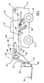
FIGURE 1 is an illustrative side view of a load handling machine in accordance with the invention; -
FIGURE 2 is a more detailed side cross sectional view of part of the lifting arm of the machine offigure 1 ; -
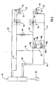
FIGURE 3 is an illustrative hydraulic circuit diagram of the machine offigure 1 . - Referring to the drawings, a
load handling machine 10 includes abody 11 mounted on a ground engaging structure which in this example includes a front pair ofwheels 13 and a rear pair ofwheels 14 whereby themachine 10 is moveable over the ground. Themachine 10 includes an operator'scab 16 from which themachine 10 is controllable, and alifting arm 18 for raising and lowering of a load on a load handling implement 19. - The
lifting arm 18 is mounted on thebody 11 for up and down pivotal movement about a first generally horizontal axis A which in this example is positioned to the rear of thecab 16, but in another example may be in front of thecab 16. - A first fluid operated
linear actuator 20 is provided to raise and permit of lowering of thelifting arm 18, the actuator including acylinder 21 pivotally mounted on thebody 11, and apiston 22 linearly moveable in thecylinder 21, thepiston 22 being fast with apiston rod 23 which is pivotally connected to amounting 24 beneath thelifting arm 18, in front of the pivot axis A, so that as thefirst actuator 20 is extended, thelifting arm 18 is raised about the axis A, and as the first actuator is retracted, thelifting arm 18 may lower. - In this example, the
load handling implement 19 is a pair of lifting forks on acarriage 35, but these could be replaced by a bucket or any other desired load handling implement. - The
load handling implement 19 is pivotally mounted for pivotal movement about a second generally horizontal axis B, to thelifting arm 18, at an end of thelifting arm 18 remote from the first generally horizontal axis A. Thelifting arm 18 may include a plurality of telescopic sections so that the load may be moved away from and towards thebody 11 of themachine 10, in which case, the load handling implement would be provided on the outermost section. - Pivoting of the load handling implement 19 about the second generally horizontal axis B is achieved by a second fluid operated
linear actuator 25 which includes acylinder 26, apiston 27 linearly moveable in thecylinder 26, and apiston rod 28 fast with thepiston 27. Thecylinder 26 is pivotally mounted inside thelifting arm 18, above the second generally horizontal axis B, and acts to pivot the load handling implement about the second generally horizontal axis B through a lever provided by alinkage mechanism 40. - The
piston rod 28 is pivotally mounted at 32 to afirst link 30 of themechanism 40, which firstlink 30 acts as a lever which is pivotally mounted to both asecond link 31, at 33, and to thelifting arm 18, as indicated at 36 in the drawing, whereby maximum mechanical advantage can be achieved through themechanism 40 as thesecond actuator 25 is extended and retracted. Although other linkage arrangements are possible, in this example, thesecond link 31 extends between thefirst link 30 and apivotal mounting 34 on acarriage 35 which carries the forks of the load handling implement 19. - In another example, the
piston 27 of thesecond actuator 25 could be directly coupled to thecarriage 35, above the second pivot axis B, where the particular geometry allows this. - Such a
linkage mechanism 40 is well known and further detailed description is not considered necessary. - The
linkage mechanism 40 is particularly effective where the load handling implement 19 is a bucket which may be required to dig into a pile of earth or the like, as the maximum mechanical advantage can be realised with the digging bucket at an appropriate angular position about the second generally horizontal axis B, for digging, which is typically where a lower surface of the bucket is generally level with the (level) ground. - In accordance with the invention, provided beneath the
lifting arm 18, there is adisplacement device 42 which includes a pair ofcylinders respective pistons piston respective piston rod cylinders body 11 of themachine 10, whilst thepiston rods lifting arm 18 at respective pivotal connections 48 at the same side of the first generally horizontal axis A as thefirst lifting actuator 20. - As the
lifting arm 18 is raised, thepistons cylinders displacement device 42 will move linearly to extend the length of thedisplacement device 42, and conversely when thelifting arm 18 is permitted to lower, the length of thedisplacement device 42 will retract. - Referring now particularly to
figure 3 , a fluidflow control valve 50 is provided by means of which pressurised fluid from a pump may be controlled to be directed along a (lower as shown in the drawing)fluid line 51 to a non-annulus side of thecylinder 21 of thefirst actuator 20, to extend theactuator 20, thus to raise thelifting arm 18 and at the same time to permit fluid ejected from an annulus side of thecylinder 21 of thefirst actuator 20 to flow to a low pressure region along a, (upper as shown in the drawing) return,fluid line 52, or alternatively to control pressurised fluid to be directed along theupper line 52 to the annulus side of thecylinder 21 of thefirst actuator 20 to permit thelifting arm 18 to lower and at the same time to allow fluid ejected from the non-annulus side of thecylinder 21 of thefirst actuator 20 to pass along thelower fluid line 51 to a low pressure region,e.g. tank 55. - In the
lower fluid line 51 along which the pressurised fluid passes to the non-annulus side of thecylinder 21 of thefirst actuator 20 to raise thelifting arm 18, there is provided acounterbalance valve 53, to prevent the sudden lowering of thelifting arm 18 in the event of the failure of either of thefluid lines - A (upper as seen in the drawing)
fluid line 56 is provided between the annulus side of thepiston 27 of the second fluid operatedlinear actuator 25 and the non-annulus side of the onecylinder 44a (the upper as seen in the drawing) of the pair ofcylinders displacement device 42, and a further (lower as seen in the drawing)fluid line 57 is provided between the non-annulus side of thecylinder 26 of thesecond actuator 25 and both of the annulus sides of thecylinders displacement device 42. - Another
fluid line 58 extends between the non-annulus side of theother cylinder 44b of the pair ofcylinders displacement device 42 and thelower fluid line 51 between thecontrol valve 50 and the non-annulus side of thecylinder 21 of thefirst actuator 20. -
Respective fluid lines upper fluid line 56 to the annulus side of thecylinder 26 of thesecond actuator 25, and theflow control valve 50, and between thelower fluid line 57 to the non-annulus side of thecylinder 26 of thesecond actuator 20 and theflow control valve 50, so that thesecond actuator 25 may when required, be operated to tilt the loading implement 19 about the second generally horizontal axis B under operator control. - In the
upper fluid line 56, between thedisplacement device 42 and the annulus side of thecylinder 26 of thesecond actuator 25, there is asecond counterbalance valve 62 for protecting against the sudden discharge of a load being carried, in the event of a failure of either of thefluid lines 59/56 or 60/57. - The fluid system operated as follows.
- During raising of the
lifting arm 18, by extending thefirst actuator 20, thefluid lines flow control valve 50 to thesecond actuator 25 may be closed by theflow control valve 50. As thearm 18 is raised, thepiston rods displacement device 42 will be moved outwardly from theirrespective cylinders displacement device 42. Fluid at the arm lift pressure in thelower fluid line 51 to thefirst actuator 20 will be communicated to the non-annulus side of thepiston 45b of thelower cylinder 44b of thedisplacement device 42 to assist raising of thearm 18, and fluid pressure from thelower fluid line 51 to thefirst actuator 20 will also be communicated, via acheck valve 65 to theupper fluid line 56 to thesecond actuator 25, and hence to the non-annulus side of theupper cylinder 44a, of thedisplacement device 42 to assist raising of thelifting arm 18. - Fluid which is ejected from the annulus side of the
cylinder 26 of thesecond actuator 25 will be communicated to the non-annulus side of thepiston 45a of the one only (upper) of thecylinders 44a of thedisplacement device 42, via thesecond counterbalance valve 62. - At the same time, fluid will be ejected from each of the annulus sides of the
cylinders displacement device 42 and will pass along thelower fluid line 57 to the non-annulus side of thesecond actuator 25 thus causingpiston 27 of thesecond actuator 25 to move in itscylinder 26. The volume of fluid ejected from thecylinders displacement device 42 is substantially equal to the changing volume of the non-annulus side of thecylinder 26 of the second actuator, so that the load handling implement 19 is caused to pivot about the second generally pivotal axis B by an amount proportional to the changing angle of thelifting arm 18 about the first generally horizontal axis A, so the attitude of the load handling implement 19 relative to the ground, is maintained duringarm 18 lifting. - During lowering of the
lifting arm 18, by retracting thefirst actuator 20, and with thefluid lines flow control valve 50 to thesecond actuator 25 still closed by theflow control valve 50, thepiston rods displacement device 42 will be moved inwardly from theirrespective cylinders displacement device 42. Pressurised fluid from theflow control valve 50 will be communicated to the annulus side of thepiston 22 of thefirst actuator 20, and fluid ejected from the non-annulus side of thecylinder 21 of thefirst actuator 20, will pass along thefluid line 51 to thelow pressure region 55. - At the same time fluid ejected from the non-annulus side of
cylinder 26 of thesecond actuator 25 will pass along thelower fluid line 57 to each of the annulus sides of thecylinders displacement device 42 thus causing thepistons displacement device 42, to move in their cylinders. - The volume of fluid ejected from the non-annulus side of the
cylinder 26 of thesecond actuator 25 is again substantially equal to the changing volumes of annulus sides of thecylinder displacement device 42. Thus the load handling implement 19 is caused to pivot about the second generally pivotal axis B by an amount proportional to the changing angle of the liftingarm 18 about the first generally horizontal axis A, but oppositely to the pivot direction during liftingarm 18 raising, so the attitude of the load handling implement 19 relative to the ground, is maintained duringarm 18 lowering. - Fluid ejected from the non-annulus side of the
lower cylinder 44b of thedisplacement device 42 passes along thefluid line 58 to thelower fluid line 51 to thefirst actuator 20, and hence to thelow pressure region 55. - Various modifications may be made without departing from the scope of the invention. For example, the location and type of
counterbalance valves check valve 65 in theline 56 from the lower fluid line to thefirst actuator 20 and the upper fluid line to the second actuator, another valve to maintain pressure in thefluid line 56 to thesecond actuator 25 may be provided. - The
flow control valve 50 is preferably a spool valve having separate spools for separately controlling the flow of fluid to thefirst actuator 20 and thesecond actuator 25, although other flow control valve arrangements, e.g. separate flow control valves for each actuator 20, 25 may be provided. - In accordance with the invention, by closing the flow
control fluid lines flow control valve 50 and thesecond actuator 25, the liftingarm 18 may be raised and lowered whilst the attitude of the load is maintained without operator intervention, and by providing a pair ofdisplacement cylinder first actuator 20, whilst thesecond actuator 25 may be positioned above the second generally horizontal pivot axis B, within the liftingarm 18 as shown or elsewhere, and my thus act to pivot the load handling implement 19 about the second generally horizontal axis B through the lever provided by thelinkage mechanism 40, whilst achieving the best mechanical advantage.
Claims (12)
- A load handling machine (10) including a body (11), a lifting arm (18) pivotally mounted at or closely adjacent one end to the body (11) for pivotal movement about a first generally horizontal pivot axis (A); and the lifting arm (18) carrying at a second end opposite to the first end, a load handling implement (19), which is mounted for pivotal movement relative to the lifting arm (18) about a second generally horizontal pivot axis (B), a first fluid operated linear actuator (20) pivotally mounted at respective first and second ends to the body (11) of the machine (20) at one side of the first pivot axis (A), and to the lifting arm (18), for raising and permitting of lowering the lifting arm (18) about the first pivot axis (A), and a second fluid operated linear actuator (25) for pivoting the load handling implement (19) about the second pivot axis (B), the second actuator (25) including a piston (27) linearly moveable in a cylinder (26), the cylinder (26) thus having an annulus side and a non-annulus side and wherein the second actuator (25) is mounted above the second pivot axis (B) and is operable to pivot the load handling implement (19) through a lever (30, 31), and characterised by there being a linear displacement device (42) which includes a pair of cylinders (44a, 44b) each having linearly moveable therein, a respective piston (45a, 45b), each cylinder (44a, 44b) thus having an annulus side and a non-annulus side, and each cylinder (44a, 44b) being pivotally mounted at respective first and second ends to the body (11) of the machine (10) at the same one side of the first pivot axis (A) as the first actuator (20), and to the lifting arm (18), the second actuator (25) and the displacement device (42) being interconnected so that as the lifting arm (18) is lowered, fluid is ejected from a non-annulus side of one of the pair of cylinders (44a, 44b) of the displacement device (42) and is fed to an annulus side of the second actuator (25), and as the lifting arm (18) is raised, fluid is ejected from the annulus sides of both of the cylinders (44a, 44b) of the displacement device (42) and is fed to the non-annulus side of the cylinder (26) of the second actuator (25) thus to maintain the attitude of the load handling implement (19) relative to the ground, during lowering and raising of the lifting arm (18).
- A machine according to claim 1 characterised in that the second actuator (25) is pivotally mounted within the lifting arm (18), and acts to pivot the load handling implement (19), through a lever (30, 31).
- A machine according to claim 1 or claim 2 characterised in that the volume of fluid ejected from the non-annulus side of the cylinder (26) of the second actuator (25) during lowering of the lifting arm (18) is substantially the same as the combined changes in volumes of the annulus sides of the cylinders (44a, 44b) of the displacement device (42), and the volume of fluid ejected from annulus side of the cylinder (26) of the second actuator (25) during raising of the lifting arm (18), is substantially the same as the changing volume of the non-annulus side of the one cylinder (44a, 44b) of the displacement device (42).
- A machine according to any one of the preceding claims characterised in that during raising of the lifting arm (18), fluid pressure which is fed to the first actuator (20) is transmitted to a the non-annulus side of at least one of the cylinders (44a, 44b) of the displacement device (42), which thus acts to assist the first actuator (20) in raising the lifting arm (18).
- A machine according to claim 4 characterised in that during raising of the lifting arm (18), fluid from a fluid line (51) to the first actuator (20) is fed to the non-annulus side of the other of the pair of cylinders (44b) of the displacement device (42).
- A machine according to claim 4 or claim 5 characterised in that a fluid line (57) between the annulus side of the second actuator (25) and the non-annulus side of the one of the pair of cylinders (44a) of the displacement device (42), is pressurised by fluid pressure from the fluid line (51) to the first actuator (20) so that the one cylinder (44a) of the displacement device (42) too may assist raising of the arm (18).
- A machine according to claim 6 characterised in that the fluid line (56) between the annulus side of the second actuator (25) and the non-annulus side of the one of the pair of cylinders (44a) of the displacement device (42), is pressurised through a check valve (65).
- A machine according to any one of claims 5 to 7 where dependant upon claim 5 characterised in that during lowering of the lifting arm (18), pressure in the fluid line to the first actuator (20) is relieved, so that fluid may pass from the non-annulus side of the other (44b) of the pair of cylinders of the displacement device (42), to low pressure (55).
- A machine according to any one of the preceding claims characterised in that the fluid line (51) for pressurised fluid to the first actuator (20) to raise the lifting arm includes a counterbalance valve (53).
- A machine according to any one of the preceding claims characterised in that the fluid line (56) between the annulus side of the second actuator (25) and the non-annulus side of the one cylinder (44a) of the displacement device (42), includes a counterbalance valve (62).
- A method of lowering a load carried on a lifting arm (18) of a load handling machine (10) of the kind in which the lifting arm (18) is pivotally mounted at or closely adjacent one end to a body (11) of the machine (10) for pivotal movement about a first generally horizontal pivot axis (A), and the lifting arm (18) carrying at a second end opposite to the first end, a load handling implement (19), which is mounted for pivotal movement relative to the lifting arm (18) about a second generally horizontal pivot axis (B), a first fluid operated linear actuator (20) pivotally mounted at respective first and second ends to the body (11) of the machine (10) at one side of the first pivot axis (A), and to the lifting arm (18), for raising and permitting of lowering the lifting arm (18) about the first pivot axis (A), and a second fluid operated linear actuator (25) for pivoting the load handling implement (19) about the second pivot axis (B), the second actuator (25) including a piston (27) linearly moveable in a cylinder (26), the cylinder (26) thus having an annulus side and a non-annulus side, and wherein the second actuator (25) is mounted above the second pivot axis (B) and is operable to pivot the load handling implement (19) through a lever (30, 31), and characterised by there being a linear displacement device (42) which includes a pair of cylinders (44a, 44b) each having linearly moveable therein, a respective piston (45a, 45b), each cylinder (44a, 44b) thus having an annulus side and a non-anriulus side, and each cylinder (44a, 44b) being pivotally mounted at respective first and second ends to the body (11) of the machine (10) at the same one side of the first pivot axis (A) as the first actuator (20), and to the lifting arm (18), the method including during lowering of the lifting arm (18), feeding fluid ejected from a non-annulus side of one (44a) of the pair of cylinders of the displacement device (42) to an annulus side of the second actuator (25), thus to maintain the attitude of the load handling implement (19) relative to the ground, during lowering of the lifting arm (18).
- A method of raising a load carried on a lifting arm (18) of a load handling machine (10) of the kind in which the lifting arm (18) is pivotally mounted at or closely adjacent one end to a body (11) of the machine (10) for pivotal movement about a first generally horizontal pivot axis (A), and the lifting arm (18) carrying at a second end opposite to the first end, a load handling implement (19), which is mounted for pivotal movement relative to the lifting arm (18) about a second generally horizontal pivot axis (B), a first fluid operated linear actuator (20) pivotally mounted at respective first and second ends to the body (11) of the machine (10) at one side of the first pivot axis (A), and to the lifting arm (18), for raising and permitting of lowering the lifting arm (18) about the first pivot axis (A), and a second fluid operated linear actuator (25) for pivoting the load handling implement (19) about the second pivot axis (B), the second actuator (25) including a piston (27) linearly moveable in a cylinder (26), the cylinder (26) thus having an annulus side and a non-annulus side, and wherein the second actuator (25) is mounted above the second pivot axis (B) and is operable to pivot the load handling implement (19) through a lever (30, 31), and characterised by there being a linear displacement device (42) which includes a pair of cylinders (44a, 44b) each having linearly moveable therein, a respective piston (45a, 45b), each cylinder (44a, 44b) thus having an annulus side and a non-annulus side, and each cylinder (44a, 44b) being pivotally mounted at respective first and second ends to the body (11) of the machine (10) at the same one side of the first pivot axis (A) as the first actuator (20), and to the lifting arm (18), the method including during raising of the lifting arm (18), feeding fluid ejected from the annulus sides of both of the cylinders (44a, 44b) of the displacement device (42) to the non-annulus side of the cylinder (26) of the second actuator (35) thus to maintain the attitude of the load handling implement (19) relative to the ground, during raising of the lifting arm (18).
Applications Claiming Priority (2)
| Application Number | Priority Date | Filing Date | Title |
|---|---|---|---|
| GB0317777A GB2404365B (en) | 2003-07-30 | 2003-07-30 | Load handling machine |
| GB0317777 | 2003-07-30 |
Publications (3)
| Publication Number | Publication Date |
|---|---|
| EP1502894A2 EP1502894A2 (en) | 2005-02-02 |
| EP1502894A3 EP1502894A3 (en) | 2005-11-02 |
| EP1502894B1 true EP1502894B1 (en) | 2011-03-16 |
Family
ID=27799431
Family Applications (1)
| Application Number | Title | Priority Date | Filing Date |
|---|---|---|---|
| EP04014729A Active EP1502894B1 (en) | 2003-07-30 | 2004-06-23 | Load handling machine |
Country Status (6)
| Country | Link |
|---|---|
| US (1) | US7044705B2 (en) |
| EP (1) | EP1502894B1 (en) |
| AT (1) | ATE501972T1 (en) |
| DE (1) | DE602004031803D1 (en) |
| ES (1) | ES2363084T3 (en) |
| GB (1) | GB2404365B (en) |
Families Citing this family (6)
| Publication number | Priority date | Publication date | Assignee | Title |
|---|---|---|---|---|
| US7207396B2 (en) | 2002-12-10 | 2007-04-24 | Intelliserv, Inc. | Method and apparatus of assessing down-hole drilling conditions |
| CA170432S (en) * | 2016-04-06 | 2017-11-23 | Manitou Bf | FORKLIFT |
| CN113474512B (en) | 2019-02-22 | 2023-06-02 | 克拉克设备公司 | Hydraulic leveling circuit for power machine |
| US20220227610A1 (en) * | 2019-06-07 | 2022-07-21 | Manitou Bf | Load handling machine and method for controlling a load handling machine |
| US10676893B1 (en) * | 2019-09-10 | 2020-06-09 | Larry Irby Williams | Self-leveling front-end loader having a double boom with a dogleg bend of 105 to 135 degrees including an extension powered by hydraulic cylinders |
| FR3135260B1 (en) * | 2022-05-03 | 2024-03-29 | Manitou Bf | Handling machine with lifting arm comprising a device for blocking the rotation of the lifting arm |
Family Cites Families (9)
| Publication number | Priority date | Publication date | Assignee | Title |
|---|---|---|---|---|
| SU450779A1 (en) * | 1971-03-17 | 1974-11-25 | Проектно-Конструкторское Бюро По Механизации Энергетического Строительства | Tracking mechanism for telescopic booms |
| US3862697A (en) * | 1972-08-24 | 1975-01-28 | Caterpillar Tractor Co | Front loading hydraulic excavator |
| US3836025A (en) * | 1973-05-21 | 1974-09-17 | Loed Corp | Material-handling machine |
| FR2415600A1 (en) * | 1978-01-30 | 1979-08-24 | Baas Technik Gmbh | PARALLEL GUIDANCE DEVICE FOR A VEHICLE-MOUNTED FRONT LOADING EQUIPMENT |
| US4266909A (en) * | 1979-01-29 | 1981-05-12 | Westendorf Manufacturing Co. | Means for hydraulic self-leveling of a loader bucket |
| US4822237A (en) * | 1985-11-21 | 1989-04-18 | The Gradall Company | Extended reach materials handling apparatus |
| FR2600317B1 (en) * | 1986-06-23 | 1988-10-21 | Agram | LOADER WITH HYDRAULIC CORRECTION ADAPTABLE TO SELF-PROPELLED CARRIER |
| FR2731729B1 (en) * | 1995-03-16 | 1997-06-06 | Soc Et Et D Innovation Dans Le | HYDRAULIC CONTROL SYSTEM FOR LOADER |
| GB2327076A (en) * | 1997-07-08 | 1999-01-13 | Bamford Excavators Ltd | Hydraulic crowd mechanisms |
-
2003
- 2003-07-30 GB GB0317777A patent/GB2404365B/en not_active Expired - Lifetime
-
2004
- 2004-06-23 AT AT04014729T patent/ATE501972T1/en active
- 2004-06-23 ES ES04014729T patent/ES2363084T3/en active Active
- 2004-06-23 EP EP04014729A patent/EP1502894B1/en active Active
- 2004-06-23 DE DE602004031803T patent/DE602004031803D1/en active Active
- 2004-06-29 US US10/879,944 patent/US7044705B2/en active Active
Also Published As
| Publication number | Publication date |
|---|---|
| GB2404365A (en) | 2005-02-02 |
| ES2363084T3 (en) | 2011-07-20 |
| US20050036874A1 (en) | 2005-02-17 |
| ATE501972T1 (en) | 2011-04-15 |
| EP1502894A2 (en) | 2005-02-02 |
| US7044705B2 (en) | 2006-05-16 |
| GB0317777D0 (en) | 2003-09-03 |
| DE602004031803D1 (en) | 2011-04-28 |
| EP1502894A3 (en) | 2005-11-02 |
| GB2404365B (en) | 2006-03-15 |
Similar Documents
| Publication | Publication Date | Title |
|---|---|---|
| EP1961694B1 (en) | Wheeled loader having a loader arm assembly. | |
| EP1375926B1 (en) | Hydraulic control system for a working machine | |
| EP1619161A1 (en) | Method of and machine with device for limiting boom radius | |
| AU743652B2 (en) | System for frame leveling and stabilizing a forklift | |
| EP1764339B1 (en) | Hydraulic arrangement for a lifting arm pivotably mounted on a vehicle | |
| JP3119722B2 (en) | Hydraulic circuit of 4-position closed center switching valve by pressure proportional control valve | |
| EP2350399B1 (en) | Flow compensated restrictive orifice for overrunning load protection | |
| CA2523660A1 (en) | Folding lift arm assembly for skid steer loader | |
| US4324525A (en) | Loading apparatus | |
| EP1502894B1 (en) | Load handling machine | |
| EP1531141B1 (en) | Piggyback forklift truck | |
| US5201235A (en) | Linkage for loader bucket or other material handling device | |
| EP0474210B1 (en) | Vertical lift loader boom | |
| CN213270501U (en) | Automatic tilt control system | |
| US5678979A (en) | Tilt linkage system for load elevating vehicles | |
| US20220213664A1 (en) | Variable system pressure based on implement position | |
| US20210025129A1 (en) | Valve configuration for front end loaders | |
| US11654815B2 (en) | Closed center hoist valve with snubbing | |
| KR102297031B1 (en) | Angle control apparatus of link for tractor | |
| US11661723B1 (en) | Variable system pressure based on implement position | |
| CN116607458A (en) | Two-stage lifting system for snow wings | |
| JPH0749664B2 (en) | Hydraulic drive circuit for attachment translation operation of loader for agricultural machinery tractor |
Legal Events
| Date | Code | Title | Description |
|---|---|---|---|
| PUAI | Public reference made under article 153(3) epc to a published international application that has entered the european phase |
Free format text: ORIGINAL CODE: 0009012 |
|
| AK | Designated contracting states |
Kind code of ref document: A2 Designated state(s): AT BE BG CH CY CZ DE DK EE ES FI FR GB GR HU IE IT LI LU MC NL PL PT RO SE SI SK TR |
|
| AX | Request for extension of the european patent |
Extension state: AL HR LT LV MK |
|
| PUAL | Search report despatched |
Free format text: ORIGINAL CODE: 0009013 |
|
| AK | Designated contracting states |
Kind code of ref document: A3 Designated state(s): AT BE BG CH CY CZ DE DK EE ES FI FR GB GR HU IE IT LI LU MC NL PL PT RO SE SI SK TR |
|
| AX | Request for extension of the european patent |
Extension state: AL HR LT LV MK |
|
| 17P | Request for examination filed |
Effective date: 20060411 |
|
| AKX | Designation fees paid |
Designated state(s): AT BE BG CH CY CZ DE DK EE ES FI FR GB GR HU IE IT LI LU MC NL PL PT RO SE SI SK TR |
|
| GRAP | Despatch of communication of intention to grant a patent |
Free format text: ORIGINAL CODE: EPIDOSNIGR1 |
|
| GRAS | Grant fee paid |
Free format text: ORIGINAL CODE: EPIDOSNIGR3 |
|
| GRAA | (expected) grant |
Free format text: ORIGINAL CODE: 0009210 |
|
| AK | Designated contracting states |
Kind code of ref document: B1 Designated state(s): AT BE BG CH CY CZ DE DK EE ES FI FR GB GR HU IE IT LI LU MC NL PL PT RO SE SI SK TR |
|
| REG | Reference to a national code |
Ref country code: GB Ref legal event code: FG4D |
|
| REG | Reference to a national code |
Ref country code: CH Ref legal event code: EP |
|
| REG | Reference to a national code |
Ref country code: IE Ref legal event code: FG4D |
|
| REF | Corresponds to: |
Ref document number: 602004031803 Country of ref document: DE Date of ref document: 20110428 Kind code of ref document: P |
|
| REG | Reference to a national code |
Ref country code: DE Ref legal event code: R096 Ref document number: 602004031803 Country of ref document: DE Effective date: 20110428 |
|
| REG | Reference to a national code |
Ref country code: NL Ref legal event code: T3 |
|
| REG | Reference to a national code |
Ref country code: ES Ref legal event code: FG2A Ref document number: 2363084 Country of ref document: ES Kind code of ref document: T3 Effective date: 20110720 |
|
| PG25 | Lapsed in a contracting state [announced via postgrant information from national office to epo] |
Ref country code: SE Free format text: LAPSE BECAUSE OF FAILURE TO SUBMIT A TRANSLATION OF THE DESCRIPTION OR TO PAY THE FEE WITHIN THE PRESCRIBED TIME-LIMIT Effective date: 20110316 Ref country code: GR Free format text: LAPSE BECAUSE OF FAILURE TO SUBMIT A TRANSLATION OF THE DESCRIPTION OR TO PAY THE FEE WITHIN THE PRESCRIBED TIME-LIMIT Effective date: 20110617 |
|
| PGFP | Annual fee paid to national office [announced via postgrant information from national office to epo] |
Ref country code: MC Payment date: 20110530 Year of fee payment: 8 Ref country code: LU Payment date: 20110621 Year of fee payment: 8 Ref country code: IE Payment date: 20110610 Year of fee payment: 8 Ref country code: CH Payment date: 20110614 Year of fee payment: 8 |
|
| PG25 | Lapsed in a contracting state [announced via postgrant information from national office to epo] |
Ref country code: SI Free format text: LAPSE BECAUSE OF FAILURE TO SUBMIT A TRANSLATION OF THE DESCRIPTION OR TO PAY THE FEE WITHIN THE PRESCRIBED TIME-LIMIT Effective date: 20110316 Ref country code: FI Free format text: LAPSE BECAUSE OF FAILURE TO SUBMIT A TRANSLATION OF THE DESCRIPTION OR TO PAY THE FEE WITHIN THE PRESCRIBED TIME-LIMIT Effective date: 20110316 Ref country code: CY Free format text: LAPSE BECAUSE OF FAILURE TO SUBMIT A TRANSLATION OF THE DESCRIPTION OR TO PAY THE FEE WITHIN THE PRESCRIBED TIME-LIMIT Effective date: 20110316 Ref country code: BG Free format text: LAPSE BECAUSE OF FAILURE TO SUBMIT A TRANSLATION OF THE DESCRIPTION OR TO PAY THE FEE WITHIN THE PRESCRIBED TIME-LIMIT Effective date: 20110616 |
|
| PGFP | Annual fee paid to national office [announced via postgrant information from national office to epo] |
Ref country code: DK Payment date: 20110610 Year of fee payment: 8 Ref country code: AT Payment date: 20110526 Year of fee payment: 8 Ref country code: NL Payment date: 20110621 Year of fee payment: 8 |
|
| PGFP | Annual fee paid to national office [announced via postgrant information from national office to epo] |
Ref country code: BE Payment date: 20110614 Year of fee payment: 8 |
|
| PG25 | Lapsed in a contracting state [announced via postgrant information from national office to epo] |
Ref country code: PT Free format text: LAPSE BECAUSE OF FAILURE TO SUBMIT A TRANSLATION OF THE DESCRIPTION OR TO PAY THE FEE WITHIN THE PRESCRIBED TIME-LIMIT Effective date: 20110718 Ref country code: EE Free format text: LAPSE BECAUSE OF FAILURE TO SUBMIT A TRANSLATION OF THE DESCRIPTION OR TO PAY THE FEE WITHIN THE PRESCRIBED TIME-LIMIT Effective date: 20110316 |
|
| PG25 | Lapsed in a contracting state [announced via postgrant information from national office to epo] |
Ref country code: CZ Free format text: LAPSE BECAUSE OF FAILURE TO SUBMIT A TRANSLATION OF THE DESCRIPTION OR TO PAY THE FEE WITHIN THE PRESCRIBED TIME-LIMIT Effective date: 20110316 Ref country code: RO Free format text: LAPSE BECAUSE OF FAILURE TO SUBMIT A TRANSLATION OF THE DESCRIPTION OR TO PAY THE FEE WITHIN THE PRESCRIBED TIME-LIMIT Effective date: 20110316 Ref country code: SK Free format text: LAPSE BECAUSE OF FAILURE TO SUBMIT A TRANSLATION OF THE DESCRIPTION OR TO PAY THE FEE WITHIN THE PRESCRIBED TIME-LIMIT Effective date: 20110316 |
|
| PGFP | Annual fee paid to national office [announced via postgrant information from national office to epo] |
Ref country code: ES Payment date: 20110715 Year of fee payment: 8 |
|
| PLBE | No opposition filed within time limit |
Free format text: ORIGINAL CODE: 0009261 |
|
| STAA | Information on the status of an ep patent application or granted ep patent |
Free format text: STATUS: NO OPPOSITION FILED WITHIN TIME LIMIT |
|
| PG25 | Lapsed in a contracting state [announced via postgrant information from national office to epo] |
Ref country code: DK Free format text: LAPSE BECAUSE OF NON-PAYMENT OF DUE FEES Effective date: 20110316 |
|
| 26N | No opposition filed |
Effective date: 20111219 |
|
| PG25 | Lapsed in a contracting state [announced via postgrant information from national office to epo] |
Ref country code: PL Free format text: LAPSE BECAUSE OF FAILURE TO SUBMIT A TRANSLATION OF THE DESCRIPTION OR TO PAY THE FEE WITHIN THE PRESCRIBED TIME-LIMIT Effective date: 20110316 |
|
| REG | Reference to a national code |
Ref country code: DE Ref legal event code: R097 Ref document number: 602004031803 Country of ref document: DE Effective date: 20111219 |
|
| BERE | Be: lapsed |
Owner name: J.C. BAMFORD EXCAVATORS LTD Effective date: 20120630 |
|
| REG | Reference to a national code |
Ref country code: NL Ref legal event code: V1 Effective date: 20130101 |
|
| PG25 | Lapsed in a contracting state [announced via postgrant information from national office to epo] |
Ref country code: MC Free format text: LAPSE BECAUSE OF NON-PAYMENT OF DUE FEES Effective date: 20120630 |
|
| REG | Reference to a national code |
Ref country code: CH Ref legal event code: PL |
|
| REG | Reference to a national code |
Ref country code: AT Ref legal event code: MM01 Ref document number: 501972 Country of ref document: AT Kind code of ref document: T Effective date: 20120623 Ref country code: CH Ref legal event code: PL |
|
| REG | Reference to a national code |
Ref country code: IE Ref legal event code: MM4A |
|
| PG25 | Lapsed in a contracting state [announced via postgrant information from national office to epo] |
Ref country code: LI Free format text: LAPSE BECAUSE OF NON-PAYMENT OF DUE FEES Effective date: 20120630 Ref country code: BE Free format text: LAPSE BECAUSE OF NON-PAYMENT OF DUE FEES Effective date: 20120630 Ref country code: NL Free format text: LAPSE BECAUSE OF NON-PAYMENT OF DUE FEES Effective date: 20130101 Ref country code: CH Free format text: LAPSE BECAUSE OF NON-PAYMENT OF DUE FEES Effective date: 20120630 Ref country code: IE Free format text: LAPSE BECAUSE OF NON-PAYMENT OF DUE FEES Effective date: 20120623 |
|
| PG25 | Lapsed in a contracting state [announced via postgrant information from national office to epo] |
Ref country code: AT Free format text: LAPSE BECAUSE OF NON-PAYMENT OF DUE FEES Effective date: 20120623 |
|
| PG25 | Lapsed in a contracting state [announced via postgrant information from national office to epo] |
Ref country code: TR Free format text: LAPSE BECAUSE OF FAILURE TO SUBMIT A TRANSLATION OF THE DESCRIPTION OR TO PAY THE FEE WITHIN THE PRESCRIBED TIME-LIMIT Effective date: 20110316 |
|
| REG | Reference to a national code |
Ref country code: ES Ref legal event code: FD2A Effective date: 20131018 |
|
| PG25 | Lapsed in a contracting state [announced via postgrant information from national office to epo] |
Ref country code: HU Free format text: LAPSE BECAUSE OF FAILURE TO SUBMIT A TRANSLATION OF THE DESCRIPTION OR TO PAY THE FEE WITHIN THE PRESCRIBED TIME-LIMIT Effective date: 20110316 Ref country code: ES Free format text: LAPSE BECAUSE OF NON-PAYMENT OF DUE FEES Effective date: 20120624 |
|
| PG25 | Lapsed in a contracting state [announced via postgrant information from national office to epo] |
Ref country code: LU Free format text: LAPSE BECAUSE OF NON-PAYMENT OF DUE FEES Effective date: 20120623 |
|
| REG | Reference to a national code |
Ref country code: FR Ref legal event code: PLFP Year of fee payment: 13 |
|
| REG | Reference to a national code |
Ref country code: FR Ref legal event code: PLFP Year of fee payment: 14 |
|
| REG | Reference to a national code |
Ref country code: FR Ref legal event code: PLFP Year of fee payment: 15 |
|
| PGFP | Annual fee paid to national office [announced via postgrant information from national office to epo] |
Ref country code: FR Payment date: 20230629 Year of fee payment: 20 Ref country code: DE Payment date: 20230629 Year of fee payment: 20 |
|
| PGFP | Annual fee paid to national office [announced via postgrant information from national office to epo] |
Ref country code: IT Payment date: 20230628 Year of fee payment: 20 Ref country code: GB Payment date: 20230608 Year of fee payment: 20 |