EP4524085A2 - Viewing windows in a materials handling vehicle - Google Patents
Viewing windows in a materials handling vehicle Download PDFInfo
- Publication number
- EP4524085A2 EP4524085A2 EP24222627.2A EP24222627A EP4524085A2 EP 4524085 A2 EP4524085 A2 EP 4524085A2 EP 24222627 A EP24222627 A EP 24222627A EP 4524085 A2 EP4524085 A2 EP 4524085A2
- Authority
- EP
- European Patent Office
- Prior art keywords
- assembly
- operator
- operator control
- viewing window
- vehicle
- Prior art date
- Legal status (The legal status is an assumption and is not a legal conclusion. Google has not performed a legal analysis and makes no representation as to the accuracy of the status listed.)
- Pending
Links
Images




















Classifications
-
- B—PERFORMING OPERATIONS; TRANSPORTING
- B66—HOISTING; LIFTING; HAULING
- B66F—HOISTING, LIFTING, HAULING OR PUSHING, NOT OTHERWISE PROVIDED FOR, e.g. DEVICES WHICH APPLY A LIFTING OR PUSHING FORCE DIRECTLY TO THE SURFACE OF A LOAD
- B66F9/00—Devices for lifting or lowering bulky or heavy goods for loading or unloading purposes
- B66F9/06—Devices for lifting or lowering bulky or heavy goods for loading or unloading purposes movable, with their loads, on wheels or the like, e.g. fork-lift trucks
- B66F9/075—Constructional features or details
- B66F9/0759—Details of operating station, e.g. seats, levers, operator platforms, cabin suspension
-
- B—PERFORMING OPERATIONS; TRANSPORTING
- B66—HOISTING; LIFTING; HAULING
- B66F—HOISTING, LIFTING, HAULING OR PUSHING, NOT OTHERWISE PROVIDED FOR, e.g. DEVICES WHICH APPLY A LIFTING OR PUSHING FORCE DIRECTLY TO THE SURFACE OF A LOAD
- B66F9/00—Devices for lifting or lowering bulky or heavy goods for loading or unloading purposes
- B66F9/06—Devices for lifting or lowering bulky or heavy goods for loading or unloading purposes movable, with their loads, on wheels or the like, e.g. fork-lift trucks
- B66F9/075—Constructional features or details
- B66F9/07545—Overhead guards
-
- B—PERFORMING OPERATIONS; TRANSPORTING
- B66—HOISTING; LIFTING; HAULING
- B66F—HOISTING, LIFTING, HAULING OR PUSHING, NOT OTHERWISE PROVIDED FOR, e.g. DEVICES WHICH APPLY A LIFTING OR PUSHING FORCE DIRECTLY TO THE SURFACE OF A LOAD
- B66F9/00—Devices for lifting or lowering bulky or heavy goods for loading or unloading purposes
- B66F9/06—Devices for lifting or lowering bulky or heavy goods for loading or unloading purposes movable, with their loads, on wheels or the like, e.g. fork-lift trucks
- B66F9/075—Constructional features or details
- B66F9/07568—Steering arrangements
-
- B—PERFORMING OPERATIONS; TRANSPORTING
- B66—HOISTING; LIFTING; HAULING
- B66F—HOISTING, LIFTING, HAULING OR PUSHING, NOT OTHERWISE PROVIDED FOR, e.g. DEVICES WHICH APPLY A LIFTING OR PUSHING FORCE DIRECTLY TO THE SURFACE OF A LOAD
- B66F9/00—Devices for lifting or lowering bulky or heavy goods for loading or unloading purposes
- B66F9/06—Devices for lifting or lowering bulky or heavy goods for loading or unloading purposes movable, with their loads, on wheels or the like, e.g. fork-lift trucks
- B66F9/075—Constructional features or details
- B66F9/20—Means for actuating or controlling masts, platforms, or forks
Definitions
- Known materials handling vehicles include a power unit, a mast assembly and an operator compartment.
- the mast assembly may include a plurality of mast weldments, wherein a first mast weldment may be fixed to the power unit and one or more other mast weldments may be supported for telescoping movement.
- An operator compartment in the materials handling vehicle may be supported for vertical movement on the mast assembly for positioning an operator to retrieve items from shelves at elevated locations.
- a materials handling vehicle comprising: a power unit comprising at least one wheel; a mast assembly coupled to the power unit comprising at least one mast weldment, each of the at least one mast weldment having an upper portion; and a platform assembly coupled to the mast assembly for vertical movement.
- the platform assembly may comprise: a floorboard upon which an operator may stand; a support wall connected to the floorboard and positioned adjacent to the mast assembly, the floorboard and the support wall defining an operator compartment of the platform assembly; at least one operator control assembly coupled to the support wall and positioned to allow for operation by an operator located within the operator compartment; and a non-horizontal viewing window provided in the support wall comprising a lower end extending below a lower part of the at least one operator control assembly to maximize downward viewing by the operator.
- the upper portion of each of the at least one mast weldment may extend above the at least one operator control assembly when the platform assembly is positioned in a retracted home position.
- the viewing window may comprise an upper end extending above an upper part of the at least one operator control assembly.
- the at least one operator control assembly may comprise first and second operator control assemblies.
- the viewing window may be positioned between the first and second operator control assemblies.
- the viewing window may have a width equal to between 30% to 50% of the overall width of the support wall.
- the support wall may comprise a vertical support wall and the viewing window may comprise a vertical viewing window.
- the viewing window may comprise either a clear pane or a see-through screen.
- An inner edge of the at least one mast weldment may define an inner mast assembly vertical plane.
- An outer surface of the viewing window may be located between 0.5 - 2.0 inches from the inner mast assembly plane.
- the viewing window may be centered on the support wall.
- the viewing window may comprise a first viewing window and wherein the platform assembly may further comprise a second viewing window located above the first viewing window.
- the first viewing window may be positioned in a first vertical plane and the second viewing window may be located in a second vertical plane spaced from the first vertical plane.
- the first vertical plane may be located closer to the mast assembly than the second vertical plane.
- the viewing window may have a vertical dimension greater than a horizontal dimension.
- the vertical dimension may be between 18 inches and 22 inches.
- the support wall may comprise an inner support wall
- the at least one operator control assembly may comprise at least one inner operator control assembly
- the viewing window may comprise an inner viewing window.
- the platform assembly may further comprise: an outer support wall connected to the floorboard; at least one outer operator control assembly coupled to the outer support wall and positioned to allow for operation by an operator located within the operator compartment; and at least one outer viewing window positioned in the outer support wall.
- the at least one outer viewing window may be located below the at least one outer operator control assembly.
- the platform assembly may further comprise: a fork carriage assembly coupled to the outer support wall; a piston/ram assembly for effecting movement of the fork carriage assembly relative to the outer support wall; and the at least one outer viewing window may comprise first and second outer viewing windows spaced apart laterally and located below the at least one outer operator control assembly to allow an operator to view downwardly when the fork carriage assembly is located in an uppermost position.
- the outer viewing window may comprise either a clear pane or a see-through screen.
- each of the at least one mast weldment may extend above an upper section of the platform assembly when the platform assembly is positioned in a retracted home position.
- a materials handling vehicle comprising: a power unit comprising at least one wheel; a mast assembly coupled to the power unit; and a platform assembly coupled to the mast assembly for vertical movement.
- the platform assembly may comprise: a floorboard upon which an operator may stand; inner and outer support walls connected to the floorboard, the floorboard and the inner and outer support walls defining an operator compartment of the platform assembly; at least one inner operator control assembly coupled to the inner support wall and positioned to allow for operation by an operator located within the operator compartment; at least one outer operator control assembly coupled to the outer support wall and positioned to allow for operation by an operator located within the operator compartment; an inner viewing window provided in the inner support wall; and at least one outer viewing window positioned in the outer support wall.
- the inner viewing window may comprise a lower end extending below a lower part of the at least one inner operator control assembly to maximize downward viewing by the operator.
- the platform assembly may further comprise: a fork carriage assembly coupled to the outer support wall; a piston/ram assembly for effecting movement of the fork carriage assembly relative to the outer support wall; and the at least one outer viewing window may comprise first and second outer viewing windows spaced apart laterally and located below the at least one outer operator control assembly to allow an operator to view downwardly when the fork carriage assembly is positioned in an uppermost location.
- the inner viewing window may comprise a vertical inner viewing window.
- Fig. 1 illustrates a materials handling vehicle 10 constructed in accordance with embodiments.
- the vehicle 10 comprises a stockpicker, but could be another type of materials handing vehicle.
- the vehicle 10 includes a power unit 12, a platform assembly 14 including an operator compartment 16, and a load handling assembly 18.
- the power unit 12 includes a power source, such as a battery unit 20.
- the vehicle 10 includes a plurality of wheels 22 on which the vehicle 10 travels (one or more additional wheels are located underneath the power unit 12 but are not shown in Fig. 1 ).
- the load handling assembly 18 comprises a mast assembly 30 coupled to the power unit 12 on which the platform assembly 14 moves vertically, and further comprises fork structure 32 comprising a pair of forks 32A, 32B.
- the mast assembly 30 comprises one or more mast sections. Mast sections may also be referred to herein as weldments.
- the exemplary mast assembly 30 illustrated in Fig. 1 is a three-stage mast assembly, in which a carriage to which the platform assembly 14 is attached, is raised via a primary ram/cylinder assembly coupled to the third mast section until it contacts the top of a third stage mast section, wherein hydraulic pressure in secondary ram/cylinder assemblies of the mast assembly 30 causes a second stage mast section and the third stage mast section to begin to raise.
- the first stage mast section is fixed to the power unit 12 and to a pair of outriggers 34 holding the wheels 22. As the second stage mast section is raised, the third stage mast section raises twice the distance.
- the operator compartment 16 includes a floor surface 40 upon which an operator stands while operating the vehicle 10 from an operator station 42 located in the operator compartment 16.
- An operator presence sensor 44 in the form of a pressure switch that senses an operator's foot is provided in the floor surface 40. According to embodiments, one or more functions of the vehicle, such as traveling movement, raising/lowering the load handling assembly 18, etc. may be disabled unless the operator presence sensor indicates the presence of the operator in the operator compartment 16.
- First and second side restraints 46, 48 are provided at opposed left and right sides LS, RS of the operator compartment 16, the left and right sides LS, RS being spaced apart from one another in a lateral direction L D that is perpendicular to a longitudinal axis L A of the vehicle 10.
- the operator station 42 may include one or more bins 50 in which the operator can store items.
- the bins 50 may be positioned anywhere in the operator station 42 and may be movable as desired.
- the operator station 42 further comprises a first support structure 52 and a second support structure 54 spaced apart from each other in the lateral direction L D , see Figs. 1 and 2 .
- the first and second support structures 52, 54 are separated by a recessed portion 56 of the vehicle 10 that defines an open area extending downward from upper surfaces 52A, 54A of the first and second support structures 52, 54 toward the floor surface 40. In the illustrated embodiment, the open area extends to just above one of the bins 50.
- An operator control system 60 is provided in the operator station 42.
- the operator uses the operator control system 60 to drive the vehicle 10 and to control one or more other vehicle functions as will be described in greater detail herein.
- the operator control system 60 comprises a first operator control assembly 62 associated with the first support structure 52 and a second operator control assembly 64 associated with the second support structure 54.
- the first operator control assembly 62 is provided to control steering of the vehicle 10 and optionally to control additional vehicle functions
- the second operator control assembly 64 is provided to control load handling assembly lift and lower functions and optionally other vehicle functions, as will be described in greater detail herein.
- the first operator control assembly 62 comprises a first housing 66 separate from the first support structure 52 but mounted to the first support structure 52 via fasteners, adhesive, etc., although the first housing 66 could be integral with the first support structure 52 as shown in the alternate embodiment illustrated in Fig. 2A .
- One or more control elements 68 such as buttons, switches, levers, etc., may be provided on a control element area 70 of the first housing 66 for generating control signals to a vehicle electronic processor or controller to control respective functions of the vehicle 10, including, for example, accessories such as lights, fans, etc., function overrides, function confirmations, etc., i.e., the vehicle processor or controller may control functions of the vehicle 10 based on the control signals from the control elements 68.
- the control element area 70 may be generally planar as shown in Figs. 2-5 or non-planar, and may include any number of control elements or no control elements.
- the first housing 66 also includes a socket 72 or cavity that extends downwardly from the control element area 70 in a direction toward the floor surface 40 of the operator compartment 16 and inwardly into the first housing 66.
- the socket 72 may have a semi-spherical shape.
- the first operator control assembly 62 further comprises a steering assembly 80 for steering the vehicle 10.
- the steering assembly 80 comprises a base structure 82 and a steering control structure 84 that extends outwardly from the base structure 82.
- the base structure 82 comprises a base plate 86 and a mount 88 coupled to the base plate 86, wherein the steering control structure 84 extends outwardly from the base plate 86.
- the base plate 86 may have a generally circular shape and is rotatably coupled to the mount 88 such that the base plate 86 can rotate relative to the mount 88.
- the vehicle 10 is accomplished by the operator using the steering control structure 84 to rotate the base plate 86 relative to the mount 88, i.e., the vehicle processor or controller may control a steer motor of the vehicle 10 based on control signals from the steering assembly 80 to set the turning angle of the vehicle 10.
- the base plate 86 may optionally include a plurality of indentations 90 around a periphery thereof. The operator may engage one or more of the indentations 90 with one or more fingers to rotate the base plate 86 relative to the mount 88 to turn the vehicle 10.
- the steering control structure 84 may comprise a knob as shown in Figs. 1-6 ( FIG. 3A illustrates the steering control structure 84 in the form of a smaller knob in accordance with an embodiment), although the steering control structure 84 may have any suitable shape and configuration.
- the steering control structure 84 includes a plurality of gripping elements 92 coupled to an outer surface of a main body 84A of the knob.
- the gripping elements 92 may be adhesively secured to the outer surface of the main body 84A of the knob or mounted within corresponding recesses within the main body 84A of the knob.
- the gripping elements 92 may be formed from a polymeric material different from that of the main body 84A, such as a thermoplastic elastomer (TPE), which enhances gripping between the operator and the knob during operation to steer the vehicle 10 using the steering assembly 80.
- TPE thermoplastic elastomer
- the steering control structure 84 may be rotatably mounted to the base plate 86 such that the steering control structure 84 can rotate relative to the base plate 86. According to this aspect, the operator does not need to let go of the steering control structure 84 while turning the vehicle 10 using the steering control structure 84, since the steering control structure 84 rotates relative to the base plate 86 and the base plate 86 rotates relative to the mount 88.
- the mount 88 is received in the socket 72 of the first housing 66 and may have a semi-spherical-shape corresponding to the semi-spherical-shape of the socket 72.
- the mount 88 may be secured to the first housing 66 via a pair of laterally spaced apart pivot supports or pins 100A, 100B, see Fig. 6 .
- the pivot supports 100A, 100B permit the steering assembly 80 to pivotably rotate relative to the first housing 66, such that the steering assembly 80 is movable with respect to the first housing 66 and can be positioned in a plurality of different positions.
- the steering assembly 80 is movable between first and second positions, and can be locked in these two positions via a lock assembly 104, which will be described below.
- the steering control structure 84 While in the first position, shown in Figs. 2 , 3 , and 5-7 , the steering control structure 84 extends from the base structure 82 generally in a first orientation. In the first orientation, the steering control structure 84 is oriented at a first angle ⁇ relative to a first vertical plane V P , see Fig. 7 , wherein the first angle ⁇ may be an acute angle. With reference to Fig. 1 , the vertical plane V P is perpendicular to the floor surface of the vehicle 10, which lies on a generally horizontal plane H P . While in the second position, shown in Figs. 4 and 8 , the steering control structure 84 extends from the base structure 82 generally in a second orientation.
- the steering control structure 84 is oriented at a second angle ⁇ relative to the generally horizontal plane H P , see Fig. 8 , wherein the second angle ⁇ may be an acute angle.
- the first angle ⁇ may be about 0 degrees to about 40 degrees (this example angle range includes zero (0) degrees), and the second angle ⁇ may be about -10 degrees to about 30 degrees (this example angle range includes zero (0) degrees as shown in Fig. 8 , where the second angle ⁇ is parallel to the generally horizontal plane H P ).
- the first angle ⁇ may be about 10 degrees to about 30 degrees
- the second angle ⁇ may be about -5 degrees to about 15 degrees (this example angle range includes zero (0) degrees as shown in Fig. 8 , where the second angle ⁇ is parallel to the generally horizontal plane H P ).
- the steering control structure 84 and the base plate 86 rotate relative to the mount 88 in a plane that is closer to the generally horizontal plane H P than to the vertical plane V P
- the steering control structure 84 and the base plate 86 rotate relative to the mount 88 in a plane that is closer to the vertical plane V P than to the generally horizontal plane H P .
- the lock assembly 104 comprises a lock release structure 110 having an actuating portion 112 that is actuated by an operator to unlock the lock assembly 104 such that the steering assembly 80 can be moved between its plurality of positions.
- a locking protuberance 114 of the lock release structure 110 is withdrawn from a respective locking slot 116A or 116B formed in the mount 88 into a released position, wherein each locking slot 116A, 116B corresponds to a corresponding position of the steering assembly 80.
- the mount 88 includes two locking slots 116A and 116B, one locking slot 116A corresponding to the first position of the steering assembly 80 and the other locking slot 116B corresponding to the second position of the steering assembly 80. If more steering assembly positions are desired, the mount 88 can include additional locking slots to lock the steering assembly 80 into the different positions.
- Fig. 7 depicts the lock assembly 104 in a locked position with the steering assembly 80 in the first position
- Fig. 8 depicts the lock assembly 104 in a locked position with the steering assembly 80 in the second position.
- the lock assembly 104 may further comprise a spring 118 that biases the lock release structure 110 toward the locked position, such that the locking protuberance 114 is inserted into a locking slot 116A or 116B if the locking protuberance 114 is properly aligned with a locking slot 116A or 116B.
- the lock assembly 104 may additionally comprise a sensor 120, such as a snap action microswitch sensor, for sensing if the steering assembly 80 is in one of the first or second locked positions or is in the released position.
- the sensor 120 may function, for example, by sensing whether the lock assembly 104 is in the released position or the locked position, or by sensing a surface on the lock release structure 110. For example, when the locking protuberance 114 of the lock release structure 110 has been moved out of one of the locking slots 116A and 116B, such that the locking protuberance 114 may be in engagement with an outer surface 88A of the mount 88, the sensor 120 will sense the lock release structure 110 in its released position and provide a corresponding signal to the vehicle electronic processor or controller.
- One or more functions of the vehicle 10, such as travelling movement, raising/lowering the load handling assembly 18, etc., may be disabled by the vehicle processor or controller if the sensor 120 detects that the steering assembly 80 is not locked in one of the first or second positions.
- the steering assembly 80 may move independently of the first support structure 52 and the first housing 66, which helps to keep the operator compartment 16 free of obstruction and to prevent inadvertent contact between the operator control assembly 62 and the operator or other object(s), particularly when the steering assembly 80 is in the second position. For example, when the steering assembly 80 pivots about the pivot supports 100A, 100B from the first position (shown in Figs. 3 and 5-7 ) to the second position (shown in Figs. 3A , 4 , and 8 ), it can be seen that only the steering assembly 80 moves.
- the first support structure 52 and the first housing 66 remain in a same position when the steering assembly 80 is in the first position, as compared to when the steering assembly 80 is in the second position, such that these structures do not protrude into the operator compartment 16. Additionally, because the steering assembly 80 moves independently of the control element area 70 of the first housing 66, an orientation of the control element area 70 with respect to the first support structure 52 is the same when the steering assembly 80 is in the first position, as compared to when the steering assembly 80 is in the second position, such that the control element area 70 may be easier for the operator to utilize while operating the vehicle 10.
- the second operator control assembly 64 comprises a second housing 130 separate from the second support structure 54 but mounted to the second support structure 54 (see Fig. 2 ) via fasteners, adhesive, etc., although the second housing 130 could be integral with the second support structure 54, as shown in the alternate embodiment illustrated in Fig. 2A .
- One or more control elements 132 may be provided on a control element area 134 of the second housing 130 for generating control signals to the vehicle processor or controller to control respective functions of the vehicle 10, such as, for example, a horn, an emergency stop, a control for an interactive display, etc., i.e., the vehicle processor or controller may control functions of the vehicle 10 based on the control signals from the control elements 132.
- the control element area 134 may include any number of control elements or no control elements.
- the second operator control assembly 64 further comprises a housing recess 140 that extends downwardly from the control element area 134 in a direction toward the floor surface 40 of the operator compartment 16.
- the housing recess 140 may have a curvilinear shape.
- a control element 142 of the second operator control assembly 64 is mounted to the second housing 130 and extends outwardly from the housing recess 140.
- the control element 142 comprises a base portion 144 and switch or lever 146 extending from the base portion 144.
- the control element 142 generates corresponding control signals to the vehicle processor or controller to control lift and lower functions of the load handling assembly 18, although the control element 142 could be used for other functions as desired.
- the control element 142 is positionable in a plurality of positions including two end positions, wherein a first one of the two end positions comprises a position in which the control element 142 is pushed forward until it reaches a first stop limit, and a second one of the two end positions comprises a position in which the control element 142 is pulled backward until it reaches a second stop limit.
- the control element 142 may also be positionable in other positions between the two end positions, including in default position, wherein the control element 142 may be located in a default position when not being pushed or pulled toward one of the two end positions.
- the second operator control assembly 64 further comprises an elongate grip member 150 mounted to the second housing 130 and extending over the housing recess 140.
- the grip member 150 is mounted to the second housing 130 at least one grip mount location proximate to the housing recess 140.
- the grip member 150 is fixedly mounted to the second housing 130 at first and second grip mount locations 152A, 152B located on opposed lateral sides of the housing recess 140.
- the grip member 150 may be grasped by the operator's hand while the operator is driving the vehicle 10 and/or when the operator is operating the control element 142.
- a gap G is defined between a surface of the control element 142 located closest to the grip member 150 and a surface of the grip member 150 located closest to the control element 142.
- the gap G is at all times preferably within a range of from a minimum clearance distance to a maximum reach distance. That is, the gap G is preferably always within this range whether the control element 142 is positioned in the first end position, the second end position, the default position, or any position between these defined positions.
- the range is selected such that the operator's finger will not be pinched between the control element 142 and the grip member 150 while the control element 142 is in any position, i.e., the gap G is greater than or equal to the minimum clearance distance, but also such that the control element 142 in any position is within reach of the operator's finger while grasping the grip member 150, i.e., the gap G is less than or equal to the maximum reach distance.
- the minimum clearance distance may be about 15 mm, and the maximum reach distance may be about 50 mm, and according to another non-limiting exemplary working embodiment, the minimum clearance distance may be about 30 mm, and the maximum reach distance may be about 40 mm, although these values may be different than the exemplary values provided, such as, for example, when the vehicle 10 is intended for use by operators wearing thick gloves, in which case these values may be larger than the exemplary values provided.
- one or both of the first (or original) control element 142 and/or the grip member 150 can be removed and replaced with a second (or replacement) control element and/or grip member while the gap G is maintained within the range between the minimum clearance distance and the maximum reach distance regardless of whether the original or replacement components are in place.
- the replacement control element and/or replacement grip member may have different dimensions and/or different configurations than the original (replaced) control element 142 and/or grip member 150.
- Figs. 10A to 11F illustrate this aspect.
- the second operator control assembly 64 includes an original control element 142 and an original grip member 150, also referred to herein as a first control element 142 and a first grip member 150.
- Fig. 11A shows the first control element 142 in the first end position
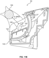
- Fig. 11B shows the first control element 142 in the second end position
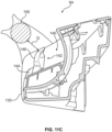
- Fig. 11C shows the first control element 142 in the default position. While the first control element 142 is in the first end position shown in Fig. 11A , the gap G is a first distance that is greater than the minimum clearance distance (depicted in Fig. 11A as MCD). While the first control element 142 is in the second end position shown in Fig.
- the gap G is a second distance less than the maximum reach distance (depicted in Fig. 11B as MRD). While the first control element 142 is in the default position shown in Fig. 11C , the gap G is a third distance intermediate the first and second distances.
- the second operator control assembly 64 includes a replacement control element 142' and a replacement grip member 150', also referred to herein as a second control element 142' and a second grip member 150'.
- Each of the second control element 142' and the second grip member 150' have at least one of different dimensions and/or different configurations than the first control element 142 and the first grip member 150.
- Fig. 11D shows the second control element 142' in the first end position
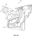
- Fig. 11E shows the second control element 142' in the second end position
- Fig. 11F shows the second control element 142' in the default position. While the second control element 142' is in the first end position shown in Fig.
- the gap G is a first distance that is greater than the minimum clearance distance (depicted in Fig. 11D as MCD'). While the second control element 142' is in the second end position shown in Fig. 11E , the gap G is a second distance less than the maximum reach distance (depicted in Fig. 11E as MRD'). While the second control element 142' is in the default position shown in Fig. 11F , the gap G is a third distance intermediate the first and second distances.
- One of the first control element 142 or the first grip member 150 may also be used with one of the second control element 142' or the second grip member 150', wherein the two installed components are always spaced from one another such that the gap G is greater than or equal to the minimum clearance distance and less than or equal to the maximum reach distance.
- Additional replacement control elements and/or grip members (not specifically shown) having at least one of different dimensions and/or configurations than the first and second control elements 142, 142' and grip members 150, 150' may also be installed, wherein the two installed components are always spaced from one another such that the gap G is greater than or equal to the minimum clearance distance and less than or equal to the maximum reach distance.
- the curvilinear shape of the housing recess 140 takes part in allowing different control elements to be used while maintaining the gap G within the aforementioned range, since the curvilinear shape at least in part sets the angle of the installed control element relative to the grip member. That is, positioning the control element in different locations along the curved surface of the curvilinear shape of the housing recess 140 and/or using control element base portions having different dimensions and/or configurations will modify the angle of the control element relative to the grip member.
- the grip member 150 may include an additional control element 160 as shown in Figs. 2 , 9 , 10A, and 10B .
- the additional control element 160 may generate control signals to the vehicle processor or controller to control a vehicle function such as, for example, the traveling direction of the vehicle 10, i.e., the vehicle processor or controller may control a traction motor of the vehicle 10 based on the control signals from the control element 160 to set the traveling direction of the vehicle 10.
- the operator control system 60 may optionally include first and second fixture structures 180, 182 to selectively allow one or both of the first and/or second operator control assemblies 62, 64 to be positioned in multiple respective positions.
- the first and second fixture structures 180, 182 may be coupled to or integral with the respective first and second support structures 52, 54.
- the first fixture structure 180 comprises a mounting plate 184 coupled to or integral with the first support structure 52.
- the mounting plate 184 may be an elongate plate extending in the vertical direction from the first support structure 52 to the first housing 66 of the first operator control assembly 62.
- the first fixture structure 180 further comprises a plurality of fasteners 186, such as bolts, that selectively extend through first openings 188A or second openings 188B provided in the mounting plate 184 and into corresponding openings 190 formed in the backside of the first housing 66 to couple the first housing 66 to the first support structure 52.
- the first fixture structure 180 can support the first operator control assembly 62 in a first orientation relative to the first support structure 52 shown in Figs.
- the first fixture structure 180 can support the first operator control assembly 62 in a second orientation relative to the first support structure 52, the second orientation different than the first orientation, as shown in Figs. 12A and 13A by inserting the fasteners 186 through the second openings 188B in the mounting plate 184 and into the openings 190 in the first housing 66.
- the first operator control assembly 62 While in the first orientation, the first operator control assembly 62 is positioned at a first angular orientation relative to the first support structure 52, and while in the second orientation, the first operator control assembly 62 is positioned at a second angular orientation relative to the first support structure 52 different than the first angular orientation.
- the first operator control assembly 62 When moved from the first angular orientation to the second angular orientation, the first operator control assembly 62 is rotated about a first axis A 1 (see Fig. 7 , noting that the first axis A 1 extends into the page in the views illustrated in Figs. 12A-13B ) that is generally parallel to the longitudinal axis L A of the vehicle 10.
- the first operator control assembly 62 may move through an angle of about -10 degrees to about 10 degrees relative to the vertical direction when moving from the first angular orientation to the second angular orientation, and according to another non-limiting exemplary working embodiment, the first operator control assembly 62 may move through an angle of about -5 degrees to about 5 degrees relative to the vertical direction when moving from the first angular orientation to the second angular orientation.
- the upper surface 52A of the first support structure 52 may be a curved upper surface 52A, which corresponds to a curved lower surface 66A of the first housing 66.
- the corresponding curved surfaces 52A, 66A allow the first operator control assembly 62 to be moved between the first and second orientations while maintaining a close fit between the first support structure 52 and the first housing 66.
- the second fixture structure 182 comprises a mounting plate 204 coupled to or integral with the second support structure 54.
- the mounting plate 204 may be an elongate plate extending in the vertical direction from the second support structure 54 to the second housing 130 of the second operator control assembly 64.
- the second fixture structure 182 further comprises a plurality of fasteners 206, such as bolts, that selectively extend through first openings 208A or second openings 208B provided in the mounting plate 204 and into corresponding openings 210 formed in the backside of the second housing 130 to couple the second housing 130 to the second support structure 54.
- the second fixture structure 182 can support the second operator control assembly 64 in a first orientation relative to the second support structure 54 shown in Figs. 12B and 13D by inserting the fasteners 206 through the first openings 208A in the mounting plate 204 and into the openings 210 in the second housing 130, or the second fixture structure 182 can support the second operator control assembly 64 in a second orientation relative to the second support structure 54, the second orientation different than the first orientation, as shown in Fig. 12A and 13C by inserting the fasteners 206 through the second openings 208B in the mounting plate 204 and into the openings 210 in the second housing 130.
- the second operator control assembly 64 While in the first orientation, the second operator control assembly 64 is positioned at a first angular orientation relative to the second support structure 54, and while in the second orientation, the second operator control assembly 64 is positioned at a second angular orientation relative to the second support structure 54 different than the first angular orientation.
- the second operator control assembly 64 When moved from the first angular orientation to the second angular orientation, the second operator control assembly 64 is rotated about a second axis A 2 (see Fig. 9 , noting that the second axis A 2 extends into the page in the views illustrated in Figs. 12A , 12B , 13C, and 13D ) that is generally parallel to the longitudinal axis L A of the vehicle 10.
- the second operator control assembly 64 may move through an angle of about -10 degrees to about 10 degrees relative to the vertical direction when moving from the first angular orientation to the second angular orientation, and according to another non-limiting exemplary working embodiment, the first operator control assembly 62 may move through an angle of about -5 degrees to about 5 degrees relative to the vertical direction when moving from the first angular orientation to the second angular orientation.
- the first and second support structures 52 and 54 may be positioned closer to one another in a narrow width vehicle, e.g., vehicles having a width equal to or less than 40 inches, and further away from one another in a wide width vehicle, e.g., vehicles having a width equal to or greater than 42 inches.
- the first operator control assembly 62 may be positioned in the first angular orientation (shown in Fig. 12B ), and to provide preferred ergonomic hand positioning for a wider width vehicle, the first operator control assembly 62 may be positioned in the second angular orientation (shown in Fig. 12A ).
- the upper surface 54A of the second support structure 54 may be a curved upper surface 54A, which corresponds to a curved lower surface 130A of the second housing 130.
- the corresponding curved surfaces 54A, 130A allow the second operator control assembly 64 to be moved between the first and second orientations while maintaining a close fit between the second support structure 54 and the second housing 130.
- Fig. 14 illustrates a second operator control assembly 64 according to additional embodiments.
- the second operator control assembly 64 according to Fig. 14 comprises a second housing 130 and one or more control elements 132, such as buttons, switches, levers, etc., provided on a control element area 134 of the second housing 130 for generating control signals to the vehicle processor or controller to control respective functions of the vehicle 10, such as, for example, an emergency stop, a control for an interactive display, etc. i.e., the vehicle processor or controller may control functions of the vehicle based on the control signals from the control elements 132.
- the control element area 134 may include any number of control elements or no control elements.
- the operator control assembly 64 further comprises a housing recess 140 that extends downwardly from the control element area 134 in a direction toward the floor surface 40 of the operator compartment 16.
- the housing recess 140 may have a curvilinear shape.
- a chamfered surface 141 extends around the outer periphery of the housing recess 140 in this embodiment, between the housing recess 140 and the control element area 134.
- the chamfered surface 141 may allow an operator increased space for reaching a control element 142 that is mounted to the second housing 130 and extends outwardly from the housing recess 140.
- the control element 142 may have an enlarged tip portion 142A distal from the base portion 144 compared to the control element 142 described above for Fig. 9 but may otherwise be the same or similar to the control element 142 described above for Fig. 9 and will not be described in detail herein.
- An elongate grip member 150 may be the same or similar to the grip member 150 described above for Fig. 9 , but the grip member 150 of Fig. 14 may include an additional control element 151 located thereon, such as a horn button.
- Fig. 15 illustrates a materials handling vehicle 310 constructed in accordance with embodiments.
- the vehicle 310 comprises a stockpicker, but could be another type of materials handing vehicle.
- the vehicle 310 includes a power unit 312, a platform assembly 314 including an operator compartment 316, and a load handling assembly 318.
- the power unit 312 includes a power source, such as a battery unit 320.
- the vehicle 310 includes a plurality of wheels 322 on which the vehicle 310 travels (one or more additional wheels are located underneath the power unit 312 but are not shown in Fig. 15 ).
- the load handling assembly 318 comprises a mast assembly 330 coupled to the power unit 312 on which the platform assembly 314 moves vertically.
- a fork structure 332 comprises a pair of forks 332A, 332B, which are coupled to the platform assembly 314 or mast assembly 330 for movement with the platform assembly 314.
- the mast assembly 330 comprises one or more mast sections. Mast sections may also be referred to herein as mast weldments.
- the exemplary mast assembly 330 illustrated in Fig. 15 is a three-stage mast assembly comprising first, second and third mast sections or weldments 330A-330C, see also Fig. 19A .
- the platform assembly 314 is attached to and moves relative to the third mast section or weldment 330C via a carriage 314B with rollers (only studs on which the rollers are mounted are illustrated in Fig. 17 ), see Fig.
- the ram causes the second mast section 330B to move relative to the first mast section 330A and also causes the third mast section 330C to move via the chain relative to the first and second mast sections 330A and 330B.
- the third mast section 330C raises twice the distance.
- the mast assembly 300 is illustrated in its fully retracted home position in Figs. 15 and 25 , and in its fully extended state in Fig. 26 .
- the platform assembly 314 is positioned in its fully retracted state in Fig. 15 .
- an upper portion 331A-331C of each of the first, second and third mast sections 330A-330C extends above an upper section 314A of the platform assembly 314, see Fig. 15 .
- the upper portion 331A-331C of each of the first, second and third mast sections 330A-330C extends above an upper part 362A of first operator control assembly 362 and/or an upper part 364A of second operator control assembly 364, see Figs. 15 and 20 .
- the operator compartment 316 includes a floor surface 340 upon which an operator stands while operating the vehicle 310 from an operator station 342 located in the operator compartment 316.
- An operator presence sensor 344 in the form of a pressure switch that senses an operator's foot is provided in the floor surface 340.
- the floor surface 340 may also be referred to herein as the floorboard. According to embodiments, one or more functions of the vehicle, such as traveling movement, raising/lowering the load handling assembly 318, etc. may be disabled unless the operator presence sensor indicates the presence of the operator in the operator compartment 316.
- First and second side restraints 346, 348 are provided at opposed left and right sides LS', RS' of the operator compartment 316, the left and right sides LS', RS' being spaced apart from one another in a lateral direction L D ' that is perpendicular to a longitudinal axis L A' of the vehicle 310.
- a support wall 324 is connected to the floorboard and positioned adjacent to and spaced from the mast assembly 330, further defining the operator compartment 316 of the platform assembly 314.
- the support wall 324 may also be referred to herein as an "inner support wall.”
- the operator station 342 may include one or more bins 350 in which the operator can store items.
- the bins 350 may be positioned anywhere in the operator station 342 and may be movable as desired.
- the operator station 342 may further comprise a first support structure 352 and a second support structure 354 spaced apart from each other in the lateral direction L D ', see Fig. 15 .
- the first and second support structures 352, 354 are separated by a recessed portion 356 of the vehicle 310 that defines an open area between the first and second support structures 352, 354.
- the open area extends to just above one of the bins 350 but could extend further towards the floor surface 340 if the bin 350 below the open area is not provided.
- An operator control system 360 is provided in the operator station 342.
- the operator uses the operator control system 360 to drive the vehicle 310 and to control one or more other vehicle functions.
- the operator control system 360 comprises the first operator control assembly 362 associated with the first support structure 352 and the second operator control assembly 364 associated with the second support structure 354.
- the first operator control assembly 362 is provided to control steering of the vehicle 310 and optionally to control additional vehicle functions
- the second operator control assembly 364 is provided to control load handling assembly lift and lower functions, direction and speed control and optionally other vehicle functions.
- the first operator control assembly 362 and second operator control assembly 364 are coupled to the support wall 324 and positioned to allow for operation by an operator located within the operator compartment 316.
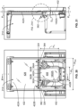
- a non-horizontal viewing window 402 which may also be referred to as a "mid window” or “first viewing window,” is provided in the support wall 324 comprising an upper end 402A and lower end 402B, wherein the lower end 402B extends or is positioned below a lower part 362B of the first operator control assembly 362 and/or a lower part 364B of the second operator control assembly 364 to maximize downward viewing by the operator, see Figs. 15 and 20 .
- the non-horizontal viewing window 402 may be positioned between the first operator control assembly 362 and second operator control assembly 364 in the illustrated embodiment.
- the viewing window upper end 402A may be below, on level with, or extend above the upper part 362A of first operator control assembly 362 and/or the upper part 364A of second operator control assembly 364.
- non-horizontal means that the viewing window 402 has a vertical dimension greater than a horizontal dimension.
- the non-horizontal viewing window 402 has a vertical dimension Hv between 18 inches and 22 inches, see Fig. 20 .
- the viewing window 402 appears as a generally rectangular or a tapered generally trapezoidal shape and its corners, sides and edges may vary provided that the shape of viewing window 402 is defined to maximize downward visibility.
- the sides and corners of window 402 may be linear or curvilinear to achieve this purpose. It is also contemplated that the viewing window 402 may comprise any other shape such as a circle, oval, square, triangle, etc.
- the width Wv of the non-horizontal viewing window 402 may be equal to between 30% to 50% of the overall width Wsw of the support wall 324, see Fig. 20 .
- the non-horizontal viewing window 402 is illustrated in Figs. 15 and 20 as centered on the support wall 324 between generally the left side LS' and right side RS' of the operator compartment 316, but may be positioned horizontally at any location in the support wall 324 as required to maximize downward viewing by the operator between the first operator control assembly 362 and the second operator control assembly 364, and between the first support structure 352 and the second support structure 354.
- the non-horizontal viewing window 402 may comprise a clear pane 406 of suitable material, such as clear polymer, glass, mesh-reinforced glass or, as in the embodiment of Fig. 22 , a see-through screen 408.
- the support wall 324 and the non-horizontal viewing window 402 are in a generally vertical orientation in the platform assembly 314.
- the non-horizontal viewing window 402 is shown in Figs. 21 and 23 positioned in a first vertical plane Pv.
- generally vertical orientation it is appreciated that “vertical” is relative to the floor surface 340 of the vehicle which lies on the generally horizontal plane of Hp' when the vehicle is located on level ground.
- the non-horizontal viewing window 402 and adjacent portions of the support wall 324 may also be angled away from the mast assembly 330 at the viewing window lower end 402B and protrude slightly into the recessed portion 356 of the operator compartment to enhance the ease of viewing through the non-horizontal viewing window 402 particularly for embodiments that include a see-through screen 408 as in Fig. 22 .
- the support wall 324 may extend back towards the first vertical plane Pv so that the recessed portion 356 below the non-horizontal viewing window 402 remains open for use by the operator.
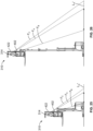
- Figs. 19A and 19B illustrate the relationship between the non-horizontal viewing window 402, the support wall 324, and the mast assembly 330.
- An inner edge 430 of the third mast section or mast weldment 330C i.e., the edge of the mast assembly 330 closest to the viewing window 402, defines an inner mast assembly vertical plane P M , see Figs. 19A and 19B .
- An outer surface 404 of the non-horizontal viewing window 402 is located a small distance Dv from the inner mast assembly vertical plane P M , which distance Dv may be between 0.5 inches to 2 inches.
- the operator of the materials handling vehicle 310 may see, without bending, through the non-horizontal viewing window 402 along view lines F A and F B , enabling the operator to view forward areas left, right and along longitudinal axis L A ' of vehicle 310.
- View line F B extends from the operator's eye through the lower end 402B of non-horizontal viewing window 402
- view line F A extends from the operator's eye through the upper end 402A of non-horizontal viewing window 402. It is noted that the location of the view lines F A and F B may change based on operator height and position. Depending on the elevation of the platform assembly 314, the view area between view lines F A and F B may be steeper and narrower or less steep and broader.
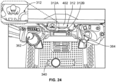
- the view area may advantageously include the power unit 312, such as left and right corners 312A and 312B of the power unit 312, as illustrated from the operator's perspective in Fig. 24 .
- the view in Fig. 24 may be from the operator's point of view while standing without leaning with the platform assembly 314 in the elevated position of Fig. 25 but may also be from an operator's point of view with the platform assembly 314 in the elevated position of Fig. 26 if the operator leans forward so as to be close to the viewing window 402.
- the materials handling vehicle 310 may include a second viewing window 422 located above the non-horizontal viewing window 402.
- an inner surface 422A of the second viewing window 422 is positioned in a second generally vertical plane Po, that represents the inner face closest to the operator of the second viewing window 422.
- An inner surface 1402A of the first viewing window 402 is positioned in the first vertical plane Pv.
- Second vertical plane Po may be spaced from the first vertical plane Pv, wherein the inner surface 1402A positioned in the first vertical plane Pv represents the inner face closest to the operator of the first, non-horizontal viewing window 402.
- the first vertical plane Pv is located closer to the mast assembly 330 than the second vertical plane Po.
- Figs. 20-23 illustrate that the space or distance D O between the first vertical plane Pv and second vertical plane Po may vary depending on whether the second viewing window 422 comprises a second transparent pane 426 or a second see-through screen 428 and the configuration thereof, and embodiments include a space D O of from 0.1 inches to 3 inches (transparent pane), and from 0.25 inches to 2.5 inches (screen). It is also contemplated that the first vertical plane Pv and the second vertical plane Po may comprise the same plane.
- the second viewing window 422 may comprise a clear pane 426 of suitable material, see Figs.
- first viewing window 402 may comprise a polymeric, e.g., plexiglass, pane and the second viewing window 422 may comprise a glass pane.
- the operator of materials handling vehicle 310 may see through a lower portion of the second viewing window 422 downward along view line Fc and forward to the horizon and above, and left, right and along longitudinal axis L A ' of vehicle 310.
- the area viewed along view line Fcfrom the same operator position as described above for view lines F A and F B begins further outward from the materials handling vehicle 310 along longitudinal axis L A ' than the area viewed through the non-horizontal viewing window 402, as illustrated in Figs. 25 and 26 .
- the upper section 314A of the platform assembly 314 additionally includes an overhead guard assembly 500 that is positioned over the operator compartment 316.
- the overhead guard assembly 500 comprises a base frame 502 that includes first and second side bar members 502A, 502B, a front bar member 502C, and a back bar member 502D, see also Figs. 16 and 17 .
- the bar members 502A, 502B, 502C, 502D may be formed separately and joined together, e.g., by welding or bolting, or one or more of the bar members 502A, 502B, 502C, 502D may be formed integrally together as a single structure.
- the first, second, and front bar members 502A, 502B, 502C are integrally formed as a single structure that is joined to the back bar member 502D.
- One or more spanning members may span between the first and second side bar members 502A, 502B or the front and back bar members 502C, 502D to separate a central opening 502E defined by the base frame 502 into smaller sections.
- a transparent window may be used in place of the spanning members to allow an operator in the operator compartment 316 who is looking up to see through the central opening 502E.
- the overhead guard assembly 500 may further comprise first and second extension members 504A, 504B that extend laterally from the respective first and second side bar members 502A, 502B.
- the extension members 504A, 504B effect an increase in a lateral width L WG of the overhead guard assembly 500, see Fig. 16 .
- Front and back corner portions 506A 1 , 506A 2 , 506B 1 , 506B 2 of the first and second extension members 504A, 504B provide the overhead guard assembly 500 with angled surfaces at its corners.
- First and second extension members 504A, 504B having different lateral widths are shown in Figs. 17A-17C .
- the first and second extension members 504A, 504B selected for use on a particular vehicle 310 may be chosen based on a lateral width L WF of the floor surface 340 (see Fig. 15 ) of the operator compartment 316, e.g., the lateral width L WG of the overhead guard assembly 500, including the first and second extension members 504A, 504B, may be generally equal to the lateral width L WF of the floor surface 340.
- the lateral width L WG of the overhead guard assembly 500 may be greater than the lateral width L WF of the floor surface 340.
- the first and second extension members 504A, 504B shown in Figs. 17A-17C also have the angled front and back corner portions 506A 1 , 506A 2 , 506B 1 , 506B 2 , and the first and second extension members 504A, 504B shown in Figs. 17A-17B additionally include spanning members 508 that separate openings defined in an interior portion of the first and second extension members 504A, 504B into smaller sections.
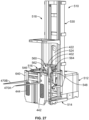
- the vehicle 510 may include a power unit 512, a platform assembly 514, and a load handling assembly 518 with a mast assembly 530, which may be substantially similar to the vehicles 10 and 310 described herein.
- An operator compartment 516 may be at least partially defined by an inner support wall 524 including an inner viewing window 402, a floorboard 540 that defines a generally horizontal floor surface of the vehicle 510, and an outer support wall 640, in which the outer support wall 640 is connected to the floorboard 540 and opposite the inner support wall 524.
- First and second side restraints 546, 548 are provided on either side of the vehicle 510.
- a first operator control system 560 (also referred to herein as an inner operator control system) is coupled to the inner support wall 524 and may comprise a first inner operator control assembly 562 and a second inner operator control assembly 564.
- a second operator control system 660 (also referred to herein as an outer operator control system) is coupled to the outer support wall 640 and may comprise a first outer operator control assembly 662 and a second outer operator control assembly 664.
- the first and second operator control systems 560 and 660 are positioned to allow for operation by an operator located within an operator compartment 516 of the vehicle 510, as described herein in more detail.
- At least one outer viewing window 442 or 444 is positioned in the outer support wall 640.
- First outer viewing window 442 and second outer viewing window 444 are located below the operator control assemblies 662, 664 of the outer operator control system 660 and spaced apart laterally a distance D P , see Fig. 28 .
- First outer viewing window 442 has an upper end 442A and a lower end 442B
- second outer viewing window 444 has an upper end 444A and a lower end 444B.
- Each of the first and second outer viewing windows 442, 444 may comprise a clear pane 446 of suitable material, such as clear polymer, glass, mesh-reinforced glass, as illustrated in Fig. 28 , or a see-through screen 448 as illustrated in Fig. 30 .
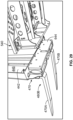
- a fork carriage assembly 470 is coupled to the outer support wall 640 and includes first and second forks 470A and 470B and a movable fork carriage 471 to which the forks 470A and 470B are coupled for movement with the movable fork carriage 471.
- a ram/cylinder assembly 474 is provided for moving the fork carriage 471 and forks 470A and 470B vertically relative to the outer support wall 640.
- the fork carriage 471 includes rollers 472 that move within tracks of rails 642 forming part of the outer support wall 640, see Fig. 28A .
- the cylinder 474A of the ram/cylinder assembly 474 is fixed to a base member 644 of the outer support wall 640, see Figs. 28 and 29 .
- the ram 474B of the ram/cylinder assembly 474 may be fixed to the fork carriage assembly 470 such that movement of the ram 474B effects movement of the fork carriage assembly 470.
- a chain (not shown) may be fixed at one end to the cylinder 474A and at a second end to the fork carriage assembly 470.
- a roller may be fixed to an end of the ram 474B which roller engages the chain to effect lift of the fork carriage assembly 470.
- the operator of materials handling vehicle 510 may see, without bending, through outer viewing windows 442, 444 along view lines R A and R B , enabling the operator to view rearward areas, also referred to as "fork facing areas," to the left, right and rearward along the longitudinal axis L A ' of vehicle 510.
- View lines R B extend from the operator's eye through the lower ends 442B and 444B of viewing windows 442, 444, respectively; and view lines R A extend from the operator's eye through the upper end 442A, 444A of viewing windows 442, 444. It is noted that the location of the view lines R A and R B may change based on operator height and position. Depending on the elevation of the platform assembly 514, the view area between view lines R A and R B may be steeper and narrower or less steep and broader as illustrated from the operator's perspective in Fig. 31 .
- the inner and outer operator control systems 560, 660 of the materials handling vehicle 510 of Figs. 27-31 will be described in more detail (the side restraints 546, 548 are removed to illustrate other aspects in detail).
- the operator stands on the floorboard 540 in the operator compartment 516 at one of a first operator station 542 (also referred to herein as an inner operator station) or a second operator station 543 (also referred to herein as an outer operator station).
- An operator presence sensor 544 e.g., a pressure switch, is provided in the floorboard 540 and senses an operator's foot. As described herein, one or more functions of the vehicle may be disabled unless the operator presence sensor 544 indicates the presence of the operator in the operator compartment 516.
- the inner operator station 542 may be substantially similar to the operator station 42, 342 described herein and may comprise a first support structure 552 and a second support structure 554.
- the first and second support structures 552, 554 may be spaced apart from each other in a lateral direction L D" that is perpendicular to a longitudinal axis L A" of the vehicle 510.
- the first and second support structures 552, 554 are separated by a recessed portion 556 of the vehicle 510 that defines an open area extending downward from upper surfaces (not labeled) of the first and second support structures 552, 554 toward the floorboard 540.
- the inner operator control system 560 comprises the first and second operator control assemblies 562, 564, which are provided at the inner operator station 542 and are coupled to the inner support wall 524 to allow for operation by an operator located at the inner operator station 542, e.g., by an operator facing toward the inner support wall 524.
- the first and second operator control assemblies 562, 564 are used to drive the vehicle 510 and to control one or more other vehicle functions, as described in detail herein.
- first operator control assembly 562 is provided to control steering of the vehicle 510 and optionally to control additional vehicle functions
- second operator control assembly 564 is provided to control a traveling direction of the vehicle 510, load handling assembly lift and lower functions, and optionally other vehicle functions, as described in greater detail herein above in relation to first and second operator control assemblies 62, 64.
- the first operator control assembly 562 may be substantially similar to the first operator control assembly 62, as described herein.
- the first operator control assembly 562 is associated with the first support structure 552 and comprises a first housing 566 that may be separate from, but mounted to, the first support structure 552 via fasteners, adhesive, etc. In other examples, the first housing 566 may be integral with a portion of the first support structure 552 (see Fig. 2A ).
- the first operator control assembly 562 further comprises a steering assembly 580. As described in detail herein with respect to the first operator control assembly 62 and the steering assembly 80, the steering assembly 580 is movable between a first position (shown in Fig. 33 ) and a second position (shown in Fig. 36 ) and may be locked in these two positions via a lock assembly (not labeled).
- the second operator control assembly 564 may be substantially similar to the second operator control assembly 64, as described herein.
- the second operator control assembly 564 is associated with the second support structure 554 and comprises a second housing 582 that may be separate from, but mounted to, the second support structure 554 via fasteners, adhesive, etc.
- the second housing 582 may be integral with the second support structure 554 (see Fig. 2A ).
- the second operator control assembly 564 comprises a housing recess 646 that extends downwardly in a direction toward the floorboard 540 of the operator compartment 516 (see Fig.
- control element 648 mounted to the second housing 582 and extends outwardly from the housing recess 646; and an elongate grip member 650 mounted to the second housing 582 and extending over the housing recess 646.
- the control element 648 and elongate grip member 650 may be substantially similar to the control element 142 and elongate grip member 150 of the second operator control assembly 64, and one or both of the control element 648 and the elongate grip member 650 may be removed and replaced with a replacement control element and/or replacement grip member (not shown) having different dimensions and/or different configurations than the original (replaced) control element 648 and/or elongate grip member 650 (see Figs. 10A-11F ).
- first and second operator control assemblies 562, 564 may optionally be mounted to the first and second support structures 552, 554 to allow the first and/or second operator control assemblies 562, 564 to be positioned in multiple respective positions relative to the first and second support structures 552, 554.
- first and second operator control assemblies 562, 564 may comprise respective first and second fixture structures 680, 682, e.g., mounting plates 684, 704, which may be substantially similar to the mounting plates 184, 204 associated with the first and second operator control assemblies 62, 64, respectively.
- the mounting plates 684, 704 may support the first and second operator control assemblies 562, 564 in respective first and second angular orientations relative to the first and second support structures 552, 554 (see Figs. 12A-13D ). Also as described herein, the first and second support structures 552, 554 may be positioned closer to one another in a narrow width vehicle and further away from one another in a wide width vehicle. The angular orientation of one or both of the first and second operator control assemblies 562, 564 may be selected to provide preferred ergonomic hand positioning for a narrower width vehicle or a wider width vehicle.
- a vertical position of the first and second operator control assemblies 562, 564 relative to the floorboard 540 may be adjustable to achieve ergonomic positioning for operators of varying dimension (e.g., height, arm length, etc.) and to accommodate operator preference.
- the first support structure 552 may comprise a fixed housing portion 552A and a movable housing portion 552B that is movable relative to the fixed housing portion 552A.
- the second support structure 554 may similarly comprise a fixed housing portion 554A and a movable housing portion 554B that is movable relative to the fixed housing portion 554A.
- the movable housing portions 552B, 554B may be positioned to telescope over the respective fixed housing portions 552A, 554A as the vertical position of the first and second operator control assemblies 562, 564 is adjusted.
- the first operator control assembly 562 and movable housing portion 552B in Fig. 33 are shown in a lowered position with solid lines, and an outline of the first operator control assembly 562 and movable housing portion 552B in a raised position is indicated with dashed lines.
- the second operator control assembly 564 and movable housing portion 554B are shown in a raised position with solid lines, and an outline of the second operator control assembly 564 and movable housing portion 554B in a lowered position is indicated with dashed lines.
- the first operator control assembly 562 may be fixedly coupled to the movable housing portion 552B, such that the first operator control assembly 562 and movable housing portion 552B move together
- the second operator control assembly 564 may similarly be fixedly coupled to the movable housing portion 554B, such that the second operator control assembly 564 and movable housing portion 554B move together.
- the first and second operator control assemblies 562, 564 may each be movable continuously between respective raise and lowered positions to allow the first and second operator control assemblies 562, 564 to be arranged at a desired vertical position.
- the first operator control assembly 562 and movable housing portion 552B when moving between the lowered position and the raised position, may be movable by a distance D 1 .
- the second operator control assembly 564 and movable housing portion 554B when moving between the lowered position and the raised position, may similarly be movable by a distance D 2 .
- the distances D 1 and D 2 may be between about 0.1 to about four inches.
- a first vertical adjustment assembly 800 for selectively supporting the first operator control assembly 562 at a plurality of vertical positions is illustrated.
- the first vertical adjustment assembly 800 is coupled to the first operator control assembly 562 to provide for movement of the first operator control assembly 562 in a vertical direction indicated by arrow A relative to the floorboard 540 (see Fig. 32 ) and relative to the fixed housing portion 552A.
- the first vertical adjustment assembly 800 may comprise a first mounting plate 802 that fixedly couples the first vertical adjustment assembly 800 to the inner support wall 524.
- the first mounting plate 802 may comprise a plurality of openings 804 and a plurality of fasteners 806 such as bolts, which extend through the openings 804 and are received in corresponding openings (not shown) formed in the inner support wall 524 to attach the first mounting plate 802 to the inner support wall 524.
- the first mounting plate 802 may be welded or otherwise attached to the inner support wall 524.
- the first vertical adjustment assembly 800 may further comprise a rail member 808 that is coupled to the first mounting plate 802.
- a plurality of fasteners 812 such as bolts may extend through a plurality of openings 814 formed in the first mounting plate 802 and may be received in corresponding openings 810 formed in the rail member 808 to attach the rail member 808 to the first mounting plate 802.
- the rail member 808 may be welded or otherwise attached to the first mounting plate 802.
- the fixture structure 680 i.e., the mounting plate 684, of the first operator control assembly 562 may be coupled to the first mounting plate 802 and to the rail member 808 via a carriage assembly 816.
- the mounting plate 684 may comprise a plurality of openings 820, and a plurality of fasteners 818 may extend through the openings 820 and may be received in corresponding openings 822 formed in the carriage assembly 816 to couple the mounting plate 684 to the carriage assembly 816.
- the carriage assembly 816 may be movably coupled to the rail member 808 via a plurality of linear bearing blocks 824.
- the linear bearing blocks 824 may be coupled to the carriage assembly 816 via a plurality of fasteners 826, which extend through a plurality of openings 828 formed in the carriage assembly 816 and are received in corresponding opening 830 formed in the linear bearing blocks 824. As described herein in more detail, the linear bearing blocks 824 slide vertically along the rail member 808 to effect vertical movement of the carriage assembly 816.
- the rail member 808 comprises first and second rails 808A, 808B
- the carriage assembly 816 comprises four linear bearing blocks 824.
- a first pair of the linear bearing blocks 824 engage the first rail 808A
- a second pair of the linear bearing blocks 824 engage the second rail 808B.
- the rail member 808 may comprise a single rail or three or more rails, and the number of linear bearing blocks 824 may be varied as desired to achieve a stable coupling between the carriage assembly 816 and the rail member 808.
- Cables, wiring, etc. (not shown) extending between the first operator control assembly 562 and the vehicle electronic processor or controller provide control signals to the electronic processor/controller to control respective functions of the vehicle 510.
- the carriage assembly 816 may optionally comprise one or more cable guides 878 that secure the cables and prevent them from interfering with vertical movement of the first operator control assembly 562.
- the first mounting plate 802 may be coupled to the fixed housing portion 552A of the first support structure 552.
- the first mounting plate 802 may comprise one or more extensions 864 with openings 866 formed therein.
- Fasteners 868 extend through spacers 870 and are received in the openings 866.
- the spacers 870 surround the fasteners 868, and upon receipt of the fasteners 868 in the openings 866, the spacers 870 may extend outward from an inner face (not labeled) of the first mounting plate 802, i.e., the portion of the first mounting plate 802 facing toward the operator compartment 516.
- the fixed housing portion 552A may comprise, for example, brackets (not labeled) that engage the first mounting plate 802 (e.g., the spacers 870 extending outward from the inner face) to secure the fixed housing portion 552A to the first mounting plate 802.
- the carriage assembly 816 may similarly be coupled to the movable housing portion 552B of the first support structure 552.
- the carriage assembly 816 may comprise one or more threaded bores (not visible) formed in an inner face and/or one or more side faces (not labeled), which receive fasteners 872 (only one fastener 872 is visible in Fig. 36 ).
- Each fastener 872 comprises a respective spacer 874, 876 that surrounds the fastener 872, and upon receipt of the fasteners 872 in the threaded bores, the spacers 874, 876 may extend outward from the inner and/or side face(s) of the carriage assembly 816.
- the movable housing portion 552B may comprise brackets (not labeled) that engage the carriage assembly 816 (e.g., the spacers 874, 876 extending outward from the inner and/or one or more side faces) to secure the movable housing portion 552B to the carriage assembly 816 (the spacers 874 extending outward from the side faces of the carriage assembly 816 may be seen in Fig. 34 ).
- the first vertical adjustment assembly 800 further comprises a locking gas spring 832 that controls the vertical position and movement of the carriage assembly 816 and the mounting plate 684 (and thus the first operator control assembly 562) relative to the first mounting plate 802 and the rail member 808.
- the locking gas spring 832 may comprise a rod 834 and a cylinder 836.
- One end of the cylinder 836 comprises a fitting 838 that engages a protrusion 840 formed on the mounting plate 684.
- a snap ring (not labeled) may be used to secure the fitting 838 to the protrusion 840.
- a receiver 844 may be coupled to the first mounting plate 802 by, for example, a fastener 848 that extends through an opening 852 and is received in an internally threaded bore of a standoff 854.
- An opposing end of the rod 834 which may comprise a release valve 842, is inserted into an opening 844A formed in the receiver 844.
- the receiver 844 comprises a slot 844B that receives a cam 850.
- An opening 844C is formed through the portion of the receiver 844 comprising the slot 844B, and a pin 846 extends through the opening 844C and through an opening 850A formed in the cam 850 to pivotably secure the cam 850 to the receiver 844.
- a lower portion of the opening 844A may be in communication with the slot 844B, such that when the rod 834 of the locking gas spring 832 is inserted into the opening 844A, an extension 850C of the cam 850 is positioned adjacent to, or in contact with, the release valve 842.
- a lever 860 is positioned below the locking gas spring 832 and is coupled to the receiver 844 and to the cam 850 to operate the release valve 842 of the locking gas spring 832.
- the lever 860 comprises a fixed end 860-1 and a free end 860-2.
- the standoff 854 may extend through an opening 844D formed in the receiver 844 and through an opening 860A formed in the fixed end 860-1 of the lever 860.
- a snap ring (not labeled) may be used to secure the fixed end 860-1 of the lever 860 to the receiver 844 and pivotably couple the lever 860 to the receiver 844.
- the fixed end 860-1 of the lever 860 comprises a protrusion 862 that is received in an opening 850B formed in the cam 850.
- the standoff 854 maintains the necessary spacing to prevent contact between the protrusion 862 and the first mounting plate 802.
- the free end 860-2 of the lever 860 is in a rest or first position, and the first operator control assembly 562 is in a lowered position, i.e., a first vertical position.
- An operator applies an upward force to the free end 860-2 of the lever 860, as indicated by arrow B, to move the free end 860-2 of the lever 860 from the first position to a raised or second position shown in Figs. 35 and 37 .
- the fixed housing portion 552A may comprise a slot 553 that accommodates movement of the lever 860.
- Movement of the free end 860-2 of the lever 860 from the first to the second position causes the fixed end 860-1 of the lever 860 to rotate about an axis 880 shown in Fig. 37 .
- Engagement between the cam 850 and the protrusion 862 formed on the lever 860 causes the cam 850 to pivot, such that the extension 850C of the cam 850 moves upward and actuates, e.g., depresses, the release valve 842. Actuation of the release valve 842 unlocks the locking gas spring 832 and permits vertical movement of the first operator control assembly 562 in the direction indicated by arrow A.
- the mounting plate 684 moves upward with the cylinder 836 of the locking gas spring 832 due to the engagement between the fitting 838 and the protrusion 840 (a portion of the cylinder 836 is visible in Figs. 34 and 35 ).
- the carriage assembly 816 which is coupled to the mounting plate 684, slides upward along the rail member 808 via the linear bearing blocks 824, and the movable housing portion 552B, which is coupled to the carriage assembly 816, telescopes upward along the fixed housing portion 552A.
- the first operator control assembly 562 and the movable housing portion 552B (via the carriage assembly 816 and the mounting plate 684) move from the first vertical position shown in Figs. 34 and 36 toward a second vertical position, i.e., the raised position shown in Figs. 35 and 37 .
- the locking gas spring 832 may be configured such that the cylinder 836 immediately moves upward (i.e., away from the release valve 842) upon actuation of the release valve 842, without the need for the application of an additional force.
- the locking gas spring 832 may be configured such that an additional upward force is needed to effect upward movement, e.g., the operator may actuate the lever 860 with a foot or with one hand and may use the other hand to exert an additional upward force on the first operator control assembly, e.g., the first housing 566, to guide the first operator control assembly 562 to the desired position.
- the first vertical adjustment assembly 800 may optionally comprise one or more additional structures, e.g., a cable assembly (not shown) extending between the lever 860 and the locking gas spring 832, that actuate the release valve 842 to unlock the locking gas spring 832, and in some particular examples, the lever 860 may be positioned at a different location on the first support structure 552 or the first operator control assembly 562 (e.g., above all or part of the locking gas spring 832).
- additional structures e.g., a cable assembly (not shown) extending between the lever 860 and the locking gas spring 832, that actuate the release valve 842 to unlock the locking gas spring 832
- the lever 860 may be positioned at a different location on the first support structure 552 or the first operator control assembly 562 (e.g., above all or part of the locking gas spring 832).
- the operator releases the free end 860-2 of the lever 860.
- the free end 860-2 of the lever 860 returns to the first position, which disengages the extension 850C of the cam 850 from the release valve 842 and causes the locking gas spring 832 to lock, thereby fixing the first operator control assembly 562 in place.
- the operator moves the free end 860-2 of the lever 860 from the first position to the second position by applying an upward force in the direction indicated by arrow B with a foot or one hand, which depresses the release valve 842 and unlocks the locking gas spring 832.
- the operator then applies a downward force to the first operator control assembly 562, e.g., to the first housing 566, with the other hand to cause a downward movement of the first operator control assembly 562 in the direction indicated by arrow A.
- the mounting plate 684 and carriage assembly 816 move downward with the cylinder 836 of the locking gas spring 832, such that the first operator control assembly 562 and the movable housing portion 552B move from a first vertical position (in this case, the raised position shown in Fig. 35 ) toward a second vertical position (in this case, the lowered position shown in Figs. 34 and 36 ).
- the operator releases the free end 860-2 of the lever 860, which causes the locking gas spring 832 to lock again, thereby fixing the first operator control assembly 562 in place.
- the fixed housing portion 552A, the first mounting plate 802, and the rail member 808 remain stationary during adjustment of the first operator control assembly 562.
- the second operator control assembly 564 may comprise a second vertical adjustment assembly 900, which may be substantially similar to the first vertical adjustment assembly 800.
- the second vertical adjustment assembly 900 is coupled to the second operator control assembly 564 to selectively support the second operator control assembly 564 at a plurality of vertical positions and provide for movement of the second operator control assembly 564 in the vertical direction indicated by arrow A relative to the floorboard 540 (see Fig. 32 ) and relative to the fixed housing portion 554A.
- the second vertical adjustment assembly 900 may comprise a second mounting plate 902 that fixedly couples the second vertical adjustment assembly 900 to the inner support wall 524, as described with respect to the first mounting plate 802.
- the second vertical adjustment assembly 900 may further comprise a rail member and carriage assembly that are substantially similar to the rail member 808 and carriage assembly 816, in which the rail member is attached to the second mounting plate 902 and the carriage assembly is movably coupled to the rail member via a plurality of linear bearing blocks.
- the fixture structure 682, i.e., the mounting plate 704, of the second operator control assembly 564 as shown in Figs. 34 and 35 may be coupled to the second mounting plate 902 and the rail member via the carriage assembly.
- the second mounting plate 902 may be coupled to the fixed housing portion 554A of the second support structure 554.
- the second mounting plate 902 may comprise one or more extensions 964 that receive fasteners with spacers (not visible), and the fixed housing portion 554A may comprise brackets (not labeled) that engage the second mounting plate 902 (e.g., via the spacers) to secure the fixed housing portion 554A to the second mounting plate 902.
- the movable housing portion 554B of the second support structure 554 may be coupled to the carriage assembly.
- spacers 974 extending outward from side faces of the carriage assembly are visible in Fig. 34
- the movable housing portion 554B may comprise brackets (not labeled) that engage the carriage assembly (e.g., the spacers 974 extending outward from the side faces) to secure the movable housing portion 554B to the carriage assembly.
- the movable housing portion 554B may similarly comprise brackets that engage spaces extending outward from an inner face of the carriage assembly.
- the second vertical adjustment assembly 900 may comprise a locking gas spring (only a cylinder 936 of the locking gas spring is visible in Figs. 34 and 35 ), which may be substantially similar to the locking gas spring 832 described herein.
- the locking spring may be coupled to the mounting plate 704 of the second operator control assembly 564 to control the vertical position and movement of the carriage assembly and the mounting plate 704 (and thus the second operator control assembly 564) relative to the second mounting plate 902 and the rail member.
- the second vertical adjustment assembly 900 may further comprise a receiver and a cam, which may be substantially similar to the receiver 844 and cam 850 of the first vertical adjustment assembly 800.
- a lever 960 is coupled to the receiver and to the cam to operate a release valve of the locking gas spring and allow vertical movement of the second operator control assembly 564.
- the operator applies an upward force with a foot or with one hand to a free end 960-2 of the lever 960, as indicated by arrow B, to move the free end 960-2 from a rest or first position shown in Fig. 34 to a raised or second position shown in Fig. 35 .
- the fixed housing portion 554A may comprise a slot 555 that accommodates movement of the lever 960.
- the first and second operator control assemblies 562, 564 may be adjusted continuously between the lowered and raised positions and may be placed at any desired vertical position along a path of motion permitted by the first and second vertical adjustment assemblies 800, 900 to achieve ergonomic positioning for operators of varying heights and to accommodate operator preferences.
- the vertical positions of the first and second operator control assemblies 562, 564 may be adjusted independently of each other.
- adjustment of the vertical position of the first and second operator control assemblies 562, 564 may be used in conjunction with one or more of the other adjustment features described herein, including changing a position of the steering assembly 580 of the first operator control assembly 562, replacing one or more elements of the second operator control assembly 564, and/or adjusting an angular orientation of the first and/or second operator control assembly 562, 564 relative to the respective first and second support structures 552, 554.
- the steering assembly 580 is in the first position as shown in Figs.
- an operator may wish to place the first operator control assembly 562 at a lower vertical position, as compared to when the steering assembly 580 is in the second position as shown in Fig. 36 .
- the operator may also wish to adjust the vertical position of the first and/or second operator control assemblies 562, 564 based on whether the first and second operator control assemblies are positioned at the first or second angular orientation relative to their respective first and second support structures 552, 554 (see Figs. 12A to 13D ) and/or based on the dimension and/or configuration of replaceable elements in the second operator control assembly 564. All adjustments of the first and second operator control assemblies 562, 564 may be performed independently of each other.
- the outer operator control system 660 comprising the first and second operator control assemblies 662, 664 is provided at the outer operator station 543 and may be used as an alternative to the first operator control system 560 to drive the vehicle 510 and to control one or more other vehicle functions.
- the first and second operator control assemblies 662, 664 are coupled to the outer support wall 640 via one or more mounting brackets (not visible) and are positioned to allow for operation by an operator located at the outer operator station 543, e.g., by an operator facing toward the outer support wall 640 and the fork carriage assembly 470 (see also Fig. 31 ).
- the first and second operator control assemblies 662, 664 are spaced apart from each other in the lateral direction L D" and may be positioned, for example, on either side of the ram/cylinder assembly 474.
- the first operator control assembly 662 may be substantially similar to the first operator control assembly 62, 562 described herein and may comprise a first housing 666 and a steering assembly 780, which may be movable between a first position (shown in Figs. 28, 30 , and 32 ; see also Figs. 2 , 3 , and 5-7 ) and a second position (not shown; see Figs. 4 and 8 ).
- the second operator control assembly 664 may be substantially similar to the second operator control assembly 64, 564 described herein and may comprise a second housing 668, a housing recess 746, a control element 748, and an elongate grip member 750. One or both of the control elements 748 and the elongate grip member 750 may be removed and replaced with a replacement control element and/or replacement grip member (not shown) having different dimensions and/or different configurations.
- the first and/or second operator control assemblies 662, 664 may optionally be mounted to the outer support wall 640 such that the first and/or second operator control assemblies 662, 664 may be positioned at multiple angular orientations and/or multiple vertical positions.
- a dash 600 may extend between the first and second operator control assemblies 662, 664 and may define a horizontal support surface, which may be used as a work surface by the operator. As best seen in Figs. 28 and 30 , at least a portion of the first and second operator control assemblies 662, 664 may be recessed with respect to an upper surface 600A, 640A of the dash 600 and the outer support wall 640, respectively.
- the first and second operator control assemblies 662, 664 may be positioned such that a respective uppermost portion (e.g., the steering assembly 780 and the elongate grip member 750) of the first and second operator control assemblies 662, 664 is flush with, or recessed with respect to, the upper surfaces 600A, 640A of the dash 600 and outer support wall 640.
- the positioning of the first and second operator control assemblies 662, 664 below the upper surfaces 600A, 640A of the dash 600 and outer support wall 640 allows objects, e.g., boxes, to slide across the upper surfaces 600A, 640A without contacting the first and second operator control assemblies 662, 664.
- One or more trays 602, 604 may be provided adjacent to the first and/or second operator control assemblies 662, 664, which may be used by the operator to store items.
Landscapes
- Engineering & Computer Science (AREA)
- Transportation (AREA)
- Structural Engineering (AREA)
- Civil Engineering (AREA)
- Life Sciences & Earth Sciences (AREA)
- Geology (AREA)
- Mechanical Engineering (AREA)
- Combustion & Propulsion (AREA)
- Chemical & Material Sciences (AREA)
- Forklifts And Lifting Vehicles (AREA)
- Automobile Manufacture Line, Endless Track Vehicle, Trailer (AREA)
- Window Of Vehicle (AREA)
- Vehicle Waterproofing, Decoration, And Sanitation Devices (AREA)
- Vehicle Step Arrangements And Article Storage (AREA)
- Control And Other Processes For Unpacking Of Materials (AREA)
- Steering Controls (AREA)
Abstract
Description
- Known materials handling vehicles include a power unit, a mast assembly and an operator compartment. The mast assembly may include a plurality of mast weldments, wherein a first mast weldment may be fixed to the power unit and one or more other mast weldments may be supported for telescoping movement. An operator compartment in the materials handling vehicle may be supported for vertical movement on the mast assembly for positioning an operator to retrieve items from shelves at elevated locations.
- In accordance with a first aspect of the disclosure, a materials handling vehicle is provided comprising: a power unit comprising at least one wheel; a mast assembly coupled to the power unit comprising at least one mast weldment, each of the at least one mast weldment having an upper portion; and a platform assembly coupled to the mast assembly for vertical movement. The platform assembly may comprise: a floorboard upon which an operator may stand; a support wall connected to the floorboard and positioned adjacent to the mast assembly, the floorboard and the support wall defining an operator compartment of the platform assembly; at least one operator control assembly coupled to the support wall and positioned to allow for operation by an operator located within the operator compartment; and a non-horizontal viewing window provided in the support wall comprising a lower end extending below a lower part of the at least one operator control assembly to maximize downward viewing by the operator. The upper portion of each of the at least one mast weldment may extend above the at least one operator control assembly when the platform assembly is positioned in a retracted home position.
- The viewing window may comprise an upper end extending above an upper part of the at least one operator control assembly.
- The at least one operator control assembly may comprise first and second operator control assemblies. The viewing window may be positioned between the first and second operator control assemblies.
- The viewing window may have a width equal to between 30% to 50% of the overall width of the support wall.
- The support wall may comprise a vertical support wall and the viewing window may comprise a vertical viewing window.
- The viewing window may comprise either a clear pane or a see-through screen.
- An inner edge of the at least one mast weldment may define an inner mast assembly vertical plane. An outer surface of the viewing window may be located between 0.5 - 2.0 inches from the inner mast assembly plane.
- The viewing window may be centered on the support wall.
- The viewing window may comprise a first viewing window and wherein the platform assembly may further comprise a second viewing window located above the first viewing window.
- The first viewing window may be positioned in a first vertical plane and the second viewing window may be located in a second vertical plane spaced from the first vertical plane. The first vertical plane may be located closer to the mast assembly than the second vertical plane.
- The viewing window may have a vertical dimension greater than a horizontal dimension. The vertical dimension may be between 18 inches and 22 inches.
- The support wall may comprise an inner support wall, the at least one operator control assembly may comprise at least one inner operator control assembly, and the viewing window may comprise an inner viewing window. The platform assembly may further comprise: an outer support wall connected to the floorboard; at least one outer operator control assembly coupled to the outer support wall and positioned to allow for operation by an operator located within the operator compartment; and at least one outer viewing window positioned in the outer support wall.
- The at least one outer viewing window may be located below the at least one outer operator control assembly.
- The platform assembly may further comprise: a fork carriage assembly coupled to the outer support wall; a piston/ram assembly for effecting movement of the fork carriage assembly relative to the outer support wall; and the at least one outer viewing window may comprise first and second outer viewing windows spaced apart laterally and located below the at least one outer operator control assembly to allow an operator to view downwardly when the fork carriage assembly is located in an uppermost position.
- The outer viewing window may comprise either a clear pane or a see-through screen.
- The upper portion of each of the at least one mast weldment may extend above an upper section of the platform assembly when the platform assembly is positioned in a retracted home position.
- In accordance with a second aspect of the present disclosure, a materials handling vehicle is provided comprising: a power unit comprising at least one wheel; a mast assembly coupled to the power unit; and a platform assembly coupled to the mast assembly for vertical movement. The platform assembly may comprise: a floorboard upon which an operator may stand; inner and outer support walls connected to the floorboard, the floorboard and the inner and outer support walls defining an operator compartment of the platform assembly; at least one inner operator control assembly coupled to the inner support wall and positioned to allow for operation by an operator located within the operator compartment; at least one outer operator control assembly coupled to the outer support wall and positioned to allow for operation by an operator located within the operator compartment; an inner viewing window provided in the inner support wall; and at least one outer viewing window positioned in the outer support wall.
- The inner viewing window may comprise a lower end extending below a lower part of the at least one inner operator control assembly to maximize downward viewing by the operator.
- The at least one outer viewing window may be located below the at least one outer operator control assembly.
- The platform assembly may further comprise: a fork carriage assembly coupled to the outer support wall; a piston/ram assembly for effecting movement of the fork carriage assembly relative to the outer support wall; and the at least one outer viewing window may comprise first and second outer viewing windows spaced apart laterally and located below the at least one outer operator control assembly to allow an operator to view downwardly when the fork carriage assembly is positioned in an uppermost location.
- The inner viewing window may comprise a vertical inner viewing window.
-
-
Fig. 1 is a perspective view of a materials handling vehicle including an operator control system according to embodiments; -
Fig. 2 is a front elevation view of the operator control system shown inFig. 1 ; -
Fig. 2A is a back elevation view of an operator control system according to embodiments; -
Fig. 3 is a perspective view of an operator control assembly of the operator control system shown inFig. 2 ; -
Fig. 3A is a perspective view of an operator control assembly according to embodiments; -
Figs. 4 and 5 are perspective views of an operator control assembly of the operator control system shown inFig. 2 ; -
Figs. 6-8 are cross sectional views of the operator control assembly shown inFigs. 3-6 ; -
Fig. 9 is a perspective view of another operator control assembly of the operator control system shown inFig. 2 ; -
Figs. 10A and 10B are perspective views of operator control assemblies according to embodiments; -
Figs. 11A-11F are cross sectional views of operator control assemblies according to embodiments; -
Figs. 12A and12B are back elevation views of the operator control system shown inFig. 2 ; -
Figs. 13A-13D are enlarged views illustrating operator control assemblies of the operator control system ofFigs. 12A and12B ; -
Fig. 14 is a perspective view of an operator control assembly according to embodiments; -
Fig. 15 is a perspective view of a materials handling vehicle including a platform assembly, operator control assembly, and non-horizontal viewing window according to embodiments; -
Fig. 16 is a back elevation view of a platform assembly with the non-horizonal viewing window shown inFig. 15 ; -
Fig. 17 is a back perspective view of a platform assembly with the non-horizontal viewing window shown inFig. 15 ; -
Figs. 17A-17C are perspective views showing overhead guard extensions according to embodiments; -
Fig. 18 is a back elevation view of the materials handling vehicle ofFig. 15 with the operator compartment and non-horizontal viewing window, shown in an elevated position; -
Fig. 19A is a partial cross-sectional view of the materials handling vehicle ofFig. 15 , showing the mast assembly, non-horizontal viewing window, and the space between; -
Fig. 19B is a cross-sectional view ofFig. 19A atline 19B-19B showing the mast assembly, non-horizontal viewing window, and the space between; -
Fig. 20 is a partial front elevation view of the platform assembly shown inFig. 15 with the non-horizontal viewing window according to embodiments; -
Fig. 21 is a cross-sectional view of the platform assembly ofFig. 20 at line 21-21 according to embodiments; -
Fig. 21A is an enlarged view taken fromFig. 21 ; -
Fig. 22 is a partial front elevation view of the platform assembly with the non-horizontal viewing window according to embodiments; -
Fig. 23 is a cross-sectional view of the platform assembly ofFig. 22 at line 23-23 according to embodiments; -
Fig. 23A is an enlarged view taken fromFig. 23 ; -
Fig. 24 is a partial top view from the operator's point of view with the platform assembly in the elevated position ofFig. 25 and including an enlarged view of what the operator sees through a portion of the viewing window; -
Fig. 25 is a side elevation view of the materials handling vehicle ofFig. 15 with the mast assembly in a retracted position and the operator compartment in an elevated position according to embodiments, showing view lines through the non-horizontal viewing window; -
Fig. 26 is a side elevation view of the materials handling vehicle ofFig. 15 in a fully elevated position according to embodiments, showing view lines through the non-horizontal viewing window; -
Fig. 27 is a perspective view of a materials handling vehicle where the platform assembly further includes an outer support wall, outer viewing windows, and fork carriage assembly movable relative to the outer support wall, according to embodiments; -
Fig. 28 is a partial elevation view of the platform assembly shown inFig. 27 including the outer support wall, outer viewing windows, and operator control assemblies, viewed from the operator compartment according to embodiments; -
Fig. 28A is a cross-sectional view ofFig. 28 atline 28A-28A showing the movable fork carriage assembly; -
Fig. 28B is a cross-sectional view ofFig. 28 atline 28B-28B showing the movable fork carriage assembly in an elevated, upper position; -
Fig. 29 is a partial bottom perspective view of the platform assembly ofFig. 27 with the fork carriage assembly in a lowered position and the outer support wall separated from the floorboard; -
Fig. 30 is a partial front elevation view of the platform assembly including the outer support wall, outer viewing window, and operator control assembly, viewed from the operator compartment according to embodiments; -
Fig. 31 is a side elevation view of the materials handling vehicle ofFig. 27 shown in both a partially elevated position and a fully elevated position according to embodiments, illustrating view lines through the non-horizontal viewing window in the outer support wall; -
Fig. 32 is a detailed top, perspective view of the materials handling vehicle ofFig. 27 comprising an inner operator control system and an outer operator control system; -
Fig. 33 is a front elevation view of the inner operator control system shown inFig. 32 ; -
Figs. 34 and35 are back elevation views of the operator control system shown inFig. 33 ; -
Fig. 36 is a front elevation view of one of the operator control assemblies shown inFig. 33 in which a portion of a housing is removed; -
Fig. 37 is a perspective view of a vertical adjustment assembly for adjusting a vertical position of the operator control assembly ofFig. 36 ; and -
Fig. 38 is an exploded view of the vertical adjustment assembly shown inFig. 37 . - The following text sets forth a broad description of numerous different embodiments of the present disclosure. The description is to be construed as exemplary only and does not describe every possible embodiment since describing every possible embodiment would be impractical, if not impossible, and it will be understood that any feature, characteristic, component, composition, ingredient, product, step or methodology described herein can be deleted, combined with or substituted for, in whole or part, any other feature, characteristic, component, composition, ingredient, product, step or methodology described herein. It should be understood that multiple combinations of the embodiments described and shown are contemplated and that a particular focus on one embodiment does not preclude its inclusion in a combination of other described embodiments. Numerous alternative embodiments could also be implemented, using either current technology or technology developed after the filing date of this patent, which would still fall within the scope of the claims. All publications and patents cited herein are incorporated herein by reference.
- Referring now to the drawings,
Fig. 1 illustrates amaterials handling vehicle 10 constructed in accordance with embodiments. In the illustrated embodiment, thevehicle 10 comprises a stockpicker, but could be another type of materials handing vehicle. Thevehicle 10 includes apower unit 12, aplatform assembly 14 including anoperator compartment 16, and aload handling assembly 18. Thepower unit 12 includes a power source, such as abattery unit 20. Thevehicle 10 includes a plurality ofwheels 22 on which thevehicle 10 travels (one or more additional wheels are located underneath thepower unit 12 but are not shown inFig. 1 ). Theload handling assembly 18 comprises amast assembly 30 coupled to thepower unit 12 on which theplatform assembly 14 moves vertically, and further comprisesfork structure 32 comprising a pair offorks mast assembly 30 comprises one or more mast sections. Mast sections may also be referred to herein as weldments. Theexemplary mast assembly 30 illustrated inFig. 1 is a three-stage mast assembly, in which a carriage to which theplatform assembly 14 is attached, is raised via a primary ram/cylinder assembly coupled to the third mast section until it contacts the top of a third stage mast section, wherein hydraulic pressure in secondary ram/cylinder assemblies of themast assembly 30 causes a second stage mast section and the third stage mast section to begin to raise. The first stage mast section is fixed to thepower unit 12 and to a pair ofoutriggers 34 holding thewheels 22. As the second stage mast section is raised, the third stage mast section raises twice the distance. - The
operator compartment 16 includes afloor surface 40 upon which an operator stands while operating thevehicle 10 from anoperator station 42 located in theoperator compartment 16. Anoperator presence sensor 44 in the form of a pressure switch that senses an operator's foot is provided in thefloor surface 40. According to embodiments, one or more functions of the vehicle, such as traveling movement, raising/lowering theload handling assembly 18, etc. may be disabled unless the operator presence sensor indicates the presence of the operator in theoperator compartment 16. First andsecond side restraints operator compartment 16, the left and right sides LS, RS being spaced apart from one another in a lateral direction LD that is perpendicular to a longitudinal axis LA of thevehicle 10. - The
operator station 42 may include one ormore bins 50 in which the operator can store items. Thebins 50 may be positioned anywhere in theoperator station 42 and may be movable as desired. Theoperator station 42 further comprises afirst support structure 52 and asecond support structure 54 spaced apart from each other in the lateral direction LD, seeFigs. 1 and2 . The first andsecond support structures portion 56 of thevehicle 10 that defines an open area extending downward fromupper surfaces second support structures floor surface 40. In the illustrated embodiment, the open area extends to just above one of thebins 50. - An
operator control system 60 is provided in theoperator station 42. The operator uses theoperator control system 60 to drive thevehicle 10 and to control one or more other vehicle functions as will be described in greater detail herein. With reference toFig. 2 , theoperator control system 60 comprises a firstoperator control assembly 62 associated with thefirst support structure 52 and a secondoperator control assembly 64 associated with thesecond support structure 54. In the illustrated embodiment, the firstoperator control assembly 62 is provided to control steering of thevehicle 10 and optionally to control additional vehicle functions, and the secondoperator control assembly 64 is provided to control load handling assembly lift and lower functions and optionally other vehicle functions, as will be described in greater detail herein. - With reference to
Figs. 2-5 , the firstoperator control assembly 62 comprises afirst housing 66 separate from thefirst support structure 52 but mounted to thefirst support structure 52 via fasteners, adhesive, etc., although thefirst housing 66 could be integral with thefirst support structure 52 as shown in the alternate embodiment illustrated inFig. 2A . One ormore control elements 68, such as buttons, switches, levers, etc., may be provided on acontrol element area 70 of thefirst housing 66 for generating control signals to a vehicle electronic processor or controller to control respective functions of thevehicle 10, including, for example, accessories such as lights, fans, etc., function overrides, function confirmations, etc., i.e., the vehicle processor or controller may control functions of thevehicle 10 based on the control signals from thecontrol elements 68. Thecontrol element area 70 may be generally planar as shown inFigs. 2-5 or non-planar, and may include any number of control elements or no control elements. - The
first housing 66 also includes asocket 72 or cavity that extends downwardly from thecontrol element area 70 in a direction toward thefloor surface 40 of theoperator compartment 16 and inwardly into thefirst housing 66. Thesocket 72 may have a semi-spherical shape. - The first
operator control assembly 62 further comprises asteering assembly 80 for steering thevehicle 10. The steeringassembly 80 comprises abase structure 82 and asteering control structure 84 that extends outwardly from thebase structure 82. Thebase structure 82 comprises abase plate 86 and amount 88 coupled to thebase plate 86, wherein thesteering control structure 84 extends outwardly from thebase plate 86. Thebase plate 86 may have a generally circular shape and is rotatably coupled to themount 88 such that thebase plate 86 can rotate relative to themount 88. Turning of thevehicle 10 is accomplished by the operator using thesteering control structure 84 to rotate thebase plate 86 relative to themount 88, i.e., the vehicle processor or controller may control a steer motor of thevehicle 10 based on control signals from the steeringassembly 80 to set the turning angle of thevehicle 10. Thebase plate 86 may optionally include a plurality ofindentations 90 around a periphery thereof. The operator may engage one or more of theindentations 90 with one or more fingers to rotate thebase plate 86 relative to themount 88 to turn thevehicle 10. - The
steering control structure 84 may comprise a knob as shown inFigs. 1-6 (Fig. 3A illustrates thesteering control structure 84 in the form of a smaller knob in accordance with an embodiment), although thesteering control structure 84 may have any suitable shape and configuration. In the illustrated exemplary embodiment, thesteering control structure 84 includes a plurality ofgripping elements 92 coupled to an outer surface of amain body 84A of the knob. Thegripping elements 92 may be adhesively secured to the outer surface of themain body 84A of the knob or mounted within corresponding recesses within themain body 84A of the knob. Thegripping elements 92 may be formed from a polymeric material different from that of themain body 84A, such as a thermoplastic elastomer (TPE), which enhances gripping between the operator and the knob during operation to steer thevehicle 10 using thesteering assembly 80. Thesteering control structure 84 may be rotatably mounted to thebase plate 86 such that thesteering control structure 84 can rotate relative to thebase plate 86. According to this aspect, the operator does not need to let go of thesteering control structure 84 while turning thevehicle 10 using thesteering control structure 84, since thesteering control structure 84 rotates relative to thebase plate 86 and thebase plate 86 rotates relative to themount 88. - As seen most clearly in
Figs. 3-6 , themount 88 is received in thesocket 72 of thefirst housing 66 and may have a semi-spherical-shape corresponding to the semi-spherical-shape of thesocket 72. Themount 88 may be secured to thefirst housing 66 via a pair of laterally spaced apart pivot supports or pins 100A, 100B, seeFig. 6 . The pivot supports 100A, 100B permit thesteering assembly 80 to pivotably rotate relative to thefirst housing 66, such that the steeringassembly 80 is movable with respect to thefirst housing 66 and can be positioned in a plurality of different positions. According to one exemplary embodiment, the steeringassembly 80 is movable between first and second positions, and can be locked in these two positions via alock assembly 104, which will be described below. - While in the first position, shown in
Figs. 2 ,3 , and5-7 , thesteering control structure 84 extends from thebase structure 82 generally in a first orientation. In the first orientation, thesteering control structure 84 is oriented at a first angle α relative to a first vertical plane VP, seeFig. 7 , wherein the first angle α may be an acute angle. With reference toFig. 1 , the vertical plane VP is perpendicular to the floor surface of thevehicle 10, which lies on a generally horizontal plane HP. While in the second position, shown inFigs. 4 and8 , thesteering control structure 84 extends from thebase structure 82 generally in a second orientation. In the second orientation, thesteering control structure 84 is oriented at a second angle β relative to the generally horizontal plane HP, seeFig. 8 , wherein the second angle β may be an acute angle. According to one non-limiting exemplary working embodiment, the first angle α may be about 0 degrees to about 40 degrees (this example angle range includes zero (0) degrees), and the second angle β may be about -10 degrees to about 30 degrees (this example angle range includes zero (0) degrees as shown inFig. 8 , where the second angle β is parallel to the generally horizontal plane HP). According to another non-limiting exemplary working embodiment, the first angle α may be about 10 degrees to about 30 degrees, and the second angle β may be about -5 degrees to about 15 degrees (this example angle range includes zero (0) degrees as shown inFig. 8 , where the second angle β is parallel to the generally horizontal plane HP). In the first position, thesteering control structure 84 and thebase plate 86 rotate relative to themount 88 in a plane that is closer to the generally horizontal plane HP than to the vertical plane VP, and in the second position, thesteering control structure 84 and thebase plate 86 rotate relative to themount 88 in a plane that is closer to the vertical plane VP than to the generally horizontal plane HP. - With reference to
Figs. 6-8 , thelock assembly 104 comprises alock release structure 110 having an actuatingportion 112 that is actuated by an operator to unlock thelock assembly 104 such that the steeringassembly 80 can be moved between its plurality of positions. In the illustrated embodiment, when the operator presses theactuating portion 112, a lockingprotuberance 114 of thelock release structure 110 is withdrawn from arespective locking slot mount 88 into a released position, wherein each lockingslot steering assembly 80. In the illustrated embodiment having the first and second steering assembly positions discussed above, themount 88 includes two lockingslots locking slot 116A corresponding to the first position of thesteering assembly 80 and theother locking slot 116B corresponding to the second position of thesteering assembly 80. If more steering assembly positions are desired, themount 88 can include additional locking slots to lock thesteering assembly 80 into the different positions. When the lockingprotuberance 114 is withdrawn from alocking slot lock assembly 104 is moved into the released position, pivoting movement of thesteering assembly 80 relative to themount 88 is permitted, and when the lockingprotuberance 114 is inserted into alocking slot lock assembly 104 is in a locked position, pivoting movement of thesteering assembly 80 relative to themount 88 is prevented.Fig. 7 depicts thelock assembly 104 in a locked position with the steeringassembly 80 in the first position, andFig. 8 depicts thelock assembly 104 in a locked position with the steeringassembly 80 in the second position. - The
lock assembly 104 may further comprise aspring 118 that biases thelock release structure 110 toward the locked position, such that the lockingprotuberance 114 is inserted into alocking slot protuberance 114 is properly aligned with alocking slot - The
lock assembly 104 may additionally comprise asensor 120, such as a snap action microswitch sensor, for sensing if thesteering assembly 80 is in one of the first or second locked positions or is in the released position. Thesensor 120 may function, for example, by sensing whether thelock assembly 104 is in the released position or the locked position, or by sensing a surface on thelock release structure 110. For example, when the lockingprotuberance 114 of thelock release structure 110 has been moved out of one of the lockingslots protuberance 114 may be in engagement with an outer surface 88A of themount 88, thesensor 120 will sense thelock release structure 110 in its released position and provide a corresponding signal to the vehicle electronic processor or controller. One or more functions of thevehicle 10, such as travelling movement, raising/lowering theload handling assembly 18, etc., may be disabled by the vehicle processor or controller if thesensor 120 detects that the steeringassembly 80 is not locked in one of the first or second positions. - The steering
assembly 80 may move independently of thefirst support structure 52 and thefirst housing 66, which helps to keep theoperator compartment 16 free of obstruction and to prevent inadvertent contact between theoperator control assembly 62 and the operator or other object(s), particularly when thesteering assembly 80 is in the second position. For example, when thesteering assembly 80 pivots about the pivot supports 100A, 100B from the first position (shown inFigs. 3 and5-7 ) to the second position (shown inFigs. 3A ,4 , and8 ), it can be seen that only thesteering assembly 80 moves. Thefirst support structure 52 and thefirst housing 66 remain in a same position when thesteering assembly 80 is in the first position, as compared to when thesteering assembly 80 is in the second position, such that these structures do not protrude into theoperator compartment 16. Additionally, because thesteering assembly 80 moves independently of thecontrol element area 70 of thefirst housing 66, an orientation of thecontrol element area 70 with respect to thefirst support structure 52 is the same when thesteering assembly 80 is in the first position, as compared to when thesteering assembly 80 is in the second position, such that thecontrol element area 70 may be easier for the operator to utilize while operating thevehicle 10. - Turning now to
Fig. 9 , the secondoperator control assembly 64 comprises asecond housing 130 separate from thesecond support structure 54 but mounted to the second support structure 54 (seeFig. 2 ) via fasteners, adhesive, etc., although thesecond housing 130 could be integral with thesecond support structure 54, as shown in the alternate embodiment illustrated inFig. 2A . One ormore control elements 132, such as buttons, switches, levers, etc., may be provided on acontrol element area 134 of thesecond housing 130 for generating control signals to the vehicle processor or controller to control respective functions of thevehicle 10, such as, for example, a horn, an emergency stop, a control for an interactive display, etc., i.e., the vehicle processor or controller may control functions of thevehicle 10 based on the control signals from thecontrol elements 132. Thecontrol element area 134 may include any number of control elements or no control elements. - The second
operator control assembly 64 further comprises ahousing recess 140 that extends downwardly from thecontrol element area 134 in a direction toward thefloor surface 40 of theoperator compartment 16. Thehousing recess 140 may have a curvilinear shape. - A
control element 142 of the secondoperator control assembly 64 is mounted to thesecond housing 130 and extends outwardly from thehousing recess 140. In the illustrated embodiment, thecontrol element 142 comprises abase portion 144 and switch orlever 146 extending from thebase portion 144. Thecontrol element 142 generates corresponding control signals to the vehicle processor or controller to control lift and lower functions of theload handling assembly 18, although thecontrol element 142 could be used for other functions as desired. Thecontrol element 142 is positionable in a plurality of positions including two end positions, wherein a first one of the two end positions comprises a position in which thecontrol element 142 is pushed forward until it reaches a first stop limit, and a second one of the two end positions comprises a position in which thecontrol element 142 is pulled backward until it reaches a second stop limit. Thecontrol element 142 may also be positionable in other positions between the two end positions, including in default position, wherein thecontrol element 142 may be located in a default position when not being pushed or pulled toward one of the two end positions. - The second
operator control assembly 64 further comprises anelongate grip member 150 mounted to thesecond housing 130 and extending over thehousing recess 140. Thegrip member 150 is mounted to thesecond housing 130 at least one grip mount location proximate to thehousing recess 140. In the illustrated embodiment, thegrip member 150 is fixedly mounted to thesecond housing 130 at first and secondgrip mount locations housing recess 140. Thegrip member 150 may be grasped by the operator's hand while the operator is driving thevehicle 10 and/or when the operator is operating thecontrol element 142. - As shown in
Fig. 9 , a gap G is defined between a surface of thecontrol element 142 located closest to thegrip member 150 and a surface of thegrip member 150 located closest to thecontrol element 142. The gap G is at all times preferably within a range of from a minimum clearance distance to a maximum reach distance. That is, the gap G is preferably always within this range whether thecontrol element 142 is positioned in the first end position, the second end position, the default position, or any position between these defined positions. The range is selected such that the operator's finger will not be pinched between thecontrol element 142 and thegrip member 150 while thecontrol element 142 is in any position, i.e., the gap G is greater than or equal to the minimum clearance distance, but also such that thecontrol element 142 in any position is within reach of the operator's finger while grasping thegrip member 150, i.e., the gap G is less than or equal to the maximum reach distance. According to one non-limiting exemplary working embodiment, the minimum clearance distance may be about 15 mm, and the maximum reach distance may be about 50 mm, and according to another non-limiting exemplary working embodiment, the minimum clearance distance may be about 30 mm, and the maximum reach distance may be about 40 mm, although these values may be different than the exemplary values provided, such as, for example, when thevehicle 10 is intended for use by operators wearing thick gloves, in which case these values may be larger than the exemplary values provided. - According to one embodiment, one or both of the first (or original)
control element 142 and/or thegrip member 150 can be removed and replaced with a second (or replacement) control element and/or grip member while the gap G is maintained within the range between the minimum clearance distance and the maximum reach distance regardless of whether the original or replacement components are in place. The replacement control element and/or replacement grip member may have different dimensions and/or different configurations than the original (replaced)control element 142 and/orgrip member 150.Figs. 10A to 11F illustrate this aspect. - In a first embodiment of
Figs. 10A and11A-11C , the secondoperator control assembly 64 includes anoriginal control element 142 and anoriginal grip member 150, also referred to herein as afirst control element 142 and afirst grip member 150.Fig. 11A shows thefirst control element 142 in the first end position,Fig. 11B shows thefirst control element 142 in the second end position, andFig. 11C shows thefirst control element 142 in the default position. While thefirst control element 142 is in the first end position shown inFig. 11A , the gap G is a first distance that is greater than the minimum clearance distance (depicted inFig. 11A as MCD). While thefirst control element 142 is in the second end position shown inFig. 11B , the gap G is a second distance less than the maximum reach distance (depicted inFig. 11B as MRD). While thefirst control element 142 is in the default position shown inFig. 11C , the gap G is a third distance intermediate the first and second distances. - In a second embodiment of
Figs. 10B and11D-11F , the secondoperator control assembly 64 includes a replacement control element 142' and a replacement grip member 150', also referred to herein as a second control element 142' and a second grip member 150'. Each of the second control element 142' and the second grip member 150' have at least one of different dimensions and/or different configurations than thefirst control element 142 and thefirst grip member 150.Fig. 11D shows the second control element 142' in the first end position,Fig. 11E shows the second control element 142' in the second end position, andFig. 11F shows the second control element 142' in the default position. While the second control element 142' is in the first end position shown inFig. 11D , the gap G is a first distance that is greater than the minimum clearance distance (depicted inFig. 11D as MCD'). While the second control element 142' is in the second end position shown inFig. 11E , the gap G is a second distance less than the maximum reach distance (depicted inFig. 11E as MRD'). While the second control element 142' is in the default position shown inFig. 11F , the gap G is a third distance intermediate the first and second distances. - One of the
first control element 142 or thefirst grip member 150 may also be used with one of the second control element 142' or the second grip member 150', wherein the two installed components are always spaced from one another such that the gap G is greater than or equal to the minimum clearance distance and less than or equal to the maximum reach distance. Additional replacement control elements and/or grip members (not specifically shown) having at least one of different dimensions and/or configurations than the first andsecond control elements 142, 142' andgrip members 150, 150' may also be installed, wherein the two installed components are always spaced from one another such that the gap G is greater than or equal to the minimum clearance distance and less than or equal to the maximum reach distance. The curvilinear shape of thehousing recess 140 takes part in allowing different control elements to be used while maintaining the gap G within the aforementioned range, since the curvilinear shape at least in part sets the angle of the installed control element relative to the grip member. That is, positioning the control element in different locations along the curved surface of the curvilinear shape of thehousing recess 140 and/or using control element base portions having different dimensions and/or configurations will modify the angle of the control element relative to the grip member. - The grip member 150 (and/or a replacement grip member) may include an
additional control element 160 as shown inFigs. 2 ,9 ,10A, and 10B . Theadditional control element 160 may generate control signals to the vehicle processor or controller to control a vehicle function such as, for example, the traveling direction of thevehicle 10, i.e., the vehicle processor or controller may control a traction motor of thevehicle 10 based on the control signals from thecontrol element 160 to set the traveling direction of thevehicle 10. - Turning now to
Figs. 12A and12B , theoperator control system 60 may optionally include first andsecond fixture structures operator control assemblies second fixture structures second support structures - The
first fixture structure 180 comprises a mountingplate 184 coupled to or integral with thefirst support structure 52. The mountingplate 184 may be an elongate plate extending in the vertical direction from thefirst support structure 52 to thefirst housing 66 of the firstoperator control assembly 62. With reference toFigs. 13A and 13B , thefirst fixture structure 180 further comprises a plurality offasteners 186, such as bolts, that selectively extend throughfirst openings 188A orsecond openings 188B provided in the mountingplate 184 and into correspondingopenings 190 formed in the backside of thefirst housing 66 to couple thefirst housing 66 to thefirst support structure 52. Thefirst fixture structure 180 can support the firstoperator control assembly 62 in a first orientation relative to thefirst support structure 52 shown inFigs. 12B and13B by inserting thefasteners 186 through thefirst openings 188A in the mountingplate 184 and into theopenings 190 in thefirst housing 66, or thefirst fixture structure 180 can support the firstoperator control assembly 62 in a second orientation relative to thefirst support structure 52, the second orientation different than the first orientation, as shown inFigs. 12A and13A by inserting thefasteners 186 through thesecond openings 188B in the mountingplate 184 and into theopenings 190 in thefirst housing 66. While in the first orientation, the firstoperator control assembly 62 is positioned at a first angular orientation relative to thefirst support structure 52, and while in the second orientation, the firstoperator control assembly 62 is positioned at a second angular orientation relative to thefirst support structure 52 different than the first angular orientation. When moved from the first angular orientation to the second angular orientation, the firstoperator control assembly 62 is rotated about a first axis A1 (seeFig. 7 , noting that the first axis A1 extends into the page in the views illustrated inFigs. 12A-13B ) that is generally parallel to the longitudinal axis LA of thevehicle 10. According to one non-limiting exemplary working embodiment, the firstoperator control assembly 62 may move through an angle of about -10 degrees to about 10 degrees relative to the vertical direction when moving from the first angular orientation to the second angular orientation, and according to another non-limiting exemplary working embodiment, the firstoperator control assembly 62 may move through an angle of about -5 degrees to about 5 degrees relative to the vertical direction when moving from the first angular orientation to the second angular orientation. - As shown in
Fig. 2 , theupper surface 52A of thefirst support structure 52 according to this embodiment may be a curvedupper surface 52A, which corresponds to a curvedlower surface 66A of thefirst housing 66. The correspondingcurved surfaces operator control assembly 62 to be moved between the first and second orientations while maintaining a close fit between thefirst support structure 52 and thefirst housing 66. - Referring back to
Figs. 12A and12B , thesecond fixture structure 182 comprises a mountingplate 204 coupled to or integral with thesecond support structure 54. The mountingplate 204 may be an elongate plate extending in the vertical direction from thesecond support structure 54 to thesecond housing 130 of the secondoperator control assembly 64. With reference toFigs. 13C and 13D , thesecond fixture structure 182 further comprises a plurality offasteners 206, such as bolts, that selectively extend throughfirst openings 208A orsecond openings 208B provided in the mountingplate 204 and into correspondingopenings 210 formed in the backside of thesecond housing 130 to couple thesecond housing 130 to thesecond support structure 54. Thesecond fixture structure 182 can support the secondoperator control assembly 64 in a first orientation relative to thesecond support structure 54 shown inFigs. 12B and13D by inserting thefasteners 206 through thefirst openings 208A in the mountingplate 204 and into theopenings 210 in thesecond housing 130, or thesecond fixture structure 182 can support the secondoperator control assembly 64 in a second orientation relative to thesecond support structure 54, the second orientation different than the first orientation, as shown inFig. 12A and13C by inserting thefasteners 206 through thesecond openings 208B in the mountingplate 204 and into theopenings 210 in thesecond housing 130. While in the first orientation, the secondoperator control assembly 64 is positioned at a first angular orientation relative to thesecond support structure 54, and while in the second orientation, the secondoperator control assembly 64 is positioned at a second angular orientation relative to thesecond support structure 54 different than the first angular orientation. When moved from the first angular orientation to the second angular orientation, the secondoperator control assembly 64 is rotated about a second axis A2 (seeFig. 9 , noting that the second axis A2 extends into the page in the views illustrated inFigs. 12A ,12B ,13C, and 13D ) that is generally parallel to the longitudinal axis LA of thevehicle 10. According to one non-limiting exemplary working embodiment, the secondoperator control assembly 64 may move through an angle of about -10 degrees to about 10 degrees relative to the vertical direction when moving from the first angular orientation to the second angular orientation, and according to another non-limiting exemplary working embodiment, the firstoperator control assembly 62 may move through an angle of about -5 degrees to about 5 degrees relative to the vertical direction when moving from the first angular orientation to the second angular orientation. - The first and
second support structures operator control assembly 62 may be positioned in the first angular orientation (shown inFig. 12B ), and to provide preferred ergonomic hand positioning for a wider width vehicle, the firstoperator control assembly 62 may be positioned in the second angular orientation (shown inFig. 12A ). - As shown in
Fig. 2 , theupper surface 54A of thesecond support structure 54 according to this embodiment may be a curvedupper surface 54A, which corresponds to a curvedlower surface 130A of thesecond housing 130. The correspondingcurved surfaces operator control assembly 64 to be moved between the first and second orientations while maintaining a close fit between thesecond support structure 54 and thesecond housing 130. -
Fig. 14 illustrates a secondoperator control assembly 64 according to additional embodiments. The secondoperator control assembly 64 according toFig. 14 comprises asecond housing 130 and one ormore control elements 132, such as buttons, switches, levers, etc., provided on acontrol element area 134 of thesecond housing 130 for generating control signals to the vehicle processor or controller to control respective functions of thevehicle 10, such as, for example, an emergency stop, a control for an interactive display, etc. i.e., the vehicle processor or controller may control functions of the vehicle based on the control signals from thecontrol elements 132. Thecontrol element area 134 may include any number of control elements or no control elements. - The
operator control assembly 64 further comprises ahousing recess 140 that extends downwardly from thecontrol element area 134 in a direction toward thefloor surface 40 of theoperator compartment 16. Thehousing recess 140 may have a curvilinear shape. As shown inFig. 14 , achamfered surface 141 extends around the outer periphery of thehousing recess 140 in this embodiment, between thehousing recess 140 and thecontrol element area 134. The chamferedsurface 141 may allow an operator increased space for reaching acontrol element 142 that is mounted to thesecond housing 130 and extends outwardly from thehousing recess 140. Thecontrol element 142 may have anenlarged tip portion 142A distal from thebase portion 144 compared to thecontrol element 142 described above forFig. 9 but may otherwise be the same or similar to thecontrol element 142 described above forFig. 9 and will not be described in detail herein. - An
elongate grip member 150 according to this embodiment may be the same or similar to thegrip member 150 described above forFig. 9 , but thegrip member 150 ofFig. 14 may include anadditional control element 151 located thereon, such as a horn button. - Referring now to
Figs. 15-31 ,Fig. 15 illustrates amaterials handling vehicle 310 constructed in accordance with embodiments. In the illustrated embodiment, thevehicle 310 comprises a stockpicker, but could be another type of materials handing vehicle. Thevehicle 310 includes apower unit 312, aplatform assembly 314 including anoperator compartment 316, and aload handling assembly 318. Thepower unit 312 includes a power source, such as abattery unit 320. Thevehicle 310 includes a plurality ofwheels 322 on which thevehicle 310 travels (one or more additional wheels are located underneath thepower unit 312 but are not shown inFig. 15 ). Theload handling assembly 318 comprises amast assembly 330 coupled to thepower unit 312 on which theplatform assembly 314 moves vertically. Afork structure 332 comprises a pair offorks platform assembly 314 ormast assembly 330 for movement with theplatform assembly 314. Themast assembly 330 comprises one or more mast sections. Mast sections may also be referred to herein as mast weldments. Theexemplary mast assembly 330 illustrated inFig. 15 is a three-stage mast assembly comprising first, second and third mast sections orweldments 330A-330C, see alsoFig. 19A . Theplatform assembly 314 is attached to and moves relative to the third mast section orweldment 330C via acarriage 314B with rollers (only studs on which the rollers are mounted are illustrated inFig. 17 ), seeFig. 17 , whichcarriage 314B forms part of theplatform assembly 314 and is lifted via a primary lift ram/cylinder assembly 326 mounted to the third section. The second and third mast sections orweldments weldment 330A. One or more hydraulic secondary lift ram/cylinder assemblies are fixed at their cylinder bases to thepower unit 312 orfirst mast section 330A and the rams are fixed to thesecond mast section 330B. A chain is coupled at a first end to a cylinder of each secondary lift ram/cylinder assembly or to the first mast section, extends over a corresponding pulley on thesecond mast section 330B and is fixed at its second end to thethird mast section 330C. As each ram extends, the ram causes thesecond mast section 330B to move relative to thefirst mast section 330A and also causes thethird mast section 330C to move via the chain relative to the first andsecond mast sections second mast section 330B is raised, thethird mast section 330C raises twice the distance. The mast assembly 300 is illustrated in its fully retracted home position inFigs. 15 and25 , and in its fully extended state inFig. 26 . Theplatform assembly 314 is positioned in its fully retracted state inFig. 15 . When the second andthird mast sections platform assembly 314 is fully retracted, anupper portion 331A-331C of each of the first, second andthird mast sections 330A-330C extends above anupper section 314A of theplatform assembly 314, seeFig. 15 . Further, when the second andthird mast sections platform assembly 314 is fully retracted, theupper portion 331A-331C of each of the first, second andthird mast sections 330A-330C extends above anupper part 362A of firstoperator control assembly 362 and/or anupper part 364A of secondoperator control assembly 364, seeFigs. 15 and20 . - The
operator compartment 316 includes afloor surface 340 upon which an operator stands while operating thevehicle 310 from anoperator station 342 located in theoperator compartment 316. Anoperator presence sensor 344 in the form of a pressure switch that senses an operator's foot is provided in thefloor surface 340. Thefloor surface 340 may also be referred to herein as the floorboard. According to embodiments, one or more functions of the vehicle, such as traveling movement, raising/lowering theload handling assembly 318, etc. may be disabled unless the operator presence sensor indicates the presence of the operator in theoperator compartment 316. First andsecond side restraints operator compartment 316, the left and right sides LS', RS' being spaced apart from one another in a lateral direction LD' that is perpendicular to a longitudinal axis LA' of thevehicle 310. Asupport wall 324 is connected to the floorboard and positioned adjacent to and spaced from themast assembly 330, further defining theoperator compartment 316 of theplatform assembly 314. Thesupport wall 324 may also be referred to herein as an "inner support wall." - The
operator station 342 may include one ormore bins 350 in which the operator can store items. Thebins 350 may be positioned anywhere in theoperator station 342 and may be movable as desired. Theoperator station 342 may further comprise afirst support structure 352 and asecond support structure 354 spaced apart from each other in the lateral direction LD', seeFig. 15 . The first andsecond support structures portion 356 of thevehicle 310 that defines an open area between the first andsecond support structures bins 350 but could extend further towards thefloor surface 340 if thebin 350 below the open area is not provided. - An
operator control system 360 is provided in theoperator station 342. The operator uses theoperator control system 360 to drive thevehicle 310 and to control one or more other vehicle functions. With reference toFig. 15 , theoperator control system 360 comprises the firstoperator control assembly 362 associated with thefirst support structure 352 and the secondoperator control assembly 364 associated with thesecond support structure 354. In the illustrated embodiment, the firstoperator control assembly 362 is provided to control steering of thevehicle 310 and optionally to control additional vehicle functions, and the secondoperator control assembly 364 is provided to control load handling assembly lift and lower functions, direction and speed control and optionally other vehicle functions. As further illustrated in the embodiment, the firstoperator control assembly 362 and secondoperator control assembly 364 are coupled to thesupport wall 324 and positioned to allow for operation by an operator located within theoperator compartment 316. - A
non-horizontal viewing window 402, which may also be referred to as a "mid window" or "first viewing window," is provided in thesupport wall 324 comprising anupper end 402A andlower end 402B, wherein thelower end 402B extends or is positioned below alower part 362B of the firstoperator control assembly 362 and/or alower part 364B of the secondoperator control assembly 364 to maximize downward viewing by the operator, seeFigs. 15 and20 . Thenon-horizontal viewing window 402 may be positioned between the firstoperator control assembly 362 and secondoperator control assembly 364 in the illustrated embodiment. The viewing windowupper end 402A may be below, on level with, or extend above theupper part 362A of firstoperator control assembly 362 and/or theupper part 364A of secondoperator control assembly 364. - The term non-horizontal means that the
viewing window 402 has a vertical dimension greater than a horizontal dimension. In some embodiments, thenon-horizontal viewing window 402 has a vertical dimension Hv between 18 inches and 22 inches, seeFig. 20 . In the illustrated embodiments, theviewing window 402 appears as a generally rectangular or a tapered generally trapezoidal shape and its corners, sides and edges may vary provided that the shape ofviewing window 402 is defined to maximize downward visibility. Thus, the sides and corners ofwindow 402 may be linear or curvilinear to achieve this purpose. It is also contemplated that theviewing window 402 may comprise any other shape such as a circle, oval, square, triangle, etc. - In the embodiments shown in
Fig. 15-31 , the width Wv of thenon-horizontal viewing window 402 may be equal to between 30% to 50% of the overall width Wsw of thesupport wall 324, seeFig. 20 . Thenon-horizontal viewing window 402 is illustrated inFigs. 15 and20 as centered on thesupport wall 324 between generally the left side LS' and right side RS' of theoperator compartment 316, but may be positioned horizontally at any location in thesupport wall 324 as required to maximize downward viewing by the operator between the firstoperator control assembly 362 and the secondoperator control assembly 364, and between thefirst support structure 352 and thesecond support structure 354. - In the embodiment of
Fig. 20 , thenon-horizontal viewing window 402 may comprise aclear pane 406 of suitable material, such as clear polymer, glass, mesh-reinforced glass or, as in the embodiment ofFig. 22 , a see-throughscreen 408. - The
support wall 324 and thenon-horizontal viewing window 402 are in a generally vertical orientation in theplatform assembly 314. Thenon-horizontal viewing window 402 is shown inFigs. 21 and23 positioned in a first vertical plane Pv. By generally vertical orientation, it is appreciated that "vertical" is relative to thefloor surface 340 of the vehicle which lies on the generally horizontal plane of Hp' when the vehicle is located on level ground. - While not shown in the Figures, it can be appreciated in some embodiments that the
non-horizontal viewing window 402 and adjacent portions of thesupport wall 324 may also be angled away from themast assembly 330 at the viewing windowlower end 402B and protrude slightly into the recessedportion 356 of the operator compartment to enhance the ease of viewing through thenon-horizontal viewing window 402 particularly for embodiments that include a see-throughscreen 408 as inFig. 22 . Belowlower end 402B ofnon-horizontal viewing window 402, thesupport wall 324 may extend back towards the first vertical plane Pv so that the recessedportion 356 below thenon-horizontal viewing window 402 remains open for use by the operator. -
Figs. 19A and19B illustrate the relationship between thenon-horizontal viewing window 402, thesupport wall 324, and themast assembly 330. Aninner edge 430 of the third mast section ormast weldment 330C, i.e., the edge of themast assembly 330 closest to theviewing window 402, defines an inner mast assembly vertical plane PM, seeFigs. 19A and19B . Anouter surface 404 of thenon-horizontal viewing window 402 is located a small distance Dv from the inner mast assembly vertical plane PM, which distance Dv may be between 0.5 inches to 2 inches. - With reference to
Figs. 25 and 26 , the operator of thematerials handling vehicle 310 may see, without bending, through thenon-horizontal viewing window 402 along view lines FA and FB, enabling the operator to view forward areas left, right and along longitudinal axis LA' ofvehicle 310. View line FB extends from the operator's eye through thelower end 402B ofnon-horizontal viewing window 402, and view line FA extends from the operator's eye through theupper end 402A ofnon-horizontal viewing window 402. It is noted that the location of the view lines FA and FB may change based on operator height and position. Depending on the elevation of theplatform assembly 314, the view area between view lines FA and FB may be steeper and narrower or less steep and broader. At some elevations the view area may advantageously include thepower unit 312, such as left andright corners power unit 312, as illustrated from the operator's perspective inFig. 24 . This allows the operator to have increased/enhanced viewing of thepower unit 312 and surrounding area when elevated on theplatform assembly 314. The view inFig. 24 may be from the operator's point of view while standing without leaning with theplatform assembly 314 in the elevated position ofFig. 25 but may also be from an operator's point of view with theplatform assembly 314 in the elevated position ofFig. 26 if the operator leans forward so as to be close to theviewing window 402. - As illustrated in the embodiment of
Fig. 15 , thematerials handling vehicle 310 may include asecond viewing window 422 located above thenon-horizontal viewing window 402. Referring toFigs. 20-23 , aninner surface 422A of thesecond viewing window 422 is positioned in a second generally vertical plane Po, that represents the inner face closest to the operator of thesecond viewing window 422. Aninner surface 1402A of thefirst viewing window 402 is positioned in the first vertical plane Pv. Second vertical plane Po may be spaced from the first vertical plane Pv, wherein theinner surface 1402A positioned in the first vertical plane Pv represents the inner face closest to the operator of the first,non-horizontal viewing window 402. In the illustrated embodiment, the first vertical plane Pv is located closer to themast assembly 330 than the second vertical plane Po.Figs. 20-23 illustrate that the space or distance DO between the first vertical plane Pv and second vertical plane Po may vary depending on whether thesecond viewing window 422 comprises a secondtransparent pane 426 or a second see-throughscreen 428 and the configuration thereof, and embodiments include a space DO of from 0.1 inches to 3 inches (transparent pane), and from 0.25 inches to 2.5 inches (screen). It is also contemplated that the first vertical plane Pv and the second vertical plane Po may comprise the same plane. Thesecond viewing window 422 may comprise aclear pane 426 of suitable material, seeFigs. 20 and 21 , such as clear polymer, glass, mesh-reinforced glass or, as in the embodiment ofFigs. 22 and 23 , a see-throughscreen 428. It is also contemplated that thefirst viewing window 402 may comprise a polymeric, e.g., plexiglass, pane and thesecond viewing window 422 may comprise a glass pane. - Referring again to
Figs. 25 and 26 , the operator ofmaterials handling vehicle 310 may see through a lower portion of thesecond viewing window 422 downward along view line Fc and forward to the horizon and above, and left, right and along longitudinal axis LA' ofvehicle 310. The area viewed along view line Fcfrom the same operator position as described above for view lines FA and FB, begins further outward from thematerials handling vehicle 310 along longitudinal axis LA' than the area viewed through thenon-horizontal viewing window 402, as illustrated inFigs. 25 and 26 . - As shown in
Fig. 15 , theupper section 314A of theplatform assembly 314 additionally includes anoverhead guard assembly 500 that is positioned over theoperator compartment 316. Theoverhead guard assembly 500 comprises abase frame 502 that includes first and secondside bar members front bar member 502C, and aback bar member 502D, see alsoFigs. 16 and17 . Thebar members bar members front bar members back bar member 502D. One or more spanning members (not shown) may span between the first and secondside bar members back bar members central opening 502E defined by thebase frame 502 into smaller sections. According to an alternate embodiment, a transparent window (not shown) may be used in place of the spanning members to allow an operator in theoperator compartment 316 who is looking up to see through thecentral opening 502E. - The
overhead guard assembly 500 may further comprise first andsecond extension members side bar members extension members overhead guard assembly 500, seeFig. 16 . Front and back corner portions 506A1, 506A2, 506B1, 506B2 of the first andsecond extension members overhead guard assembly 500 with angled surfaces at its corners. Hence, when thevehicle 310 is traveling in a power unit-first or forks-first direction, contact between the first andsecond extension members overhead guard assembly 500 and/or other parts of theplatform assembly 314, i.e., since the objects may deflect off of the angled surfaces defined by the front or back corner portions 506A1, 506A2, 506B1, 506B2 instead of contacting non-angled surfaces at 90 degrees. - First and
second extension members Figs. 17A-17C . In accordance with an aspect, the first andsecond extension members particular vehicle 310 may be chosen based on a lateral width LWF of the floor surface 340 (seeFig. 15 ) of theoperator compartment 316, e.g., the lateral width LWG of theoverhead guard assembly 500, including the first andsecond extension members floor surface 340. According to another embodiment, the lateral width LWG of theoverhead guard assembly 500, including the first andsecond extension members floor surface 340. The first andsecond extension members Figs. 17A-17C also have the angled front and back corner portions 506A1, 506A2, 506B1, 506B2, and the first andsecond extension members Figs. 17A-17B additionally include spanningmembers 508 that separate openings defined in an interior portion of the first andsecond extension members - Referring now to
Figs. 27-30 , additional embodiments of amaterials handling vehicle 510 are shown. As shown inFig. 27 , thevehicle 510 may include apower unit 512, aplatform assembly 514, and aload handling assembly 518 with amast assembly 530, which may be substantially similar to thevehicles operator compartment 516 may be at least partially defined by aninner support wall 524 including aninner viewing window 402, afloorboard 540 that defines a generally horizontal floor surface of thevehicle 510, and anouter support wall 640, in which theouter support wall 640 is connected to thefloorboard 540 and opposite theinner support wall 524. First andsecond side restraints vehicle 510. As shown inFig. 27 , a first operator control system 560 (also referred to herein as an inner operator control system) is coupled to theinner support wall 524 and may comprise a first inneroperator control assembly 562 and a second inneroperator control assembly 564. As shown inFigs. 28 and 30 , a second operator control system 660 (also referred to herein as an outer operator control system) is coupled to theouter support wall 640 and may comprise a first outeroperator control assembly 662 and a second outeroperator control assembly 664. The first and secondoperator control systems operator compartment 516 of thevehicle 510, as described herein in more detail. - In the embodiments of
Figs. 27-30 at least oneouter viewing window outer support wall 640. Firstouter viewing window 442 and secondouter viewing window 444 are located below theoperator control assemblies operator control system 660 and spaced apart laterally a distance DP, seeFig. 28 . Firstouter viewing window 442 has anupper end 442A and alower end 442B, and secondouter viewing window 444 has an upper end 444A and alower end 444B. Each of the first and secondouter viewing windows clear pane 446 of suitable material, such as clear polymer, glass, mesh-reinforced glass, as illustrated inFig. 28 , or a see-throughscreen 448 as illustrated inFig. 30 . - Illustrated in
Figs. 27 ,28A and 28B , afork carriage assembly 470 is coupled to theouter support wall 640 and includes first andsecond forks movable fork carriage 471 to which theforks movable fork carriage 471. A ram/cylinder assembly 474 is provided for moving thefork carriage 471 andforks outer support wall 640. Thefork carriage 471 includesrollers 472 that move within tracks ofrails 642 forming part of theouter support wall 640, seeFig. 28A . Thecylinder 474A of the ram/cylinder assembly 474 is fixed to abase member 644 of theouter support wall 640, seeFigs. 28 and29 . Theram 474B of the ram/cylinder assembly 474 may be fixed to thefork carriage assembly 470 such that movement of theram 474B effects movement of thefork carriage assembly 470. Alternatively, a chain (not shown) may be fixed at one end to thecylinder 474A and at a second end to thefork carriage assembly 470. A roller may be fixed to an end of theram 474B which roller engages the chain to effect lift of thefork carriage assembly 470. When thefork carriage assembly 470 is raised to an upper position, seeFig. 28B , theforks outer viewing windows - With reference to
Fig. 31 , the operator ofmaterials handling vehicle 510 may see, without bending, throughouter viewing windows vehicle 510. View lines RB extend from the operator's eye through the lower ends 442B and 444B ofviewing windows upper end 442A, 444A ofviewing windows platform assembly 514, the view area between view lines RA and RB may be steeper and narrower or less steep and broader as illustrated from the operator's perspective inFig. 31 . - With reference to
Figs. 32-38 , the inner and outeroperator control systems materials handling vehicle 510 ofFigs. 27-31 will be described in more detail (theside restraints vehicle 510 shown inFig. 32 , the operator stands on thefloorboard 540 in theoperator compartment 516 at one of a first operator station 542 (also referred to herein as an inner operator station) or a second operator station 543 (also referred to herein as an outer operator station). Anoperator presence sensor 544, e.g., a pressure switch, is provided in thefloorboard 540 and senses an operator's foot. As described herein, one or more functions of the vehicle may be disabled unless theoperator presence sensor 544 indicates the presence of the operator in theoperator compartment 516. - With continued reference to
Fig. 32 , theinner operator station 542 may be substantially similar to theoperator station first support structure 552 and asecond support structure 554. The first andsecond support structures vehicle 510. The first andsecond support structures portion 556 of thevehicle 510 that defines an open area extending downward from upper surfaces (not labeled) of the first andsecond support structures floorboard 540. - The inner
operator control system 560 comprises the first and secondoperator control assemblies inner operator station 542 and are coupled to theinner support wall 524 to allow for operation by an operator located at theinner operator station 542, e.g., by an operator facing toward theinner support wall 524. The first and secondoperator control assemblies vehicle 510 and to control one or more other vehicle functions, as described in detail herein. In the illustrated embodiment, the firstoperator control assembly 562 is provided to control steering of thevehicle 510 and optionally to control additional vehicle functions, and the secondoperator control assembly 564 is provided to control a traveling direction of thevehicle 510, load handling assembly lift and lower functions, and optionally other vehicle functions, as described in greater detail herein above in relation to first and secondoperator control assemblies - With reference to
Figs. 33 and36 , the firstoperator control assembly 562 may be substantially similar to the firstoperator control assembly 62, as described herein. The firstoperator control assembly 562 is associated with thefirst support structure 552 and comprises afirst housing 566 that may be separate from, but mounted to, thefirst support structure 552 via fasteners, adhesive, etc. In other examples, thefirst housing 566 may be integral with a portion of the first support structure 552 (seeFig. 2A ). The firstoperator control assembly 562 further comprises asteering assembly 580. As described in detail herein with respect to the firstoperator control assembly 62 and thesteering assembly 80, thesteering assembly 580 is movable between a first position (shown inFig. 33 ) and a second position (shown inFig. 36 ) and may be locked in these two positions via a lock assembly (not labeled). - With reference to
Fig. 33 , the secondoperator control assembly 564 may be substantially similar to the secondoperator control assembly 64, as described herein. The secondoperator control assembly 564 is associated with thesecond support structure 554 and comprises asecond housing 582 that may be separate from, but mounted to, thesecond support structure 554 via fasteners, adhesive, etc. In other examples, thesecond housing 582 may be integral with the second support structure 554 (seeFig. 2A ). The secondoperator control assembly 564 comprises ahousing recess 646 that extends downwardly in a direction toward thefloorboard 540 of the operator compartment 516 (seeFig. 32 ); acontrol element 648 mounted to thesecond housing 582 and extends outwardly from thehousing recess 646; and anelongate grip member 650 mounted to thesecond housing 582 and extending over thehousing recess 646. Thecontrol element 648 andelongate grip member 650 may be substantially similar to thecontrol element 142 andelongate grip member 150 of the secondoperator control assembly 64, and one or both of thecontrol element 648 and theelongate grip member 650 may be removed and replaced with a replacement control element and/or replacement grip member (not shown) having different dimensions and/or different configurations than the original (replaced)control element 648 and/or elongate grip member 650 (seeFigs. 10A-11F ). - Similar to the first and second
operator control assemblies operator control assemblies second support structures operator control assemblies second support structures Fig. 34 , the first and secondoperator control assemblies second fixture structures plates plates operator control assemblies plates operator control assemblies second support structures 552, 554 (seeFigs. 12A-13D ). Also as described herein, the first andsecond support structures operator control assemblies - Alternatively, or in addition, a vertical position of the first and second
operator control assemblies Fig. 1 ) may be adjustable to achieve ergonomic positioning for operators of varying dimension (e.g., height, arm length, etc.) and to accommodate operator preference. With reference first toFig. 33 , thefirst support structure 552 may comprise a fixedhousing portion 552A and amovable housing portion 552B that is movable relative to the fixedhousing portion 552A. Thesecond support structure 554 may similarly comprise a fixedhousing portion 554A and amovable housing portion 554B that is movable relative to the fixedhousing portion 554A. As described herein in more detail, themovable housing portions housing portions operator control assemblies - The first
operator control assembly 562 andmovable housing portion 552B inFig. 33 are shown in a lowered position with solid lines, and an outline of the firstoperator control assembly 562 andmovable housing portion 552B in a raised position is indicated with dashed lines. The secondoperator control assembly 564 andmovable housing portion 554B are shown in a raised position with solid lines, and an outline of the secondoperator control assembly 564 andmovable housing portion 554B in a lowered position is indicated with dashed lines. As described herein in more detail, the firstoperator control assembly 562 may be fixedly coupled to themovable housing portion 552B, such that the firstoperator control assembly 562 andmovable housing portion 552B move together, and the secondoperator control assembly 564 may similarly be fixedly coupled to themovable housing portion 554B, such that the secondoperator control assembly 564 andmovable housing portion 554B move together. The first and secondoperator control assemblies operator control assemblies operator control assembly 562 andmovable housing portion 552B, when moving between the lowered position and the raised position, may be movable by a distance D1. The secondoperator control assembly 564 andmovable housing portion 554B, when moving between the lowered position and the raised position, may similarly be movable by a distance D2. In some examples, the distances D1 and D2 may be between about 0.1 to about four inches. - With reference to
Figs. 36-38 , a firstvertical adjustment assembly 800 for selectively supporting the firstoperator control assembly 562 at a plurality of vertical positions is illustrated. The firstvertical adjustment assembly 800 is coupled to the firstoperator control assembly 562 to provide for movement of the firstoperator control assembly 562 in a vertical direction indicated by arrow A relative to the floorboard 540 (seeFig. 32 ) and relative to the fixedhousing portion 552A. The firstvertical adjustment assembly 800 may comprise afirst mounting plate 802 that fixedly couples the firstvertical adjustment assembly 800 to theinner support wall 524. For example, the first mountingplate 802 may comprise a plurality ofopenings 804 and a plurality offasteners 806 such as bolts, which extend through theopenings 804 and are received in corresponding openings (not shown) formed in theinner support wall 524 to attach the first mountingplate 802 to theinner support wall 524. In other examples, the first mountingplate 802 may be welded or otherwise attached to theinner support wall 524. - The first
vertical adjustment assembly 800 may further comprise arail member 808 that is coupled to the first mountingplate 802. For example, a plurality offasteners 812 such as bolts may extend through a plurality ofopenings 814 formed in the first mountingplate 802 and may be received in correspondingopenings 810 formed in therail member 808 to attach therail member 808 to the first mountingplate 802. In other examples, therail member 808 may be welded or otherwise attached to the first mountingplate 802. - With continued reference to
Figs. 36-38 , thefixture structure 680, i.e., the mountingplate 684, of the firstoperator control assembly 562 may be coupled to the first mountingplate 802 and to therail member 808 via acarriage assembly 816. For example, the mountingplate 684 may comprise a plurality ofopenings 820, and a plurality offasteners 818 may extend through theopenings 820 and may be received in correspondingopenings 822 formed in thecarriage assembly 816 to couple the mountingplate 684 to thecarriage assembly 816. Thecarriage assembly 816 may be movably coupled to therail member 808 via a plurality of linear bearing blocks 824. The linear bearing blocks 824 may be coupled to thecarriage assembly 816 via a plurality offasteners 826, which extend through a plurality ofopenings 828 formed in thecarriage assembly 816 and are received in correspondingopening 830 formed in the linear bearing blocks 824. As described herein in more detail, the linear bearing blocks 824 slide vertically along therail member 808 to effect vertical movement of thecarriage assembly 816. - In the embodiment shown, the
rail member 808 comprises first andsecond rails carriage assembly 816 comprises four linear bearing blocks 824. A first pair of the linear bearing blocks 824 engage thefirst rail 808A, and a second pair of the linear bearing blocks 824 engage thesecond rail 808B. In other examples (not shown) therail member 808 may comprise a single rail or three or more rails, and the number of linear bearing blocks 824 may be varied as desired to achieve a stable coupling between thecarriage assembly 816 and therail member 808. Cables, wiring, etc. (not shown) extending between the firstoperator control assembly 562 and the vehicle electronic processor or controller provide control signals to the electronic processor/controller to control respective functions of thevehicle 510. Thecarriage assembly 816 may optionally comprise one or more cable guides 878 that secure the cables and prevent them from interfering with vertical movement of the firstoperator control assembly 562. - The
first mounting plate 802 may be coupled to the fixedhousing portion 552A of thefirst support structure 552. For example, as shown inFigs. 36-38 , the first mountingplate 802 may comprise one ormore extensions 864 withopenings 866 formed therein.Fasteners 868 extend throughspacers 870 and are received in theopenings 866. Thespacers 870 surround thefasteners 868, and upon receipt of thefasteners 868 in theopenings 866, thespacers 870 may extend outward from an inner face (not labeled) of the first mountingplate 802, i.e., the portion of the first mountingplate 802 facing toward theoperator compartment 516. With reference toFig. 34 , in which an outer face (not labeled) of the first mounting plate 802 (i.e., the portion of the first mountingplate 802 facing away from the operator compartment 516) is visible, the fixedhousing portion 552A may comprise, for example, brackets (not labeled) that engage the first mounting plate 802 (e.g., thespacers 870 extending outward from the inner face) to secure the fixedhousing portion 552A to the first mountingplate 802. - The
carriage assembly 816 may similarly be coupled to themovable housing portion 552B of thefirst support structure 552. For example, as shown inFigs. 36-38 , thecarriage assembly 816 may comprise one or more threaded bores (not visible) formed in an inner face and/or one or more side faces (not labeled), which receive fasteners 872 (only onefastener 872 is visible inFig. 36 ). Eachfastener 872 comprises arespective spacer fastener 872, and upon receipt of thefasteners 872 in the threaded bores, thespacers carriage assembly 816. Themovable housing portion 552B may comprise brackets (not labeled) that engage the carriage assembly 816 (e.g., thespacers movable housing portion 552B to the carriage assembly 816 (thespacers 874 extending outward from the side faces of thecarriage assembly 816 may be seen inFig. 34 ). - As best seen in
Figs. 37 and38 , the firstvertical adjustment assembly 800 further comprises a lockinggas spring 832 that controls the vertical position and movement of thecarriage assembly 816 and the mounting plate 684 (and thus the first operator control assembly 562) relative to the first mountingplate 802 and therail member 808. The lockinggas spring 832 may comprise arod 834 and acylinder 836. One end of thecylinder 836 comprises a fitting 838 that engages aprotrusion 840 formed on the mountingplate 684. A snap ring (not labeled) may be used to secure the fitting 838 to theprotrusion 840. - A
receiver 844 may be coupled to the first mountingplate 802 by, for example, afastener 848 that extends through anopening 852 and is received in an internally threaded bore of astandoff 854. An opposing end of therod 834, which may comprise arelease valve 842, is inserted into anopening 844A formed in thereceiver 844. Thereceiver 844 comprises aslot 844B that receives acam 850. Anopening 844C is formed through the portion of thereceiver 844 comprising theslot 844B, and apin 846 extends through theopening 844C and through anopening 850A formed in thecam 850 to pivotably secure thecam 850 to thereceiver 844. A lower portion of theopening 844A may be in communication with theslot 844B, such that when therod 834 of the lockinggas spring 832 is inserted into theopening 844A, anextension 850C of thecam 850 is positioned adjacent to, or in contact with, therelease valve 842. - A
lever 860 is positioned below the lockinggas spring 832 and is coupled to thereceiver 844 and to thecam 850 to operate therelease valve 842 of the lockinggas spring 832. Thelever 860 comprises a fixed end 860-1 and a free end 860-2. In the embodiment shown, thestandoff 854 may extend through anopening 844D formed in thereceiver 844 and through anopening 860A formed in the fixed end 860-1 of thelever 860. A snap ring (not labeled) may be used to secure the fixed end 860-1 of thelever 860 to thereceiver 844 and pivotably couple thelever 860 to thereceiver 844. The fixed end 860-1 of thelever 860 comprises aprotrusion 862 that is received in anopening 850B formed in thecam 850. Thestandoff 854 maintains the necessary spacing to prevent contact between theprotrusion 862 and the first mountingplate 802. - With reference to
Figs. 34-38 , operation of the firstvertical adjustment assembly 800 will be described in detail. As shown inFigs. 34 and36 , the free end 860-2 of thelever 860 is in a rest or first position, and the firstoperator control assembly 562 is in a lowered position, i.e., a first vertical position. An operator applies an upward force to the free end 860-2 of thelever 860, as indicated by arrow B, to move the free end 860-2 of thelever 860 from the first position to a raised or second position shown inFigs. 35 and37 . The fixedhousing portion 552A may comprise aslot 553 that accommodates movement of thelever 860. - Movement of the free end 860-2 of the
lever 860 from the first to the second position causes the fixed end 860-1 of thelever 860 to rotate about anaxis 880 shown inFig. 37 . Engagement between thecam 850 and theprotrusion 862 formed on thelever 860 causes thecam 850 to pivot, such that theextension 850C of thecam 850 moves upward and actuates, e.g., depresses, therelease valve 842. Actuation of therelease valve 842 unlocks the lockinggas spring 832 and permits vertical movement of the firstoperator control assembly 562 in the direction indicated by arrow A. The mountingplate 684 moves upward with thecylinder 836 of the lockinggas spring 832 due to the engagement between the fitting 838 and the protrusion 840 (a portion of thecylinder 836 is visible inFigs. 34 and35 ). Thecarriage assembly 816, which is coupled to the mountingplate 684, slides upward along therail member 808 via the linear bearing blocks 824, and themovable housing portion 552B, which is coupled to thecarriage assembly 816, telescopes upward along the fixedhousing portion 552A. Thus, the firstoperator control assembly 562 and themovable housing portion 552B (via thecarriage assembly 816 and the mounting plate 684) move from the first vertical position shown inFigs. 34 and36 toward a second vertical position, i.e., the raised position shown inFigs. 35 and37 . - In some examples, the locking
gas spring 832 may be configured such that thecylinder 836 immediately moves upward (i.e., away from the release valve 842) upon actuation of therelease valve 842, without the need for the application of an additional force. In other examples, the lockinggas spring 832 may be configured such that an additional upward force is needed to effect upward movement, e.g., the operator may actuate thelever 860 with a foot or with one hand and may use the other hand to exert an additional upward force on the first operator control assembly, e.g., thefirst housing 566, to guide the firstoperator control assembly 562 to the desired position. In further examples, the firstvertical adjustment assembly 800 may optionally comprise one or more additional structures, e.g., a cable assembly (not shown) extending between thelever 860 and the lockinggas spring 832, that actuate therelease valve 842 to unlock the lockinggas spring 832, and in some particular examples, thelever 860 may be positioned at a different location on thefirst support structure 552 or the first operator control assembly 562 (e.g., above all or part of the locking gas spring 832). - Following placement of the first
operator control assembly 562 at the desired vertical position, the operator releases the free end 860-2 of thelever 860. The free end 860-2 of thelever 860 returns to the first position, which disengages theextension 850C of thecam 850 from therelease valve 842 and causes the lockinggas spring 832 to lock, thereby fixing the firstoperator control assembly 562 in place. - To lower the first
operator control assembly 562, the operator moves the free end 860-2 of thelever 860 from the first position to the second position by applying an upward force in the direction indicated by arrow B with a foot or one hand, which depresses therelease valve 842 and unlocks the lockinggas spring 832. The operator then applies a downward force to the firstoperator control assembly 562, e.g., to thefirst housing 566, with the other hand to cause a downward movement of the firstoperator control assembly 562 in the direction indicated by arrow A. The mountingplate 684 andcarriage assembly 816 move downward with thecylinder 836 of the lockinggas spring 832, such that the firstoperator control assembly 562 and themovable housing portion 552B move from a first vertical position (in this case, the raised position shown inFig. 35 ) toward a second vertical position (in this case, the lowered position shown inFigs. 34 and36 ). Following placement of the firstoperator control assembly 562 at the desired vertical position, the operator releases the free end 860-2 of thelever 860, which causes the lockinggas spring 832 to lock again, thereby fixing the firstoperator control assembly 562 in place. The fixedhousing portion 552A, the first mountingplate 802, and therail member 808 remain stationary during adjustment of the firstoperator control assembly 562. - With reference to
Figs. 34 and35 , the secondoperator control assembly 564 may comprise a secondvertical adjustment assembly 900, which may be substantially similar to the firstvertical adjustment assembly 800. The secondvertical adjustment assembly 900 is coupled to the secondoperator control assembly 564 to selectively support the secondoperator control assembly 564 at a plurality of vertical positions and provide for movement of the secondoperator control assembly 564 in the vertical direction indicated by arrow A relative to the floorboard 540 (seeFig. 32 ) and relative to the fixedhousing portion 554A. The secondvertical adjustment assembly 900 may comprise asecond mounting plate 902 that fixedly couples the secondvertical adjustment assembly 900 to theinner support wall 524, as described with respect to the first mountingplate 802. Although not visible, the secondvertical adjustment assembly 900 may further comprise a rail member and carriage assembly that are substantially similar to therail member 808 andcarriage assembly 816, in which the rail member is attached to thesecond mounting plate 902 and the carriage assembly is movably coupled to the rail member via a plurality of linear bearing blocks. Thefixture structure 682, i.e., the mountingplate 704, of the secondoperator control assembly 564 as shown inFigs. 34 and35 may be coupled to thesecond mounting plate 902 and the rail member via the carriage assembly. - Similar to the first mounting
plate 802, thesecond mounting plate 902 may be coupled to the fixedhousing portion 554A of thesecond support structure 554. As shown inFig. 34 , in which an outer face (not labeled) of thesecond mounting plate 902 is visible, thesecond mounting plate 902 may comprise one ormore extensions 964 that receive fasteners with spacers (not visible), and the fixedhousing portion 554A may comprise brackets (not labeled) that engage the second mounting plate 902 (e.g., via the spacers) to secure the fixedhousing portion 554A to thesecond mounting plate 902. - Similar to the
movable housing portion 552B of thefirst support structure 552, themovable housing portion 554B of thesecond support structure 554 may be coupled to the carriage assembly. For example,spacers 974 extending outward from side faces of the carriage assembly are visible inFig. 34 , and themovable housing portion 554B may comprise brackets (not labeled) that engage the carriage assembly (e.g., thespacers 974 extending outward from the side faces) to secure themovable housing portion 554B to the carriage assembly. Although not visible, themovable housing portion 554B may similarly comprise brackets that engage spaces extending outward from an inner face of the carriage assembly. - With continued reference to
Figs. 34 and35 , the secondvertical adjustment assembly 900 may comprise a locking gas spring (only acylinder 936 of the locking gas spring is visible inFigs. 34 and35 ), which may be substantially similar to the lockinggas spring 832 described herein. The locking spring may be coupled to the mountingplate 704 of the secondoperator control assembly 564 to control the vertical position and movement of the carriage assembly and the mounting plate 704 (and thus the second operator control assembly 564) relative to thesecond mounting plate 902 and the rail member. Although not visible, the secondvertical adjustment assembly 900 may further comprise a receiver and a cam, which may be substantially similar to thereceiver 844 andcam 850 of the firstvertical adjustment assembly 800. - A
lever 960 is coupled to the receiver and to the cam to operate a release valve of the locking gas spring and allow vertical movement of the secondoperator control assembly 564. For example, to move the secondoperator control assembly 564 from a first vertical position to a second vertical position (i.e., to raise and lower the second operator control assembly 564), the operator applies an upward force with a foot or with one hand to a free end 960-2 of thelever 960, as indicated by arrow B, to move the free end 960-2 from a rest or first position shown inFig. 34 to a raised or second position shown inFig. 35 . The fixedhousing portion 554A may comprise aslot 555 that accommodates movement of thelever 960. As described herein in detail with respect to the firstvertical adjustment assembly 800, upward movement of the free end 960-2 of thelever 960 depresses the release valve and unlocks the locking gas spring. The secondoperator control assembly 564, along with themovable housing portion 554B, may then be moved upward or downward in the direction indicated by arrow A between the lowered position shown inFig. 34 and the raised position shown inFig. 35 . Following placement of the secondoperator control assembly 564 at the desired vertical position, the operator releases the free end 960-2 of thelever 960. The free end 960-2 of thelever 960 returns to the first position, which causes the locking gas spring to lock, thereby fixing the secondoperator control assembly 564 in place. The fixedhousing portion 554A, thesecond mounting plate 902, and the rail member remain stationary during adjustment of the secondoperator control assembly 564. - The first and second
operator control assemblies vertical adjustment assemblies - The vertical positions of the first and second
operator control assemblies operator control assemblies steering assembly 580 of the firstoperator control assembly 562, replacing one or more elements of the secondoperator control assembly 564, and/or adjusting an angular orientation of the first and/or secondoperator control assembly second support structures steering assembly 580 is in the first position as shown inFigs. 33-35 , an operator may wish to place the firstoperator control assembly 562 at a lower vertical position, as compared to when thesteering assembly 580 is in the second position as shown inFig. 36 . The operator may also wish to adjust the vertical position of the first and/or secondoperator control assemblies second support structures 552, 554 (seeFigs. 12A to 13D ) and/or based on the dimension and/or configuration of replaceable elements in the secondoperator control assembly 564. All adjustments of the first and secondoperator control assemblies - With reference to
Figs. 28, 30 , and32 , the outeroperator control system 660 comprising the first and secondoperator control assemblies outer operator station 543 and may be used as an alternative to the firstoperator control system 560 to drive thevehicle 510 and to control one or more other vehicle functions. For example, the first and secondoperator control assemblies outer support wall 640 via one or more mounting brackets (not visible) and are positioned to allow for operation by an operator located at theouter operator station 543, e.g., by an operator facing toward theouter support wall 640 and the fork carriage assembly 470 (see alsoFig. 31 ). - The first and second
operator control assemblies cylinder assembly 474. The firstoperator control assembly 662 may be substantially similar to the firstoperator control assembly first housing 666 and asteering assembly 780, which may be movable between a first position (shown inFigs. 28, 30 , and32 ; see alsoFigs. 2 ,3 , and5-7 ) and a second position (not shown; seeFigs. 4 and8 ). The secondoperator control assembly 664 may be substantially similar to the secondoperator control assembly second housing 668, ahousing recess 746, acontrol element 748, and anelongate grip member 750. One or both of thecontrol elements 748 and theelongate grip member 750 may be removed and replaced with a replacement control element and/or replacement grip member (not shown) having different dimensions and/or different configurations. In addition, as described herein, the first and/or secondoperator control assemblies outer support wall 640 such that the first and/or secondoperator control assemblies - A
dash 600 may extend between the first and secondoperator control assemblies Figs. 28 and 30 , at least a portion of the first and secondoperator control assemblies upper surface dash 600 and theouter support wall 640, respectively. The first and secondoperator control assemblies steering assembly 780 and the elongate grip member 750) of the first and secondoperator control assemblies upper surfaces dash 600 andouter support wall 640. The positioning of the first and secondoperator control assemblies upper surfaces dash 600 andouter support wall 640 allows objects, e.g., boxes, to slide across theupper surfaces operator control assemblies more trays operator control assemblies - The various features, aspects, and embodiments described herein can be used in any combination(s) with one another, or on their own.
- Having thus described embodiments in detail, it will be apparent that modifications and variations are possible without departing from the scope of the appended claims.
- Further features and aspects of the invention may reside in the below clauses:
- 1. A materials handling vehicle comprising:
- a power unit comprising at least one wheel;
- a mast assembly coupled to the power unit comprising at least one mast weldment, each of the at least one mast weldment having an upper portion;
- a platform assembly coupled to the mast assembly for vertical movement and comprising:
- a floorboard upon which an operator may stand;
- a support wall connected to the floorboard and positioned adjacent to the mast assembly, the floorboard and the support wall defining an operator compartment of the platform assembly;
- at least one operator control assembly coupled to the support wall and positioned to allow for operation by an operator located within the operator compartment, the upper portion of each of the at least one mast weldment extending above the at least one operator control assembly when the platform assembly is positioned in a retracted home position; and
- a non-horizontal viewing window provided in the support wall comprising a lower end extending below a lower part of the at least one operator control assembly to maximize downward viewing by the operator.
- 2. The materials handling vehicle of
clause 1, wherein the viewing window comprises an upper end extending above an upper part of the at least one operator control assembly. - 3. The materials handling vehicle of
clause - 4. The materials handling vehicle of any one of clauses 1-3, wherein the viewing window has a width equal to between 30% to 50% of the overall width of the support wall.
- 5. The materials handling vehicle of any one of clauses 1-4, wherein the support wall comprises a vertical support wall and the viewing window comprises a vertical viewing window.
- 6. The materials handling vehicle of any one of clauses 1-5, wherein the viewing window comprises either a clear pane or a see-through screen.
- 7. The materials handling vehicle of any one of clauses 1-6, wherein an inner edge of the at least one mast weldment defines an inner mast assembly vertical plane, and an outer surface of the viewing window is located between 0.5 - 2.0 inches from the inner mast assembly plane.
- 8. The materials handling vehicle of any one of clauses 1-7, wherein the viewing window is centered on the support wall.
- 9. The materials handling vehicle of any one of clauses 1-8, wherein the viewing window comprises a first viewing window and wherein the platform assembly further comprises a second viewing window located above the first viewing window.
- 10. The materials handling vehicle of
clause 9, wherein the first viewing window is positioned in a first vertical plane and the second viewing window is located in a second vertical plane space from the first vertical plane, the first vertical plane is located closer to the mast assembly than the second vertical plane. - 11. The materials handling vehicle of any one of clauses 1-8, wherein the viewing window has a vertical dimension greater than a horizontal dimension.
- 12. The materials handling vehicle of clause 11, wherein the vertical dimension is between 18 inches and 22 inches.
- 13. The materials handling vehicle of any one of clauses 1-12, wherein the support wall comprises an inner support wall, the at least one operator control assembly comprises at least one inner operator control assembly, and the viewing window comprising an inner viewing window, the platform assembly further comprising:
- an outer support wall connected to the floorboard;
- at least one outer operator control assembly coupled to the outer support wall and
- positioned to allow for operation by an operator located within the operator compartment; and
- at least one outer viewing window positioned in the outer support wall.
- 14. The materials handling vehicle of clause 13, wherein the at least one outer viewing window is located below the at least one outer operator control assembly.
- 15. The materials handling vehicle of
clause 13 or 14, wherein the platform assembly further comprises:- a fork carriage assembly coupled to the outer support wall;
- a piston/ram assembly for effecting movement of the fork carriage assembly relative to the outer support wall; and
- the at least one outer viewing window comprises first and second outer viewing windows spaced apart laterally and located below the at least one outer operator control assembly to allow an operator to view downwardly when the fork carriage assembly is located in an uppermost position.
- 16. The materials handling vehicle of any one clauses 13-15, wherein the outer viewing window comprises either a clear pane or a see-through screen.
- 17. The materials handling vehicle of any one of clauses 1-16, wherein the upper portion of each of the at least one mast weldment extending above an upper section of the platform assembly when the platform assembly is positioned in a retracted home position.
- 18. A materials handling vehicle comprising:
- a power unit comprising at least one wheel;
- a mast assembly coupled to the power unit;
- a platform assembly coupled to the mast assembly for vertical movement and comprising:
- a floorboard upon which an operator may stand;
- inner and outer support walls connected to the floorboard, the floorboard and the inner and outer support walls defining an operator compartment of the platform assembly;
- at least one inner operator control assembly coupled to the inner support wall and positioned to allow for operation by an operator located within the operator compartment;
- at least one outer operator control assembly coupled to the outer support wall and positioned to allow for operation by an operator located within the operator compartment;
- an inner viewing window provided in the inner support wall; and
- at least one outer viewing window positioned in the outer support wall.
- 19. The materials handling vehicle of
clause 18, wherein the inner viewing window comprises a lower end extending below a lower part of the at least one inner operator control assembly to maximize downward viewing by the operator. - 20. The materials handling vehicle of
clause 18 or 19, wherein the at least one outer viewing window is located below the at least one outer operator control assembly. - 21. The materials handling vehicle of any one of clauses 18-20, wherein the platform assembly further comprises:
- a fork carriage assembly coupled to the outer support wall;
- a piston/ram assembly for effecting movement of the fork carriage assembly relative to the outer support wall; and
- the at least one outer viewing window comprises first and second outer viewing windows spaced apart laterally and located below the at least one outer operator control assembly to allow an operator to view downwardly when the fork carriage assembly is positioned in an uppermost location.
- 22. The materials handling vehicle of any one of clauses 18-21, wherein the inner viewing window comprising a vertical inner viewing window.
Claims (5)
- A materials handling vehicle (10, 310, 510) comprising:a power unit (12, 312, 512) comprising at least one wheel (22, 322);a mast assembly (30, 330, 530) coupled to the power unit (12, 312, 512);a platform assembly (14, 314, 514) coupled to the mast assembly (30, 330, 530) for vertical movement and comprising:characterized in that the platform assembly further comprises:a floorboard (40, 340, 540) upon which an operator may stand;inner and outer support walls (324, 524, 640) connected to the floorboard (40, 340, 540), the floorboard (40, 340, 540) and the inner and outer support walls (324, 524, 640) defining an operator compartment (16, 316, 516) of the platform assembly (14, 314, 514);at least one inner operator control assembly (562, 564) coupled to the inner support wall (324, 524) and positioned to allow for operation by an operator located within the operator compartment (16, 316, 516);at least one outer operator control assembly (662, 664) coupled to the outer support wall (640) and positioned to allow for operation by an operator located within the operator compartment (16, 316, 516);an inner viewing window (402) provided in the inner support wall (324, 524); andat least one outer viewing window (442, 444) positioned in the outer support wall (640).
- The materials handling vehicle (10, 310, 510) of claim 1, wherein the inner viewing window (402) comprises a lower end (402B) extending below a lower part (362B, 364B) of the at least one inner operator control assembly (562, 564) to maximize downward viewing by the operator.
- The materials handling vehicle (10, 310, 510) of claim 1 or 2, wherein the at least one outer viewing window (442, 444) is located below the at least one outer operator control assembly (662, 664).
- The materials handling vehicle (10, 310, 510) of any one of claims 1-3, wherein the platform assembly (14, 314, 514) further comprises:a fork carriage assembly (470) coupled to the outer support wall (640);a piston/ram assembly for effecting movement of the fork carriage assembly (470) relative to the outer support wall (640); andthe at least one outer viewing window (442, 444) comprises first and second outer viewing windows (442, 444) spaced apart laterally and located below the at least one outer operator control assembly (662, 664) to allow an operator to view downwardly when the fork carriage assembly (470) is positioned in an uppermost location.
- The materials handling vehicle (10, 310, 510) of any one of claims 1-4, wherein the inner viewing window (402) comprising a vertical inner viewing window.
Applications Claiming Priority (5)
| Application Number | Priority Date | Filing Date | Title |
|---|---|---|---|
| US202063035328P | 2020-06-05 | 2020-06-05 | |
| US202163142547P | 2021-01-28 | 2021-01-28 | |
| US202163142531P | 2021-01-28 | 2021-01-28 | |
| PCT/US2021/035589 WO2021247793A1 (en) | 2020-06-05 | 2021-06-03 | Vertical viewing windows in a materials handling vehicle |
| EP21735543.7A EP4161860B1 (en) | 2020-06-05 | 2021-06-03 | Vertical viewing windows in a materials handling vehicle |
Related Parent Applications (2)
| Application Number | Title | Priority Date | Filing Date |
|---|---|---|---|
| EP21735543.7A Division-Into EP4161860B1 (en) | 2020-06-05 | 2021-06-03 | Vertical viewing windows in a materials handling vehicle |
| EP21735543.7A Division EP4161860B1 (en) | 2020-06-05 | 2021-06-03 | Vertical viewing windows in a materials handling vehicle |
Publications (2)
| Publication Number | Publication Date |
|---|---|
| EP4524085A2 true EP4524085A2 (en) | 2025-03-19 |
| EP4524085A3 EP4524085A3 (en) | 2025-05-28 |
Family
ID=76641854
Family Applications (8)
| Application Number | Title | Priority Date | Filing Date |
|---|---|---|---|
| EP24210263.0A Withdrawn EP4477614A3 (en) | 2020-06-05 | 2021-06-03 | Operator control system for a materials handling vehicle |
| EP21735541.1A Pending EP4161859A2 (en) | 2020-06-05 | 2021-06-03 | Operator control system for a materials handling vehicle |
| EP24189892.3A Pending EP4424631A3 (en) | 2020-06-05 | 2021-06-03 | Vertical viewing windows in a materials handling vehicle |
| EP21735543.7A Active EP4161860B1 (en) | 2020-06-05 | 2021-06-03 | Vertical viewing windows in a materials handling vehicle |
| EP24210264.8A Pending EP4480892A3 (en) | 2020-06-05 | 2021-06-03 | Operator control system for a materials handling vehicle |
| EP25216061.9A Pending EP4671190A3 (en) | 2020-06-05 | 2021-06-03 | Operator control system for a materials handling vehicle |
| EP24222627.2A Pending EP4524085A3 (en) | 2020-06-05 | 2021-06-03 | Viewing windows in a materials handling vehicle |
| EP24210265.5A Pending EP4477613A3 (en) | 2020-06-05 | 2021-06-03 | Operator control system for a materials handling vehicle |
Family Applications Before (6)
| Application Number | Title | Priority Date | Filing Date |
|---|---|---|---|
| EP24210263.0A Withdrawn EP4477614A3 (en) | 2020-06-05 | 2021-06-03 | Operator control system for a materials handling vehicle |
| EP21735541.1A Pending EP4161859A2 (en) | 2020-06-05 | 2021-06-03 | Operator control system for a materials handling vehicle |
| EP24189892.3A Pending EP4424631A3 (en) | 2020-06-05 | 2021-06-03 | Vertical viewing windows in a materials handling vehicle |
| EP21735543.7A Active EP4161860B1 (en) | 2020-06-05 | 2021-06-03 | Vertical viewing windows in a materials handling vehicle |
| EP24210264.8A Pending EP4480892A3 (en) | 2020-06-05 | 2021-06-03 | Operator control system for a materials handling vehicle |
| EP25216061.9A Pending EP4671190A3 (en) | 2020-06-05 | 2021-06-03 | Operator control system for a materials handling vehicle |
Family Applications After (1)
| Application Number | Title | Priority Date | Filing Date |
|---|---|---|---|
| EP24210265.5A Pending EP4477613A3 (en) | 2020-06-05 | 2021-06-03 | Operator control system for a materials handling vehicle |
Country Status (8)
| Country | Link |
|---|---|
| US (5) | US12071333B2 (en) |
| EP (8) | EP4477614A3 (en) |
| KR (2) | KR20230021672A (en) |
| CN (3) | CN115697886A (en) |
| AU (2) | AU2021283928A1 (en) |
| CA (2) | CA3181503A1 (en) |
| MX (3) | MX2022015356A (en) |
| WO (2) | WO2021247787A2 (en) |
Families Citing this family (9)
| Publication number | Priority date | Publication date | Assignee | Title |
|---|---|---|---|---|
| US11046564B2 (en) * | 2015-11-09 | 2021-06-29 | Crown Equipment Corporation | Order picker materials handling vehicle with improved downward visibility when driving elevated |
| EP4477614A3 (en) | 2020-06-05 | 2025-03-12 | Crown Equipment Corporation | Operator control system for a materials handling vehicle |
| USD1059232S1 (en) * | 2022-03-04 | 2025-01-28 | Crown Equipment Corporation | Control assembly for a materials handling vehicle |
| USD1095331S1 (en) * | 2022-03-10 | 2025-09-30 | Crown Equipment Corporation | Floor structure of a materials handling vehicle |
| US20230399215A1 (en) * | 2022-06-14 | 2023-12-14 | Microsoft Technology Licensing, Llc | Lift with swiveling and horizontally sliding platform |
| CN115376859B (en) * | 2022-08-08 | 2023-05-23 | 浙江安迅电气股份有限公司 | Automatic assembly device and method for magnetic latching relay |
| US12269542B2 (en) * | 2023-06-23 | 2025-04-08 | The Toro Company | Compact utility vehicle |
| US20250187892A1 (en) * | 2023-12-08 | 2025-06-12 | Terex South Dakota, Inc. | Controller for an aerial lift vehicle |
| US20260077985A1 (en) * | 2024-09-13 | 2026-03-19 | Hyster-Yale Materials Handling, Inc. | Dynamically stable ergonomic control for man-up lift truck |
Family Cites Families (201)
| Publication number | Priority date | Publication date | Assignee | Title |
|---|---|---|---|---|
| US1576793A (en) | 1925-04-25 | 1926-03-16 | Sadler Luther | Rear-vision mirror |
| US1841176A (en) | 1931-09-23 | 1932-01-12 | Rear Vision Inc | Rear vision device for automobiles |
| US2256890A (en) | 1940-02-23 | 1941-09-23 | Deere & Co | Tractor enclosure |
| US2529200A (en) | 1945-05-14 | 1950-11-07 | Unit Crane & Shovel Corp | Material handling machine |
| US2645297A (en) | 1948-05-07 | 1953-07-14 | Wennberg Olov Carl Gustav | Handle control for electrically driven lift trucks |
| GB754045A (en) * | 1954-05-22 | 1956-08-01 | Oerebro Bil & Traktor Aktiebol | Improvements in digging or loading machines |
| GB1031772A (en) | 1962-04-13 | 1966-06-02 | Lansing Bagnall Ltd | Improvements in or relating to fork and like load-lifting trucks |
| US3235034A (en) | 1962-10-02 | 1966-02-15 | Yale & Towne Inc | Triple lift truck with continuous lift chain |
| US3414086A (en) | 1966-08-19 | 1968-12-03 | Eaton Yale & Towne | Plural upright mechanism |
| US3643899A (en) | 1969-03-07 | 1972-02-22 | Floyd A Firestone | Airplane with spatial panorama |
| US3756330A (en) | 1971-08-27 | 1973-09-04 | W Russell | Operator safety oriented earth auger |
| US3858688A (en) | 1972-03-10 | 1975-01-07 | G W Galloway Company | Self-contained mobile extendable tower |
| US4015686A (en) | 1973-01-29 | 1977-04-05 | Bushnell Jr Sherman W | Portable multi-stage mechanical list |
| US3844382A (en) | 1973-03-23 | 1974-10-29 | Allis Chalmers | Mast mounted overhead guard |
| US3946885A (en) | 1974-07-08 | 1976-03-30 | Crane Carrier Company | Cab for waste collection vehicle |
| US3932028A (en) | 1974-07-22 | 1976-01-13 | Klingler Jerome J | Mirror and guide device for a tractor |
| US4176732A (en) | 1978-01-12 | 1979-12-04 | Nordskog Robert A | Self-propelled aircraft passenger elevator |
| US4191276A (en) | 1978-03-06 | 1980-03-04 | Cascade Corporation | High-visibility two-stage mast assembly for lift trucks |
| GB2016395B (en) | 1978-03-17 | 1982-10-13 | Patent Concern Nv | Rearview mirror arrangement in a tractor |
| US4261438A (en) | 1979-07-18 | 1981-04-14 | Cascade Corporation | Lift truck mast having high visibility and extensibility |
| US4309142A (en) | 1980-04-16 | 1982-01-05 | J. I. Case Company | See-through bucket |
| US4392669A (en) | 1980-10-24 | 1983-07-12 | Martin Robert P | Cab for lift truck with swing out windshield |
| US4432438A (en) | 1981-02-09 | 1984-02-21 | Clark Equipment Company | Upright for lift truck |
| US4484663A (en) | 1981-02-12 | 1984-11-27 | Bil-Jax, Inc. | Portable personnel platform lift |
| US4587510A (en) | 1983-10-19 | 1986-05-06 | Wico Corporation | Analog joystick controller |
| JPH0645489Y2 (en) * | 1987-01-21 | 1994-11-24 | 油谷重工株式会社 | Control equipment for construction machinery |
| US4732462A (en) | 1987-04-27 | 1988-03-22 | Ronald Bel | Safety viewing apparatus for crane car |
| JPH0628331Y2 (en) * | 1988-05-27 | 1994-08-03 | 油谷重工株式会社 | Cab structure |
| US4919233A (en) | 1988-06-03 | 1990-04-24 | Blue Giant Equipment Corporation | Front rider lift truck |
| US5036942A (en) | 1990-08-14 | 1991-08-06 | Ford New Holland, Inc. | Rotatable operator control unlocking mechanism |
| US5203425A (en) | 1991-03-13 | 1993-04-20 | Wehmeyer Donald T | Personnel lift devices |
| US5201629A (en) | 1991-04-09 | 1993-04-13 | Clark Material Handling Company | Container transporter |
| US5275255A (en) | 1992-02-07 | 1994-01-04 | Raymond Corporation | Integrated controls and seating configuration for reach-fork vehicles |
| US5273132A (en) | 1992-02-28 | 1993-12-28 | Kabushiki Kaishi Aichi Corporation | Compact aerial lift vehicle with a vertically movable platform |
| GB2276360B (en) | 1993-03-22 | 1996-07-24 | Crown Gabelstapler Gmbh | Electric forklift trucks |
| US5666227A (en) | 1994-05-02 | 1997-09-09 | Ben-Ghiath; Yehoshua | Passive panoramic viewing systems |
| US5657834A (en) | 1994-08-30 | 1997-08-19 | Crown Equipment Corporation | Mast staging cushion apparatus |
| DE29514676U1 (en) | 1995-09-13 | 1997-01-30 | Jungheinrich AG., 22047 Hamburg | Forklift |
| US6241047B1 (en) | 1995-10-05 | 2001-06-05 | Crown Equipment Corporation | Personnel carrying vehicle |
| US5992572A (en) | 1995-10-05 | 1999-11-30 | Crown Equipment Corporation | Personnel carrying vehicle |
| US5803204A (en) | 1995-10-23 | 1998-09-08 | Upright, Inc. | Personnel lift with clamshell cage assembly |
| US5768947A (en) * | 1996-06-24 | 1998-06-23 | Caterpillar Inc. | Implement hand support and control |
| US5755306A (en) | 1996-07-08 | 1998-05-26 | Genie Industries, Inc. | Personnel lift incorporating an outreach mechanism for an aerial work platform |
| US5890562A (en) | 1996-08-16 | 1999-04-06 | Bt Prime Mover, Inc. | Control console for material handling vehicle |
| EP1012104B1 (en) | 1996-09-09 | 2005-11-23 | Crown Equipment Corporation | Personnel carrying vehicle |
| US6174124B1 (en) | 1996-10-04 | 2001-01-16 | Crown Equipment Corporation | Load trays for personnel carrying vehicles |
| US5875869A (en) | 1996-10-15 | 1999-03-02 | Genie Industries, Inc. | Personnel lift with automatic set-up transport wheel |
| US5850892A (en) | 1997-01-23 | 1998-12-22 | Genie Industries, Inc. | Personnel lift with adjustable shim wear blocks |
| US5984050A (en) | 1997-05-29 | 1999-11-16 | The Raymond Corporation | Carriage suspension for lift truck |
| DE29824820U1 (en) | 1997-07-23 | 2002-10-02 | Steinbock GmbH, 85368 Moosburg | Truck |
| EP1009709A1 (en) | 1997-09-02 | 2000-06-21 | Crown Equipment Corporation | Load trays for personnel carrying vehicles |
| JPH1181383A (en) * | 1997-09-12 | 1999-03-26 | Kubota Corp | Backhoe cabin structure |
| DE19749679A1 (en) * | 1997-11-10 | 1999-05-27 | Steinbock Boss Gmbh Foerdertec | Industrial truck, in particular picking device |
| DE19753867B4 (en) * | 1997-12-04 | 2007-07-05 | Linde Ag | operating lever |
| FR2774083B1 (en) | 1998-01-27 | 2000-04-07 | Kidde Ind Inc | IMPROVED LIFTING DEVICE |
| US6070690A (en) | 1998-02-04 | 2000-06-06 | Commercial Turf Products | Cruise bar and method of driving a zero turn lawn tractor |
| JP3250510B2 (en) | 1998-02-06 | 2002-01-28 | 株式会社豊田自動織機 | Battery forklift |
| JPH11246192A (en) | 1998-03-02 | 1999-09-14 | Toyota Autom Loom Works Ltd | Picking forklift |
| US6182797B1 (en) | 1998-03-17 | 2001-02-06 | Crown Equipment Corporation | Enhanced visibility rider reach fork lift truck |
| EP0995663A3 (en) | 1998-10-19 | 2002-09-18 | Still Gmbh | Industrial truck with a steering device |
| USH2024H1 (en) | 1998-12-18 | 2002-06-04 | Caterpillar Inc. | Adjustable control assembly |
| US6095263A (en) | 1998-12-23 | 2000-08-01 | Svedala Industries, Inc. | Drill rig operator cab viewport |
| JP3762562B2 (en) * | 1999-02-04 | 2006-04-05 | アルプス電気株式会社 | Multi-directional operation switch |
| DE19936192A1 (en) * | 1999-07-31 | 2000-08-31 | Kostal Leopold Gmbh & Co Kg | Installation comprising steering wheel with indicator module behind it for motor vehicle has constant position in relation to rotational axis of steering wheel in different steering wheel positions adapted to user |
| DE10012525A1 (en) | 2000-03-15 | 2001-09-20 | Still Gmbh | Fork lift truck has rear view cameras for monitoring different ranges coupled to monitor screen positioned in line of sight of driver |
| US6471004B2 (en) | 2001-01-31 | 2002-10-29 | Bil-Jax, Inc. | Self locking basket assembly |
| US20020100644A1 (en) | 2001-01-31 | 2002-08-01 | Stringer Matthew D. | Mast assembly |
| US6405880B1 (en) | 2001-07-02 | 2002-06-18 | Rtc Industries, Inc. | Rack merchandising system |
| US6648581B2 (en) | 2001-07-02 | 2003-11-18 | The Raymond Corporation | Order picker truck |
| CA2396349C (en) | 2001-08-02 | 2006-01-24 | Kabushiki Kaisha Toyota Jidoshokki | Steering wheel position compensating apparatus in steering apparatus |
| GB2381853B (en) | 2001-11-12 | 2005-08-17 | Lansing Linde Ltd | Adjusting device for a steering wheel of an industrial truck |
| JP2003146595A (en) | 2001-11-13 | 2003-05-21 | Nippon Yusoki Co Ltd | Low lifting type pick up lift |
| GB0128331D0 (en) | 2001-11-27 | 2002-01-16 | Translift Engineering Ltd | Lift truck and lift truck operating method |
| DE10202508A1 (en) | 2002-01-23 | 2003-07-31 | Still Gmbh | Control unit for a forlift truck has a swivelling switch or joystick unit for at least two operating functions attached to the driving seat |
| US6793247B2 (en) * | 2002-07-03 | 2004-09-21 | The Raymond Corporation | Order picker angled steering wheel |
| US6948740B2 (en) | 2003-01-17 | 2005-09-27 | General Motors Corporation | Vehicle with multiple driver interfaces |
| DE20301165U1 (en) | 2003-01-27 | 2004-06-09 | Hubtex Maschinenbau Gmbh & Co. Kg | Operator-controlled fork-lift trolley for large glass panels has tilt lifting frame with self-levelling operator platform |
| US20050045077A1 (en) | 2003-02-10 | 2005-03-03 | Wieslaw Bober | Motorized lift device |
| US7360628B2 (en) | 2003-02-13 | 2008-04-22 | Michelin Recherche Et Technique S.A. | Lift truck for tires with mechanical means of gripping and transporting a vertically divided load for better visibility |
| US7280098B2 (en) | 2003-05-08 | 2007-10-09 | Komelson Brent A | Joystick housing and mounting bracket |
| US6871721B2 (en) | 2003-06-03 | 2005-03-29 | The Raymond Corporation | Ergonomic operator compartment for operators of differing heights |
| US6971194B2 (en) | 2003-06-24 | 2005-12-06 | Cnh America Llc | Modular backhoe-excavator control station |
| US7040427B2 (en) | 2003-07-31 | 2006-05-09 | The Raymond Corporation | Tiller-steered industrial truck |
| US7428943B2 (en) | 2003-07-31 | 2008-09-30 | The Raymond Corporation | Material handling vehicle with ergonomic dual control handle system |
| US7096999B2 (en) | 2003-08-05 | 2006-08-29 | The Raymond Corporation | Mast construction for a lift truck |
| JP2005082368A (en) | 2003-09-10 | 2005-03-31 | Nippon Yusoki Co Ltd | Forklift |
| US20050067361A1 (en) | 2003-09-26 | 2005-03-31 | Waymire Douglas E. | Work Platform tool & material shelf |
| JP4209787B2 (en) * | 2004-02-26 | 2009-01-14 | 日立建機株式会社 | Construction machinery |
| US8069927B2 (en) * | 2004-07-28 | 2011-12-06 | Caterpillar Inc. | Rear-mounted work implement control system |
| US7635045B2 (en) | 2004-07-30 | 2009-12-22 | Caterpillar Inc. | Machine tool control console |
| DE102004040457A1 (en) * | 2004-08-20 | 2006-02-23 | Jungheinrich Ag | Truck with ergonomically arranged controls |
| US7757579B2 (en) | 2004-08-30 | 2010-07-20 | Sauer-Danfoss Inc. | Joystick device with redundant sensor processing |
| US7059680B2 (en) * | 2004-09-23 | 2006-06-13 | Crown Equipment Corporation | Seat repositioning device with release on control handle |
| US7520567B2 (en) | 2004-09-23 | 2009-04-21 | Crown Equipment Corporation | Systems and methods for seat repositioning |
| US7121608B2 (en) * | 2004-09-23 | 2006-10-17 | Crown Equipment Corporation | Rotating and/or swiveling seat |
| US7344000B2 (en) | 2004-09-23 | 2008-03-18 | Crown Equipment Corporation | Electronically controlled valve for a materials handling vehicle |
| US20060070816A1 (en) | 2004-09-30 | 2006-04-06 | Schroder Werner G | Lift truck with central mast |
| US20060076427A1 (en) * | 2004-10-12 | 2006-04-13 | Schneider Joseph L Jr | Lift truck with heating system |
| US7314116B2 (en) | 2004-10-29 | 2008-01-01 | Jungheinrich Aktiengesellschaft | Walkie/rider truck |
| DE102005004115A1 (en) | 2005-01-28 | 2006-08-03 | Still S.A.R.L. | Industrial truck with a liftable driver platform |
| JP4670436B2 (en) | 2005-03-31 | 2011-04-13 | 株式会社豊田自動織機 | Industrial vehicle head guard |
| US7374004B2 (en) | 2005-06-02 | 2008-05-20 | Crown Equipment Corporation | Industrial vehicle with shaped battery |
| DE102005026913A1 (en) | 2005-06-10 | 2006-12-14 | Om Carrelli Elevatori S.P.A. | Kommissionierflotte |
| US7278678B2 (en) * | 2005-09-19 | 2007-10-09 | Martin Sheet Metal, Inc. | Rear door cab for lift truck |
| DE102005049006A1 (en) | 2005-10-11 | 2007-04-12 | Linde Ag | Truck with a transparent disc |
| FR2895534B1 (en) | 2005-12-23 | 2011-03-11 | Noremat | DEVICE FORMING ADJUSTABLE SUPPORT FOR MANUAL CONTROL |
| US7740259B2 (en) | 2006-02-03 | 2010-06-22 | Crown Equipment Corporation | Movable step for a materials handling vehicle |
| FI118281B (en) * | 2006-02-14 | 2007-09-14 | Sandvik Tamrock Oy | Arrangement in actuator for working machine |
| CA2645872C (en) | 2006-03-21 | 2014-12-30 | Crown Equipment Corporation | A control lever mechanism adapted to be mounted to a cowl of a materials handling vehicle |
| DE102006018537B4 (en) | 2006-04-21 | 2013-11-07 | Grammer Aktiengesellschaft | Control console on an armrest of a vehicle seat |
| US7712571B2 (en) * | 2006-06-23 | 2010-05-11 | Caterpillar Inc. | Ergonomic machine control console |
| US7306280B1 (en) | 2006-06-29 | 2007-12-11 | Crown Equipment Corporation | Overhead guard for materials handling vehicle |
| CN100488861C (en) | 2006-07-24 | 2009-05-20 | 三一重工股份有限公司 | Hydraulic empty container piling crane |
| US7784581B1 (en) | 2006-09-14 | 2010-08-31 | Deere & Company | Machine control interlocks for an electrohydraulically controlled vehicle |
| US7681686B1 (en) | 2006-09-14 | 2010-03-23 | Deere & Company | Operator control for simultaneous movement of a multifunction machine |
| US8235161B2 (en) | 2007-07-06 | 2012-08-07 | Nmhg Oregon, Llc | Multiple-position steering control device |
| WO2009010818A2 (en) * | 2007-07-17 | 2009-01-22 | Volvo Compact Equipment Sas | Construction equipment machine comprising a cabin with advanced ergonomics |
| WO2009033180A1 (en) | 2007-09-06 | 2009-03-12 | Stoneridge Control Devices | Interchangable lever assemblies |
| WO2009042119A1 (en) | 2007-09-24 | 2009-04-02 | Clark Equipment Company | Adjustable hand controls for small loader |
| US8276476B2 (en) | 2007-10-03 | 2012-10-02 | Caterpillar Inc. | Joystick offset controls |
| WO2009063268A1 (en) | 2007-11-13 | 2009-05-22 | Renault Trucks | Device for adjusting the position of a steering column |
| US20090139360A1 (en) * | 2007-11-30 | 2009-06-04 | Caterpillar Inc | Joystick attachment |
| US8212770B2 (en) | 2008-02-11 | 2012-07-03 | Caterpillar Inc. | Joystick assembly for improved machine control |
| USD625074S1 (en) | 2008-04-10 | 2010-10-05 | Jungheinrich Aktiengesellschaft | Lift truck |
| DE102008024751A1 (en) | 2008-05-23 | 2009-11-26 | Jungheinrich Aktiengesellschaft | Truck |
| US8262479B2 (en) * | 2008-06-18 | 2012-09-11 | Honeywell International Inc. | Rotational joint assembly and method for constructing the same |
| DE102008030554A1 (en) * | 2008-06-27 | 2009-12-31 | Still Wagner Gmbh | Operator console for a truck |
| EP2159185B1 (en) | 2008-08-27 | 2012-06-27 | BT Products AB | Industrial truck comprising two load carriages |
| US8210613B2 (en) * | 2008-09-22 | 2012-07-03 | Crown Equipment Corporation | Swivel seat with adjustable swivel resistance |
| WO2010045135A1 (en) | 2008-10-14 | 2010-04-22 | Crown Equipment Corporation | Restraint system for walkie/rider pallet truck |
| US7950492B2 (en) * | 2008-10-30 | 2011-05-31 | Caterpillar Forest Products Inc. | Wiper control arrangement |
| SE533008C2 (en) | 2008-10-31 | 2010-06-08 | Cargotec Patenter Ab | control device |
| DE102008063238A1 (en) * | 2008-12-15 | 2010-06-17 | CoActive Technologies, Inc., Greenwich | Device for controlling machines and vehicles |
| US8434598B2 (en) | 2009-01-20 | 2013-05-07 | Clark Material Handling Company | Carpet pole carriage assembly |
| US8833523B2 (en) | 2009-01-20 | 2014-09-16 | Clark Material Handling Company | Upright for a lift truck |
| AU2010223298A1 (en) | 2009-03-09 | 2011-11-03 | John Bourke | An impact-protection canopy |
| US7963350B1 (en) | 2009-04-10 | 2011-06-21 | The United States Of America As Represented By The Secretary Of The Navy | Spherical armored mobile platform |
| DE102009024950A1 (en) * | 2009-06-11 | 2011-02-03 | Siemens Aktiengesellschaft | Operating device and method for its operation |
| DE102009051785A1 (en) | 2009-11-03 | 2011-05-05 | Suffel Fördertechnik GmbH & Co. KG | Forklifts Platform |
| FR2955571B1 (en) | 2010-01-26 | 2012-04-27 | Haulotte Group | CONTROL PREPARER |
| DE102010016062A1 (en) | 2010-03-22 | 2011-09-22 | Technische Universität München | Damping or avoiding vibrations in industrial trucks |
| DE102010020318B4 (en) | 2010-05-10 | 2011-12-08 | Otto Bock Mobility Solutions Gmbh | Control unit for electric motor driven vehicles, in particular traction unit or pushing aid for a wheelchair or industrial truck |
| DE102010035819A1 (en) | 2010-07-30 | 2012-02-02 | Linde Material Handling Gmbh | Industrial truck with a display device |
| DE102010035817A1 (en) | 2010-07-30 | 2012-02-02 | Linde Material Handling Gmbh | Warehouse trucks, in particular tractors or order pickers |
| US8789654B2 (en) | 2010-08-17 | 2014-07-29 | Jlg Industries, Inc. | Mast lift with screw drive and gas strut |
| DE102010047629A1 (en) * | 2010-10-06 | 2012-04-12 | Kion Warehouse Systems Gmbh | Mobile work machine, in particular industrial truck, with at least two operating units |
| US8714049B2 (en) | 2011-02-11 | 2014-05-06 | Cnh Industrial America Llc | Adjustable control system |
| US8985263B2 (en) | 2011-03-01 | 2015-03-24 | Joy Mm Delaware, Inc. | Seat module for a mining vehicle |
| CA2771687C (en) | 2011-03-18 | 2019-06-04 | The Raymond Corporation | Mast and integral display mount for a material handling vehicle |
| DE102011018804A1 (en) | 2011-04-27 | 2012-10-31 | Still Gmbh | Truck |
| EP2567878B1 (en) | 2011-09-09 | 2015-11-04 | Autoliv Development AB | A steering column arrangement |
| KR20130064580A (en) | 2011-12-08 | 2013-06-18 | 정상권 | The forklift which improves a transportation load capacity |
| CN102556897B (en) | 2011-12-14 | 2014-05-28 | 浙江中力机械有限公司 | Electric order picker |
| CA2857215C (en) * | 2012-01-13 | 2020-01-07 | Crown Equipment Corporation | Warm up cycle for a materials handling vehicle |
| SE538394C2 (en) | 2012-02-01 | 2016-06-14 | Svenska Lagersystem Slab Ab | deck Lift |
| US20130206508A1 (en) | 2012-02-14 | 2013-08-15 | Mark Micharl Rushlow | Holder assembly and a lift |
| GB201204387D0 (en) | 2012-03-12 | 2012-04-25 | Translift Bendi Ltd | Order pickers |
| DE102012103931A1 (en) | 2012-03-22 | 2013-09-26 | Still Gmbh | Pedestrian-controlled stacker |
| DE102012020312A1 (en) | 2012-10-16 | 2014-04-17 | Jungheinrich Aktiengesellschaft | Industrial truck for use with projection device, which is connected to control unit to receive information of operating states of control unit, where received information is projected onto projection screen |
| US9235553B2 (en) | 2012-10-19 | 2016-01-12 | Hand Held Products, Inc. | Vehicle computer system with transparent display |
| JP5545686B1 (en) * | 2013-04-15 | 2014-07-09 | ニチユ三菱フォークリフト株式会社 | Cargo handling vehicle |
| KR20140129507A (en) | 2013-04-30 | 2014-11-07 | 현대중공업 주식회사 | Apparatus for Preventing Carriage from Falling in a Order Picker |
| DE102013105299A1 (en) | 2013-05-23 | 2014-11-27 | Kion Warehouse Systems Gmbh | Industrial truck, in particular picking truck with a liftable and lowerable driver's stand |
| FR3007013B1 (en) | 2013-06-17 | 2016-09-02 | Haulotte Group | PLATFORM OF LIFT PLATFORM AND LIFT PLATFORM EQUIPPED WITH SUCH A PLATFORM |
| EP2857280B1 (en) | 2013-10-07 | 2016-01-20 | NACCO Materials Handling Group, Inc. | Fork lift truck with steering means |
| US9180747B2 (en) * | 2013-10-14 | 2015-11-10 | Agco Corporation | System and method of adjusting the chassis height of a machine |
| WO2015094136A1 (en) | 2013-12-17 | 2015-06-25 | Turk Traktor Ve Ziraat Makinalari Anonim Sirketi | A sealed, telescopic steering column cover |
| GB201323165D0 (en) | 2013-12-31 | 2014-02-12 | Agco Sa | Steering column |
| WO2015133017A1 (en) | 2014-03-03 | 2015-09-11 | 日本精工株式会社 | Outer column for telescopic steering device, and telescopic steering device |
| US9342091B2 (en) * | 2014-03-04 | 2016-05-17 | Deere & Company | Multi-function control grip for work vehicles |
| JP6467272B2 (en) | 2014-10-15 | 2019-02-06 | ヤンマー株式会社 | Work vehicle |
| JP6297521B2 (en) * | 2015-06-03 | 2018-03-20 | 株式会社東海理化電機製作所 | Switch device |
| US11046564B2 (en) | 2015-11-09 | 2021-06-29 | Crown Equipment Corporation | Order picker materials handling vehicle with improved downward visibility when driving elevated |
| DE102015120041B4 (en) * | 2015-11-19 | 2024-11-28 | Kion Warehouse Systems Gmbh | Method for determining an emergency situation of an operator of an industrial truck equipped with a driver's workplace for the operator |
| BR112018015434A2 (en) | 2016-02-09 | 2018-12-18 | Crown Equip Corp | mounting bar assembly mounted on a material handling vehicle, and material handling vehicle. |
| US9840826B2 (en) | 2016-03-22 | 2017-12-12 | Deere & Company | Interchangeable interface system for work vehicle |
| ITUA20163600A1 (en) | 2016-05-19 | 2017-11-19 | Finan Co S R L | MULTIFUNCTIONAL TILTING STEERING COLUMN FOR INDUSTRIAL VEHICLES |
| US10077543B2 (en) * | 2016-07-01 | 2018-09-18 | Caterpillar Inc. | Quick disconnect joystick system and method |
| CA2982138C (en) | 2016-10-13 | 2026-03-31 | The Raymond Corporation | Handle position sensing systems and methods for a material handling vehicle |
| GB201617661D0 (en) | 2016-10-19 | 2016-11-30 | Agco International Gmbh | A control lever for a vehicle |
| US10198086B2 (en) | 2016-10-27 | 2019-02-05 | Fluidity Technologies, Inc. | Dynamically balanced, multi-degrees-of-freedom hand controller |
| US11860662B2 (en) | 2017-01-28 | 2024-01-02 | Excel Industries, Inc. | Control device |
| US10800441B2 (en) | 2017-09-01 | 2020-10-13 | Ford Global Technologies, Llc | Retractable steering wheel |
| JP6704884B2 (en) | 2017-09-27 | 2020-06-03 | 株式会社クボタ | Traveling vehicle |
| SE541854C2 (en) | 2017-10-02 | 2019-12-27 | Toyota Mat Handling Manufacturing Sweden Ab | Control unit for a lift-truck |
| DE102017127257A1 (en) | 2017-11-20 | 2019-05-23 | Still Gmbh | Truck with transparent display in the driver's roof |
| CN111373161B (en) | 2017-11-20 | 2022-06-14 | 沃尔沃卡车集团 | Industrial plant comprising a pneumatic control valve |
| EP3505485B1 (en) | 2017-12-21 | 2023-01-25 | STILL S.p.A. | Industrial truck with a driver's workplace, in particular a driver's stand, and an operating device in the form of a steering wheel |
| DE102018101538A1 (en) * | 2018-01-24 | 2019-07-25 | Jungheinrich Aktiengesellschaft | Truck |
| DE102018105409A1 (en) | 2018-03-08 | 2019-09-12 | Jungheinrich Aktiengesellschaft | Industrial truck with a driver's cab and a steering unit |
| JP6534178B1 (en) | 2018-05-28 | 2019-06-26 | 三菱ロジスネクスト株式会社 | Steering device and cargo handling vehicle |
| US10815643B2 (en) | 2018-07-09 | 2020-10-27 | Deere & Company | Adjustable user input device assembly |
| EP3908900B1 (en) * | 2019-01-10 | 2022-09-07 | Makersan Makina Otomotiv Sanayi Ticaret Anonim Sirketi | Joystick movable in multi-axes with an enhanced security |
| DE102019001107A1 (en) | 2019-02-15 | 2020-08-20 | TRACTO-TECHNlK GmbH & Co. KG | System with an auger and an input device. A method of controlling an operation of an earth boring apparatus and using an earth boring apparatus |
| MX2021010767A (en) * | 2019-03-22 | 2021-09-28 | 3M Innovative Properties Company | FALL PROTECTION SYSTEM WITH MONITORING SYSTEM. |
| CN210827624U (en) * | 2019-06-28 | 2020-06-23 | 常州嘉耘机械有限公司 | Mini type loader-digger |
| US12473184B2 (en) * | 2019-10-01 | 2025-11-18 | Toyota Material Handling, Inc. | Multi-function user interface for a forklift |
| CN111003662B (en) * | 2019-12-30 | 2024-12-10 | 视航机器人(佛山)有限公司 | Unmanned forklift |
| EP4477614A3 (en) | 2020-06-05 | 2025-03-12 | Crown Equipment Corporation | Operator control system for a materials handling vehicle |
| US20220341127A1 (en) * | 2021-04-26 | 2022-10-27 | Caterpillar Inc. | Multi-function joystick with asymmetric grip |
| EP4109205A1 (en) * | 2021-06-21 | 2022-12-28 | Apem | Joystick device with haptic feedback |
-
2021
- 2021-06-03 EP EP24210263.0A patent/EP4477614A3/en not_active Withdrawn
- 2021-06-03 KR KR1020227044961A patent/KR20230021672A/en active Pending
- 2021-06-03 EP EP21735541.1A patent/EP4161859A2/en active Pending
- 2021-06-03 CN CN202180040500.6A patent/CN115697886A/en active Pending
- 2021-06-03 EP EP24189892.3A patent/EP4424631A3/en active Pending
- 2021-06-03 EP EP21735543.7A patent/EP4161860B1/en active Active
- 2021-06-03 US US17/303,607 patent/US12071333B2/en active Active
- 2021-06-03 EP EP24210264.8A patent/EP4480892A3/en active Pending
- 2021-06-03 CN CN202180040372.5A patent/CN115667123B/en active Active
- 2021-06-03 WO PCT/US2021/035578 patent/WO2021247787A2/en not_active Ceased
- 2021-06-03 CA CA3181503A patent/CA3181503A1/en active Pending
- 2021-06-03 WO PCT/US2021/035589 patent/WO2021247793A1/en not_active Ceased
- 2021-06-03 EP EP25216061.9A patent/EP4671190A3/en active Pending
- 2021-06-03 CA CA3181499A patent/CA3181499A1/en active Pending
- 2021-06-03 KR KR1020227044952A patent/KR20230021008A/en active Pending
- 2021-06-03 MX MX2022015356A patent/MX2022015356A/en unknown
- 2021-06-03 AU AU2021283928A patent/AU2021283928A1/en active Pending
- 2021-06-03 US US17/303,603 patent/US11987483B2/en active Active
- 2021-06-03 CN CN202511768974.9A patent/CN121361751A/en active Pending
- 2021-06-03 EP EP24222627.2A patent/EP4524085A3/en active Pending
- 2021-06-03 AU AU2021283354A patent/AU2021283354A1/en active Pending
- 2021-06-03 MX MX2022015358A patent/MX2022015358A/en unknown
- 2021-06-03 EP EP24210265.5A patent/EP4477613A3/en active Pending
-
2022
- 2022-12-02 MX MX2025011697A patent/MX2025011697A/en unknown
-
2024
- 2024-02-27 US US18/588,445 patent/US12577087B2/en active Active
- 2024-03-21 US US18/611,898 patent/US20240228248A1/en active Pending
- 2024-06-28 US US18/758,029 patent/US20240351838A1/en active Pending
Also Published As
Similar Documents
| Publication | Publication Date | Title |
|---|---|---|
| EP4161860B1 (en) | Vertical viewing windows in a materials handling vehicle | |
| AU2016211569C1 (en) | Control module and palm rest for a materials handling vehicle | |
| AU2007265068B2 (en) | Overhead guard for materials handling vehicle | |
| AU2022201232B2 (en) | Order picker materials handling vehicle with improved downward visibility when driving elevated | |
| CA2694176A1 (en) | Mast construction for a lift truck | |
| US8528699B2 (en) | Fork-lift truck | |
| US12630401B2 (en) | Operator control system for a materials handling vehicle | |
| US20230202590A1 (en) | Control station for compact vehicles | |
| US5193784A (en) | Method and apparatus for lifting | |
| WO2025122188A1 (en) | Controller for an aerial lift vehicle |
Legal Events
| Date | Code | Title | Description |
|---|---|---|---|
| PUAI | Public reference made under article 153(3) epc to a published international application that has entered the european phase |
Free format text: ORIGINAL CODE: 0009012 |
|
| STAA | Information on the status of an ep patent application or granted ep patent |
Free format text: STATUS: REQUEST FOR EXAMINATION WAS MADE |
|
| 17P | Request for examination filed |
Effective date: 20241220 |
|
| AC | Divisional application: reference to earlier application |
Ref document number: 4161860 Country of ref document: EP Kind code of ref document: P |
|
| AK | Designated contracting states |
Kind code of ref document: A2 Designated state(s): AL AT BE BG CH CY CZ DE DK EE ES FI FR GB GR HR HU IE IS IT LI LT LU LV MC MK MT NL NO PL PT RO RS SE SI SK SM TR |
|
| REG | Reference to a national code |
Ref country code: DE Ref legal event code: R079 Free format text: PREVIOUS MAIN CLASS: B66F0017000000 Ipc: B66F0009075000 |
|
| PUAL | Search report despatched |
Free format text: ORIGINAL CODE: 0009013 |
|
| AK | Designated contracting states |
Kind code of ref document: A3 Designated state(s): AL AT BE BG CH CY CZ DE DK EE ES FI FR GB GR HR HU IE IS IT LI LT LU LV MC MK MT NL NO PL PT RO RS SE SI SK SM TR |
|
| RIC1 | Information provided on ipc code assigned before grant |
Ipc: B66F 17/00 20060101ALI20250422BHEP Ipc: B66F 9/075 20060101AFI20250422BHEP |
|
| P01 | Opt-out of the competence of the unified patent court (upc) registered |
Free format text: CASE NUMBER: APP_23895/2025 Effective date: 20250520 |
|
| GRAP | Despatch of communication of intention to grant a patent |
Free format text: ORIGINAL CODE: EPIDOSNIGR1 |
|
| STAA | Information on the status of an ep patent application or granted ep patent |
Free format text: STATUS: GRANT OF PATENT IS INTENDED |