EP4524008A1 - Straddled vehicle - Google Patents
Straddled vehicle Download PDFInfo
- Publication number
- EP4524008A1 EP4524008A1 EP24172094.5A EP24172094A EP4524008A1 EP 4524008 A1 EP4524008 A1 EP 4524008A1 EP 24172094 A EP24172094 A EP 24172094A EP 4524008 A1 EP4524008 A1 EP 4524008A1
- Authority
- EP
- European Patent Office
- Prior art keywords
- light source
- vehicle
- side portion
- view
- seen
- Prior art date
- Legal status (The legal status is an assumption and is not a legal conclusion. Google has not performed a legal analysis and makes no representation as to the accuracy of the status listed.)
- Pending
Links
Images





Classifications
-
- B—PERFORMING OPERATIONS; TRANSPORTING
- B62—LAND VEHICLES FOR TRAVELLING OTHERWISE THAN ON RAILS
- B62J—CYCLE SADDLES OR SEATS; AUXILIARY DEVICES OR ACCESSORIES SPECIALLY ADAPTED TO CYCLES AND NOT OTHERWISE PROVIDED FOR, e.g. ARTICLE CARRIERS OR CYCLE PROTECTORS
- B62J6/00—Arrangement of optical signalling or lighting devices on cycles; Mounting or supporting thereof; Circuits therefor
- B62J6/02—Headlights
- B62J6/022—Headlights specially adapted for motorcycles or the like
- B62J6/026—Headlights specially adapted for motorcycles or the like characterised by the structure, e.g. casings
-
- B—PERFORMING OPERATIONS; TRANSPORTING
- B62—LAND VEHICLES FOR TRAVELLING OTHERWISE THAN ON RAILS
- B62J—CYCLE SADDLES OR SEATS; AUXILIARY DEVICES OR ACCESSORIES SPECIALLY ADAPTED TO CYCLES AND NOT OTHERWISE PROVIDED FOR, e.g. ARTICLE CARRIERS OR CYCLE PROTECTORS
- B62J29/00—Adaptations or arrangements of mirrors for use on cycles
Definitions
- the present invention relates to a straddled vehicle.
- a straddled vehicle is equipped with a light source such as a position light or a headlight.
- a light source such as a position light or a headlight.
- circular position lights are provided on the front surfaces of the left and right mirrors, respectively.
- a headlight is disposed in the center of the front cover.
- Straddled vehicles require improved visibility.
- the visibility of the straddled vehicle can be improved.
- the size of the vehicle increases or the weight of the vehicle increases.
- An object of the present invention is to improve visibility in a straddled vehicle while suppressing the need to increase the size or add a light source.
- a straddled vehicle includes a lower light source, a left light source, and a right light source.
- the left light source is disposed above the lower light source as seen in a vehicle front view.
- the right light source is disposed above the lower light source as seen in the vehicle front view, and is disposed away from the left light source in a left-right direction of the vehicle.
- the lower light source, the left light source, and the right light source emit light at the same time.
- the left light source includes a left apex portion, a first left side portion, and a second left side portion. The first left side portion extends from the left apex portion toward a vehicle center in the left-right direction of the vehicle as seen in the vehicle front view.
- the second left side portion extends from the left apex portion in a direction forming a predetermined angle with respect to the first left side portion as seen in the vehicle front view.
- the right light source includes a right apex portion, a first right side portion, and a second right side portion.
- the first right side portion extends from the right apex portion toward the vehicle center in the left-right direction of the vehicle as seen in the vehicle front view.
- the second right side portion extends from the right apex portion in a direction forming a predetermined angle with respect to the first right side portion as seen in the vehicle front view.
- the shape of the left light source and the right light source as described above allows a viewer to perceive a subjective contour due to an optical illusion.
- This subjective contour allows the viewer to perceive a larger shape than each of the lower, left, and right light sources. This improves the visibility of the vehicle while suppressing the need to increase the size and addition of light sources.
- the second left side portion may extend toward the lower light source.
- the lower light source, the left light source, and the right light source improve the effect of making the viewer perceive a large shape based on the subjective contour.
- the second right side portion may extend toward the lower light source.
- the lower light source, the left light source, and the right light source improve the effect of making the viewer perceive a large shape based on the subjective contour.
- the lower light source, the left light source, and the right light source may be respectively disposed at three apexes of an inverted triangle as seen in the vehicle front view.
- the lower light source, the left light source, and the right light source improve the effect of making the viewer perceive a large inverted triangle based on the subjective contour.
- the left light source and the right light source may each constitute a corner of the inverted triangle.
- the lower light source, the left light source, and the right light source cause the viewer to perceive a large inverted triangle based on the subjective contour.
- the straddled vehicle may further include a left mirror and a right mirror.
- the left mirror and the right mirror may be disposed apart from each other in the left-right direction of the vehicle.
- the left light source may be provided on the left mirror.
- the right light source may be provided on the right mirror.
- the left light source and the right light source are disposed with a large distance left and right. This allows the viewer to perceive a larger shape based on the subjective contour.
- the left light source and the right light source may be position lights. In this case, the visibility of the position light is improved.
- the left light source and the right light source may be made of reflective material. In this case, the degree of freedom in arranging the left light source and the right light source is improved.
- the lower light source may be a headlight. In this case, the visibility of the headlight is improved.
- the straddled vehicle may further include a cowl.
- the lower light source may be provided on the cowl. In this case, the degree of freedom in arranging the lower light source is improved.
- the straddled vehicle may further include a front fender.
- the lower light source may be provided on the front fender. In this case, the degree of freedom in arranging the lower light source is improved.
- FIG. 1 is a side view of a straddled vehicle 1A according to an embodiment.
- FIG. 2 is a front view of the straddled vehicle 1A.
- the straddled vehicle 1A is a street-type motorcycle.
- the straddled vehicle 1A includes a vehicle body 2 and a headlight unit 3.
- the vehicle body 2 includes a steering device 4, a seat 5, a power unit 6, a front wheel 7, and a rear wheel 8.
- the left and right directions mean the left and right directions as seen from a rider seated on the seat 5.
- the steering device 4 includes a handle 11 and a front fork 12.
- the handle 11 is connected to the front fork 12.
- the handle 11 is operable left and right by the rider.
- the front fork 12 rotatably supports the front wheel 7.
- a front fender 13 is disposed above the front wheel 7.
- a left mirror 14 and a right mirror 15 are attached to the handle 11.
- the left mirror 14 and the right mirror 15 are disposed apart from each other in the left-right direction of the vehicle.
- the left mirror 14 and the right mirror 15 each extend upward from the handle 11 and outward in the left-right direction of the vehicle as seen in the vehicle front view.
- the seat 5 is disposed behind the steering device 4.
- the power unit 6 is disposed below the seat 5.
- the power unit 6 includes, for example, an internal combustion engine and a transmission. Alternatively, the power unit 6 may include an electric motor.
- the rear wheel 8 is disposed behind the power unit 6.
- the headlight unit 3 is disposed in front of the front fork 12.
- the straddled vehicle 1A includes a left flasher 16 and a right flasher 17.
- the left flasher 16 and the right flasher 17 are attached to the vehicle body 2.
- the left flasher 16 and the right flasher 17 may be attached to the headlight unit 3.
- the straddled vehicle 1A includes a lower light source 21, a left light source 22, and a right light source 23.
- the lower light source 21 is a headlight.
- the left light source 22 and the right light source 23 are position lights.
- the lower light source 21, the left light source 22, and the right light source 23 are configured to emit light at the same time.
- the lower light source 21, the left light source 22, and the right light source 23 are always turned on while the straddled vehicle 1A is traveling.
- the lower light source 21 is attached to the headlight unit 3.
- the lower light source 21 is disposed below the handle 11 as seen in the vehicle front view.
- the lower light source 21 includes, for example, an LED.
- the lower light source 21 may include a bulb.
- the lower light source 21 is disposed at the center of the straddled vehicle 1A in the left-right direction as seen in the vehicle front view.
- the left light source 22 is disposed above the lower light source 21 as seen in the vehicle front view.
- the left light source 22 is disposed above the handle 11 as seen in the vehicle front view.
- the left light source 22 is disposed leftward of the lower light source 21 as seen in the vehicle front view.
- the left light source 22 is disposed outside the headlight unit 3 in the left-right direction of the vehicle as seen in the vehicle front view.
- the left light source 22 is disposed leftward of the headlight unit 3 as seen in the vehicle front view.
- the right light source 23 is disposed apart from the left light source 22 in the left-right direction of the vehicle as seen in the vehicle front view.
- the right light source 23 is disposed above the lower light source 21 as seen in the vehicle front view.
- the right light source 23 is disposed above the handle 11 as seen in the vehicle front view.
- the right light source 23 is disposed rightward of the lower light source 21 as seen in the vehicle front view.
- the right light source 23 is disposed outside the headlight unit 3 in the left-right direction of the vehicle as seen in the vehicle front view.
- the right light source 23 is disposed rightward of the headlight unit 3 as seen in the vehicle front view.
- the first left side portion 25 extends from the left apex portion 24 toward the vehicle center in the left-right direction of the vehicle as seen in the vehicle front view.
- the first left side portion 25 extends rightward from the left apex portion 24 as seen in the vehicle front view.
- the first left side portion 25 extends from the left apex portion 24 toward the right light source 23 as seen in the vehicle front view.
- the second left side portion 26 extends from the left apex portion 24 in a direction forming a predetermined angle with respect to the first left side portion 25 as seen in the vehicle front view.
- the predetermined angle is an acute angle.
- the second left side portion 26 extends from the left apex portion 24 toward the lower light source 21 as seen in the vehicle front view.
- the predetermined angle is an angle of the left corner of the inverted triangle connecting the left light source 22, the right light source 23, and the lower light source 21.
- the right light source 23 is laterally symmetrical to the left light source 22 and has a V-shaped bent shape.
- the right light source 23 constitutes the right corner of the inverted triangle connecting the left light source 22, the right light source 23, and the lower light source 21.
- the right light source 23 includes a right apex portion 27, a first right side portion 28, and a second right side portion 29.
- the right apex portion 27 is located at the right apex of the inverted triangle connecting the left light source 22, the right light source 23, and the lower light source 21.
- the first right side portion 28 extends from the right apex portion 27 toward the vehicle center in the left-right direction of the vehicle as seen in the vehicle front view.
- the first right side portion 28 extends leftward from the right apex portion 27 as seen in the vehicle front view.
- the first right side portion 28 extends from the right apex portion 27 toward the left light source 22 as seen in the vehicle front view.
- the first right side portion 28 extends from the right apex portion 27 toward the left apex portion 24 as seen in the vehicle front view.
- the first left side portion 25 described above extends from the left apex portion 24 toward the right apex portion 27 as seen in the vehicle front view.
- the second right side portion 29 extends from the right apex portion 27 in a direction forming a predetermined angle with respect to the first right side portion 28 as seen in the vehicle front view.
- the predetermined angle is an acute angle.
- the second right side portion 29 extends from the right apex portion 27 toward the lower light source 21 as seen in the vehicle front view.
- the predetermined angle is an angle of the right corner of the inverted triangle connecting the left light source 22, the right light source 23, and the lower light source 21.
- FIG. 3 is a front view of the straddled vehicle 1A when the lower light source 21, the left light source 22, and the right light source 23 are turned on.
- the subjective contour 30 of the inverted triangle created by an optical illusion is perceived by a viewer by the arrangement and the shape of the left light source 22, the right light source 23, and the lower light source 21 as described above.
- This subjective contour 30 allows the viewer to perceive a larger shape than each of the lower light source 21, the left light source 22, and the right light source 23. This improves the visibility of the vehicle while suppressing the need to increase the size and addition of light sources.
- the straddled vehicle is not limited to a street-type motorcycle.
- the straddled vehicle may be another type of vehicle such as a sports-type motorcycle, a scooter, or a moped.
- FIG. 4 is a front view of a straddled vehicle 1B according to a first modification.
- the straddled vehicle 1B may include a cowl 18.
- the lower light source 21 may be provided on the cowl 18.
- the lower light source 21 may be provided separately from the headlight 19 of the headlight unit 3.
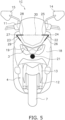
- FIG. 5 is a front view of a straddled vehicle 1C according to a second modification. As shown in FIG. 5 , the left light source 22 and the right light source 23 may be provided in the cowl 18.
- the first lower side portion 32 extends from the lower apex portion 31 toward the left apex portion 24 as seen in the vehicle front view.
- the second lower side portion 33 extends from the lower apex portion 31 toward the right light source 23 as seen in the vehicle front view.
- the second lower side portion 33 extends from the lower apex portion 31 toward the right apex portion 27 as seen in the vehicle front view.
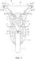
- FIG. 7 is a front view of a straddled vehicle 1E according to a fourth modification.
- the lower light source 21 may be provided on the front fender 13.
- the lower light source 21 may be provided separately from the headlight 19 of the headlight unit 3.
- the left light source 22 and the right light source 23 are not limited to the V-shaped bent shapes as in the above embodiment, but may have other shapes.
- FIG. 8 is a front view of a straddled vehicle 1F according to a fifth modification. As shown in FIG. 8 , the left light source 22 and the right light source 23 may be fan-shaped. The lower light source 21 may also be fan-shaped. Alternatively, the left light source 22, the right light source 23, and the lower light source 21 may have other shapes including V-shaped notches.
- FIG. 9 is a front view of a straddled vehicle 1G according to a sixth modification.
- the subjective contour 30 created by the optical illusion may be a rectangle.
- the straddled vehicle 1A may include a first lower light source 21A and a second lower light source 21B.
- the first lower light source 21A, the second lower light source 21B, the left light source 22, and the right light source 23 are disposed at the apexes of the rectangle connecting the first lower light source 21A, the second lower light source 21B, the left light source 22, and the right light source 23.
- the first lower light source 21A, the second lower light source 21B, the left light source 22, and the right light source 23 constitute each corner of the rectangle connecting the first lower light source 21A, the second lower light source 21B, the left light source 22, and the right light source 23.
- the configurations of the lower light source 21, the left light source 22, and the right light source 23 are not limited to those in the embodiment described above, and may be modified.
- the left light source 22 and the right light source 23 are not limited to position lights, and may be made of reflective material.
- the lower light source 21 is not limited to a headlight, but may be a position light.
- the lower light source 21 may be made of a reflective material.
Landscapes
- Engineering & Computer Science (AREA)
- Mechanical Engineering (AREA)
- Non-Portable Lighting Devices Or Systems Thereof (AREA)
- Lighting Device Outwards From Vehicle And Optical Signal (AREA)
Abstract
Description
- The present invention relates to a straddled vehicle.
- A straddled vehicle is equipped with a light source such as a position light or a headlight. For example, in the motorcycle disclosed in
Japanese Patent Application Publication No. 2011-057104 - Straddled vehicles require improved visibility. By increasing the size of the light source such as the above-mentioned position light or by increasing the number of light sources, the visibility of the straddled vehicle can be improved. However, in that case, the size of the vehicle increases or the weight of the vehicle increases. An object of the present invention is to improve visibility in a straddled vehicle while suppressing the need to increase the size or add a light source.
- A straddled vehicle according to one aspect of the present invention includes a lower light source, a left light source, and a right light source. The left light source is disposed above the lower light source as seen in a vehicle front view. The right light source is disposed above the lower light source as seen in the vehicle front view, and is disposed away from the left light source in a left-right direction of the vehicle. The lower light source, the left light source, and the right light source emit light at the same time. The left light source includes a left apex portion, a first left side portion, and a second left side portion. The first left side portion extends from the left apex portion toward a vehicle center in the left-right direction of the vehicle as seen in the vehicle front view. The second left side portion extends from the left apex portion in a direction forming a predetermined angle with respect to the first left side portion as seen in the vehicle front view. The right light source includes a right apex portion, a first right side portion, and a second right side portion. The first right side portion extends from the right apex portion toward the vehicle center in the left-right direction of the vehicle as seen in the vehicle front view. The second right side portion extends from the right apex portion in a direction forming a predetermined angle with respect to the first right side portion as seen in the vehicle front view.
- In the straddled vehicle according to the present aspect, the shape of the left light source and the right light source as described above allows a viewer to perceive a subjective contour due to an optical illusion. This subjective contour allows the viewer to perceive a larger shape than each of the lower, left, and right light sources. This improves the visibility of the vehicle while suppressing the need to increase the size and addition of light sources.
- As seen in the vehicle front view, the second left side portion may extend toward the lower light source. In this case, the lower light source, the left light source, and the right light source improve the effect of making the viewer perceive a large shape based on the subjective contour.
- As seen in the vehicle front view, the second right side portion may extend toward the lower light source. In this case, the lower light source, the left light source, and the right light source improve the effect of making the viewer perceive a large shape based on the subjective contour.
- The lower light source, the left light source, and the right light source may be respectively disposed at three apexes of an inverted triangle as seen in the vehicle front view. In this case, the lower light source, the left light source, and the right light source improve the effect of making the viewer perceive a large inverted triangle based on the subjective contour.
- The left light source and the right light source may each constitute a corner of the inverted triangle. In this case, the lower light source, the left light source, and the right light source cause the viewer to perceive a large inverted triangle based on the subjective contour.
- The straddled vehicle may further include a left mirror and a right mirror. The left mirror and the right mirror may be disposed apart from each other in the left-right direction of the vehicle. The left light source may be provided on the left mirror. The right light source may be provided on the right mirror. In this case, the left light source and the right light source are disposed with a large distance left and right. This allows the viewer to perceive a larger shape based on the subjective contour.
- The left light source and the right light source may be position lights. In this case, the visibility of the position light is improved.
- The left light source and the right light source may be made of reflective material. In this case, the degree of freedom in arranging the left light source and the right light source is improved.
- The lower light source may be a headlight. In this case, the visibility of the headlight is improved.
- The straddled vehicle may further include a cowl. The lower light source may be provided on the cowl. In this case, the degree of freedom in arranging the lower light source is improved.
- The straddled vehicle may further include a front fender. The lower light source may be provided on the front fender. In this case, the degree of freedom in arranging the lower light source is improved.
- According to the present invention, in a straddled vehicle, visibility is improved while suppressing the need to increase the size or addition of a light source.
-
-
FIG. 1 is a side view of a straddled vehicle according to an embodiment. -
FIG. 2 is a front view of the straddled vehicle. -
FIG. 3 is a front view of the straddled vehicle when the lower light source, the left light source, and the right light source are turned on. -
FIG. 4 is a front view of a straddled vehicle according to a first modification. -
FIG. 5 is a front view of a straddled vehicle according to a second modification. -
FIG. 6 is a front view of a straddled vehicle according to a third modification. -
FIG. 7 is a front view of a straddled vehicle according to a fourth modification. -
FIG. 8 is a front view of a straddled vehicle according to a fifth modification. -
FIG. 9 is a front view of a straddled vehicle according to a sixth modification. - Hereinafter, a straddled vehicle according to an embodiment will be described with reference to the drawings.
FIG. 1 is a side view of a straddledvehicle 1A according to an embodiment.FIG. 2 is a front view of the straddledvehicle 1A. In this embodiment, the straddledvehicle 1A is a street-type motorcycle. As shown inFIGS. 1 and2 , the straddledvehicle 1A includes avehicle body 2 and aheadlight unit 3. Thevehicle body 2 includes asteering device 4, aseat 5, apower unit 6, afront wheel 7, and arear wheel 8. Note that in the following description, the left and right directions mean the left and right directions as seen from a rider seated on theseat 5. - The
steering device 4 includes ahandle 11 and afront fork 12. Thehandle 11 is connected to thefront fork 12. Thehandle 11 is operable left and right by the rider. Thefront fork 12 rotatably supports thefront wheel 7. Afront fender 13 is disposed above thefront wheel 7. - A
left mirror 14 and aright mirror 15 are attached to thehandle 11. Theleft mirror 14 and theright mirror 15 are disposed apart from each other in the left-right direction of the vehicle. Theleft mirror 14 and theright mirror 15 each extend upward from thehandle 11 and outward in the left-right direction of the vehicle as seen in the vehicle front view. - The
seat 5 is disposed behind thesteering device 4. Thepower unit 6 is disposed below theseat 5. Thepower unit 6 includes, for example, an internal combustion engine and a transmission. Alternatively, thepower unit 6 may include an electric motor. Therear wheel 8 is disposed behind thepower unit 6. Theheadlight unit 3 is disposed in front of thefront fork 12. - As shown in
FIG. 2 , the straddledvehicle 1A includes aleft flasher 16 and aright flasher 17. Theleft flasher 16 and theright flasher 17 are attached to thevehicle body 2. Alternatively, theleft flasher 16 and theright flasher 17 may be attached to theheadlight unit 3. - The straddled
vehicle 1A includes a lowerlight source 21, a leftlight source 22, and a rightlight source 23. The lowerlight source 21 is a headlight. The leftlight source 22 and the rightlight source 23 are position lights. The lowerlight source 21, the leftlight source 22, and the rightlight source 23 are configured to emit light at the same time. The lowerlight source 21, the leftlight source 22, and the rightlight source 23 are always turned on while the straddledvehicle 1A is traveling. - The lower
light source 21 is attached to theheadlight unit 3. The lowerlight source 21 is disposed below thehandle 11 as seen in the vehicle front view. The lowerlight source 21 includes, for example, an LED. Alternatively, the lowerlight source 21 may include a bulb. The lowerlight source 21 is disposed at the center of the straddledvehicle 1A in the left-right direction as seen in the vehicle front view. - The left
light source 22 is disposed above the lowerlight source 21 as seen in the vehicle front view. The leftlight source 22 is disposed above thehandle 11 as seen in the vehicle front view. The leftlight source 22 is disposed leftward of the lowerlight source 21 as seen in the vehicle front view. The leftlight source 22 is disposed outside theheadlight unit 3 in the left-right direction of the vehicle as seen in the vehicle front view. The leftlight source 22 is disposed leftward of theheadlight unit 3 as seen in the vehicle front view. - The right
light source 23 is disposed apart from the leftlight source 22 in the left-right direction of the vehicle as seen in the vehicle front view. The rightlight source 23 is disposed above the lowerlight source 21 as seen in the vehicle front view. The rightlight source 23 is disposed above thehandle 11 as seen in the vehicle front view. The rightlight source 23 is disposed rightward of the lowerlight source 21 as seen in the vehicle front view. The rightlight source 23 is disposed outside theheadlight unit 3 in the left-right direction of the vehicle as seen in the vehicle front view. The rightlight source 23 is disposed rightward of theheadlight unit 3 as seen in the vehicle front view. - The lower
light source 21, the leftlight source 22, and the rightlight source 23 are respectively disposed at three apexes of an inverted triangle as seen in the vehicle front view. The leftlight source 22 is provided on a front surface of theleft mirror 14. The rightlight source 23 is provided on a front surface of theright mirror 15. The leftlight source 22 and the rightlight source 23 include, for example, LEDs. Alternatively, the leftlight source 22 and the rightlight source 23 may include bulbs. - The left
light source 22 has a V-shaped bent shape. The leftlight source 22 constitutes the left corner of the inverted triangle connecting the leftlight source 22, the rightlight source 23, and the lowerlight source 21. The leftlight source 22 includes aleft apex portion 24, a firstleft side portion 25, and a secondleft side portion 26. Theleft apex portion 24 is located at the left apex of the inverted triangle connecting the leftlight source 22, the rightlight source 23, and the lowerlight source 21. - The first
left side portion 25 extends from theleft apex portion 24 toward the vehicle center in the left-right direction of the vehicle as seen in the vehicle front view. The firstleft side portion 25 extends rightward from theleft apex portion 24 as seen in the vehicle front view. The firstleft side portion 25 extends from theleft apex portion 24 toward the rightlight source 23 as seen in the vehicle front view. - The second
left side portion 26 extends from theleft apex portion 24 in a direction forming a predetermined angle with respect to the firstleft side portion 25 as seen in the vehicle front view. The predetermined angle is an acute angle. The secondleft side portion 26 extends from theleft apex portion 24 toward the lowerlight source 21 as seen in the vehicle front view. The predetermined angle is an angle of the left corner of the inverted triangle connecting the leftlight source 22, the rightlight source 23, and the lowerlight source 21. - The right
light source 23 is laterally symmetrical to the leftlight source 22 and has a V-shaped bent shape. The rightlight source 23 constitutes the right corner of the inverted triangle connecting the leftlight source 22, the rightlight source 23, and the lowerlight source 21. The rightlight source 23 includes aright apex portion 27, a firstright side portion 28, and a secondright side portion 29. Theright apex portion 27 is located at the right apex of the inverted triangle connecting the leftlight source 22, the rightlight source 23, and the lowerlight source 21. - The first
right side portion 28 extends from theright apex portion 27 toward the vehicle center in the left-right direction of the vehicle as seen in the vehicle front view. The firstright side portion 28 extends leftward from theright apex portion 27 as seen in the vehicle front view. The firstright side portion 28 extends from theright apex portion 27 toward the leftlight source 22 as seen in the vehicle front view. Specifically, the firstright side portion 28 extends from theright apex portion 27 toward theleft apex portion 24 as seen in the vehicle front view. The firstleft side portion 25 described above extends from theleft apex portion 24 toward theright apex portion 27 as seen in the vehicle front view. - The second
right side portion 29 extends from theright apex portion 27 in a direction forming a predetermined angle with respect to the firstright side portion 28 as seen in the vehicle front view. The predetermined angle is an acute angle. The secondright side portion 29 extends from theright apex portion 27 toward the lowerlight source 21 as seen in the vehicle front view. The predetermined angle is an angle of the right corner of the inverted triangle connecting the leftlight source 22, the rightlight source 23, and the lowerlight source 21. -
FIG. 3 is a front view of the straddledvehicle 1A when the lowerlight source 21, the leftlight source 22, and the rightlight source 23 are turned on. As shown inFIG. 3 , in the straddledvehicle 1A according to the present embodiment, thesubjective contour 30 of the inverted triangle created by an optical illusion (so-called Kanizsa's triangle) is perceived by a viewer by the arrangement and the shape of the leftlight source 22, the rightlight source 23, and the lowerlight source 21 as described above. Thissubjective contour 30 allows the viewer to perceive a larger shape than each of the lowerlight source 21, the leftlight source 22, and the rightlight source 23. This improves the visibility of the vehicle while suppressing the need to increase the size and addition of light sources. - Although one embodiment of the present invention has been described above, the present invention is not limited to the above embodiment, and various changes can be made without departing from the gist of the invention.
- The straddled vehicle is not limited to a street-type motorcycle. The straddled vehicle may be another type of vehicle such as a sports-type motorcycle, a scooter, or a moped.
- The arrangement of the lower
light source 21 is not limited to that of the above embodiment, and may be changed. For example,FIG. 4 is a front view of a straddled vehicle 1B according to a first modification. As shown inFIG. 4 , the straddled vehicle 1B may include acowl 18. The lowerlight source 21 may be provided on thecowl 18. The lowerlight source 21 may be provided separately from theheadlight 19 of theheadlight unit 3. - The arrangement of the left
light source 22 and the rightlight source 23 is not limited to that of the above embodiment, and may be changed. For example,FIG. 5 is a front view of a straddledvehicle 1C according to a second modification. As shown inFIG. 5 , the leftlight source 22 and the rightlight source 23 may be provided in thecowl 18. - The shape of the lower
light source 21 is not limited to that of the above embodiment, and may be changed. For example,FIG. 6 is a front view of a straddledvehicle 1D according to a third modification. As shown inFIG. 6 , the lowerlight source 21 may have a V-shaped bent shape. That is, the lowerlight source 21 may include alower apex portion 31, a firstlower side portion 32, and a secondlower side portion 33. Thelower apex portion 31 is located at the lower apex of the inverted triangle connecting the leftlight source 22, the rightlight source 23, and the lowerlight source 21. The firstlower side portion 32 extends from thelower apex portion 31 toward the leftlight source 22 as seen in the vehicle front view. The firstlower side portion 32 extends from thelower apex portion 31 toward theleft apex portion 24 as seen in the vehicle front view. The secondlower side portion 33 extends from thelower apex portion 31 toward the rightlight source 23 as seen in the vehicle front view. The secondlower side portion 33 extends from thelower apex portion 31 toward theright apex portion 27 as seen in the vehicle front view. -
FIG. 7 is a front view of a straddledvehicle 1E according to a fourth modification. As shown inFIG. 7 , the lowerlight source 21 may be provided on thefront fender 13. The lowerlight source 21 may be provided separately from theheadlight 19 of theheadlight unit 3. - The left
light source 22 and the rightlight source 23 are not limited to the V-shaped bent shapes as in the above embodiment, but may have other shapes. For example,FIG. 8 is a front view of a straddledvehicle 1F according to a fifth modification. As shown inFIG. 8 , the leftlight source 22 and the rightlight source 23 may be fan-shaped. The lowerlight source 21 may also be fan-shaped. Alternatively, the leftlight source 22, the rightlight source 23, and the lowerlight source 21 may have other shapes including V-shaped notches. - The
subjective contour 30 created by the optical illusion is not limited to an inverted triangle, but may have other shapes. For example,FIG. 9 is a front view of a straddledvehicle 1G according to a sixth modification. As shown inFIG. 9 , thesubjective contour 30 created by the optical illusion may be a rectangle. In this case, the straddledvehicle 1A may include a first lowerlight source 21A and a second lowerlight source 21B. The first lowerlight source 21A, the second lowerlight source 21B, the leftlight source 22, and the rightlight source 23 are disposed at the apexes of the rectangle connecting the first lowerlight source 21A, the second lowerlight source 21B, the leftlight source 22, and the rightlight source 23. The first lowerlight source 21A, the second lowerlight source 21B, the leftlight source 22, and the rightlight source 23 constitute each corner of the rectangle connecting the first lowerlight source 21A, the second lowerlight source 21B, the leftlight source 22, and the rightlight source 23. - The configurations of the lower
light source 21, the leftlight source 22, and the rightlight source 23 are not limited to those in the embodiment described above, and may be modified. For example, the leftlight source 22 and the rightlight source 23 are not limited to position lights, and may be made of reflective material. The lowerlight source 21 is not limited to a headlight, but may be a position light. The lowerlight source 21 may be made of a reflective material. - 13: Front fender, 14: Left mirror, 15: Right mirror, 18: Cowl, 21: Lower light source, 22: Left light source, 23: Right light source, 24: Left apex portion, 25: First left side portion, 26: Second left side portion, 27: Right apex portion, 28: First right side portion, 29: Second right side portion
Claims (11)
- A straddled vehicle (1A) comprising:a lower light source (21);a left light source (22) disposed above the lower light source (21) as seen in a vehicle front view; anda right light source (23) disposed above the lower light source (21) and disposed apart from the left light source (22) in a left-right direction of the vehicle as seen in the vehicle front view, whereinthe lower light source (21), the left light source (22), and the right light source (23) are configured to emit light at the same time,the left light source (22) including:a left apex portion (24),a first left side portion (25) extending from the left apex portion (24) toward a vehicle center in the left-right direction of the vehicle as seen in the vehicle front view, anda second left side portion (26) extending from the left apex portion (24) in a direction forming a predetermined angle with respect to the first left side portion (25) as seen in the vehicle front view, andthe right light source (23) including:a right apex portion (27),a first right side portion (28) extending from the right apex portion (27) toward the vehicle center in the left-right direction of the vehicle as seen in the vehicle front view, anda second right side portion (29) extending from the right apex portion (27) in a direction forming a predetermined angle with respect to the first right side portion (28) as seen in the vehicle front view.
- The straddled vehicle according to claim 1, wherein
the second left side portion (26) extends toward the lower light source (21) as seen in the vehicle front view. - The straddled vehicle according to claim 1 or 2, wherein
the second right side portion (29) extends toward the lower light source (21) as seen in the vehicle front view. - The straddled vehicle according to any one of claims 1 to 3, wherein
the lower light source (21), the left light source (22), and the right light source (23) are respectively disposed at three apexes of an inverted triangle as seen in the vehicle front view. - The straddled vehicle according to claim 4, wherein
the left light source (22) and the right light source (23) each constitute a corner of the inverted triangle. - The straddled vehicle according to any one of claims 1 to 5, further comprising a left mirror (14) and a right mirror (15) disposed apart from each other in the left-right direction of the vehicle, whereinthe left light source (22) is provided on the left mirror, andthe right light source (23) is provided on the right mirror.
- The straddled vehicle according to any one of claims 1 to 6, wherein
the left light source (22) and the right light source (23) are position lights. - The straddled vehicle according to any one of claims 1 to 6, wherein
the left light source (22) and the right light source (23) are made of reflective materials. - The straddled vehicle according to any one of claims 1 to 8, wherein
the lower light source (21) is a headlight. - The straddled vehicle according to any one of claims 1 to 9, further comprising a cowl, wherein
the lower light source (21) is provided on the cowl (18). - The straddled vehicle according to any one of claims 1 to 9, further comprising a front fender (13), wherein
the lower light source (21) is provided on the front fender (13).
Applications Claiming Priority (1)
| Application Number | Priority Date | Filing Date | Title |
|---|---|---|---|
| JP2023149823A JP7807417B2 (en) | 2023-09-15 | 2023-09-15 | Saddle-type vehicle |
Publications (1)
| Publication Number | Publication Date |
|---|---|
| EP4524008A1 true EP4524008A1 (en) | 2025-03-19 |
Family
ID=90880730
Family Applications (1)
| Application Number | Title | Priority Date | Filing Date |
|---|---|---|---|
| EP24172094.5A Pending EP4524008A1 (en) | 2023-09-15 | 2024-04-24 | Straddled vehicle |
Country Status (2)
| Country | Link |
|---|---|
| EP (1) | EP4524008A1 (en) |
| JP (1) | JP7807417B2 (en) |
Citations (2)
| Publication number | Priority date | Publication date | Assignee | Title |
|---|---|---|---|---|
| JP2011057104A (en) | 2009-09-10 | 2011-03-24 | Honda Motor Co Ltd | Motorcycle |
| EP3560805A1 (en) * | 2018-04-25 | 2019-10-30 | Yamaha Hatsudoki Kabushiki Kaisha | Straddled vehicle |
Family Cites Families (4)
| Publication number | Priority date | Publication date | Assignee | Title |
|---|---|---|---|---|
| JPH02132536U (en) * | 1989-04-10 | 1990-11-02 | ||
| JP2003300488A (en) * | 2002-02-05 | 2003-10-21 | Honda Motor Co Ltd | Lighting arrangement of motorcycles |
| US10118544B1 (en) * | 2017-11-15 | 2018-11-06 | Wei-Tai Lin | Brake warning light |
| WO2021199067A1 (en) * | 2020-03-31 | 2021-10-07 | Tvs Motor Company Limited | Cowl assembly of a saddle type vehicle |
-
2023
- 2023-09-15 JP JP2023149823A patent/JP7807417B2/en active Active
-
2024
- 2024-04-24 EP EP24172094.5A patent/EP4524008A1/en active Pending
Patent Citations (2)
| Publication number | Priority date | Publication date | Assignee | Title |
|---|---|---|---|---|
| JP2011057104A (en) | 2009-09-10 | 2011-03-24 | Honda Motor Co Ltd | Motorcycle |
| EP3560805A1 (en) * | 2018-04-25 | 2019-10-30 | Yamaha Hatsudoki Kabushiki Kaisha | Straddled vehicle |
Non-Patent Citations (1)
| Title |
|---|
| KIWAV.COM: "motorcycle mirrors Lucifer Two-tone color LED lights - KiWAV", 23 June 2016 (2016-06-23), XP093206274, Retrieved from the Internet <URL:https://www.youtube.com/watch?app=desktop&v=PEJy6ihWFBQ> [retrieved on 20240918] * |
Also Published As
| Publication number | Publication date |
|---|---|
| JP7807417B2 (en) | 2026-01-27 |
| JP2025042723A (en) | 2025-03-28 |
Similar Documents
| Publication | Publication Date | Title |
|---|---|---|
| US9593817B2 (en) | Headlight device of motorcycle | |
| CN105593060B (en) | For modulated structure before the LED of motorcycle | |
| EP1908629B1 (en) | Headlight device and vehicle | |
| US10391925B2 (en) | Vehicle headlight with a plurality of inner non spherical lenses transmitting light from a high beam and a low beam light source | |
| JP6975844B2 (en) | Cornering lights for saddle-mounted vehicles | |
| EP3115286B1 (en) | Straddled vehicle | |
| CN107429893A (en) | Headlamp | |
| JP3878652B2 (en) | Saddle riding vehicle | |
| JP5207871B2 (en) | Lighting device integrated rearview mirror | |
| JP4630780B2 (en) | Arrangement structure of scooter type vehicles | |
| JP2009181913A (en) | Vehicle headlamp device | |
| JP2004322827A (en) | Combination lamp | |
| JP5624200B2 (en) | Vehicle headlamp device | |
| EP3560805B1 (en) | Straddled vehicle | |
| JP6850897B2 (en) | vehicle | |
| JP7807417B2 (en) | Saddle-type vehicle | |
| JP6236047B2 (en) | Vehicle rear combination lamp and vehicle | |
| JP6975843B2 (en) | Cornering lights for saddle-mounted vehicles | |
| JP6426577B2 (en) | Rear combination lamp for vehicle and vehicle | |
| EP3885193B1 (en) | Straddled vehicle | |
| JP2015123786A (en) | Front structure in motor cycle | |
| CN100572895C (en) | Structure of lamps for vehicles | |
| JP2022070603A (en) | Lighting structure | |
| TWI413599B (en) | Saddle type vehicle | |
| JP4376728B2 (en) | Motorcycle lights |
Legal Events
| Date | Code | Title | Description |
|---|---|---|---|
| PUAI | Public reference made under article 153(3) epc to a published international application that has entered the european phase |
Free format text: ORIGINAL CODE: 0009012 |
|
| STAA | Information on the status of an ep patent application or granted ep patent |
Free format text: STATUS: REQUEST FOR EXAMINATION WAS MADE |
|
| 17P | Request for examination filed |
Effective date: 20240424 |
|
| AK | Designated contracting states |
Kind code of ref document: A1 Designated state(s): AL AT BE BG CH CY CZ DE DK EE ES FI FR GB GR HR HU IE IS IT LI LT LU LV MC ME MK MT NL NO PL PT RO RS SE SI SK SM TR |
|
| P01 | Opt-out of the competence of the unified patent court (upc) registered |
Free format text: CASE NUMBER: APP_17089/2025 Effective date: 20250408 |
|
| STAA | Information on the status of an ep patent application or granted ep patent |
Free format text: STATUS: EXAMINATION IS IN PROGRESS |
|
| 17Q | First examination report despatched |
Effective date: 20250527 |