EP4523892A1 - Heating device - Google Patents
Heating device Download PDFInfo
- Publication number
- EP4523892A1 EP4523892A1 EP24194513.8A EP24194513A EP4523892A1 EP 4523892 A1 EP4523892 A1 EP 4523892A1 EP 24194513 A EP24194513 A EP 24194513A EP 4523892 A1 EP4523892 A1 EP 4523892A1
- Authority
- EP
- European Patent Office
- Prior art keywords
- heat transfer
- transfer body
- insulator
- heat
- heating device
- Prior art date
- Legal status (The legal status is an assumption and is not a legal conclusion. Google has not performed a legal analysis and makes no representation as to the accuracy of the status listed.)
- Pending
Links
Images


Classifications
-
- H—ELECTRICITY
- H05—ELECTRIC TECHNIQUES NOT OTHERWISE PROVIDED FOR
- H05B—ELECTRIC HEATING; ELECTRIC LIGHT SOURCES NOT OTHERWISE PROVIDED FOR; CIRCUIT ARRANGEMENTS FOR ELECTRIC LIGHT SOURCES, IN GENERAL
- H05B3/00—Ohmic-resistance heating
- H05B3/20—Heating elements having extended surface area substantially in a two-dimensional [2D] plane, e.g. plate-heater
- H05B3/22—Heating elements having extended surface area substantially in a two-dimensional [2D] plane, e.g. plate-heater non-flexible
- H05B3/26—Heating elements having extended surface area substantially in a two-dimensional [2D] plane, e.g. plate-heater non-flexible heating conductor mounted on insulating base
- H05B3/262—Heating elements having extended surface area substantially in a two-dimensional [2D] plane, e.g. plate-heater non-flexible heating conductor mounted on insulating base the insulating base being an insulated metal plate
-
- B—PERFORMING OPERATIONS; TRANSPORTING
- B29—WORKING OF PLASTICS; WORKING OF SUBSTANCES IN A PLASTIC STATE IN GENERAL
- B29C—SHAPING OR JOINING OF PLASTICS; SHAPING OF MATERIAL IN A PLASTIC STATE, NOT OTHERWISE PROVIDED FOR; AFTER-TREATMENT OF THE SHAPED PRODUCTS, e.g. REPAIRING
- B29C65/00—Joining or sealing of preformed parts, e.g. welding of plastics materials; Apparatus therefor
- B29C65/02—Joining or sealing of preformed parts, e.g. welding of plastics materials; Apparatus therefor by heating, with or without pressure
- B29C65/18—Joining or sealing of preformed parts, e.g. welding of plastics materials; Apparatus therefor by heating, with or without pressure using heated tools
-
- B—PERFORMING OPERATIONS; TRANSPORTING
- B29—WORKING OF PLASTICS; WORKING OF SUBSTANCES IN A PLASTIC STATE IN GENERAL
- B29C—SHAPING OR JOINING OF PLASTICS; SHAPING OF MATERIAL IN A PLASTIC STATE, NOT OTHERWISE PROVIDED FOR; AFTER-TREATMENT OF THE SHAPED PRODUCTS, e.g. REPAIRING
- B29C65/00—Joining or sealing of preformed parts, e.g. welding of plastics materials; Apparatus therefor
- B29C65/02—Joining or sealing of preformed parts, e.g. welding of plastics materials; Apparatus therefor by heating, with or without pressure
- B29C65/18—Joining or sealing of preformed parts, e.g. welding of plastics materials; Apparatus therefor by heating, with or without pressure using heated tools
- B29C65/24—Joining or sealing of preformed parts, e.g. welding of plastics materials; Apparatus therefor by heating, with or without pressure using heated tools characterised by the means for heating the tool
- B29C65/30—Electrical means
-
- B—PERFORMING OPERATIONS; TRANSPORTING
- B29—WORKING OF PLASTICS; WORKING OF SUBSTANCES IN A PLASTIC STATE IN GENERAL
- B29C—SHAPING OR JOINING OF PLASTICS; SHAPING OF MATERIAL IN A PLASTIC STATE, NOT OTHERWISE PROVIDED FOR; AFTER-TREATMENT OF THE SHAPED PRODUCTS, e.g. REPAIRING
- B29C66/00—General aspects of processes or apparatus for joining preformed parts
- B29C66/01—General aspects dealing with the joint area or with the area to be joined
- B29C66/05—Particular design of joint configurations
- B29C66/10—Particular design of joint configurations particular design of the joint cross-sections
- B29C66/11—Joint cross-sections comprising a single joint-segment, i.e. one of the parts to be joined comprising a single joint-segment in the joint cross-section
- B29C66/112—Single lapped joints
- B29C66/1122—Single lap to lap joints, i.e. overlap joints
-
- B—PERFORMING OPERATIONS; TRANSPORTING
- B29—WORKING OF PLASTICS; WORKING OF SUBSTANCES IN A PLASTIC STATE IN GENERAL
- B29C—SHAPING OR JOINING OF PLASTICS; SHAPING OF MATERIAL IN A PLASTIC STATE, NOT OTHERWISE PROVIDED FOR; AFTER-TREATMENT OF THE SHAPED PRODUCTS, e.g. REPAIRING
- B29C66/00—General aspects of processes or apparatus for joining preformed parts
- B29C66/40—General aspects of joining substantially flat articles, e.g. plates, sheets or web-like materials; Making flat seams in tubular or hollow articles; Joining single elements to substantially flat surfaces
- B29C66/41—Joining substantially flat articles ; Making flat seams in tubular or hollow articles
- B29C66/45—Joining of substantially the whole surface of the articles
-
- B—PERFORMING OPERATIONS; TRANSPORTING
- B29—WORKING OF PLASTICS; WORKING OF SUBSTANCES IN A PLASTIC STATE IN GENERAL
- B29C—SHAPING OR JOINING OF PLASTICS; SHAPING OF MATERIAL IN A PLASTIC STATE, NOT OTHERWISE PROVIDED FOR; AFTER-TREATMENT OF THE SHAPED PRODUCTS, e.g. REPAIRING
- B29C66/00—General aspects of processes or apparatus for joining preformed parts
- B29C66/70—General aspects of processes or apparatus for joining preformed parts characterised by the composition, physical properties or the structure of the material of the parts to be joined; Joining with non-plastics material
- B29C66/73—General aspects of processes or apparatus for joining preformed parts characterised by the composition, physical properties or the structure of the material of the parts to be joined; Joining with non-plastics material characterised by the intensive physical properties of the material of the parts to be joined, by the optical properties of the material of the parts to be joined, by the extensive physical properties of the parts to be joined, by the state of the material of the parts to be joined or by the material of the parts to be joined being a thermoplastic or a thermoset
- B29C66/739—General aspects of processes or apparatus for joining preformed parts characterised by the composition, physical properties or the structure of the material of the parts to be joined; Joining with non-plastics material characterised by the intensive physical properties of the material of the parts to be joined, by the optical properties of the material of the parts to be joined, by the extensive physical properties of the parts to be joined, by the state of the material of the parts to be joined or by the material of the parts to be joined being a thermoplastic or a thermoset characterised by the material of the parts to be joined being a thermoplastic or a thermoset
- B29C66/7392—General aspects of processes or apparatus for joining preformed parts characterised by the composition, physical properties or the structure of the material of the parts to be joined; Joining with non-plastics material characterised by the intensive physical properties of the material of the parts to be joined, by the optical properties of the material of the parts to be joined, by the extensive physical properties of the parts to be joined, by the state of the material of the parts to be joined or by the material of the parts to be joined being a thermoplastic or a thermoset characterised by the material of the parts to be joined being a thermoplastic or a thermoset characterised by the material of at least one of the parts being a thermoplastic
- B29C66/73921—General aspects of processes or apparatus for joining preformed parts characterised by the composition, physical properties or the structure of the material of the parts to be joined; Joining with non-plastics material characterised by the intensive physical properties of the material of the parts to be joined, by the optical properties of the material of the parts to be joined, by the extensive physical properties of the parts to be joined, by the state of the material of the parts to be joined or by the material of the parts to be joined being a thermoplastic or a thermoset characterised by the material of the parts to be joined being a thermoplastic or a thermoset characterised by the material of at least one of the parts being a thermoplastic characterised by the materials of both parts being thermoplastics
-
- B—PERFORMING OPERATIONS; TRANSPORTING
- B29—WORKING OF PLASTICS; WORKING OF SUBSTANCES IN A PLASTIC STATE IN GENERAL
- B29C—SHAPING OR JOINING OF PLASTICS; SHAPING OF MATERIAL IN A PLASTIC STATE, NOT OTHERWISE PROVIDED FOR; AFTER-TREATMENT OF THE SHAPED PRODUCTS, e.g. REPAIRING
- B29C66/00—General aspects of processes or apparatus for joining preformed parts
- B29C66/80—General aspects of machine operations or constructions and parts thereof
- B29C66/81—General aspects of the pressing elements, i.e. the elements applying pressure on the parts to be joined in the area to be joined, e.g. the welding jaws or clamps
- B29C66/812—General aspects of the pressing elements, i.e. the elements applying pressure on the parts to be joined in the area to be joined, e.g. the welding jaws or clamps characterised by the composition, by the structure, by the intensive physical properties or by the optical properties of the material constituting the pressing elements, e.g. constituting the welding jaws or clamps
- B29C66/8122—General aspects of the pressing elements, i.e. the elements applying pressure on the parts to be joined in the area to be joined, e.g. the welding jaws or clamps characterised by the composition, by the structure, by the intensive physical properties or by the optical properties of the material constituting the pressing elements, e.g. constituting the welding jaws or clamps characterised by the composition of the material constituting the pressing elements, e.g. constituting the welding jaws or clamps
-
- B—PERFORMING OPERATIONS; TRANSPORTING
- B29—WORKING OF PLASTICS; WORKING OF SUBSTANCES IN A PLASTIC STATE IN GENERAL
- B29C—SHAPING OR JOINING OF PLASTICS; SHAPING OF MATERIAL IN A PLASTIC STATE, NOT OTHERWISE PROVIDED FOR; AFTER-TREATMENT OF THE SHAPED PRODUCTS, e.g. REPAIRING
- B29C66/00—General aspects of processes or apparatus for joining preformed parts
- B29C66/80—General aspects of machine operations or constructions and parts thereof
- B29C66/81—General aspects of the pressing elements, i.e. the elements applying pressure on the parts to be joined in the area to be joined, e.g. the welding jaws or clamps
- B29C66/818—General aspects of the pressing elements, i.e. the elements applying pressure on the parts to be joined in the area to be joined, e.g. the welding jaws or clamps characterised by the cooling constructional aspects, or by the thermal or electrical insulating or conducting constructional aspects of the welding jaws or of the clamps ; comprising means for compensating for the thermal expansion of the welding jaws or of the clamps
- B29C66/8181—General aspects of the pressing elements, i.e. the elements applying pressure on the parts to be joined in the area to be joined, e.g. the welding jaws or clamps characterised by the cooling constructional aspects, or by the thermal or electrical insulating or conducting constructional aspects of the welding jaws or of the clamps ; comprising means for compensating for the thermal expansion of the welding jaws or of the clamps characterised by the cooling constructional aspects
- B29C66/81811—General aspects of the pressing elements, i.e. the elements applying pressure on the parts to be joined in the area to be joined, e.g. the welding jaws or clamps characterised by the cooling constructional aspects, or by the thermal or electrical insulating or conducting constructional aspects of the welding jaws or of the clamps ; comprising means for compensating for the thermal expansion of the welding jaws or of the clamps characterised by the cooling constructional aspects of the welding jaws
-
- B—PERFORMING OPERATIONS; TRANSPORTING
- B29—WORKING OF PLASTICS; WORKING OF SUBSTANCES IN A PLASTIC STATE IN GENERAL
- B29C—SHAPING OR JOINING OF PLASTICS; SHAPING OF MATERIAL IN A PLASTIC STATE, NOT OTHERWISE PROVIDED FOR; AFTER-TREATMENT OF THE SHAPED PRODUCTS, e.g. REPAIRING
- B29C66/00—General aspects of processes or apparatus for joining preformed parts
- B29C66/80—General aspects of machine operations or constructions and parts thereof
- B29C66/81—General aspects of the pressing elements, i.e. the elements applying pressure on the parts to be joined in the area to be joined, e.g. the welding jaws or clamps
- B29C66/818—General aspects of the pressing elements, i.e. the elements applying pressure on the parts to be joined in the area to be joined, e.g. the welding jaws or clamps characterised by the cooling constructional aspects, or by the thermal or electrical insulating or conducting constructional aspects of the welding jaws or of the clamps ; comprising means for compensating for the thermal expansion of the welding jaws or of the clamps
- B29C66/8183—General aspects of the pressing elements, i.e. the elements applying pressure on the parts to be joined in the area to be joined, e.g. the welding jaws or clamps characterised by the cooling constructional aspects, or by the thermal or electrical insulating or conducting constructional aspects of the welding jaws or of the clamps ; comprising means for compensating for the thermal expansion of the welding jaws or of the clamps characterised by the thermal conducting constructional aspects
- B29C66/81831—General aspects of the pressing elements, i.e. the elements applying pressure on the parts to be joined in the area to be joined, e.g. the welding jaws or clamps characterised by the cooling constructional aspects, or by the thermal or electrical insulating or conducting constructional aspects of the welding jaws or of the clamps ; comprising means for compensating for the thermal expansion of the welding jaws or of the clamps characterised by the thermal conducting constructional aspects of the welding jaws
-
- B—PERFORMING OPERATIONS; TRANSPORTING
- B29—WORKING OF PLASTICS; WORKING OF SUBSTANCES IN A PLASTIC STATE IN GENERAL
- B29C—SHAPING OR JOINING OF PLASTICS; SHAPING OF MATERIAL IN A PLASTIC STATE, NOT OTHERWISE PROVIDED FOR; AFTER-TREATMENT OF THE SHAPED PRODUCTS, e.g. REPAIRING
- B29C66/00—General aspects of processes or apparatus for joining preformed parts
- B29C66/80—General aspects of machine operations or constructions and parts thereof
- B29C66/81—General aspects of the pressing elements, i.e. the elements applying pressure on the parts to be joined in the area to be joined, e.g. the welding jaws or clamps
- B29C66/818—General aspects of the pressing elements, i.e. the elements applying pressure on the parts to be joined in the area to be joined, e.g. the welding jaws or clamps characterised by the cooling constructional aspects, or by the thermal or electrical insulating or conducting constructional aspects of the welding jaws or of the clamps ; comprising means for compensating for the thermal expansion of the welding jaws or of the clamps
- B29C66/8187—General aspects of the pressing elements, i.e. the elements applying pressure on the parts to be joined in the area to be joined, e.g. the welding jaws or clamps characterised by the cooling constructional aspects, or by the thermal or electrical insulating or conducting constructional aspects of the welding jaws or of the clamps ; comprising means for compensating for the thermal expansion of the welding jaws or of the clamps characterised by the electrical insulating constructional aspects
- B29C66/81871—General aspects of the pressing elements, i.e. the elements applying pressure on the parts to be joined in the area to be joined, e.g. the welding jaws or clamps characterised by the cooling constructional aspects, or by the thermal or electrical insulating or conducting constructional aspects of the welding jaws or of the clamps ; comprising means for compensating for the thermal expansion of the welding jaws or of the clamps characterised by the electrical insulating constructional aspects of the welding jaws
-
- B—PERFORMING OPERATIONS; TRANSPORTING
- B29—WORKING OF PLASTICS; WORKING OF SUBSTANCES IN A PLASTIC STATE IN GENERAL
- B29C—SHAPING OR JOINING OF PLASTICS; SHAPING OF MATERIAL IN A PLASTIC STATE, NOT OTHERWISE PROVIDED FOR; AFTER-TREATMENT OF THE SHAPED PRODUCTS, e.g. REPAIRING
- B29C66/00—General aspects of processes or apparatus for joining preformed parts
- B29C66/80—General aspects of machine operations or constructions and parts thereof
- B29C66/81—General aspects of the pressing elements, i.e. the elements applying pressure on the parts to be joined in the area to be joined, e.g. the welding jaws or clamps
- B29C66/818—General aspects of the pressing elements, i.e. the elements applying pressure on the parts to be joined in the area to be joined, e.g. the welding jaws or clamps characterised by the cooling constructional aspects, or by the thermal or electrical insulating or conducting constructional aspects of the welding jaws or of the clamps ; comprising means for compensating for the thermal expansion of the welding jaws or of the clamps
- B29C66/8188—General aspects of the pressing elements, i.e. the elements applying pressure on the parts to be joined in the area to be joined, e.g. the welding jaws or clamps characterised by the cooling constructional aspects, or by the thermal or electrical insulating or conducting constructional aspects of the welding jaws or of the clamps ; comprising means for compensating for the thermal expansion of the welding jaws or of the clamps characterised by the electrical conducting constructional aspects
- B29C66/81881—General aspects of the pressing elements, i.e. the elements applying pressure on the parts to be joined in the area to be joined, e.g. the welding jaws or clamps characterised by the cooling constructional aspects, or by the thermal or electrical insulating or conducting constructional aspects of the welding jaws or of the clamps ; comprising means for compensating for the thermal expansion of the welding jaws or of the clamps characterised by the electrical conducting constructional aspects of the welding jaws
-
- B—PERFORMING OPERATIONS; TRANSPORTING
- B29—WORKING OF PLASTICS; WORKING OF SUBSTANCES IN A PLASTIC STATE IN GENERAL
- B29C—SHAPING OR JOINING OF PLASTICS; SHAPING OF MATERIAL IN A PLASTIC STATE, NOT OTHERWISE PROVIDED FOR; AFTER-TREATMENT OF THE SHAPED PRODUCTS, e.g. REPAIRING
- B29C66/00—General aspects of processes or apparatus for joining preformed parts
- B29C66/80—General aspects of machine operations or constructions and parts thereof
- B29C66/83—General aspects of machine operations or constructions and parts thereof characterised by the movement of the joining or pressing tools
- B29C66/832—Reciprocating joining or pressing tools
- B29C66/8322—Joining or pressing tools reciprocating along one axis
-
- B—PERFORMING OPERATIONS; TRANSPORTING
- B29—WORKING OF PLASTICS; WORKING OF SUBSTANCES IN A PLASTIC STATE IN GENERAL
- B29C—SHAPING OR JOINING OF PLASTICS; SHAPING OF MATERIAL IN A PLASTIC STATE, NOT OTHERWISE PROVIDED FOR; AFTER-TREATMENT OF THE SHAPED PRODUCTS, e.g. REPAIRING
- B29C66/00—General aspects of processes or apparatus for joining preformed parts
- B29C66/80—General aspects of machine operations or constructions and parts thereof
- B29C66/83—General aspects of machine operations or constructions and parts thereof characterised by the movement of the joining or pressing tools
- B29C66/832—Reciprocating joining or pressing tools
- B29C66/8322—Joining or pressing tools reciprocating along one axis
- B29C66/83221—Joining or pressing tools reciprocating along one axis cooperating reciprocating tools, each tool reciprocating along one axis
-
- H—ELECTRICITY
- H05—ELECTRIC TECHNIQUES NOT OTHERWISE PROVIDED FOR
- H05B—ELECTRIC HEATING; ELECTRIC LIGHT SOURCES NOT OTHERWISE PROVIDED FOR; CIRCUIT ARRANGEMENTS FOR ELECTRIC LIGHT SOURCES, IN GENERAL
- H05B3/00—Ohmic-resistance heating
- H05B3/10—Heating elements characterised by the composition or nature of the materials or by the arrangement of the conductor
- H05B3/12—Heating elements characterised by the composition or nature of the materials or by the arrangement of the conductor characterised by the composition or nature of the conductive material
- H05B3/14—Heating elements characterised by the composition or nature of the materials or by the arrangement of the conductor characterised by the composition or nature of the conductive material the material being non-metallic
- H05B3/145—Carbon only, e.g. carbon black, graphite
-
- H—ELECTRICITY
- H05—ELECTRIC TECHNIQUES NOT OTHERWISE PROVIDED FOR
- H05B—ELECTRIC HEATING; ELECTRIC LIGHT SOURCES NOT OTHERWISE PROVIDED FOR; CIRCUIT ARRANGEMENTS FOR ELECTRIC LIGHT SOURCES, IN GENERAL
- H05B3/00—Ohmic-resistance heating
- H05B3/10—Heating elements characterised by the composition or nature of the materials or by the arrangement of the conductor
- H05B3/16—Heating elements characterised by the composition or nature of the materials or by the arrangement of the conductor the conductor being mounted on an insulating base
-
- B—PERFORMING OPERATIONS; TRANSPORTING
- B29—WORKING OF PLASTICS; WORKING OF SUBSTANCES IN A PLASTIC STATE IN GENERAL
- B29L—INDEXING SCHEME ASSOCIATED WITH SUBCLASS B29C, RELATING TO PARTICULAR ARTICLES
- B29L2031/00—Other particular articles
- B29L2031/30—Vehicles, e.g. ships or aircraft, or body parts thereof
- B29L2031/3076—Aircrafts
Definitions
- the present disclosure relates to a heating device suitable for heat-welding thermoplastic composite materials.
- thermoplastic composite materials used as structural materials of an aircraft.
- heat conduction welding is known as a heat welding technique for thermoplastic composite materials used as structural materials of an aircraft.
- a heater is brought into contact with an outer surface of each thermoplastic composite material, heat generated by the heater is transferred to the inside of the material, and pressure is applied while melting a welding interface until the melting point is exceeded.
- a thermoplastic composite material used as a structural material of an aircraft is made of carbon fiber reinforced thermoplastics (CFRTP).
- Patent Document 1 proposes a welding device that can implement efficient welding in terms of time and energy (electric power).
- the welding device of Patent Document 1 has a five-layer structure in which a graphite heater having a sheet- or film-like shape are sandwiched on both front and back surfaces thereof between insulating materials, and the insulating materials on the front and back surfaces are covered with an outer cover and an inner cover, respectively.
- Patent Document 1 JP 7275246 B
- the welding device of Patent Document 1 has the five-layer structure in which the graphite heater is provided, on the front and back surfaces thereof, with the insulating materials, the outer cover, and the inner cover, and thus the insulating materials and the covers are expected to have an effect of preventing oxidative consumption due to bonding between the graphite heater and oxygen in the atmosphere. However, it is desired to further reduce the oxidative consumption.
- an object of the present disclosure is to further reduce oxidative consumption of a heater in a heating device in which the heater having a sheet-like shape is laminated with other members from the front and back sides as in Patent Document 1, for example.
- a heating device includes: a heat generator configured to generate heat when supplied with electric power; a first insulator and a second insulator respectively layered on a front surface and a back surface of the heat generator and each covering the heat generator; a first heat transfer body layered on the first insulator and covering the first insulator and a second heat transfer body layered on the second insulator and covering the second insulator; and a circumferential edge structure configured to seal circumferential edges of the first insulator and the second insulator.
- the circumferential edges are sealed by direct or indirect joining of the first heat transfer body and the second heat transfer body.
- the heating device includes the circumferential edge structure in which the circumferential edges are sealed by direct or indirect joining of the first heat transfer body and the second heat transfer body. Having the circumferential edge structure blocks an entering path of oxygen into the heat generator, allowing the oxidative consumption of the heat generator to be suppressed.
- a heating device 1 according to an embodiment will be described below with reference to the accompanying drawings.
- the heating device 1 is suitably used for joining two members made of carbon fiber reinforced thermoplastic plastics (hereinafter CFRTP) by welding.
- CFRTP carbon fiber reinforced thermoplastic plastics
- the heating device 1 has a multilayer structure in which a heat generator having a sheet-like shape is sandwiched, and a portion which can be an entering path of oxygen in the multilayer structure is sealed.
- the heating device 1 can reduce the oxidative consumption of a heat generator 11 by employing diffusion bonding as a preferred sealing means.
- the heating device 1 is configured by layering the heat generator 11, a pair of a first insulator 13 and a second insulator 14 made of electrically insulating materials respectively layered on the front and back surfaces of the heat generator 11, and a first heat transfer body 17 and a second heat transfer body 18 respectively layered on the first insulator 13 and the second insulator 14.
- the heat generator 11 is a sheet-like heating element that generates heat when supplied with electric power.
- the heat generator is made of graphite, for example, and generates heat when supplied with electric power.
- a graphite heater emits a large amount of infrared radiation, can generate heat in a short time of 1 second or less, and is thus suitable for heat welding of CFRTP.
- the graphite heater is merely a preferred example in the present disclosure.
- a carbon heater using carbon fibers as a heating element a ceramic heater using alumina (Al 2 O 3 ), silica nitride (Si 3 N 4 ), or the like as a heating element, a thin metal film heater, or the like can be used in the present disclosure.
- the outer shape of the heat generator 11 is a rectangle as an example in a plan view, but may have another shape. Note that "rectangle" refers to a quadrangle having four equal corners. In addition, in order to absorb thermal expansion during heating and to increase a laying amount per unit area, it is preferable to employ a zigzag pattern.
- Second Insulator 14 See FIG. 2
- the first insulator 13 and the second insulator 14 are layered on the front and back surfaces of the heat generator 11, respectively.
- the first insulator 13 and the second insulator 14 are provided to electrically insulate the heat generator 11 from the first heat transfer body 17 and the second heat transfer body 18.
- the material constituting the first insulator 13 and the second insulator 14 is not limited as long as the heat generator 11 can be insulated from the first heat transfer body 17 and the second heat transfer body 18. However, in consideration of heat resistance, it is preferable to use mica as the first insulator 13 and the second insulator 14.
- the first heat transfer body 17 and the second heat transfer body 18 are layered on the first insulator 13 and the second insulator 14, respectively, and constitute outer layers in the heating device 1.
- the first heat transfer body 17 and the second heat transfer body 18 transfer heat generated by the heat generator 11 supplied with electric power to outside.
- the first heat transfer body 17 is a member having a C-shaped cross-sectional shape and includes a heat transfer wall 17A having a flat shape and side walls 17B, 17B that rise from both ends of the heat transfer wall 17A in a second direction W so as to be continuous with the heat transfer wall 17A.
- a first surface 17A1 of the heat transfer wall 17A covers a surface of the first insulator 13, and a first surface 17B2 of the side wall 17B covers a side of the first insulator 13 and the heat generator 11.
- a second surface 17A2 of the heat transfer wall 17A comes into contact with and transfers heat to a CFRTP member to be fused, as the heating device 1.
- the first heat transfer body 17 is made of a material having excellent thermal conductivity and a predetermined rigidity.
- a heat transfer rate is exemplified as a physical property for evaluating thermal conductivity, and a material having a heat transfer rate of 10 W/m K or more at room temperature is suitably used.
- Young's modulus is exemplified as a physical property for evaluating a rigidity, and a material having Young's modulus of 30 GPa or more at room temperature is suitably used.
- Preferred specific metal materials include copper or a copper alloy, aluminum or an aluminum alloy, and a stainless steel.
- highly thermal conductive fine ceramics such as aluminum nitride and silicon carbide can be used as the first heat transfer body 17.
- the second heat transfer body 18 is also made of the same type of material as the first heat transfer body 17. However, the first heat transfer body 17 and the second heat transfer body 18 may be made of different materials.
- the second heat transfer body 18 is a flat member as a whole, and is disposed to face the heat transfer wall 17A of the first heat transfer body 17 across the heat generator 11, the first insulator 13, and the second insulator 14.
- the thickness of a portion where the heat generator 11, the first insulator 13, the second insulator 14, the first heat transfer body 17, and the second heat transfer body 18 are layered is preferably 10 mm or less, more preferably 5 mm or less, and still more preferably 3 mm or less.
- the thickness of the heat generator 11 is 0.3 mm or less
- the thicknesses of the first insulator 13 and the second insulator 14 are 0.3 mm or less
- the thicknesses of the first heat transfer body 17 and the second heat transfer body 18 are 1 mm or less.
- the heating device 1 is provided with a circumferential edge structure 30 for suppressing the oxidative consumption of the heat generator 11. The specific description will be given below.
- the premise of this structure is that the first insulator 13 and the second insulator 14 are formed to have a dimension in the second direction W larger than that of the heat generator 11 and that the first insulator 13 and the second insulator 14 protrude outward in the second direction W as compared with the heat generator 11.
- a third insulator 15 is provided between the first insulator 13 and the second insulator 14 to fill a gap between the first insulator 13 and the second insulator 14.
- a joined body 19 is provided between the side wall 17B and each of the first insulator 13, the second insulator 14, and the third insulator 15 in the second direction W.
- the joined body 19 includes a first surface 19A facing downward, a second surface 19B opposing the first surface 19A and facing upward, a third surface 19C facing the side wall 17B side, and a fourth surface 19D opposing the third surface 19C.
- the heat generator 11, the first insulator 13, the second insulator 14, the third insulator 15, the joined body 19, and the side wall 17B are arranged in this order from the heat generator 11 toward a circumferential edge in the second direction W.
- the joined body 19 is a member having a cuboid shape whose dimension is larger in a first direction (L) than in the second direction W, and is made of the same material as the first heat transfer body 17 and the second heat transfer body 18, for example, a copper alloy.
- a third direction T the joined body 19 is disposed between the heat transfer wall 17A of the first heat transfer body 17 and the second heat transfer body 18, the heat transfer wall 17A and the first surface 19A are in contact with each other, and the second surface 19B is in contact with the second heat transfer body 18.
- the third surface 19C is in contact with the side wall 17B
- the fourth surface 19D is in contact with the first insulator 13, the second insulator 14, and the third insulator 15.
- the joined body 19 is joined to the heat transfer wall 17A of the first heat transfer body 17 on the first surface 19A, and the joined body 19 is joined to the second heat transfer body 18 on the second surface 19B. Accordingly, an entering path through which oxygen enters the heat generator 11 is blocked.
- diffusion bonding DB is employed as a preferred joining means.
- the diffusion bonding is a method for obtaining a metallurgically-integrated joined portion by maintaining a base material in a heated and pressurized state without being melted and causing atoms at a joining interface to diffuse through joining surfaces.
- the joined body 19 and the heat transfer wall 17A are metallurgically integrated, and the joined body 19 and the second heat transfer body 18 are integrated, with each of the first surface 19A and the second surface 19B serving as a joining interface.
- the above-described joining of the heat transfer wall 17A and the second heat transfer body 18 via the joined body 19 corresponds to the indirect joining in the present disclosure. Note that when a graphite heater is used as the heat generator 11, it is recommended to perform diffusion bonding in a vacuum environment in order to avoid gasification of the graphite.
- any specific means may be used as long as a diffusion bonding state can be obtained by applying heat and pressure.
- the diffusion bonding may be performed using an apparatus such as a hot press or a hot isostatic pressing (HIP).
- HIP hot isostatic pressing
- a diffusion bonding state can be obtained at an interface by resistance welding accompanied by pressurization, and the diffusion bonding can also be performed by resistance welding.
- the resistance welding can be performed by heating while applying a load F at least between the heat transfer wall 17A and the second heat transfer body 18.
- the diffusion bonding is defined as "a joining method in which members are brought into close contact with each other and pressed at a temperature equal to or lower than the melting point of a base material to such an extent that plastic deformation does not occur as much as possible to realize metallic bonding between surfaces to be joined to each other.”
- a heating temperature of about 400°C is employed.
- the diffusion bonding is used for at least the following two reasons.
- the first reason is that joining target objects (the joined body 19, the heat transfer wall 17A, and the second heat transfer body 18) are metallurgically integrated with each other, and thus entering of oxygen that causes oxidative consumption can be prevented.
- the second reason is that the first surface 19A and the second surface 19B, which are hidden inside by the heat transfer wall 17A and the second heat transfer body 18, must be joined, and thus it is difficult to employ other joining methods such as welding.
- the circumferential edge structure 30 at both end portions in the second direction W has been described above, preferably, the circumferential edge structure 30 is also provided at both end portions in the first direction L in plan view, as illustrated in FIG. 3 . That is, the circumferential edge structure 30 is preferably provided across a region of a circumferential edge FR surrounding the first direction L and the second direction W.
- a heat insulator 101 can be disposed without a gap.
- the heat insulator 101 also serves as a load for the welding target objects 100A, 100B.
- the heat insulator 101 is disposed so as to be in contact with the second heat transfer body 18, thereby closing a plurality of cooling grooves 18A formed in the second heat transfer body 18 from the third direction T. Accordingly, the cooling grooves 18A become closed spaces except for portions in the first direction L. After heating necessary for welding the welding target objects 100A, 100B is performed, it is preferable that fused portions are immediately solidified. For this reason, after the necessary heating is performed, cooling air is continuously supplied to the cooling grooves 18A forming the closed spaces. Since the supplied air cools the welding target objects 100A, 100B via the second heat transfer body 18, solidification of the fused portions can be facilitated.
- the diffusion bonding DB metallurgically integrally bonds between the joined body 19 and the first heat transfer body 17 and between the joined body 19 and the second heat transfer body 18, and thus has a high degree of blocking the entering path of oxygen.
- the diffusion bonding can be performed while applying the load F in the third direction T in which the joined body 19 is sandwiched between the first heat transfer body 17 and the second heat transfer body 18.
- diffusion bonding between the joined body 19 and the heat transfer wall 17A and diffusion bonding between the joined body 19 and the second heat transfer body 18 can be easily achieved by heating while applying the load F to the same region in the same direction.
- the heating device 1 performs diffusion bonding using the joined body 19.
- circumferential edges of the first heat transfer body 17 and the second heat transfer body 18 can be directly diffusion-bonded without using the joined body 19.
- FIG. 5 illustrates an example (Ex. 1) in which a joined portion 17C corresponding to the joined body 19 is formed at the first heat transfer body 17 and an example (Ex. 2) in which a joined portion 18D corresponding to the joined body 19 is formed at the second heat transfer body 18.
- the direction of the diffusion bonding is different from that in the circumferential edge structure described above. That is, although the diffusion bonding DB in the circumferential edge structure described above is provided in parallel with the first heat transfer body 17 and the second heat transfer body 18, the diffusion bonding DB may be provided so as to intersect, typically be orthogonal to the first heat transfer body 17 and the second heat transfer body 18 as in the example illustrated in FIG. 5 (Ex. 3). In this example, a portion corresponding to the side wall 17B of the first heat transfer body 17 is prepared as a separate member from the heat transfer wall 17A.
- another layer such as a highly thermal conductive sheet may be interposed between the second heat transfer body 18 and the second insulator 14 in order to suppress in-plane temperature unevenness of the heat generator 11.
- a heating device (1) including:
- the first heat transfer body (17) and the second heat transfer body (18) have a rectangular shape in plan view having a first direction (L) and a second direction (W) orthogonal to the first direction (L), and the circumferential edge structure (30) is provided across the circumferential edges of the first heat transfer body (17) and the second heat transfer body (18).
- the first heat transfer body (17) includes a heat transfer wall (17A) having a rectangular shape in plan view having a first direction (L) and a second direction (W) orthogonal to the first direction (L) and includes a pair of side walls (17B, 17B) rising from both sides of the heat transfer wall (17A) in the second direction (W), and the heat transfer wall (17A) and the pair of side walls (17B, 17B) are integrally formed.
- the second heat transfer body (18) has a rectangular shape in plan view having a first direction (L) and a second direction (W) orthogonal to the first direction (L) and includes a first surface (18B) in contact with the second insulator (14) and a second surface (18C) on a back side of the first surface (18B), and a plurality of cooling grooves (18A) for flowing a cooling medium is formed in the second surface (18C) along the first direction (L).
- the heat generator (11) is made of a sheet-like heater made of graphite, and the first heat transfer body (17) and the second heat transfer body (18) are made of a copper alloy.
Landscapes
- Engineering & Computer Science (AREA)
- Mechanical Engineering (AREA)
- Physics & Mathematics (AREA)
- Thermal Sciences (AREA)
- Resistance Heating (AREA)
- Surface Heating Bodies (AREA)
Abstract
A heating device includes an electric heating element (11), a first insulator (13) and a second insulator (14) respectively layered on a front surface and a back surface of the heating element (11) so as to cover the heating element (11), a first heat transfer body (17) layered on the first insulator (13) so as to cover it and a second heat transfer body (18) layered on the second insulator (14) so as to cover it, and a circumferential edge structure (30) sealing the circumferential edges of the first and second insulators (13, 14) formed by joining directly or indirectly (shown) the first heat transfer body (17) and the second heat transfer body (18).
Preferably the heating element (11) is a sheet-like and made of graphite. By completely sealing the heating element (11), oxidation thereof is prevented.
Description
- The present disclosure relates to a heating device suitable for heat-welding thermoplastic composite materials.
- For example, heat conduction welding is known as a heat welding technique for thermoplastic composite materials used as structural materials of an aircraft. In the heat conduction welding, a heater is brought into contact with an outer surface of each thermoplastic composite material, heat generated by the heater is transferred to the inside of the material, and pressure is applied while melting a welding interface until the melting point is exceeded. Typically, a thermoplastic composite material used as a structural material of an aircraft is made of carbon fiber reinforced thermoplastics (CFRTP).
- In order to fuse the thermoplastic composite material without causing internal defects, the temperature of the welding interface needs to be increased locally and quickly until the temperature exceeds the melting point. For this reason, it is preferable to use graphite as a material of a heater and employ a thin film heater in order to minimize the heat capacity of the heater itself. On the other hand, graphite is bonded to oxygen in the atmosphere from a high-temperature region exceeding 500°C to cause oxidative consumption in which a gas derived from CO2 and CO are generated, and thus a heater made of graphite has poor durability.
-
Patent Document 1 proposes a welding device that can implement efficient welding in terms of time and energy (electric power). The welding device ofPatent Document 1 has a five-layer structure in which a graphite heater having a sheet- or film-like shape are sandwiched on both front and back surfaces thereof between insulating materials, and the insulating materials on the front and back surfaces are covered with an outer cover and an inner cover, respectively. - Patent Document 1:
JP 7275246 B - The welding device of
Patent Document 1 has the five-layer structure in which the graphite heater is provided, on the front and back surfaces thereof, with the insulating materials, the outer cover, and the inner cover, and thus the insulating materials and the covers are expected to have an effect of preventing oxidative consumption due to bonding between the graphite heater and oxygen in the atmosphere. However, it is desired to further reduce the oxidative consumption. - In view of the above, an object of the present disclosure is to further reduce oxidative consumption of a heater in a heating device in which the heater having a sheet-like shape is laminated with other members from the front and back sides as in
Patent Document 1, for example. - A heating device according to the present disclosure includes: a heat generator configured to generate heat when supplied with electric power; a first insulator and a second insulator respectively layered on a front surface and a back surface of the heat generator and each covering the heat generator; a first heat transfer body layered on the first insulator and covering the first insulator and a second heat transfer body layered on the second insulator and covering the second insulator; and a circumferential edge structure configured to seal circumferential edges of the first insulator and the second insulator.
- In the circumferential edge structure according to the present disclosure, the circumferential edges are sealed by direct or indirect joining of the first heat transfer body and the second heat transfer body.
- The heating device according to the present disclosure includes the circumferential edge structure in which the circumferential edges are sealed by direct or indirect joining of the first heat transfer body and the second heat transfer body. Having the circumferential edge structure blocks an entering path of oxygen into the heat generator, allowing the oxidative consumption of the heat generator to be suppressed.
-
-
FIG. 1 is a perspective view illustrating a heating device according to an embodiment. -
FIG. 2 is a cross-sectional view of the heating device ofFIG. 1 and an enlarged view of a portion of the cross-sectional view. -
FIG. 3 is a plan view of the heating device ofFIG. 1 . -
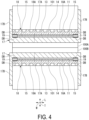
FIG. 4 is a diagram illustrating an example of heat welding of CFRTP with the heating device ofFIG. 1 . -
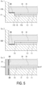
FIG. 5 is a diagram illustrating a modification example of the heating device according to the embodiment. - A
heating device 1 according to an embodiment will be described below with reference to the accompanying drawings. - As an example, the
heating device 1 is suitably used for joining two members made of carbon fiber reinforced thermoplastic plastics (hereinafter CFRTP) by welding. Theheating device 1 has a multilayer structure in which a heat generator having a sheet-like shape is sandwiched, and a portion which can be an entering path of oxygen in the multilayer structure is sealed. Theheating device 1 can reduce the oxidative consumption of aheat generator 11 by employing diffusion bonding as a preferred sealing means. - The
heating device 1 is configured by layering theheat generator 11, a pair of afirst insulator 13 and asecond insulator 14 made of electrically insulating materials respectively layered on the front and back surfaces of theheat generator 11, and a firstheat transfer body 17 and a secondheat transfer body 18 respectively layered on thefirst insulator 13 and thesecond insulator 14. - The
heat generator 11 is a sheet-like heating element that generates heat when supplied with electric power. The heat generator is made of graphite, for example, and generates heat when supplied with electric power. A graphite heater emits a large amount of infrared radiation, can generate heat in a short time of 1 second or less, and is thus suitable for heat welding of CFRTP. However, the graphite heater is merely a preferred example in the present disclosure. In addition, a carbon heater using carbon fibers as a heating element, a ceramic heater using alumina (Al2O3), silica nitride (Si3N4), or the like as a heating element, a thin metal film heater, or the like can be used in the present disclosure. - The outer shape of the
heat generator 11 is a rectangle as an example in a plan view, but may have another shape. Note that "rectangle" refers to a quadrangle having four equal corners. In addition, in order to absorb thermal expansion during heating and to increase a laying amount per unit area, it is preferable to employ a zigzag pattern. - The
first insulator 13 and thesecond insulator 14 are layered on the front and back surfaces of theheat generator 11, respectively. - The
first insulator 13 and thesecond insulator 14 are provided to electrically insulate theheat generator 11 from the firstheat transfer body 17 and the secondheat transfer body 18. The material constituting thefirst insulator 13 and thesecond insulator 14 is not limited as long as theheat generator 11 can be insulated from the firstheat transfer body 17 and the secondheat transfer body 18. However, in consideration of heat resistance, it is preferable to use mica as thefirst insulator 13 and thesecond insulator 14. - The first
heat transfer body 17 and the secondheat transfer body 18 are layered on thefirst insulator 13 and thesecond insulator 14, respectively, and constitute outer layers in theheating device 1. The firstheat transfer body 17 and the secondheat transfer body 18 transfer heat generated by theheat generator 11 supplied with electric power to outside. - The first
heat transfer body 17 is a member having a C-shaped cross-sectional shape and includes aheat transfer wall 17A having a flat shape andside walls heat transfer wall 17A in a second direction W so as to be continuous with theheat transfer wall 17A. A first surface 17A1 of theheat transfer wall 17A covers a surface of thefirst insulator 13, and a first surface 17B2 of theside wall 17B covers a side of thefirst insulator 13 and theheat generator 11. A second surface 17A2 of theheat transfer wall 17A comes into contact with and transfers heat to a CFRTP member to be fused, as theheating device 1. - The first
heat transfer body 17 is made of a material having excellent thermal conductivity and a predetermined rigidity. A heat transfer rate is exemplified as a physical property for evaluating thermal conductivity, and a material having a heat transfer rate of 10 W/m K or more at room temperature is suitably used. Young's modulus is exemplified as a physical property for evaluating a rigidity, and a material having Young's modulus of 30 GPa or more at room temperature is suitably used. Preferred specific metal materials include copper or a copper alloy, aluminum or an aluminum alloy, and a stainless steel. In addition to the metal material, highly thermal conductive fine ceramics such as aluminum nitride and silicon carbide can be used as the firstheat transfer body 17. The secondheat transfer body 18 is also made of the same type of material as the firstheat transfer body 17. However, the firstheat transfer body 17 and the secondheat transfer body 18 may be made of different materials. - The second
heat transfer body 18 is a flat member as a whole, and is disposed to face theheat transfer wall 17A of the firstheat transfer body 17 across theheat generator 11, thefirst insulator 13, and thesecond insulator 14. - In the
heating device 1, the thickness of a portion where theheat generator 11, thefirst insulator 13, thesecond insulator 14, the firstheat transfer body 17, and the secondheat transfer body 18 are layered is preferably 10 mm or less, more preferably 5 mm or less, and still more preferably 3 mm or less. - Regarding each element constituting the
heating device 1, preferably, the thickness of theheat generator 11 is 0.3 mm or less, the thicknesses of thefirst insulator 13 and thesecond insulator 14 are 0.3 mm or less, and the thicknesses of the firstheat transfer body 17 and the secondheat transfer body 18 are 1 mm or less. - The
heating device 1 is provided with acircumferential edge structure 30 for suppressing the oxidative consumption of theheat generator 11. The specific description will be given below. - The premise of this structure is that the
first insulator 13 and thesecond insulator 14 are formed to have a dimension in the second direction W larger than that of theheat generator 11 and that thefirst insulator 13 and thesecond insulator 14 protrude outward in the second direction W as compared with theheat generator 11. Athird insulator 15 is provided between thefirst insulator 13 and thesecond insulator 14 to fill a gap between thefirst insulator 13 and thesecond insulator 14. A joinedbody 19 is provided between theside wall 17B and each of thefirst insulator 13, thesecond insulator 14, and thethird insulator 15 in the second direction W. InFIG. 2 , the joinedbody 19 includes afirst surface 19A facing downward, asecond surface 19B opposing thefirst surface 19A and facing upward, athird surface 19C facing theside wall 17B side, and afourth surface 19D opposing thethird surface 19C. Theheat generator 11, thefirst insulator 13, thesecond insulator 14, thethird insulator 15, the joinedbody 19, and theside wall 17B are arranged in this order from theheat generator 11 toward a circumferential edge in the second direction W. - The joined
body 19 is a member having a cuboid shape whose dimension is larger in a first direction (L) than in the second direction W, and is made of the same material as the firstheat transfer body 17 and the secondheat transfer body 18, for example, a copper alloy. In a third direction T, the joinedbody 19 is disposed between theheat transfer wall 17A of the firstheat transfer body 17 and the secondheat transfer body 18, theheat transfer wall 17A and thefirst surface 19A are in contact with each other, and thesecond surface 19B is in contact with the secondheat transfer body 18. In the second direction W, thethird surface 19C is in contact with theside wall 17B, and thefourth surface 19D is in contact with thefirst insulator 13, thesecond insulator 14, and thethird insulator 15. - In order to reduce the oxidative consumption of the
heat generator 11, the joinedbody 19 is joined to theheat transfer wall 17A of the firstheat transfer body 17 on thefirst surface 19A, and the joinedbody 19 is joined to the secondheat transfer body 18 on thesecond surface 19B. Accordingly, an entering path through which oxygen enters theheat generator 11 is blocked. - In the present disclosure, diffusion bonding DB is employed as a preferred joining means. The diffusion bonding is a method for obtaining a metallurgically-integrated joined portion by maintaining a base material in a heated and pressurized state without being melted and causing atoms at a joining interface to diffuse through joining surfaces. In the case of the present embodiment, the joined
body 19 and theheat transfer wall 17A are metallurgically integrated, and the joinedbody 19 and the secondheat transfer body 18 are integrated, with each of thefirst surface 19A and thesecond surface 19B serving as a joining interface. Thus, it is possible to prevent oxygen from entering theheat generator 11 from these portions. The above-described joining of theheat transfer wall 17A and the secondheat transfer body 18 via the joinedbody 19 corresponds to the indirect joining in the present disclosure. Note that when a graphite heater is used as theheat generator 11, it is recommended to perform diffusion bonding in a vacuum environment in order to avoid gasification of the graphite. - In the present embodiment, any specific means may be used as long as a diffusion bonding state can be obtained by applying heat and pressure. For example, the diffusion bonding may be performed using an apparatus such as a hot press or a hot isostatic pressing (HIP). In addition, in the case of a copper alloy, it is known that a diffusion bonding state can be obtained at an interface by resistance welding accompanied by pressurization, and the diffusion bonding can also be performed by resistance welding. In the case of the example illustrated in
FIG. 2 , the resistance welding can be performed by heating while applying a load F at least between theheat transfer wall 17A and the secondheat transfer body 18. According to JIS Z 3001, the diffusion bonding is defined as "a joining method in which members are brought into close contact with each other and pressed at a temperature equal to or lower than the melting point of a base material to such an extent that plastic deformation does not occur as much as possible to realize metallic bonding between surfaces to be joined to each other." In the diffusion bonding of copper and a copper alloy, a heating temperature of about 400°C is employed. - In the present embodiment, the diffusion bonding is used for at least the following two reasons.
- The first reason is that joining target objects (the joined
body 19, theheat transfer wall 17A, and the second heat transfer body 18) are metallurgically integrated with each other, and thus entering of oxygen that causes oxidative consumption can be prevented. - The second reason is that the
first surface 19A and thesecond surface 19B, which are hidden inside by theheat transfer wall 17A and the secondheat transfer body 18, must be joined, and thus it is difficult to employ other joining methods such as welding. - Although the
circumferential edge structure 30 at both end portions in the second direction W has been described above, preferably, thecircumferential edge structure 30 is also provided at both end portions in the first direction L in plan view, as illustrated inFIG. 3 . That is, thecircumferential edge structure 30 is preferably provided across a region of a circumferential edge FR surrounding the first direction L and the second direction W. - A case in which two members made of CFRTP are joined by welding using the
heating device 1 will be described. This case is an example in which twoheating devices heat transfer bodies heat transfer body 17 and the firstheat transfer body 17. - In a space between the second
heat transfer body 18 and theside walls heat insulator 101 can be disposed without a gap. By providing theheat insulator 101, the amount of heat generated by theheat generator 11 is prevented from being discharged to the outside without being directed to the welding target objects 100A, 100B. Theheat insulator 101 also serves as a load for the welding target objects 100A, 100B. - In addition, the
heat insulator 101 is disposed so as to be in contact with the secondheat transfer body 18, thereby closing a plurality of coolinggrooves 18A formed in the secondheat transfer body 18 from the third direction T. Accordingly, thecooling grooves 18A become closed spaces except for portions in the first direction L. After heating necessary for welding the welding target objects 100A, 100B is performed, it is preferable that fused portions are immediately solidified. For this reason, after the necessary heating is performed, cooling air is continuously supplied to thecooling grooves 18A forming the closed spaces. Since the supplied air cools the welding target objects 100A, 100B via the secondheat transfer body 18, solidification of the fused portions can be facilitated. - Although an example in which two
heating devices heating device 1 may be used to fuse the welding target objects 100A, 100B. - As described above, according to the
heating device 1, since a portion which can be an entering path of oxygen to theheat generator 11 is blocked by the diffusion bonding DB, the oxidative consumption of theheat generator 11 during welding of CFRTP can be suppressed. In particular, the diffusion bonding DB metallurgically integrally bonds between the joinedbody 19 and the firstheat transfer body 17 and between the joinedbody 19 and the secondheat transfer body 18, and thus has a high degree of blocking the entering path of oxygen. - According to the
heating device 1, the diffusion bonding can be performed while applying the load F in the third direction T in which the joinedbody 19 is sandwiched between the firstheat transfer body 17 and the secondheat transfer body 18. Thus, according to theheating device 1, diffusion bonding between the joinedbody 19 and theheat transfer wall 17A and diffusion bonding between the joinedbody 19 and the secondheat transfer body 18 can be easily achieved by heating while applying the load F to the same region in the same direction. - According to the
heating device 1, since the joinedbody 19 is interposed between the firstheat transfer body 17 and the secondheat transfer body 18, plate materials having a flat and simple shape can be used as the surfaces of the firstheat transfer body 17 and the secondheat transfer body 18 facing each other including portions to be diffusion-bonded. Therefore, theheating device 1 has a low production cost. - Although an example of a preferred circumferential edge structure has been described, a circumferential edge structure described below can be employed in the present embodiment.
- The
heating device 1 performs diffusion bonding using the joinedbody 19. However, in the present disclosure, circumferential edges of the firstheat transfer body 17 and the secondheat transfer body 18 can be directly diffusion-bonded without using the joinedbody 19. This corresponds to the direct joining in the present disclosure. That is, a portion corresponding to the joinedbody 19, which is prepared as a separate body in theheating device 1, is provided at the firstheat transfer body 17 or the secondheat transfer body 18.FIG. 5 illustrates an example (Ex. 1) in which a joinedportion 17C corresponding to the joinedbody 19 is formed at the firstheat transfer body 17 and an example (Ex. 2) in which a joinedportion 18D corresponding to the joinedbody 19 is formed at the secondheat transfer body 18. The joinedportion 17C is formed so as to have a larger dimension (wall thickness) in the third direction T than other regions of theheat transfer wall 17A in the circumference of theheat transfer wall 17A and is formed along theside wall 17B. The joinedportion 18D is formed so as to have a larger dimension in the third direction T than other regions of the secondheat transfer body 18 in the circumference of the secondheat transfer body 18. When the firstheat transfer body 17 including the joinedportion 17C and the secondheat transfer body 18 including the joinedportion 18D are used, it is possible to save time and effort for preparing the joinedbody 19 in addition to the firstheat transfer body 17 and the secondheat transfer body 18. - In the example described below, the direction of the diffusion bonding is different from that in the circumferential edge structure described above. That is, although the diffusion bonding DB in the circumferential edge structure described above is provided in parallel with the first
heat transfer body 17 and the secondheat transfer body 18, the diffusion bonding DB may be provided so as to intersect, typically be orthogonal to the firstheat transfer body 17 and the secondheat transfer body 18 as in the example illustrated inFIG. 5 (Ex. 3). In this example, a portion corresponding to theside wall 17B of the firstheat transfer body 17 is prepared as a separate member from theheat transfer wall 17A. That is, aside wall 21, which is substituted for theside wall 17B, is provided on a side surface of the firstheat transfer body 17 and a side surface of the secondheat transfer body 18, and theside wall 21 and the side surface of the firstheat transfer body 17 are diffusion bonded and theside wall 21 and the side surface of the secondheat transfer body 18 are diffusion-bonded. During the diffusion bonding, a load F is applied in the direction illustrated in the drawing. - Although in the above-described embodiment, the diffusion bonding is exemplified as a preferred joining method, the present disclosure can employ other joining methods exemplified below.
- (1) Material joining
- (a) Arc welding, gas welding, resistance welding, and laser welding
- (b) Brazing and soldering
- (c) Friction stir welding (FSW)
- (2) Chemical joining
Adhesion (using heat-resistant inorganic adhesive) - (3) Mechanical joining
- (a) Fastening
- (b) Shrink fitting and freeze fitting
- In addition, other elements can be added to the configuration described in the above-described embodiment. For example, another layer such as a highly thermal conductive sheet may be interposed between the second
heat transfer body 18 and thesecond insulator 14 in order to suppress in-plane temperature unevenness of theheat generator 11. - The present disclosure can be apprehended as follows.
- A heating device (1) including:
- a heat generator (11) configured to generate heat when supplied with electric power;
- a first insulator (13) and a second insulator (14) respectively layered on a front surface and a back surface of the heat generator (11) and each covering the heat generator (11);
- a first heat transfer body (17) layered on the first insulator (13) and covering the first insulator (13) and a second heat transfer body (18) layered on the second insulator (14) and covering the second insulator (14); and
- a circumferential edge structure (30) configured to seal circumferential edges (FR) of the first insulator (13) and the second insulator (14), wherein
- in the circumferential edge structure (30), the circumferential edges are sealed by direct or indirect joining of the first heat transfer body (17) and the second heat transfer body (18).
- In
Supplementary Note 1, preferably, circumferential edges of the first heat transfer body (17) and the second heat transfer body (18) protrude to an outer side from the circumferential edges of the first insulator (13) and the second insulator (14), the circumferential edge structure (30) includes a joined body (19) disposed on the outer side from the first insulator (13) and the second insulator (14) and fitted to the first heat transfer body (17) and the second heat transfer body (18), the first heat transfer body (17) is diffusion-bonded to the joined body (19), and the second heat transfer body (18) is diffusion-bonded to the joined body (19). - In
Supplementary Note - In any one of
Supplementary Notes 1 to 3, preferably, the first heat transfer body (17) includes a heat transfer wall (17A) having a rectangular shape in plan view having a first direction (L) and a second direction (W) orthogonal to the first direction (L) and includes a pair of side walls (17B, 17B) rising from both sides of the heat transfer wall (17A) in the second direction (W), and the heat transfer wall (17A) and the pair of side walls (17B, 17B) are integrally formed. - In any one of
Supplementary Notes 1 to 4, preferably, the second heat transfer body (18) has a rectangular shape in plan view having a first direction (L) and a second direction (W) orthogonal to the first direction (L) and includes a first surface (18B) in contact with the second insulator (14) and a second surface (18C) on a back side of the first surface (18B), and a plurality of cooling grooves (18A) for flowing a cooling medium is formed in the second surface (18C) along the first direction (L). - In any one of
Supplementary Notes 1 to 5, preferably, the heat generator (11) is made of a sheet-like heater made of graphite, and the first heat transfer body (17) and the second heat transfer body (18) are made of a copper alloy. - Besides the above-described embodiment, configurations described in the above-described embodiment can be selected or omitted as desired or can be changed to other configurations as necessary.
-
- 1 Heating device
- 11 Heat generator
- 13 First insulator
- 14 Second insulator
- 15 Third insulator
- 17 First heat transfer body
- 17A Heat transfer wall
- 17A1 First surface
- 17A2 Second surface
- 17B Side wall
- 17C Joined portion
- 18 Second heat transfer body
- 18A Cooling groove
- 18B First surface
- 18C Second surface
- 18D Joined portion
- 19 Joined body
- 19A First surface
- 19B Second surface
- 19C Third surface
- 19D Fourth surface
- 21 Side wall
- 30 Circumferential edge structure
- 100A, 100B Welding target object
- 101 Heat insulator
- DB Diffusion bonding
- F Load
- L First direction
- W Second direction
- T Third direction
Claims (6)
- A heating device, comprising:a heat generator configured to generate heat when supplied with electric power;a first insulator and a second insulator respectively layered on a front surface and a back surface of the heat generator and each covering the heat generator;a first heat transfer body layered on the first insulator and covering the first insulator and a second heat transfer body layered on the second insulator and covering the second insulator; anda circumferential edge structure configured to seal circumferential edges of the first insulator and the second insulator, whereinin the circumferential edge structure, the circumferential edges are sealed by direct or indirect joining of the first heat transfer body and the second heat transfer body.
- The heating device according to claim 1, whereincircumferential edges of the first heat transfer body and the second heat transfer body protrude to an outer side from the circumferential edges of the first insulator and the second insulator,the circumferential edge structure includes a joined body disposed on the outer side from the first insulator and the second insulator and fitted to the first heat transfer body and the second heat transfer body,the first heat transfer body is diffusion-bonded to the joined body, and the second heat transfer body diffusion-bonded to the joined body.
- The heating device according to claim 2, whereinthe first heat transfer body and the second heat transfer body have a rectangular shape in plan view having a first direction and a second direction orthogonal to the first direction, andthe circumferential edge structure is provided across the circumferential edges of the first heat transfer body and the second heat transfer body.
- The heating device according to claim 1, whereinthe first heat transfer body includes a heat transfer wall having a rectangular shape in plan view having a first direction and a second direction orthogonal to the first direction and a pair of side walls rising from both sides of the heat transfer wall in the second direction, andthe heat transfer wall and the pair of side walls are integrally formed.
- The heating device according to claim 1, whereinthe second heat transfer body has a rectangular shape in plan view having a first direction and a second direction orthogonal to the first direction and includes a first surface in contact with the second insulator and a second surface on a back side of the first surface, anda plurality of cooling grooves for flowing a cooling medium is formed in the second surface along the first direction.
- The heating device according to any one of claims 1 to 5, whereinthe heat generator is made of a sheet-like heater made of graphite, andthe first heat transfer body and the second heat transfer body are made of copper or a copper alloy.
Applications Claiming Priority (1)
| Application Number | Priority Date | Filing Date | Title |
|---|---|---|---|
| JP2023147379A JP2025040523A (en) | 2023-09-12 | 2023-09-12 | Heating Device |
Publications (1)
| Publication Number | Publication Date |
|---|---|
| EP4523892A1 true EP4523892A1 (en) | 2025-03-19 |
Family
ID=92424214
Family Applications (1)
| Application Number | Title | Priority Date | Filing Date |
|---|---|---|---|
| EP24194513.8A Pending EP4523892A1 (en) | 2023-09-12 | 2024-08-14 | Heating device |
Country Status (3)
| Country | Link |
|---|---|
| US (1) | US20250089131A1 (en) |
| EP (1) | EP4523892A1 (en) |
| JP (1) | JP2025040523A (en) |
Citations (2)
| Publication number | Priority date | Publication date | Assignee | Title |
|---|---|---|---|---|
| WO2015098133A1 (en) * | 2013-12-26 | 2015-07-02 | 日産自動車株式会社 | Heat sealer |
| JP7275246B1 (en) | 2021-12-28 | 2023-05-17 | 三菱重工業株式会社 | Fusion device and fusion method |
Family Cites Families (3)
| Publication number | Priority date | Publication date | Assignee | Title |
|---|---|---|---|---|
| JP2008047500A (en) * | 2006-08-21 | 2008-02-28 | Nhk Spring Co Ltd | Heater unit and manufacturing method thereof |
| GB2493001B (en) * | 2011-07-21 | 2016-05-11 | Laminaheat Holding Ltd | Laminate items |
| US11818813B2 (en) * | 2018-09-28 | 2023-11-14 | Kyocera Corporation | Wafer-use member, wafer-use system, and method for manufacturing wafer-use member |
-
2023
- 2023-09-12 JP JP2023147379A patent/JP2025040523A/en active Pending
-
2024
- 2024-08-05 US US18/793,944 patent/US20250089131A1/en active Pending
- 2024-08-14 EP EP24194513.8A patent/EP4523892A1/en active Pending
Patent Citations (2)
| Publication number | Priority date | Publication date | Assignee | Title |
|---|---|---|---|---|
| WO2015098133A1 (en) * | 2013-12-26 | 2015-07-02 | 日産自動車株式会社 | Heat sealer |
| JP7275246B1 (en) | 2021-12-28 | 2023-05-17 | 三菱重工業株式会社 | Fusion device and fusion method |
Also Published As
| Publication number | Publication date |
|---|---|
| JP2025040523A (en) | 2025-03-25 |
| US20250089131A1 (en) | 2025-03-13 |
Similar Documents
| Publication | Publication Date | Title |
|---|---|---|
| JP7757480B2 (en) | heat sink | |
| JP4829552B2 (en) | Thermoelectric conversion module | |
| US20110265838A1 (en) | Packaged thermoelectric conversion module | |
| JP5642419B2 (en) | Thermoelectric conversion module with airtight case | |
| JP2636119B2 (en) | Thermoelectric element sheet and manufacturing method thereof | |
| JP5858594B2 (en) | Thermal management device and method of manufacturing thermal management device | |
| JP4121679B2 (en) | Temperature controller and manufacturing method thereof | |
| JP5954008B2 (en) | Heat spreader | |
| US20180261751A1 (en) | Method for producing a thermoelectric module | |
| JPH09276076A (en) | Temperature control device | |
| US20180204993A1 (en) | Heat-conductive and electrically insulating connection for a thermoelectric module | |
| CN116888810A (en) | Cooling structure between battery cells, battery modules and battery packs | |
| JP2023149660A (en) | Wafer mounting table | |
| JP4775932B2 (en) | Cushion for heat transfer and thermoelectric conversion module having the same | |
| US20250089131A1 (en) | Heating device | |
| CN108860814B (en) | Sealing means | |
| JP6428749B2 (en) | Thermoelectric generator | |
| Kambe et al. | Encapsulated thermoelectric modules and compliant pads for advanced thermoelectric systems | |
| JP5869399B2 (en) | Channel member, heat exchanger using the same, and semiconductor device | |
| JP7275246B1 (en) | Fusion device and fusion method | |
| KR101887151B1 (en) | Diffusion bonding apparatus | |
| JP2017063091A (en) | Thermoelectric conversion system | |
| JP6424883B2 (en) | Thermoelectric generator | |
| JP3175039B2 (en) | Thermoelectric conversion module, laminated thermoelectric conversion device, thermoelectric power generation subunit, and power generation system | |
| JP3958120B2 (en) | High thermal conductive composite material and honeycomb sandwich panel using this as a skin material |
Legal Events
| Date | Code | Title | Description |
|---|---|---|---|
| PUAI | Public reference made under article 153(3) epc to a published international application that has entered the european phase |
Free format text: ORIGINAL CODE: 0009012 |
|
| STAA | Information on the status of an ep patent application or granted ep patent |
Free format text: STATUS: REQUEST FOR EXAMINATION WAS MADE |
|
| 17P | Request for examination filed |
Effective date: 20240814 |
|
| AK | Designated contracting states |
Kind code of ref document: A1 Designated state(s): AL AT BE BG CH CY CZ DE DK EE ES FI FR GB GR HR HU IE IS IT LI LT LU LV MC ME MK MT NL NO PL PT RO RS SE SI SK SM TR |