EP4523826A1 - Funkenerosionsmaschine - Google Patents
Funkenerosionsmaschine Download PDFInfo
- Publication number
- EP4523826A1 EP4523826A1 EP22947995.1A EP22947995A EP4523826A1 EP 4523826 A1 EP4523826 A1 EP 4523826A1 EP 22947995 A EP22947995 A EP 22947995A EP 4523826 A1 EP4523826 A1 EP 4523826A1
- Authority
- EP
- European Patent Office
- Prior art keywords
- clean water
- conduit
- electrical discharge
- discharge machine
- wastewater
- Prior art date
- Legal status (The legal status is an assumption and is not a legal conclusion. Google has not performed a legal analysis and makes no representation as to the accuracy of the status listed.)
- Pending
Links
Images


Classifications
-
- B—PERFORMING OPERATIONS; TRANSPORTING
- B23—MACHINE TOOLS; METAL-WORKING NOT OTHERWISE PROVIDED FOR
- B23H—WORKING OF METAL BY THE ACTION OF A HIGH CONCENTRATION OF ELECTRIC CURRENT ON A WORKPIECE USING AN ELECTRODE WHICH TAKES THE PLACE OF A TOOL; SUCH WORKING COMBINED WITH OTHER FORMS OF WORKING OF METAL
- B23H1/00—Electrical discharge machining, i.e. removing metal with a series of rapidly recurring electrical discharges between an electrode and a workpiece in the presence of a fluid dielectric
- B23H1/10—Supply or regeneration of working media
Definitions
- JP 2013-132735 A discloses maintaining the resistivity of a dielectric working fluid at a value higher than a predetermined value by using an ion exchange resin to reduce the ion concentration in the dielectric working fluid.
- the present invention has the object of solving the aforementioned problem.
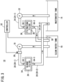
- the electrical discharge machine 10 includes a wastewater tank 14, a clean water tank 16, a first pump 18, a first conduit 20, a second pump 22, a second conduit 24, a sludge filter 26, an on-off valve 28, a resistivity meter 30, and a controller 32.
- the wastewater tank 14 is a tank for storing wastewater.
- the wastewater is a dielectric working fluid containing machining chips generated by machining of the workpiece.
- the clean water tank 16 is a tank for storing clean water.
- the clean water is a dielectric working fluid obtained by removing machining chips from the wastewater.
- the machining chips contain at least one of iron, aluminum, copper, zinc, tungsten carbide, tungsten, molybdenum, carbon, titanium, silicon, manganese, chromium, phosphorus, sulfur, and nickel.
- the filter container 34 includes a first fluid inlet 34-1, a second fluid inlet 34-2 and a fluid outlet 34-3.
- the first fluid inlet 34-1, the second fluid inlet 34-2, and the fluid outlet 34-3 communicate with a filter accommodation space inside the filter container 34.
- the filter accommodation space is a space in which the sludge filter 26 is accommodated.
- the first fluid inlet 34-1 and the second fluid inlet 34-2 are arranged, for example, in the upper wall of the filter container 34.
- the first fluid inlet 34-1 and the second fluid inlet 34-2 may be arranged in the side wall of the filter container 34.
- the fluid outlet 34-3 is arranged, for example, in the lower wall of the filter container 34.
- the fluid outlet 34-3 may be arranged in the side wall of the filter container 34.
- the first fluid inlet 34-1 is connected to an end portion (a downstream end portion) of the first conduit 20.
- the second fluid inlet 34-2 is connected to an end portion (a downstream end portion) of the upstream portion 24-1 of the second conduit 24.
- the fluid outlet 34-3 is connected to an end portion (an upstream end portion) of the downstream portion 24-2 of the second conduit 24.
- the downstream portion 24-2 of the second conduit 24 may be removed.
- the sludge filter 26 makes the resistivity of the clean water larger than the resistivity of clean water stored in the clean water tank 16. In this case, the sludge filter 26 increases the resistivity of the clean water by causing the clean water to pass through the pores in which the machining chips are trapped.
- the clean water stored in the clean water tank 16 can be caused to pass through the pores of the sludge filter 26 to improve the resistivity of the clean water.
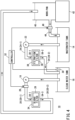
- FIG. 3 is a schematic view showing a configuration of the electrical discharge machine 10 according to a second modification.
- the same components as those described in the embodiment and the first modification are denoted by the same reference numerals. It should be noted that, in the present modification, descriptions that are duplicative of those given in the embodiment will be omitted.
- the first conduit 20 is different from that of the first modification.
- the first conduit 20 is formed so that the clean water flows to the clean water tank 16 through the sludge filter 26.
- the first conduit 20 is formed so that the clean water flows to the wastewater tank 14 through the sludge filter 26.
- the downstream portion 20-2 of the first conduit 20 guides the clean water flowing out from the sludge filter 26 to the wastewater tank 14.
- a work-pan 40 is newly provided.
- the work-pan 40 is a tank that stores a dielectric working fluid for immersing a workpiece.
- the work-pan 40 is installed on the upper surface of an installation base 42.
- the first conduit 20 is formed so that the clean water flows to the work-pan 40 through the sludge filter 26.
- the downstream portion 20-2 of the first conduit 20 guides the clean water flowing out from the sludge filter 26 to the work-pan 40.
- the resistivity of the clean water can be improved as in the first modification.
- the controller 32 opens the on-off valve 46 at a predetermined timing such as when the machining of the workpiece is finished, and discharges the dielectric working fluid stored in the work-pan 40 to the wastewater tank 14.
- the controller 32 may open the on-off valve 28 and drive the first pump 18 to supply, to the work-pan 40, the clean water in an amount corresponding to the amount of the dielectric working fluid discharged to the wastewater tank 14. This can suppress a significant increase in the ion concentration of the dielectric working fluid stored in the work-pan 40, and as a result, can suppress a decrease in the machine accuracy.
- the resistivity meter 30 may be replaced by a conductivity meter.
- the conductivity meter measures the conductivity of the clean water stored in the clean water tank 16 and outputs a signal indicating the conductivity to the controller 32.
- the controller 32 compares the conductivity measured by the conductivity meter with a predetermined threshold. Further, in the present modification, in a case where the conductivity is equal to or higher than the predetermined threshold, the controller 32 drives the first pump 18 and opens the on-off valve 28.
- the present modification is not limited to being applied to the embodiment, and can be applied to any of the first to third modifications.
- the controller 32 may control an inverter that drives the first pump 18 to adjust the flow rate of the clean water in the first conduit 20.
- the on-off valve 28 may be removed.
- the controller 32 may adjust the flow rate of the clean water in the first conduit 20 by controlling the opening degree of the on-off valve 28.
- the present modification is not limited to being applied to the embodiment, and can be applied to any of the first to third modifications.
- the sludge filter 26 may be provided in the clean water tank 16.
- the present modification is not limited to being applied to the embodiment, and can be applied to any of the first to third modifications.
Landscapes
- Engineering & Computer Science (AREA)
- Mechanical Engineering (AREA)
- Electrical Discharge Machining, Electrochemical Machining, And Combined Machining (AREA)
Applications Claiming Priority (1)
| Application Number | Priority Date | Filing Date | Title |
|---|---|---|---|
| PCT/JP2022/025144 WO2023248434A1 (ja) | 2022-06-23 | 2022-06-23 | 放電加工機 |
Publications (1)
| Publication Number | Publication Date |
|---|---|
| EP4523826A1 true EP4523826A1 (de) | 2025-03-19 |
Family
ID=89379300
Family Applications (1)
| Application Number | Title | Priority Date | Filing Date |
|---|---|---|---|
| EP22947995.1A Pending EP4523826A1 (de) | 2022-06-23 | 2022-06-23 | Funkenerosionsmaschine |
Country Status (5)
| Country | Link |
|---|---|
| EP (1) | EP4523826A1 (de) |
| JP (1) | JPWO2023248434A1 (de) |
| CN (1) | CN119365286A (de) |
| TW (1) | TW202400333A (de) |
| WO (1) | WO2023248434A1 (de) |
Family Cites Families (5)
| Publication number | Priority date | Publication date | Assignee | Title |
|---|---|---|---|---|
| JPH03221322A (ja) * | 1988-10-11 | 1991-09-30 | Taiyo Kogyo Kk | 放電加工方法及びその装置 |
| US5434381A (en) * | 1993-09-13 | 1995-07-18 | T-Star Industrial Electronics, Inc. | Apparatus for filtering machining liquid of an electrical discharge machine |
| JP2013132735A (ja) | 2011-12-27 | 2013-07-08 | Fanuc Ltd | 不活性ガスを加工液に溶解させるワイヤ放電加工機及びワイヤ放電加工方法 |
| JP2016055372A (ja) * | 2014-09-08 | 2016-04-21 | ファナック株式会社 | イオン交換装置の寿命判定機能を備えた放電加工機 |
| JP2017042899A (ja) * | 2015-08-29 | 2017-03-02 | 株式会社橋本テクニカル工業 | 放電加工液処理装置、放電加工製品の製造方法及び放電加工装置 |
-
2022
- 2022-06-23 EP EP22947995.1A patent/EP4523826A1/de active Pending
- 2022-06-23 JP JP2024528215A patent/JPWO2023248434A1/ja active Pending
- 2022-06-23 CN CN202280097012.3A patent/CN119365286A/zh active Pending
- 2022-06-23 WO PCT/JP2022/025144 patent/WO2023248434A1/ja not_active Ceased
-
2023
- 2023-06-20 TW TW112123026A patent/TW202400333A/zh unknown
Also Published As
| Publication number | Publication date |
|---|---|
| WO2023248434A1 (ja) | 2023-12-28 |
| JPWO2023248434A1 (de) | 2023-12-28 |
| CN119365286A (zh) | 2025-01-24 |
| TW202400333A (zh) | 2024-01-01 |
Similar Documents
| Publication | Publication Date | Title |
|---|---|---|
| EP4523826A1 (de) | Funkenerosionsmaschine | |
| CN104972187A (zh) | 线放电加工机 | |
| CN211414557U (zh) | 加工中心用水箱 | |
| JP5727562B2 (ja) | 放電加工機の濾過フィルタ | |
| JP7438039B2 (ja) | 切削液タンク | |
| TWI884317B (zh) | 壽命預測裝置及工具機 | |
| CN102655973B (zh) | 防蚀装置、防蚀方法以及线电极放电加工装置 | |
| CN116000395A (zh) | 用于电火花线切割机的水循环系统及控制方式 | |
| CN211170910U (zh) | 硅钢酸洗废酸排放管路清洗装置 | |
| EP4559608A1 (de) | Elektroerosionsbearbeitungsvorrichtung | |
| EP4631659A1 (de) | Vorrichtung zur aufbereitung von bearbeitungswasser | |
| EP4717389A1 (de) | Flüssigkeitsfiltriervorrichtung und verarbeitungssystem | |
| JP5796504B2 (ja) | スラリー供給装置の制御方法 | |
| JP7711156B2 (ja) | クーラントタンク、及び、工作機械 | |
| KR102732927B1 (ko) | 유수분리장치 | |
| WO2024262006A1 (ja) | 放電加工機 | |
| WO2023248435A1 (ja) | 調整装置、調整方法および製造方法 | |
| WO2024247147A1 (ja) | 液体濾過装置の制御装置及び加工システム | |
| CN120479065A (zh) | 一种废切削液的过滤装置及过滤方法 | |
| CN121100038A (zh) | 控制装置、放电加工机及控制方法 | |
| JP2007002682A (ja) | 内燃機関の油圧装置 | |
| GB1592720A (en) | Electrolytic methodfor breaking an oil-inwater emulsion | |
| JP6466045B1 (ja) | 電気分解装置及び放電加工装置 | |
| KR100693029B1 (ko) | 유화유 폐수의 유수분리장치 및 방법 | |
| CN114082237A (zh) | 一种双氧水聚结分离除碳设备 |
Legal Events
| Date | Code | Title | Description |
|---|---|---|---|
| STAA | Information on the status of an ep patent application or granted ep patent |
Free format text: STATUS: THE INTERNATIONAL PUBLICATION HAS BEEN MADE |
|
| PUAI | Public reference made under article 153(3) epc to a published international application that has entered the european phase |
Free format text: ORIGINAL CODE: 0009012 |
|
| STAA | Information on the status of an ep patent application or granted ep patent |
Free format text: STATUS: REQUEST FOR EXAMINATION WAS MADE |
|
| 17P | Request for examination filed |
Effective date: 20241211 |
|
| AK | Designated contracting states |
Kind code of ref document: A1 Designated state(s): AL AT BE BG CH CY CZ DE DK EE ES FI FR GB GR HR HU IE IS IT LI LT LU LV MC MK MT NL NO PL PT RO RS SE SI SK SM TR |
|
| DAV | Request for validation of the european patent (deleted) | ||
| DAX | Request for extension of the european patent (deleted) |