EP4523826A1 - Electrical discharge machine - Google Patents
Electrical discharge machine Download PDFInfo
- Publication number
- EP4523826A1 EP4523826A1 EP22947995.1A EP22947995A EP4523826A1 EP 4523826 A1 EP4523826 A1 EP 4523826A1 EP 22947995 A EP22947995 A EP 22947995A EP 4523826 A1 EP4523826 A1 EP 4523826A1
- Authority
- EP
- European Patent Office
- Prior art keywords
- clean water
- conduit
- electrical discharge
- discharge machine
- wastewater
- Prior art date
- Legal status (The legal status is an assumption and is not a legal conclusion. Google has not performed a legal analysis and makes no representation as to the accuracy of the status listed.)
- Pending
Links
Images


Classifications
-
- B—PERFORMING OPERATIONS; TRANSPORTING
- B23—MACHINE TOOLS; METAL-WORKING NOT OTHERWISE PROVIDED FOR
- B23H—WORKING OF METAL BY THE ACTION OF A HIGH CONCENTRATION OF ELECTRIC CURRENT ON A WORKPIECE USING AN ELECTRODE WHICH TAKES THE PLACE OF A TOOL; SUCH WORKING COMBINED WITH OTHER FORMS OF WORKING OF METAL
- B23H1/00—Electrical discharge machining, i.e. removing metal with a series of rapidly recurring electrical discharges between an electrode and a workpiece in the presence of a fluid dielectric
- B23H1/10—Supply or regeneration of working media
Definitions
- JP 2013-132735 A discloses maintaining the resistivity of a dielectric working fluid at a value higher than a predetermined value by using an ion exchange resin to reduce the ion concentration in the dielectric working fluid.
- the present invention has the object of solving the aforementioned problem.
- the electrical discharge machine 10 includes a wastewater tank 14, a clean water tank 16, a first pump 18, a first conduit 20, a second pump 22, a second conduit 24, a sludge filter 26, an on-off valve 28, a resistivity meter 30, and a controller 32.
- the wastewater tank 14 is a tank for storing wastewater.
- the wastewater is a dielectric working fluid containing machining chips generated by machining of the workpiece.
- the clean water tank 16 is a tank for storing clean water.
- the clean water is a dielectric working fluid obtained by removing machining chips from the wastewater.
- the machining chips contain at least one of iron, aluminum, copper, zinc, tungsten carbide, tungsten, molybdenum, carbon, titanium, silicon, manganese, chromium, phosphorus, sulfur, and nickel.
- the filter container 34 includes a first fluid inlet 34-1, a second fluid inlet 34-2 and a fluid outlet 34-3.
- the first fluid inlet 34-1, the second fluid inlet 34-2, and the fluid outlet 34-3 communicate with a filter accommodation space inside the filter container 34.
- the filter accommodation space is a space in which the sludge filter 26 is accommodated.
- the first fluid inlet 34-1 and the second fluid inlet 34-2 are arranged, for example, in the upper wall of the filter container 34.
- the first fluid inlet 34-1 and the second fluid inlet 34-2 may be arranged in the side wall of the filter container 34.
- the fluid outlet 34-3 is arranged, for example, in the lower wall of the filter container 34.
- the fluid outlet 34-3 may be arranged in the side wall of the filter container 34.
- the first fluid inlet 34-1 is connected to an end portion (a downstream end portion) of the first conduit 20.
- the second fluid inlet 34-2 is connected to an end portion (a downstream end portion) of the upstream portion 24-1 of the second conduit 24.
- the fluid outlet 34-3 is connected to an end portion (an upstream end portion) of the downstream portion 24-2 of the second conduit 24.
- the downstream portion 24-2 of the second conduit 24 may be removed.
- the sludge filter 26 makes the resistivity of the clean water larger than the resistivity of clean water stored in the clean water tank 16. In this case, the sludge filter 26 increases the resistivity of the clean water by causing the clean water to pass through the pores in which the machining chips are trapped.
- the clean water stored in the clean water tank 16 can be caused to pass through the pores of the sludge filter 26 to improve the resistivity of the clean water.
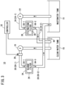
- FIG. 3 is a schematic view showing a configuration of the electrical discharge machine 10 according to a second modification.
- the same components as those described in the embodiment and the first modification are denoted by the same reference numerals. It should be noted that, in the present modification, descriptions that are duplicative of those given in the embodiment will be omitted.
- the first conduit 20 is different from that of the first modification.
- the first conduit 20 is formed so that the clean water flows to the clean water tank 16 through the sludge filter 26.
- the first conduit 20 is formed so that the clean water flows to the wastewater tank 14 through the sludge filter 26.
- the downstream portion 20-2 of the first conduit 20 guides the clean water flowing out from the sludge filter 26 to the wastewater tank 14.
- a work-pan 40 is newly provided.
- the work-pan 40 is a tank that stores a dielectric working fluid for immersing a workpiece.
- the work-pan 40 is installed on the upper surface of an installation base 42.
- the first conduit 20 is formed so that the clean water flows to the work-pan 40 through the sludge filter 26.
- the downstream portion 20-2 of the first conduit 20 guides the clean water flowing out from the sludge filter 26 to the work-pan 40.
- the resistivity of the clean water can be improved as in the first modification.
- the controller 32 opens the on-off valve 46 at a predetermined timing such as when the machining of the workpiece is finished, and discharges the dielectric working fluid stored in the work-pan 40 to the wastewater tank 14.
- the controller 32 may open the on-off valve 28 and drive the first pump 18 to supply, to the work-pan 40, the clean water in an amount corresponding to the amount of the dielectric working fluid discharged to the wastewater tank 14. This can suppress a significant increase in the ion concentration of the dielectric working fluid stored in the work-pan 40, and as a result, can suppress a decrease in the machine accuracy.
- the resistivity meter 30 may be replaced by a conductivity meter.
- the conductivity meter measures the conductivity of the clean water stored in the clean water tank 16 and outputs a signal indicating the conductivity to the controller 32.
- the controller 32 compares the conductivity measured by the conductivity meter with a predetermined threshold. Further, in the present modification, in a case where the conductivity is equal to or higher than the predetermined threshold, the controller 32 drives the first pump 18 and opens the on-off valve 28.
- the present modification is not limited to being applied to the embodiment, and can be applied to any of the first to third modifications.
- the controller 32 may control an inverter that drives the first pump 18 to adjust the flow rate of the clean water in the first conduit 20.
- the on-off valve 28 may be removed.
- the controller 32 may adjust the flow rate of the clean water in the first conduit 20 by controlling the opening degree of the on-off valve 28.
- the present modification is not limited to being applied to the embodiment, and can be applied to any of the first to third modifications.
- the sludge filter 26 may be provided in the clean water tank 16.
- the present modification is not limited to being applied to the embodiment, and can be applied to any of the first to third modifications.
Landscapes
- Engineering & Computer Science (AREA)
- Mechanical Engineering (AREA)
- Electrical Discharge Machining, Electrochemical Machining, And Combined Machining (AREA)
Abstract
Description
- The present invention relates to an electrical discharge machine.
- The electrical discharge machine machines a workpiece disposed in a dielectric working fluid by electrical discharge. By this machining, the metal of the workpiece or the like is formed as ions in the dielectric working fluid. In general, an ion exchange resin is used to reduce the metal ion concentration in the dielectric working fluid.
-
JP 2013-132735 A - However, the ion exchange resin has a life, and the ion exchange resin needs to be replaced after about 300 hours. If the ion exchange resin is not replaced, the machine accuracy becomes unstable, and therefore, the running cost for maintaining the machine accuracy tends to increase. Therefore, efficiently improving the resistivity of the dielectric working fluid has been a problem.
- The present invention has the object of solving the aforementioned problem.
- According to an aspect of the present invention, there is provided an electrical discharge machine for machining a workpiece disposed in a dielectric working fluid by electrical discharge, the electrical discharge machine comprising: a wastewater tank configured to store wastewater which is the dielectric working fluid containing machining chips generated by machining of the workpiece; a clean water tank configured to store clean water which is the dielectric working fluid obtained by removing the machining chips from the wastewater; a first conduit configured to guide the clean water pumped up from the clean water tank; and a sludge filter which is a porous body including pores through which the clean water supplied from the first conduit passes, the machining chips being trapped in the pores.
- According to the above aspect, the clean water from which the machining chips have been removed is intentionally caused to pass through the pores in which the machining chips have been trapped, whereby the resistivity of the clean water can be increased. Therefore, the resistivity of the clean water can be improved without using a generally used ion exchange resin. As a result, the resistivity of the dielectric working fluid can be efficiently improved.
- The reciprocal of the resistivity [Ωm] is the conductivity [S/m], and there is a correlation between the resistivity [Ωm] and the conductivity [S/m]. Therefore, the resistivity [Ωm] can be replaced with the conductivity [S/m]. When the resistivity [Ωm] is replaced with the conductivity [S/m], the magnitude relationship of the values is reversed. For example, "increasing the resistivity [Ωm]" is synonymous with "decreasing the conductivity [S/m]".
-
- [
FIG. 1] FIG. 1 is a schematic view showing a configuration of an electrical discharge machine according to an embodiment; - [
FIG. 2] FIG. 2 is a schematic view showing a configuration of the electrical discharge machine according to a first modification; - [
FIG. 3] FIG. 3 is a schematic view showing a configuration of the electrical discharge machine according to a second modification; and - [
FIG. 4] FIG. 4 is a schematic view showing a configuration of the electrical discharge machine according to a third modification. -
FIG. 1 is a schematic view showing a configuration of anelectrical discharge machine 10 according to an embodiment. Theelectrical discharge machine 10 machines a workpiece disposed in a dielectric working fluid by electrical discharge. Theelectrical discharge machine 10 may be a wire electrical discharge machine or a die-sinking electrical discharge machine. The wire electrical discharge machine generates electrical discharge at a machining gap formed between a wire electrode and a workpiece. The die-sinking electrical discharge machine generates an electrical discharge at a machining gap formed between a die-sinking electrode and a workpiece. - The dielectric working fluid is a liquid used for machining the workpiece. The dielectric working fluid may be water. The workpiece is a metal such as an iron-based material or a tungsten carbide material, an aluminum-based material, a copper alloy-based material, a nickel-based material, or a titanium-based material. The electrode (the wire electrode or the die-sinking electrode) of the
electrical discharge machine 10 is a metal such as a tungsten-based metal, a copper alloy-based metal, a brass-based metal, a titanium-based metal, a zinc-coated brass-based metal, or an iron-based metal, a molybdenum-based metal, or a carbon-based metal used as a core material of a brass-based metal. It should be noted that a case where the carbon-based metal is used is limited to a case where theelectrical discharge machine 10 is a die-sinking electrical discharge machine. - The
electrical discharge machine 10 includes awastewater tank 14, aclean water tank 16, afirst pump 18, afirst conduit 20, asecond pump 22, asecond conduit 24, asludge filter 26, an on-offvalve 28, aresistivity meter 30, and acontroller 32. - The
wastewater tank 14 is a tank for storing wastewater. The wastewater is a dielectric working fluid containing machining chips generated by machining of the workpiece. Theclean water tank 16 is a tank for storing clean water. The clean water is a dielectric working fluid obtained by removing machining chips from the wastewater. The machining chips contain at least one of iron, aluminum, copper, zinc, tungsten carbide, tungsten, molybdenum, carbon, titanium, silicon, manganese, chromium, phosphorus, sulfur, and nickel. - The
first pump 18 pumps up clean water from theclean water tank 16 and applies a flow force to the clean water. Thefirst pump 18 is provided in thefirst conduit 20. Thefirst conduit 20 guides the clean water pumped up from theclean water tank 16. In the present embodiment, thefirst conduit 20 guides the clean water to thesludge filter 26. - The
second pump 22 pumps up the wastewater from thewastewater tank 14 and applies a flow force to the wastewater. Thesecond pump 22 is provided in thesecond conduit 24. In the present embodiment, thesecond pump 22 is provided in thesecond conduit 24 between thewastewater tank 14 and thesludge filter 26. Thesecond conduit 24 guides the dielectric working fluid from thewastewater tank 14 to theclean water tank 16. Thesecond conduit 24 includes an upstream portion 24-1 and a downstream portion 24-2. The upstream portion 24-1 guides the wastewater pumped up from thewastewater tank 14 to thesludge filter 26. The downstream portion 24-2 guides the clean water flowing out from thesludge filter 26 to theclean water tank 16. - The
sludge filter 26 is a porous body including pores. Machining chips generated by machining of the workpiece are trapped in the pores. Thesludge filter 26 may be a porous body that has been used in the past to remove machining chips. Examples of the porous body include filter paper and filter cloth. Thesludge filter 26 is accommodated in afilter container 34. Thesludge filter 26 accommodated in thefilter container 34 may be joined to thefilter container 34. - The
filter container 34 includes a first fluid inlet 34-1, a second fluid inlet 34-2 and a fluid outlet 34-3. The first fluid inlet 34-1, the second fluid inlet 34-2, and the fluid outlet 34-3 communicate with a filter accommodation space inside thefilter container 34. The filter accommodation space is a space in which thesludge filter 26 is accommodated. - The first fluid inlet 34-1 and the second fluid inlet 34-2 are arranged, for example, in the upper wall of the
filter container 34. The first fluid inlet 34-1 and the second fluid inlet 34-2 may be arranged in the side wall of thefilter container 34. The fluid outlet 34-3 is arranged, for example, in the lower wall of thefilter container 34. The fluid outlet 34-3 may be arranged in the side wall of thefilter container 34. The first fluid inlet 34-1 is connected to an end portion (a downstream end portion) of thefirst conduit 20. The second fluid inlet 34-2 is connected to an end portion (a downstream end portion) of the upstream portion 24-1 of thesecond conduit 24. The fluid outlet 34-3 is connected to an end portion (an upstream end portion) of the downstream portion 24-2 of thesecond conduit 24. In a case where the dielectric working fluid is allowed to flow from the fluid outlet 34-3 to theclean water tank 16 by free fall, the downstream portion 24-2 of thesecond conduit 24 may be removed. - Either wastewater or clean water is selectively supplied to the
sludge filter 26. The wastewater is supplied from thewastewater tank 14 through thesecond conduit 24 and the second fluid inlet 34-2 in this order. The clean water is supplied from theclean water tank 16 through thefirst conduit 20 and the first fluid inlet 34-1 in this order. - In a case where the wastewater is supplied to the
sludge filter 26, thesludge filter 26 removes the machining chips contained in the wastewater. In this case, the machining chips are trapped in the pores of thesludge filter 26. The dielectric working fluid (the clean water) from which the machining chips have been removed by thesludge filter 26 is supplied from the fluid outlet 34-3 to theclean water tank 16. - On the other hand, in a case where the clean water is supplied to the
sludge filter 26, thesludge filter 26 makes the resistivity of the clean water larger than the resistivity of clean water stored in theclean water tank 16. In this case, thesludge filter 26 increases the resistivity of the clean water by causing the clean water to pass through the pores in which the machining chips are trapped. - The on-off
valve 28 is provided in thefirst conduit 20. The on-offvalve 28 is configured to be able to switch between opening and closing thefirst conduit 20. When the on-offvalve 28 is opened, thefirst conduit 20 is opened. When the on-offvalve 28 is closed, thefirst conduit 20 is closed. The opening and closing of the on-offvalve 28 are executed by thecontroller 32. - The
resistivity meter 30 is provided in theclean water tank 16. Theresistivity meter 30 measures the resistivity of the clean water stored in theclean water tank 16 and outputs a signal indicating the resistivity to thecontroller 32. - The
controller 32 controls thefirst pump 18, thesecond pump 22, and the on-offvalve 28. Thecontroller 32 includes a processor such as a CPU or an MPU, and one or a plurality of memories such as a ROM, a RAM, and a hard disk. Thecontroller 32 may be a numerical controller of theelectrical discharge machine 10. Thecontroller 32 may be another controller provided separately from the numerical controller of theelectrical discharge machine 10. The other controller includes a processor different from the processor included in the numerical controller. - A filtration start command or a filtration end command is given to the
controller 32. The filtration start command and the filtration end command are given, for example, from an input device connected to thecontroller 32 in response to an operation of a user. The input device may be a touch panel, a keyboard, a mouse, or an operation panel. - Upon receiving the filtration start command, the
controller 32 drives thesecond pump 22 to supply the wastewater stored in thewastewater tank 14 to thesludge filter 26. In this case, thecontroller 32 does not drive thefirst pump 18. Further, thecontroller 32 closes the on-offvalve 28 to prevent the wastewater from flowing to theclean water tank 16. - Upon receiving the filtration end command, the
controller 32 stops thesecond pump 22 to stop the supply of the wastewater to thesludge filter 26. In this case, thecontroller 32 compares the resistivity measured by theresistivity meter 30 with a predetermined threshold. - In a case where the resistivity is equal to or less than the predetermined threshold, the
controller 32 supplies the clean water stored in theclean water tank 16 to thesludge filter 26. In this case, thecontroller 32 drives thefirst pump 18 and opens the on-offvalve 28 to cause the clean water to pass through the pores of thesludge filter 26 in which the machining chips are trapped. Consequently, the resistivity of the clean water becomes larger than the resistivity of clean water stored in theclean water tank 16. On the other hand, in a case where the resistivity exceeds the predetermined threshold, thecontroller 32 stops thefirst pump 18 and closes the on-offvalve 28. - The present inventors have found that, when clean water is caused to pass through the pores of a porous body in which machining chips are trapped, the resistivity of the clean water increases. In the present embodiment, the
sludge filter 26 is provided. Thesludge filter 26 is a porous body including pores through which clean water supplied from thefirst conduit 20 passes. Machining chips generated by machining of the workpiece are trapped in the pores. Consequently, by intentionally causing the clean water from which the machining chips have been removed to pass through the pores in which the machining chips are trapped, the resistivity of the clean water can be increased. Therefore, the resistivity of the clean water can be improved without using a generally used ion exchange resin. As a result, the resistivity of the dielectric working fluid can be efficiently improved. - Furthermore, in the present embodiment, the
sludge filter 26 is provided in thesecond conduit 24 that guides the dielectric working fluid from thewastewater tank 14 to theclean water tank 16, and thefirst conduit 20 guides the clean water to thesludge filter 26. Thus, thesludge filter 26 for increasing the resistivity of the clean water can be used also as a filtration filter. As a result, the resistivity of the dielectric working fluid can be efficiently improved. - The above embodiment may be modified as follows.
-
FIG. 2 is a schematic view showing a configuration of theelectrical discharge machine 10 according to a first modification. InFIG. 2 , the same components as those described in the embodiment are denoted by the same reference numerals. It should be noted that, in the present modification, descriptions that are duplicative of those given in the embodiment will be omitted. - In the present modification, a
filtration filter 36 is newly provided separately from thesludge filter 26. Thefiltration filter 36 is accommodated in afilter container 38. Thefilter container 38 includes a fluid inlet 38-1 and a fluid outlet 38-2. The end portion (the downstream end portion) of the upstream portion 24-1 of thesecond conduit 24 is connected to the fluid inlet 38-1. The end portion (the upstream end portion) of the downstream portion 24-2 of thesecond conduit 24 is connected to the fluid outlet 38-2. - The
filtration filter 36 is a porous body including pores. Thefiltration filter 36 removes machining chips contained in the wastewater. In a case where thefiltration filter 36 is used even once (in a case the wastewater passes through thefiltration filter 36 even once), the machining chips are trapped in the pores of thefiltration filter 36. When replaced with anunused filtration filter 36, the usedfiltration filter 36 is taken out from thefilter container 38. In this case, the usedfiltration filter 36 may be used as thesludge filter 26. - In the case of the present modification, the
first conduit 20 is formed so that the clean water flows to theclean water tank 16 through thesludge filter 26. Specifically, thefirst conduit 20 is divided into an upstream portion 20-1 and a downstream portion 20-2. An end portion (a downstream end portion) of the upstream portion 20-1 is connected to the first fluid inlet 34-1 of thefilter container 34. The upstream portion 20-1 guides the clean water pumped up from theclean water tank 16 to thesludge filter 26. An end portion (an upstream end portion) of the downstream portion 20-2 is connected to the fluid outlet 34-3 of thefilter container 34. The downstream portion 20-2 guides the clean water flowing out from thesludge filter 26 to theclean water tank 16. - In addition, in the case of the present modification, the
controller 32 compares the resistivity measured by theresistivity meter 30 with the predetermined threshold regardless of whether or not wastewater is supplied to thefiltration filter 36. When the resistivity becomes equal to or less than the predetermined threshold, thecontroller 32 continues to supply the clean water to thesludge filter 26 until the resistivity exceeds the threshold. - According to the present modification, even while the
filtration filter 36 is filtering the wastewater, the clean water stored in theclean water tank 16 can be caused to pass through the pores of thesludge filter 26 to improve the resistivity of the clean water. -
FIG. 3 is a schematic view showing a configuration of theelectrical discharge machine 10 according to a second modification. InFIG. 3 , the same components as those described in the embodiment and the first modification are denoted by the same reference numerals. It should be noted that, in the present modification, descriptions that are duplicative of those given in the embodiment will be omitted. - In the present modification, only the
first conduit 20 is different from that of the first modification. In the first modification, thefirst conduit 20 is formed so that the clean water flows to theclean water tank 16 through thesludge filter 26. On the other hand, in the present modification, thefirst conduit 20 is formed so that the clean water flows to thewastewater tank 14 through thesludge filter 26. Specifically, in the case of the present modification, the downstream portion 20-2 of thefirst conduit 20 guides the clean water flowing out from thesludge filter 26 to thewastewater tank 14. - In the present modification as well, the resistivity of the clean water can be improved as in the first modification.
-
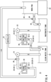
FIG. 4 is a schematic view showing a configuration of theelectrical discharge machine 10 according to a third modification. InFIG. 4 , the same components as those described in the embodiment and the first modification are denoted by the same reference numerals. It should be noted that, in the present modification, descriptions that are duplicative of those given in the embodiment will be omitted. - In the present modification, a work-
pan 40 is newly provided. The work-pan 40 is a tank that stores a dielectric working fluid for immersing a workpiece. The work-pan 40 is installed on the upper surface of aninstallation base 42. In the case of the present modification, thefirst conduit 20 is formed so that the clean water flows to the work-pan 40 through thesludge filter 26. Specifically, the downstream portion 20-2 of thefirst conduit 20 guides the clean water flowing out from thesludge filter 26 to the work-pan 40. In the present modification as well, the resistivity of the clean water can be improved as in the first modification. - In addition, in the present modification, a
third conduit 44 is connected to the work-pan 40. Thethird conduit 44 guides the dielectric working fluid stored in the work-pan 40 to thewastewater tank 14. An on-offvalve 46 is provided in thethird conduit 44. The on-offvalve 46 is configured to be able to switch between opening and closing thethird conduit 44. When the on-offvalve 46 is opened, thethird conduit 44 is opened. When the on-offvalve 46 is closed, thethird conduit 44 is closed. The opening and closing of the on-offvalve 46 are executed by thecontroller 32. - The
controller 32 opens the on-offvalve 46 at a predetermined timing such as when the machining of the workpiece is finished, and discharges the dielectric working fluid stored in the work-pan 40 to thewastewater tank 14. In this case, thecontroller 32 may open the on-offvalve 28 and drive thefirst pump 18 to supply, to the work-pan 40, the clean water in an amount corresponding to the amount of the dielectric working fluid discharged to thewastewater tank 14. This can suppress a significant increase in the ion concentration of the dielectric working fluid stored in the work-pan 40, and as a result, can suppress a decrease in the machine accuracy. - The
resistivity meter 30 may be replaced by a conductivity meter. The conductivity meter measures the conductivity of the clean water stored in theclean water tank 16 and outputs a signal indicating the conductivity to thecontroller 32. In the present modification, thecontroller 32 compares the conductivity measured by the conductivity meter with a predetermined threshold. Further, in the present modification, in a case where the conductivity is equal to or higher than the predetermined threshold, thecontroller 32 drives thefirst pump 18 and opens the on-offvalve 28. The present modification is not limited to being applied to the embodiment, and can be applied to any of the first to third modifications. - The
controller 32 may control an inverter that drives thefirst pump 18 to adjust the flow rate of the clean water in thefirst conduit 20. In this case, the on-offvalve 28 may be removed. In addition, in a case where the on-offvalve 28 is a solenoid valve whose opening degree can be adjusted, thecontroller 32 may adjust the flow rate of the clean water in thefirst conduit 20 by controlling the opening degree of the on-offvalve 28. The present modification is not limited to being applied to the embodiment, and can be applied to any of the first to third modifications. - The
sludge filter 26 may be provided in theclean water tank 16. The present modification is not limited to being applied to the embodiment, and can be applied to any of the first to third modifications. - The invention and effects that can be grasped from the above description will be described below.
-
- (1) The present invention is characterized by the electrical discharge machine (10) for machining the workpiece disposed in the dielectric working fluid by electrical discharge, the electrical discharge machine including: the wastewater tank (14) configured to store wastewater which is the dielectric working fluid containing machining chips generated by machining of the workpiece; the clean water tank (16) configured to store clean water which is the dielectric working fluid obtained by removing the machining chips from the wastewater; the first conduit (20) configured to guide the clean water pumped up from the clean water tank; and the sludge filter (26) which is a porous body including pores through which the clean water supplied from the first conduit passes, the machining chips being trapped in the pores.
According to this feature, the clean water from which the machining chips have been removed is intentionally caused to pass through the pores in which the machining chips are trapped, whereby the resistivity of the clean water can be increased. Therefore, the resistivity of the clean water can be improved without using a generally used ion exchange resin. As a result, the resistivity of the dielectric working fluid can be efficiently improved. - (2) The electrical discharge machine according to the present invention may further include the second conduit (24) configured to guide the dielectric working fluid from the wastewater tank to the clean water tank, and the filtration filter (36) provided in the second conduit and configured to remove the machining chips from the wastewater, wherein the sludge filter may be separate from the filtration filter. According to this feature, the resistivity of the clean water can be improved while removing the machining chips from the wastewater.
- (3) In the electrical discharge machine according to the present invention, the first conduit may be formed in a manner so that the clean water flows through the sludge filter to the clean water tank. According to this feature, the resistivity of the clean water stored in the clean water tank can be stabilized.
- (4) In the electrical discharge machine according to the present invention, the first conduit may be formed in a manner so that the clean water flows through the sludge filter to the wastewater tank. According to this feature, the resistivity of the wastewater stored in the wastewater tank can be stabilized.
- (5) In the electrical discharge machine according to the present invention, the first conduit may be formed in a manner so that the clean water flows through the sludge filter to the work-pan (40) configured to store the dielectric working fluid for immersing the workpiece. According to this feature, the resistivity of the dielectric working fluid stored in the work-pan can be stabilized. As a result, it is possible to suppress a decrease in machine accuracy due to a significant increase in the ion concentration of the dielectric working fluid.
- (6) The electrical discharge machine according to the present invention may further include the second conduit configured to guide the dielectric working fluid from the wastewater tank to the clean water tank, wherein the sludge filter may be provided in the second conduit, and the first conduit may guide the clean water to the sludge filter. According to this feature, the sludge filter for increasing the resistivity of the clean water can be used also as a filtration filter. As a result, the resistivity of the dielectric working fluid can be efficiently improved.
- (7) In the electrical discharge machine according to the present invention, the sludge filter may be the porous body that has been used for removing the machining chips. According to this feature, the filtration filter can be recycled as the sludge filter.
- (8) In the electrical discharge machine according to the present invention, the machining chips may contain at least one of iron, aluminum, copper, zinc, tungsten carbide, tungsten, molybdenum, carbon, titanium, silicon, manganese, chromium, phosphorus, sulfur, and nickel. According to this feature, the resistivity of the clean water can be appropriately increased.
- (9) The electrical discharge machine according to the present invention may further include the resistivity meter (30) configured to measure a resistivity of the clean water, the pump (18) configured to pump up the clean water from the clean water tank, and the controller (32) configured to control the pump to cause the pump to pump up the clean water in a case where the resistivity is equal to or less than a predetermined threshold. According to this feature, an increase in the ion concentration of the clean water can be reliably suppressed.
- The present invention is not limited to the above disclosure, and various modifications are possible without departing from the essence and gist of the present invention.
-
- 10:
- electrical discharge machine
- 14:
- wastewater tank
- 16:
- clean water tank
- 18:
- first pump
- 20:
- first conduit
- 22:
- second pump
- 24:
- second conduit
- 26:
- sludge filter
- 28, 46:
- on-off valve
- 30:
- resistivity meter
- 32:
- controller
- 34, 38:
- filter container
- 36:
- filtration filter
- 40:
- work-pan
Claims (9)
- An electrical discharge machine (10) for machining a workpiece disposed in a dielectric working fluid by electrical discharge, the electrical discharge machine comprising:a wastewater tank (14) configured to store wastewater which is the dielectric working fluid containing machining chips generated by machining of the workpiece;a clean water tank (16) configured to store clean water which is the dielectric working fluid obtained by removing the machining chips from the wastewater;a first conduit (20) configured to guide the clean water pumped up from the clean water tank; anda sludge filter (26) which is a porous body including pores through which the clean water supplied from the first conduit passes, the machining chips being trapped in the pores.
- The electrical discharge machine according to claim 1, further comprising:a second conduit (24) configured to guide the dielectric working fluid from the wastewater tank to the clean water tank; anda filtration filter (36) provided in the second conduit and configured to remove the machining chips from the wastewater, whereinthe sludge filter is separate from the filtration filter.
- The electrical discharge machine according to claim 2, wherein
the first conduit is formed in a manner so that the clean water flows through the sludge filter to the clean water tank. - The electrical discharge machine according to claim 2, wherein
the first conduit is formed in a manner so that the clean water flows through the sludge filter to the wastewater tank. - The electrical discharge machine according to claim 2, wherein
the first conduit is formed in a manner so that the clean water flows through the sludge filter to a work-pan (40) configured to store the dielectric working fluid for immersing the workpiece. - The electrical discharge machine according to claim 1, further comprising a second conduit configured to guide the dielectric working fluid from the wastewater tank to the clean water tank, whereinthe sludge filter is provided in the second conduit, andthe first conduit guides the clean water to the sludge filter.
- The electrical discharge machine according to any one of claims 2 to 6, wherein
the sludge filter is the porous body that has been used for removing the machining chips. - The electrical discharge machine according to any one of claims 1 to 7, wherein
the machining chips contain at least one of iron, aluminum, copper, zinc, tungsten carbide, tungsten, molybdenum, carbon, titanium, silicon, manganese, chromium, phosphorus, sulfur, and nickel. - The electrical discharge machine according to any one of claims 1 to 8, further comprising:a resistivity meter (30) configured to measure a resistivity of the clean water;a pump (18) configured to pump up the clean water from the clean water tank; anda controller (32) configured to control the pump to cause the pump to pump up the clean water in a case where the resistivity is equal to or less than a predetermined threshold.
Applications Claiming Priority (1)
| Application Number | Priority Date | Filing Date | Title |
|---|---|---|---|
| PCT/JP2022/025144 WO2023248434A1 (en) | 2022-06-23 | 2022-06-23 | Electrical discharge machine |
Publications (2)
| Publication Number | Publication Date |
|---|---|
| EP4523826A1 true EP4523826A1 (en) | 2025-03-19 |
| EP4523826A4 EP4523826A4 (en) | 2026-05-06 |
Family
ID=89379300
Family Applications (1)
| Application Number | Title | Priority Date | Filing Date |
|---|---|---|---|
| EP22947995.1A Pending EP4523826A4 (en) | 2022-06-23 | 2022-06-23 | Spark EDM MACHINE |
Country Status (5)
| Country | Link |
|---|---|
| EP (1) | EP4523826A4 (en) |
| JP (1) | JPWO2023248434A1 (en) |
| CN (1) | CN119365286A (en) |
| TW (1) | TW202400333A (en) |
| WO (1) | WO2023248434A1 (en) |
Family Cites Families (6)
| Publication number | Priority date | Publication date | Assignee | Title |
|---|---|---|---|---|
| JPH03221322A (en) * | 1988-10-11 | 1991-09-30 | Taiyo Kogyo Kk | Electric discharging method and device |
| US5434381A (en) * | 1993-09-13 | 1995-07-18 | T-Star Industrial Electronics, Inc. | Apparatus for filtering machining liquid of an electrical discharge machine |
| JP2005219201A (en) * | 2004-01-08 | 2005-08-18 | Nikuni:Kk | Liquid treatment system for wire cut electrical discharge machining |
| JP2013132735A (en) | 2011-12-27 | 2013-07-08 | Fanuc Ltd | Wire electric discharge machine dissolving inert gas in machining fluid and wire electric discharge machining method |
| JP2016055372A (en) * | 2014-09-08 | 2016-04-21 | ファナック株式会社 | Electric discharge machine provided with life decision function of ion exchanger |
| JP2017042899A (en) * | 2015-08-29 | 2017-03-02 | 株式会社橋本テクニカル工業 | Electric discharge processing liquid treatment apparatus, manufacturing method of electric discharge processing product and electric discharge processing apparatus |
-
2022
- 2022-06-23 WO PCT/JP2022/025144 patent/WO2023248434A1/en not_active Ceased
- 2022-06-23 EP EP22947995.1A patent/EP4523826A4/en active Pending
- 2022-06-23 JP JP2024528215A patent/JPWO2023248434A1/ja active Pending
- 2022-06-23 CN CN202280097012.3A patent/CN119365286A/en active Pending
-
2023
- 2023-06-20 TW TW112123026A patent/TW202400333A/en unknown
Also Published As
| Publication number | Publication date |
|---|---|
| WO2023248434A1 (en) | 2023-12-28 |
| TW202400333A (en) | 2024-01-01 |
| CN119365286A (en) | 2025-01-24 |
| EP4523826A4 (en) | 2026-05-06 |
| JPWO2023248434A1 (en) | 2023-12-28 |
Similar Documents
| Publication | Publication Date | Title |
|---|---|---|
| JP2015196225A (en) | Wire electrical discharge machine | |
| CN211414557U (en) | Water tank for machining center | |
| WO2023248434A1 (en) | Electrical discharge machine | |
| JP5727562B2 (en) | EDM machine filter | |
| TWI713993B (en) | Electric discharge machine | |
| JP7438039B2 (en) | cutting fluid tank | |
| TWI884317B (en) | Life-time estimation device and machine tool | |
| CN116000395A (en) | Water circulation system and control method for wire electric discharge cutting machine | |
| CN211170910U (en) | Silicon steel pickling waste acid discharge pipeline cleaning device | |
| EP4559608A1 (en) | Electric discharge machining device | |
| CN102655973A (en) | Corrosion prevention device, corrosion prevention method, and wire electrodischarge machining apparatus | |
| EP4631659A1 (en) | Device for treating water for machining | |
| EP4717389A1 (en) | Liquid filtration device and processing system | |
| JP5796504B2 (en) | Control method of slurry supply apparatus | |
| CN213049696U (en) | Vortex filter filtration system | |
| JP7711156B2 (en) | Coolant tanks and machine tools | |
| JPWO2023248434A5 (en) | ||
| JP2026008822A (en) | filtration device | |
| WO2024262006A1 (en) | Electric discharge machining machine | |
| WO2023248435A1 (en) | Adjustment device, adjustment method, and manufacturing method | |
| WO2024247147A1 (en) | Control device and treatment system for liquid filtration device | |
| CN120479065A (en) | Filtering device and filtering method for waste cutting fluid | |
| EP0442119A2 (en) | Method and apparatus for treating the dielectric used in electrical discharge machining | |
| CN121100038A (en) | Control device, electric discharge machine, and control method | |
| GB1592720A (en) | Electrolytic methodfor breaking an oil-inwater emulsion |
Legal Events
| Date | Code | Title | Description |
|---|---|---|---|
| STAA | Information on the status of an ep patent application or granted ep patent |
Free format text: STATUS: THE INTERNATIONAL PUBLICATION HAS BEEN MADE |
|
| PUAI | Public reference made under article 153(3) epc to a published international application that has entered the european phase |
Free format text: ORIGINAL CODE: 0009012 |
|
| STAA | Information on the status of an ep patent application or granted ep patent |
Free format text: STATUS: REQUEST FOR EXAMINATION WAS MADE |
|
| 17P | Request for examination filed |
Effective date: 20241211 |
|
| AK | Designated contracting states |
Kind code of ref document: A1 Designated state(s): AL AT BE BG CH CY CZ DE DK EE ES FI FR GB GR HR HU IE IS IT LI LT LU LV MC MK MT NL NO PL PT RO RS SE SI SK SM TR |
|
| DAV | Request for validation of the european patent (deleted) | ||
| DAX | Request for extension of the european patent (deleted) | ||
| A4 | Supplementary search report drawn up and despatched |
Effective date: 20260402 |
|
| RIC1 | Information provided on ipc code assigned before grant |
Ipc: B23H 1/10 20060101AFI20260327BHEP |