EP4523800A1 - Dosiersystem und verfahren zur steuerung eines dosiersystems - Google Patents
Dosiersystem und verfahren zur steuerung eines dosiersystems Download PDFInfo
- Publication number
- EP4523800A1 EP4523800A1 EP24210318.2A EP24210318A EP4523800A1 EP 4523800 A1 EP4523800 A1 EP 4523800A1 EP 24210318 A EP24210318 A EP 24210318A EP 4523800 A1 EP4523800 A1 EP 4523800A1
- Authority
- EP
- European Patent Office
- Prior art keywords
- actuator
- dosing system
- pressure
- dosing
- ejection element
- Prior art date
- Legal status (The legal status is an assumption and is not a legal conclusion. Google has not performed a legal analysis and makes no representation as to the accuracy of the status listed.)
- Pending
Links
Images




Classifications
-
- B—PERFORMING OPERATIONS; TRANSPORTING
- B05—SPRAYING OR ATOMISING IN GENERAL; APPLYING FLUENT MATERIALS TO SURFACES, IN GENERAL
- B05B—SPRAYING APPARATUS; ATOMISING APPARATUS; NOZZLES
- B05B1/00—Nozzles, spray heads or other outlets, with or without auxiliary devices such as valves, heating means
- B05B1/24—Nozzles, spray heads or other outlets, with or without auxiliary devices such as valves, heating means incorporating means for heating the liquid or other fluent material, e.g. electrically
-
- B—PERFORMING OPERATIONS; TRANSPORTING
- B05—SPRAYING OR ATOMISING IN GENERAL; APPLYING FLUENT MATERIALS TO SURFACES, IN GENERAL
- B05B—SPRAYING APPARATUS; ATOMISING APPARATUS; NOZZLES
- B05B1/00—Nozzles, spray heads or other outlets, with or without auxiliary devices such as valves, heating means
- B05B1/30—Nozzles, spray heads or other outlets, with or without auxiliary devices such as valves, heating means designed to control volume of flow, e.g. with adjustable passages
- B05B1/3033—Nozzles, spray heads or other outlets, with or without auxiliary devices such as valves, heating means designed to control volume of flow, e.g. with adjustable passages the control being effected by relative coaxial longitudinal movement of the controlling element and the spray head
- B05B1/304—Nozzles, spray heads or other outlets, with or without auxiliary devices such as valves, heating means designed to control volume of flow, e.g. with adjustable passages the control being effected by relative coaxial longitudinal movement of the controlling element and the spray head the controlling element being a lift valve
- B05B1/3046—Nozzles, spray heads or other outlets, with or without auxiliary devices such as valves, heating means designed to control volume of flow, e.g. with adjustable passages the control being effected by relative coaxial longitudinal movement of the controlling element and the spray head the controlling element being a lift valve the valve element, e.g. a needle, co-operating with a valve seat located downstream of the valve element and its actuating means, generally in the proximity of the outlet orifice
- B05B1/306—Nozzles, spray heads or other outlets, with or without auxiliary devices such as valves, heating means designed to control volume of flow, e.g. with adjustable passages the control being effected by relative coaxial longitudinal movement of the controlling element and the spray head the controlling element being a lift valve the valve element, e.g. a needle, co-operating with a valve seat located downstream of the valve element and its actuating means, generally in the proximity of the outlet orifice the actuating means being a fluid
-
- B—PERFORMING OPERATIONS; TRANSPORTING
- B05—SPRAYING OR ATOMISING IN GENERAL; APPLYING FLUENT MATERIALS TO SURFACES, IN GENERAL
- B05C—APPARATUS FOR APPLYING FLUENT MATERIALS TO SURFACES, IN GENERAL
- B05C11/00—Component parts, details or accessories not specifically provided for in groups B05C1/00 - B05C9/00
- B05C11/10—Storage, supply or control of liquid or other fluent material; Recovery of excess liquid or other fluent material
- B05C11/1002—Means for controlling supply, i.e. flow or pressure, of liquid or other fluent material to the applying apparatus, e.g. valves
- B05C11/1034—Means for controlling supply, i.e. flow or pressure, of liquid or other fluent material to the applying apparatus, e.g. valves specially designed for conducting intermittent application of small quantities, e.g. drops, of coating material
-
- B—PERFORMING OPERATIONS; TRANSPORTING
- B05—SPRAYING OR ATOMISING IN GENERAL; APPLYING FLUENT MATERIALS TO SURFACES, IN GENERAL
- B05C—APPARATUS FOR APPLYING FLUENT MATERIALS TO SURFACES, IN GENERAL
- B05C5/00—Apparatus in which liquid or other fluent material is projected, poured or allowed to flow on to the surface of the work
- B05C5/02—Apparatus in which liquid or other fluent material is projected, poured or allowed to flow on to the surface of the work the liquid or other fluent material being discharged through an outlet orifice by pressure, e.g. from an outlet device in contact or almost in contact, with the work
- B05C5/0225—Apparatus in which liquid or other fluent material is projected, poured or allowed to flow on to the surface of the work the liquid or other fluent material being discharged through an outlet orifice by pressure, e.g. from an outlet device in contact or almost in contact, with the work characterised by flow controlling means, e.g. valves, located proximate the outlet
- B05C5/0237—Fluid actuated valves
-
- G—PHYSICS
- G01—MEASURING; TESTING
- G01F—MEASURING VOLUME, VOLUME FLOW, MASS FLOW OR LIQUID LEVEL; METERING BY VOLUME
- G01F11/00—Apparatus requiring external operation adapted at each repeated and identical operation to measure and separate a predetermined volume of fluid or fluent solid material from a supply or container, without regard to weight, and to deliver it
- G01F11/02—Apparatus requiring external operation adapted at each repeated and identical operation to measure and separate a predetermined volume of fluid or fluent solid material from a supply or container, without regard to weight, and to deliver it with measuring chambers which expand or contract during measurement
- G01F11/08—Apparatus requiring external operation adapted at each repeated and identical operation to measure and separate a predetermined volume of fluid or fluent solid material from a supply or container, without regard to weight, and to deliver it with measuring chambers which expand or contract during measurement of the diaphragm or bellows type
Definitions
- the invention relates to a dosing system for dosing a liquid to viscous dosing substance, preferably for applying the dosing substance to a substrate, and to a method for controlling such a dosing system.
- Dosing systems of the type mentioned above are used in a wide variety of applications to precisely dose a medium, typically a liquid to viscous dosing substance.
- a medium typically a liquid to viscous dosing substance.
- microwavesing technology it is often necessary to deliver very small amounts of the medium to a target surface with high precision, i.e., at the right time, in the right place, and in a precisely measured amount.
- Dosing is often contactless, i.e., without direct contact between the dispensing system and the target surface. This can be achieved, for example, by dispensing the dispensing substance dropwise via a nozzle of the dispensing system.
- the medium only comes into contact with the interior of the nozzle and a, usually front, area of an ejection element of the dispensing system.
- the size of the droplets or the amount of medium per droplet can be predicted as precisely as possible through the design and control of the nozzle, as well as the resulting effect.
- Such a contactless process is often referred to as a "jet process."
- a typical example is the dispensing of adhesive dots, solder pastes, etc., when assembling printed circuit boards or other electronic components, or the application of converter materials for LEDs.
- a movable ejection element can be arranged in the nozzle of the dosing system.
- the ejection element can be pushed forward inside the nozzle at a relatively high speed toward a nozzle opening or outlet opening, whereby a drop of the medium is ejected and then retracted again.
- the ejection element For ejection from the nozzle, the ejection element comes into contact with the dosing material to be dispensed and "pushes” or “pushes” the dosing material out of the nozzle of the dosing system due to a movement of the ejection element and/or the nozzle.
- the ejection element thus effectively "actively” ejects the dosing substance from the nozzle.
- This distinguishes such dosing systems, including the dosing system according to the invention, from other dispenser systems in which the movement of a closure element merely opens the nozzle, with the pressurized dosing substance then exiting the nozzle on its own. This is the case, for example, with injection valves in internal combustion engines.
- the ejection element can also be moved into a closed position by firmly connecting it to a sealing seat in the nozzle opening and temporarily remaining there.
- an actuator unit of the dosing system can, in principle, be implemented in various ways, e.g., using a pneumatically or hydraulically operated actuator. Alternatively, piezoelectric and/or electromagnetically operated actuators are also used. Compared to the previously mentioned actuator principles, an actuator unit with a pneumatic or hydraulic actuator is characterized by a comparatively simple design, which also reduces the overall complexity of the dosing system. Therefore, pneumatic or hydraulic actuators represent a cost-effective solution for the operation of dosing systems, especially when processing easy-to-dose dosing materials.
- Pneumatic or hydraulic actuators can be implemented in various ways. For example, dosing systems are known in which the actuator is implemented using a pneumatic or hydraulic cylinder. Since such systems experience comparatively high wear in the area of the cylinder's friction seals, pneumatic or hydraulic actuators are increasingly being used, which are implemented using a bellows that can be pressurized with a pressure medium.
- Another preferred alternative is to design the pneumatic or hydraulic actuator using a diaphragm that can be pressurized with a pressure medium.
- This variant offers the advantage that, on the one hand, friction seals, such as those found in pneumatic or hydraulic cylinders, can be dispensed with.
- the design and manufacturing effort can be reduced compared to "bellows-operated" actuators.
- diaphragm-operated pneumatic or hydraulic actuators can be operated at a higher clock frequency than is typically the case with bellows-operated or cylinder-operated actuators. Therefore, diaphragm-operated pneumatic or hydraulic actuators are particularly suitable for extremely precise dosing requirements.
- a deflectable diaphragm of the actuator is firmly connected to the ejection element of the dosing system.
- the ejection element can be permanently welded, riveted, screwed, soldered, or glued to the diaphragm. It is also possible for the ejection element to completely penetrate the diaphragm and be firmly screwed to the diaphragm on at least one side surface, or to be firmly connected to the diaphragm by means of a retaining ring or pin. The aforementioned methods can achieve a firm coupling between the ejection element and the diaphragm.
- the diameter of the diaphragm can be increased to increase the diaphragm's acceleration force.
- an increase in the diaphragm diameter also results in the volume of the actuator chamber of the pneumatic or hydraulic actuator, which is filled with pressure medium to deflect the diaphragm, having to be increased. Due to the design, however, this also makes the filling or emptying process of the actuator chamber more time-consuming, unnecessarily slowing the cycle frequency of the dosing system.
- the diaphragm can be significantly weakened due to the rigid connection of the ejection element to the diaphragm.
- the connection point between the ejection element and the diaphragm in particular, can therefore develop a weak point in the diaphragm, similar to a predetermined breaking point, which can be problematic, especially during continuous operation of the dosing system. This can significantly shorten the service life or operating time of the pneumatic actuator, which can result in increased maintenance effort and thus higher operating costs for the dosing system.
- a dosing system for dosing a liquid to viscous dosing substance, in particular for the preferably contactless application of a dosing substance to a substrate, comprises a housing, optionally consisting of several parts, wherein the housing comprises at least one nozzle and a feed channel for the dosing substance.
- the dosing substance to be dosed enters a nozzle chamber of this nozzle via the feed channel of the dosing system.
- the dosing system further comprises an ejection element, which is movably arranged in the housing, as well as an actuator unit coupled or interacting with the ejection element for dispensing the dosing substance.
- the actuator unit interacts with the ejection element in such a way that the dosing substance is dispensed from the nozzle of the dosing system by means of the ejection element.
- Such an ejection element thus "actively" ejects the dosing substance, as explained above in the introductory part of the application.
- the dosing system can preferably be implemented in the manner of a jet valve, whereby the dosing substance can be dispensed contactlessly, as explained above.
- the actuator unit comprises at least one actuator with a membrane, preferably of disc-shaped design as explained below, which can also be referred to as an "actuating membrane.”
- the actuator comprises only a single membrane.
- the actuator unit may also include additional components required to move the ejection element in the dosing system, as explained later.
- components of the dosing system that come into contact with the dosing substance, e.g., the ejection element may preferably be combined in a fluidic unit of the dosing system, as will also be explained later.
- the actuator's membrane in particular a side surface of the membrane facing away from the ejection element, can be acted upon by at least one pressure medium such that the ejection element is moved or deflected in an ejection direction of the ejection element to eject the dosing substance from the nozzle.
- the pressure medium particularly the one in motion, strikes or impacts directly on the side surface (top side) of the membrane facing away from the ejection element. This means that the membrane is deflected directly by the pressure medium itself to eject dosing substance from the nozzle.
- the ejection element is moved by means of the membrane toward an outlet opening of the nozzle.
- the movement can occur such that a tip of the ejection element directly rests against a sealing seat of the nozzle upon completion of the ejection movement.
- the ejection movement can also be stopped beforehand, so that a distance remains between the tip of the ejection element and the sealing seat of the nozzle.
- the ejection element is formed separately from the membrane, i.e., it is a component separate from the membrane itself.
- the ejection element is formed as a single piece.
- the ejection element is pressed into an operative position during operation of the dosing system by means of a force acting directly on the ejection element by means of contact pressure against a side surface of the membrane facing in the direction of the ejection element.
- the side surface of the membrane intended for coupling thus faces away from the side surface of the membrane that can be subjected to pressure medium.
- the two side surfaces of the membrane correspond in terms of their design to a base surface of the membrane, as explained later.
- the side surface facing the ejection element or nozzle is usually directed downwards when the dosing system is used as intended (since the dosing system is usually arranged in such a way that the dosing agent is dispensed downwards from the nozzle) and is therefore also referred to below, without limitation, as the "underside” of the diaphragm.
- the side surface of the diaphragm opposite the underside, which can be subjected to pressure medium, is accordingly referred to as the "top side" of the diaphragm.
- the force is only exerted on the ejection element itself, not directly on the membrane but only indirectly via the ejection element, ie at least part of the Force is transmitted from the ejection element to the membrane due to the coupling.
- the ejection element is designed separately, i.e., the ejection element is not firmly or permanently connected to the membrane.
- no form fit or material bond is required between the respective components to couple the ejection element to the actuator unit or the membrane of the actuator. Rather, the coupling is based on the principle of frictional connection.
- the ejection element can be continuously held in operative contact with the side surface of the membrane facing towards the ejection element during operation of the dosing system. Only if the force acting on the ejection element for coupling is missing or falls below a certain value do the ejection element and the membrane again form two uncoupled, independent components.
- the ejection element is therefore held to the membrane in a "non-penetrating" and “damage-free” manner.
- This means that the ejection element is not, for example, screwed, welded, glued, etc. to the membrane.
- the coupling process essentially involves no change to the surface finish of the membrane's underside and/or top side.
- the dosing system advantageously ensures that only very small masses have to be moved by the actuator of the actuator unit during operation of the dosing system.
- This allows the overall weight of the actuating membrane to be kept as low as possible, while also allowing the volume of the actuator chamber for actuating the membrane to be kept small.
- This design accelerates the filling and emptying process of the actuator chamber, allowing the actuator to achieve very high dynamic values.
- the dosing system is therefore also suitable for dosing highly viscous dosing substances despite its comparatively simple design.
- the dosing system according to the invention can almost completely avoid any design-related weakening of the membrane material, as is often the case with conventional dosing systems in the area of the fixed connection between the membrane and the ejection element.
- the actuator can also be designed to Seals, such as those required for pneumatic or hydraulic cylinders, can be dispensed with.
- the dosing system according to the invention can therefore extend the uninterrupted service life of the actuator and thus also of the entire dosing system, while simultaneously enabling very high cycle frequencies for dosing material delivery.
- the dosing system has a housing, optionally consisting of several parts, wherein the housing comprises at least one nozzle and a feed channel for the dosing substance.
- the housing has an ejection element, which is movably arranged in the housing, and an actuator unit coupled to or interacting with the ejection element for dispensing the dosing substance.
- a pressure medium is applied to an (actuating) membrane of an actuator of the actuator unit in order to move or deflect the ejection element in an ejection direction of the ejection element for ejecting the dosing substance from the nozzle.
- a side surface of the membrane facing away from the ejection element also called the "top side” is subjected to the pressure medium in order to move the ejection element toward a nozzle.
- a force is exerted on the ejection element itself.
- the ejection element By means of the force acting on the ejection element, the ejection element is pressed or pressed against a side surface of the membrane facing in the direction of the ejection element (also called the "bottom side") by means of contact pressure.
- the force can be exerted on the ejection element in such a way that the ejection element is continuously held in operative contact with the membrane during operation of the dosing system, in particular with the side surface of the membrane facing in the direction of the ejection element.
- the dosing system is preferably designed such that the force acting on the ejection element, e.g., a plunger, for coupling is directed opposite to an ejection direction, i.e., a direction of ejection movement, of the ejection element.
- the ejection direction corresponds to the (linear) movement of the ejection element for dispensing the dosing substance from the nozzle.
- the ejection direction is therefore directed from the coupling point (between the ejection element and the diaphragm) toward the nozzle of the dosing system.
- a force can preferably be exerted on the ejection element such that an (effective) direction of the force points away from the nozzle and is aligned substantially perpendicular to a base surface of the actuator's diaphragm.
- a retraction movement An opposite movement of the ejection element, also known as a "ram,” i.e., a movement away from the nozzle, is referred to as a retraction movement. Accordingly, the retraction movement occurs in a retraction direction of the ejection element, as explained below.
- the dosing system can be designed such that, during operation, the ejection element is permanently pressed against the underside of the membrane facing the ejection element by means of a force applied by at least one spring and/or pressure arrangement for coupling to the actuator unit.
- the force exerted by the spring and/or pressure arrangement is, in particular, large enough to continuously hold the ejection element in direct contact with the underside of the membrane even during a retraction movement of the ejection element, i.e., when the ejection element is moved away from the nozzle toward the actuator unit after the dosing substance has been dispensed.
- the spring and/or pressure arrangement can simply consist of a spring arrangement comprising several springs or other resilient components. In the simplest and therefore often preferred case, it can consist of a single resilient component, e.g., a single spring, in particular a helical spring. For the sake of simplicity (without limiting its generality), the spring arrangement will also be referred to below as a spring or "return spring.” Alternatively or additionally, the spring and/or pressure arrangement can also comprise pressure elements of other forms, such as pneumatic pressure cylinders, another diaphragm device, or the like.
- the return spring can be designed to move the ejection element, in particular as soon as the membrane is no longer subjected to pressure medium, within a to a rest position within a specific time interval.
- the rest position of the ejection element is characterized by the fact that the greatest possible distance (during operation) is achieved between a tip of the ejection element and the nozzle, i.e., the ejection element is pressed upwards as far as possible toward the actuator unit by the spring.
- the ejection element rests directly against the underside of the membrane even in a rest position.
- the return spring can also exert a "return effect" on the diaphragm.
- the diaphragm can preferably be designed such that it automatically returns to a rest position within a certain time interval as soon as the diaphragm is no longer subjected to pressure medium, i.e., the diaphragm can be designed to be elastic
- the forces exerted by the return spring can at least support the elastic properties of the diaphragm, i.e., the spring can facilitate the diaphragm's return to its rest position.
- the return spring can therefore preferably be designed to transmit a force to the diaphragm (indirectly via the ejection element), whereby the force preferably acts away from the nozzle in the direction of the actuator unit and can preferably be determined such that the return spring pushes the diaphragm (indirectly) upwards by a certain amount and/or even brings the diaphragm into a rest position.
- the rest position of the diaphragm is present when the diaphragm is not currently subjected to pressure medium and/or is not deflected toward the nozzle.
- the diaphragm or diaphragm wall can extend essentially in one plane in the rest position, i.e., it has a substantially straight or linear cross-section.
- the diaphragm prefferably be curved "upward" at least in sections in the rest position, i.e., toward the actuator unit, e.g., by the diaphragm being pushed upwards by the ejection element.
- the force acting on the ejection element for coupling can, as mentioned, act in such a way that the ejection element directly abuts the underside of the membrane even in the rest position, while maintaining the aforementioned essentially linear cross-sectional profile of the membrane.
- the spring can also be dimensioned and/or configured such that the ejection element (in a rest position) pushes or deflects the membrane (in a rest position) by a certain amount upwards in the direction of the actuator unit.
- the membrane can, in a rest position, at least partially abut directly against a base body of the actuator.
- the actuator's diaphragm can preferably be disk-shaped.
- a disk is generally understood to be a geometric body or structure whose base area is many times larger than its thickness.
- the base area corresponds to the area of the diaphragm with the largest surface area.
- the base area thus corresponds, on the one hand, to the side surface of the diaphragm facing the tappet and, on the other hand, to the (opposite) side surface of the diaphragm that can be subjected to pressure medium.
- the thickness of a diaphragm corresponds to the extent of the diaphragm orthogonal to its base area, with the thickness resulting, for example, from a section perpendicular to the base area (cross-section).
- the diaphragm can preferably have a constant, uniform thickness across its entire extent.
- an edge region of the diaphragm (in cross-section) can be thinner than a central region of the diaphragm. This can increase the stiffness of the diaphragm in the central region, for example where the ejection element of the diaphragm is in contact, whereby the diaphragm is deflected predominantly in the edge region when subjected to a pressure medium. This can increase the effective area of the diaphragm and thus the force generated by the diaphragm.
- the diaphragm could have a bead in an edge region, as is the case with loudspeakers, for example.
- the diaphragm prefferably be corrugated in cross-section, e.g., like a corrugated sheet, whereby the spring rate and thus the restoring force of the diaphragm are reduced compared to a "non-corrugated" or flat diaphragm.
- the following assumes a flat diaphragm with a uniform thickness that has a predominantly straight cross-section in a resting position.
- the thickness of the membrane can be at least 10 ⁇ m, preferably at least 50 ⁇ m, and preferably at least 150 ⁇ m.
- the maximum thickness of the membrane can be at most 1000 ⁇ m, preferably at most 300 ⁇ m, and preferably at most 200 ⁇ m.
- the base area of the membrane can be substantially round or circular. However, it can also be elliptical, rectangular, or any other shape. It is preferred that the membrane be designed as a flat or thin, i.e., a "plate-like" structure.
- the membrane is particularly preferably void-free, i.e., there are no cavities inside the membrane, such as liquid-filled and/or gas-filled chambers. This distinguishes a membrane from a bellows, e.g., a metal bellows, due to its construction.
- a bellows comprises a more or less elastic tube that folds together in an accordion-like manner, and an interior space within it that is sealed from the environment, e.g., a cavity that can be filled with gas.
- the membrane is preferably made entirely of metal.
- the membrane can comprise a mixture of different metals or an alloy.
- the membrane can be made of stainless steel (spring steel).
- the membrane can comprise, for example, a copper-beryllium alloy.
- elastomers or plastics are also conceivable as membrane materials.
- a membrane can have a special coating on its top and/or bottom.
- the membrane can be designed to have high vibration resistance and a certain elasticity to enable a desired deflection of the membrane.
- the membrane is designed to represent an "active" expansion element relative to a rigid base body of the actuator, as explained below.
- the membrane in particular an edge region of the membrane, is sealed around its entire circumference to a rigid, possibly multi-part, base body of the actuator.
- This creates an actuator chamber of the actuator which can be pressurized with a pressure medium, between the actuator base body and the membrane, in particular its upper side.
- the membrane can be welded or soldered to the base body, for example.
- the membrane can also be clamped to the actuator base body, for example, by sealingly clamping the membrane between two housing parts of the actuator base body.
- the actuator chamber is therefore located within the actuator itself.
- the actuator chamber can preferably be designed to be gas-tight and/or liquid-tight with respect to the actuator's surroundings.
- the actuator base body preferably comprises an opening (hereinafter referred to as a "bore” without limitation of generality) on a side opposite the membrane, which leads from the actuator chamber to the outside of the actuator chamber in order to to enable control of the actuator.
- a control valve of the actuator unit can be located directly adjacent to the bore to control the flow of the pressure medium through the bore, i.e., to "open” and "close” the actuator chamber, as explained below.
- the actuator is implemented using a single diaphragm, so that only this single diaphragm needs to be sealed to the actuator body.
- This allows for a structural simplification of the dosing system, especially compared to "bellows-operated” systems. In the latter, the bellows or hose typically needs to be sealed at two opposite ends.
- a pressure medium can be supplied to the actuator chamber, e.g., via the previously mentioned bore.
- an overpressure can be generated in the actuator chamber to deflect the diaphragm from a rest position downwards, i.e., toward the nozzle of the dosing system.
- the level of the overpressure can be specified and can be determined, for example, by the nature (e.g., viscosity) of the dosing material.
- the overpressure could be in the range of approximately 5 bar to 8 bar. However, significantly higher pressures are also possible, as explained later.
- the diaphragm can also be referred to as a pressure diaphragm, whereby the diaphragm is designed to transmit a force to the plunger and simultaneously seal the actuator chamber. Furthermore, the actuator chamber can also be emptied again via the same bore, i.e., the overpressure in the actuator chamber is reduced, whereby the diaphragm is returned to a preferably vertical rest position due to its elasticity and/or by means of the return spring.
- the actuator chamber can in principle be filled with any flowing fluid, i.e., (compressed) gaseous and/or liquid substances can be used as the pressure medium.
- a compressed gaseous fluid can be used as the pressure medium, e.g., a single gas or a gas mixture, e.g., air.
- the actuator is also referred to synonymously as a pneumatic actuator in the context of this application.
- the invention is not intended to be limited to this.
- the above-mentioned bore of the actuator chamber preferably borders directly, in particular gas- and/or liquid-tight, to the control valve of the actuator unit.
- the control valve is preferably designed to control and/or regulate the supply of pressure medium into the actuator chamber and the discharge of pressure medium from the actuator chamber.
- the control valve is preferably coupled to a control and/or regulating unit of the dosing system.
- the control valve can be implemented, for example, by means of a solenoid valve.
- the control valve can be implemented by means of a 3/2-way valve (e.g., normally open).
- the control valve could also comprise, for example, two 2/2-way valves.
- the control valve can also be referred to as a pneumatic valve.
- control valve can be arranged in the actuator unit such that a first connection (working connection) of the control valve interacts (gas-tight) with the bore of the actuator chamber, whereby the actuator chamber can be filled with pressure medium and also emptied again by means of this connection.
- a second connection (compressed air connection) of the control valve is functionally coupled to a compressed air supply of the dosing system.
- a third connection (venting connection) of the control valve can be coupled to a venting area of the actuator unit, as explained later.
- the working connection can interact with either the compressed air connection or the venting connection, depending on the control valve control.
- This pressure tank can preferably be separated or insulated from other housing areas in the dosing system housing.
- the pressure tank can comprise at least one supply opening for pressure medium into the pressure tank and one discharge opening for pressure medium out of the pressure tank, in particular for supply to the control valve.
- the pressure tank can preferably be dimensioned such that it can contain a sufficient quantity of pressure medium for at least 250, preferably at least 2000, particularly preferably at least 10,000 deflections of the diaphragm.
- the pressure of the pressure medium in the pressure reservoir can preferably be at least 2 bar, preferably at least 3 bar, and particularly preferably at least 5 bar.
- the pressure should preferably be at most 1000 bar, particularly preferably at most 20 bar, and most particularly preferably at most 10 bar.
- the pressure tank can be coupled to an external compressed air supply of the dosing system.
- a compressed pressure medium can be supplied to the pressure reservoir via the supply opening, e.g., by connecting an external pressure medium supply to a corresponding coupling point in the dosing system housing.
- a preset pressure target pressure
- the pressure reservoir can be located inside the housing directly adjacent to the control valve of the actuator unit.
- the pressure reservoir is preferably arranged in the housing of the dosing system so that the pressure medium can flow from the pressure tank directly into the actuator chamber via the shortest possible route.
- the pressure reservoir can be located as close to the "demand point" as possible.
- the discharge opening of the pressure tank is preferably directly coupled (gas-tight) to the compressed air connection of the control valve.
- the pressure reservoir therefore represents an internal "pressure medium buffer" within the dosing system to dampen the pulsed consumption of pressure medium, especially at high dosing frequencies.
- Dosing systems with pneumatic actuators typically have an external pressure tank for this purpose.
- line losses can cause a drop in the pressure medium pressure on the way from the external pressure tank to the actuator, preventing the actuator chamber from being filled with the desired, particularly constant, pressure.
- the pressure with which the actuator is filled also referred to as the actuator filling pressure—can have a significant influence on the dosing accuracy of the dosing system and may even adversely affect it, as explained later.
- the "pressure medium buffer” is located in close proximity to the actuator, eliminating the need for a line between the pressure tank and the actuator chamber. This ensures that the actuator chamber is always filled with a pressure medium at a specific target pressure, even at very high cycle frequencies. As already mentioned, this has a positive effect on dosing accuracy.
- this design also allows for significantly higher cycle frequencies than conventional dosing systems with pneumatic actuators, since even at very high cycle frequencies, no line losses occur between the pressure tank and the pneumatic actuator. While dosing frequencies of up to approximately 330 Hz were previously possible, The described design enables dispensing frequencies of 600 Hz and more. In principle, the internal "pressure medium buffer” also allows for even higher clock frequencies (>700 Hz), although in this respect, the control valve represents the speed-limiting factor due to heat generation.
- a housing-internal pressure reservoir in the immediate vicinity of the actuator is not limited to the above-mentioned dosing system according to the invention. Rather, this advantageous design represents an independent aspect of the invention.
- an internal pressure reservoir can therefore also be arranged in dosing systems with a pneumatic cylinder or in conventional "bellows-operated” or “diaphragm-operated” dosing systems, i.e., also in dosing systems in which, for example, an ejection element is firmly connected to a diaphragm of the pneumatic actuator, i.e., independently of the coupling according to the invention.
- a dosing system can comprise a housing comprising a nozzle and a feed channel for dosing material, an ejection element movably mounted in the housing, and an actuator unit coupled to the ejection element.
- the actuator unit can comprise an actuator with a diaphragm that can be acted upon by a pressure medium in order to move the ejection element in an ejection direction.
- the housing of the dosing system can comprise an internal pressure reservoir for the pressure medium.
- the reservoir can be directly adjacent to a control valve of the actuator unit for controlling the actuator.
- the dosing system may preferably comprise, in addition to the internal pressure tank, another, possibly larger, external pressure tank, e.g., in the external pressure medium supply.
- the concept of the internal pressure tank can be profitably supplemented by arranging at least one pressure sensor in the pressure reservoir in such a way that a pressure of the The pressure medium in the pressure reservoir is measured.
- the pressure sensor could be implemented in a wall of the pressure tank.
- the pressure sensor is preferably arranged as close as possible to the pneumatic actuator.
- the pressure sensor can preferably be coupled to the control and/or regulating unit of the dosing system for transmitting measurement data.
- the control and/or regulating unit can either be designed as a direct component of a dosing system or be implemented separately from the dosing system.
- a third possibility is for the control and/or regulating unit to be designed separately and assigned to multiple dosing systems simultaneously in order to control them separately from one another.
- open-loop control is used below as a synonym for open-loop and/or closed-loop control. This means that even when referring to open-loop control, the open-loop control can at least comprise a control process.
- closed-loop control a controlled variable (as the actual value) is generally continuously recorded and compared with a reference variable (as the setpoint). Typically, the control is carried out in such a way that the controlled variable is adjusted to the reference variable. This means that the controlled variable (actual value) continuously influences itself within the control loop.
- the dosing system can comprise at least one controllable pressure regulator.
- the pressure regulator is preferably designed to control and/or regulate the pressure of the pressure medium in the pressure reservoir as a function of an input parameter, preferably by controlling and/or regulating the pressure of a pressure medium flowing into the housing of the dosing system or into the reservoir.
- the pressure in the pressure reservoir i.e. the pressure present upstream of the control valve, is also referred to as the actuator supply pressure.
- the supply pressure determines the maximum pressure with which the actuator chamber can be filled, i.e. the maximum pressure the pressure medium can have when flowing into the actuator chamber.
- the supply pressure can also correspond to an actuator filling pressure.
- the actuator filling pressure corresponds to the pressure that the pressure medium actually has in the (filled) actuator chamber, e.g. during a deflection of the diaphragm.
- the pressure regulator can preferably also be designed to To control and/or regulate the pressure with which the actuator is filled with pressure medium (actuator filling pressure) depending on an input parameter.
- the pressure regulator can be operated mechanically or manually.
- an input parameter can then be transmitted to an operator of the dosing system, who then adjusts the pressure regulator so that a target pressure is reached in the pressure reservoir.
- an electronic pressure regulator can also be used.
- the pressure regulator can be controlled by the control and/or regulating unit of the dosing system, in particular taking input parameters into account.
- the pressure regulator can preferably be arranged on the housing of the dosing system and/or in an external pressure medium supply line.
- the (mechanical or electronic) pressure regulator can be controlled or regulated depending on an input parameter in such a way that a specific, e.g., a constant, speed of the ejection element (ram speed) is achieved during the ejection movement during operation of the dosing system.
- a specific, e.g., a constant, speed of the ejection element (ram speed) is achieved during the ejection movement during operation of the dosing system.
- An input parameter of the control or regulation system can, for example, be the current pressure in the pressure reservoir.
- the measurement data from the pressure sensor can be continuously compared with a predefined setpoint value as input parameters (actual values) by the control and/or regulation unit during operation.
- the pressure regulator is then preferably controlled in such a way that a setpoint pressure is continuously maintained in the internal pressure tank or a constant ram speed is achieved during operation.
- the dosing accuracy of the dosing system can be further improved by using the pressure sensor and the internal pressure reservoir in conjunction with the control and/or regulating unit.
- a key factor for the amount of dosing material ejected per ram stroke is the ram speed, particularly when impacting the nozzle or its sealing seat. Therefore, the ram speed (during the ejection movement) can preferably be adjusted to a setpoint, possibly constant, during operation. The ram speed depends significantly on the actuator filling pressure.
- a higher actuator filling pressure results in a higher acceleration force of the diaphragm, which leads to a higher plunger speed.
- a lower actuator filling pressure correspondingly leads to a slower plunger speed during the ejection process. Therefore, pressure fluctuations during the filling process of the actuator chamber can have a negative impact on dosing accuracy.
- the plunger speed can be set to a predefined value and kept constant during operation, for example, in order to further increase dosing accuracy even with very dynamic and/or high dosing requirements. For example, pressure fluctuations in the supply line could be compensated for using this control or regulation.
- the dosing system can include at least one sensor for measuring the speed of a movement of the ejection element.
- a speed sensor can preferably be arranged in a region of the rigid actuator base body.
- the sensor can preferably be arranged in a region of the actuator base body opposite the top side of the membrane, i.e., "above” the membrane.
- the speed sensor and the ejection element e.g., a plunger head, can preferably be arranged on an imaginary (vertical) line.
- the speed sensor is preferably coupled to the control unit.
- the speed sensor is preferably designed to detect the speed of the ejection element during the entire ejection movement and/or the entire retraction movement of the ejection element.
- the speed sensor can be implemented using a position sensor (stroke sensor) designed to detect a plunger position as a function of time.
- the speed sensor can preferably be implemented using a Hall sensor.
- a "head region" of the ejection element that rests against the membrane can then preferably comprise a magnet.
- the speed sensor could comprise a capacitive distance sensor.
- the distance sensor and the membrane (as a movable counter surface) could form an electrical capacitor, e.g., by designing the membrane in the manner of a capacitor plate.
- the dosing system e.g., the control valve
- the throttle device can be designed to control and/or regulate a pressure of the pressure medium in the actuator, in particular in the actuator chamber, as a function of an input parameter.
- the throttle device can preferably be designed to dynamically control and/or regulate a pressure in the actuator, in particular as a function of an input parameter.
- the throttle can alternatively or additionally be designed or controlled in such a way that the inflow of pressure medium into the actuator chamber is completely interrupted at a specific time.
- the proportional valve in the working port could be (completely) closed as soon as a specific pressure is present in the actuator chamber during filling.
- the throttle can be controlled in such a way that a specific, e.g., a maximum permissible, pressure in the actuator chamber is not exceeded during operation. This can, under certain circumstances, lead to the pressure of the filled actuator (for deflection of the diaphragm) is lower than the supply pressure.
- the dosing system can be equipped with a pressure sensor to measure the pressure in the actuator chamber.
- the throttle device can be implemented using a mechanical or manual throttle.
- at least one input parameter can be transmitted to an operator of the dosing system, whereby the operator then adjusts the throttle (which could also be referred to as an expansion valve) such that a specific (target) flow through the throttle and thus a desired plunger speed is achieved during the ejection movement of the plunger.
- the throttle which could also be referred to as an expansion valve
- the throttle device can preferably be implemented by means of an electronic throttle, e.g., a proportional valve.
- the throttle can preferably be controlled by the control unit as a function of an input parameter, e.g., an actual plunger speed, such that a specific volume flow or a desired pressure in the actuator chamber is achieved.
- the throttle device can be controlled such that a specific pressure in the actuator, in particular during filling, is not exceeded.
- the throttle device can be controlled as a function of at least one input parameter such that a, e.g., constant, predeterminable plunger speed is achieved during the ejection movement and/or retraction movement.
- controllable throttle device allows the ram speed to be set to a constant value during the ejection movement during operation.
- the controllable throttle device thus represents a second alternative or additional variant for keeping the ram speed constant during operation and thus further improving dosing accuracy.
- a previously described throttle device which is designed to control and/or regulate a pressure in the actuator as a function of an input parameter, preferably by means of a control and/or regulating unit of a dosing system, is not limited to the aforementioned dosing system according to the invention, but represents an independent aspect of the invention.
- a dosing system of conventional design with a pneumatic actuator e.g., with a pneumatic cylinder or a fixed connection between the ejection element and the diaphragm, can also have such a throttle device.
- the dosing system can be designed to set a specific speed profile of the ejection element during a respective ejection movement and/or the retraction movement.
- the dynamic control of the speed of the ejection element is also referred to as flank control.
- the dosing system preferably the control valve, can comprise at least one throttle device designed to control and/or regulate a pressure curve during filling of the actuator with pressure medium and/or during emptying or venting of the actuator.
- the control and/or regulation can take place as a function of at least one input parameter.
- the throttle device can preferably be configured to adjust a flow rate of the fluid flowing through it by locally (variably) constricting a flow cross-section so that a filling process of the actuator chamber can be temporally controlled.
- the throttle can be used to temporally control the pressure increase in the actuator chamber (temporal control of the pressure curve).
- the throttle can preferably be configured to dynamically control or regulate the flow rate during a respective ejection movement and/or during a respective retraction movement of the ejection element.
- the throttle device can be controlled such that the pressure increase in the actuator chamber occurs dynamically or variably, i.e., the pressure in the actuator chamber does not increase constantly or linearly.
- the pressure curve here refers to the pressure in the actuator, in particular in the actuator chamber, as a function of time (during filling or venting).
- the throttle device can be controlled such that the speed of the plunger varies during the ejection movement, i.e., the plunger has two or more different speeds or is accelerated to two or more different speeds during a single ejection movement.
- the speed of the plunger can be controlled and/or regulated throughout the entire plunger movement, i.e., from the rest position to impact with the nozzle.
- the throttle device can be implemented by means of a controllable proportional valve.
- a controllable proportional valve For the highest possible resolution control of the speed profile of the plunger during the ejection process, at least one, for example, piezo-operated actuator with a variable flow rate can preferably be used.
- the electronically controllable piezo-operated actuator is preferably part of the throttle device and can be controlled by the control unit in order to regulate the volume flow (flow rate) of the fluid flowing into the actuator.
- the pressure medium and/or the pressure medium flowing out of the actuator can be controlled essentially without delay.
- control valve could be designed such that, by means of the actuator, a flow cross-section of the working connection of the control valve (e.g., a 3/2-way valve or two 2/2-way valves) can be controlled (changed) essentially in real time during the inflow and/or outflow of pressure medium into or out of the actuator.
- a flow cross-section of the working connection of the control valve e.g., a 3/2-way valve or two 2/2-way valves
- control valve could comprise two separately controllable proportional valves instead of a 3/2-way valve, thus simultaneously implementing a throttle device.
- a first proportional valve could be used for the (time-controlled) filling of the actuator chamber, and a second proportional valve for the (time-controlled) venting of the actuator chamber.
- the two proportional valves could use the same or different bores in the actuator chamber. This allows the pressure curve during filling and venting to be controlled separately.
- An input parameter on which the control is based can be, for example, a measurement signal from the speed sensor.
- a predeterminable speed profile of the plunger can also serve as an input parameter, which is created, for example, depending on the nature of the dosing material and/or the dosing requirement and can be stored in the control unit.
- the control unit can then preferably control (adjust) the pressure during filling of the actuator depending on the actual speed of the plunger so that a desired speed profile is achieved during the ejection process.
- the throttle device could be controlled such that the plunger, starting from its rest position, is initially accelerated by the diaphragm to a very high speed (strong inflow of pressure medium into the actuator, i.e., rapid pressure increase in the actuator chamber) in order to achieve shearing of the dosing material.
- the plunger speed could then be reduced (reduced inflow of pressure medium into the actuator, i.e., slower pressure increase in the actuator chamber) in order to achieve clean ejection of the dosing material from the nozzle.
- the dosing system can be controlled, particularly by means of a throttle device configured in this way, to control the pressure curve and/or the time curve of the actuator filling.
- a throttle device configured in this way, to control the pressure curve and/or the time curve of the actuator filling.
- This allows a desired speed curve of the plunger movement to be achieved during each phase of the ejection movement. (also referred to as flank control).
- This can advantageously further improve dispensing accuracy, particularly by effectively compensating for external factors.
- fluctuations in the dispensing medium can be compensated for, for example, due to batch-dependent factors (viscosity), temperature-dependent factors, or material age (curing processes in adhesives).
- small manufacturing tolerances or wear processes can also be compensated for by controlling the flanks.
- the throttle device can also be designed or controlled in such a way as to control the pressure curve and/or the temporal progression of the emptying even when the actuator is vented.
- the plunger can have two or more different speeds or a defined speed curve during the retraction movement.
- the control can preferably be carried out as a function of an input parameter, e.g. measurement data from the speed sensor, in order to achieve a predeterminable speed profile of the plunger.
- a retraction speed of the plunger can be determined such that no air is sucked through the nozzle opening during the retraction movement, whereby the formation of air bubbles in a drop of the dosing substance subsequently ejected from the nozzle can be avoided.
- a control and/or regulation of the pressure curve during the filling or emptying of the actuator chamber preferably by means of the throttle device, such that a speed of the ejection element is varied during an ejection movement and/or during a retraction movement, is not limited to the above-mentioned dosing system according to the invention, but represents an independent partial aspect of the invention.
- a dosing system of conventional design with a pneumatic actuator e.g. with a pneumatic cylinder or a fixed connection between the ejection element and the membrane, can also have a throttle device as explained above, whereby such (known) dosing systems can also be operated with a desired speed profile of the plunger movement.
- the dosing system can also be designed to increase the uninterrupted operating time of the dosing system.
- the actuator unit can be designed to use the pressure medium flowing out of the actuator or from the actuator chamber as a cooling medium for cooling the control valve.
- the venting or emptying of the Actuator chamber is preferably vented by means of the vent connection of the control valve, whereby the vent connection opens into a vent area of the actuator unit.
- the control valve e.g. a solenoid valve
- the venting area is therefore preferably designed as a cavity in the housing of the dosing system so that it encloses or surrounds the entire control valve from the outside.
- the pressure medium can preferably be guided past the control valve in such a way that as much heat as possible is dissipated from a surface of the control valve by means of the pressure medium.
- the pressure medium e.g. compressed room air, is hardly heated as a result of the passage of the actuator and can therefore be used as a cooling medium.
- the venting area which could also be referred to as the cooling area, thus forms a cooling device for the dosing system with the pressure medium.
- the housing can have a bore to discharge the pressure medium from the venting area.
- the pressure medium could be actively cooled to a specific temperature before entering the housing, for example, using a cooling device. This would allow the control valve to be permanently kept below a critical operating temperature.
- active cooling could be controlled, for example, by the control valve incorporating a temperature sensor and transmitting corresponding measured values to the control unit. The control unit could then control the cooling device depending on the measured values so that the cooling device provides a correspondingly cooled pressure medium to keep the temperature of the control valve below a critical value.
- this cooling system ensures that the control valve is reliably kept below a critical operating temperature during operation, thereby improving the reliability of the dosing system. This allows the dosing system to be operated even at high outside temperatures. Furthermore, the cycle frequencies of the dosing system can be increased compared to conventional dosing systems, since sufficient heat energy can be dissipated from the control valve even at very high cycle frequencies.
- a pressure that essentially corresponds to a cartridge pressure pressure of the dosing agent in a dosing agent cartridge
- the tappet seal encloses the tappet and is implemented as part of the fluidic unit of the dosing system.
- the tappet seal is located opposite an outlet opening of the nozzle, with the tappet seal defining the upper limit of a nozzle chamber.
- a negative pressure particularly a vacuum
- a vacuum can be maintained between the actuator diaphragm, preferably its underside, and the tappet seal.
- This can advantageously increase the performance of the actuator or dosing system, as the vacuum facilitates or supports the deflection of the diaphragm toward the nozzle.
- This can be particularly advantageous for media that are difficult to dose, such as dosing materials with high viscosity.
- the pressure of the pressure medium flowing into the housing of the dosing system or into the internal pressure tank is preferably controlled and/or regulated by the pressure regulator of the dosing system as a function of at least one input parameter such that the speed of the ejection element during an ejection movement, in particular upon impact with the nozzle, corresponds to a desired value.
- the pressure regulator is preferably controlled by the control unit of the dosing system.
- the pressure of the pressure medium flowing into the actuator or actuator chamber and/or the pressure of the pressure medium flowing out of the actuator or actuator chamber is controlled and/or regulated by the throttle device of the dosing system as a function of at least one input parameter such that the speed of the ejection element during a respective ejection movement and/or retraction movement corresponds to a setpoint.
- the control unit of the dosing system can continuously receive measured values from at least one sensor during operation, e.g., from the speed sensor, in order to perform a real-time comparison of the measured values (actual value) with a predeterminable setpoint.
- the throttle device is then preferably controlled such that the pressure medium flows into or out of the actuator with such a volume flow to achieve a desired plunger speed during the ejection movement and/or the retraction movement.
- control unit can control the throttle device such that a speed of the ejection element is varied during a single ejection movement and/or during a single retraction movement.
- the ejection element can be accelerated to two or more different speeds for a single respective movement.
- control unit can control the flow rate of the pressure medium through the throttle device as a function of at least one input parameter, e.g., speed measurement data, such that a specific speed profile of the plunger is achieved during the ejection and/or retraction movement.
- the expansion valve can be controlled such that the actuator is first filled with a first pressure for a (single) ejection movement in order to achieve a first ejection speed, and then filled with a second, different pressure in order to achieve a second ejection speed, which can differ from the first ejection speed.
- the expansion valve or throttle can also be used in a conventional dosing system. This can then be used, for example, to control and/or regulate the pressure of the pressure medium in such a way that the speed of the ejection element is varied during an ejection movement and/or during a retraction movement.
- the control method makes it possible to operate a dosing system, independent of the specific connection of the ejection element to the diaphragm, in such a way that a desired speed profile of the plunger movement is achieved.
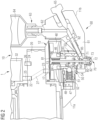
- FIG. 1 A concrete embodiment of a dosing system 1 according to the invention will now be described.
- the dosing system 1 is shown here in section in the position customary in the intended operation of the dosing system 1.
- a nozzle 70 is located in the lower area of the dosing system 1, so that the drops of the medium are ejected downwards through the nozzle 70 in an ejection direction RM.
- bottom and top are used below, these details therefore always refer to such a usually customary position of the dosing system 1.
- the dosing system 1 can also be used in a different position in special applications and the drops can be ejected, for example, laterally Depending on the medium, pressure, and precise design and control of the entire ejection system, this is generally possible.
- the dosing system 1 comprises, as essential components, an actuator unit 10 and a fluidic unit 60 coupled thereto.
- the dosing system 1 shown here further comprises a dosing substance cartridge 64, which is coupled to the fluidic unit 60.
- the actuator unit 10 and the fluidic unit 60 are designed as plug-in coupling parts that can be coupled together to form a quick-action coupling.
- the actuator unit 10 and the fluidic unit 60 can thus be coupled together without tools to form the dosing system 1.
- the quick-action coupling comprises a coupling mechanism 50 with a coupling spring 51 that keeps a ball 52 constantly pre-tensioned.
- the coupling spring 51 and the ball 52 are enclosed by a (first) actuator unit housing block 11a and form a first plug-in coupling part. This is particularly evident in Figure 2 which shows a section of the dosing system from Figure 1 in an enlarged view.
- the coupling mechanism 50 has a number of spherical caps 54 (in Figure 2 only one shown), into which the ball 52 can engage for coupling.
- the spherical caps 54 are arranged in a second plug-in coupling part 53 of the fluidic unit 60, wherein the fluidic unit 60 is enclosed by a (second) fluidic unit housing block 11b.
- the first plug-in coupling part (of the actuator unit 10) and the second plug-in coupling part (of the fluidic unit 60) can be plugged into one another along a (virtual or imaginary) plug-in axis and thereby coupled to one another.
- the fluidic unit 60 can be rotated against a direction RM (see Figure 1 ) are inserted into the actuator unit 10 and coupled to the actuator unit 10 in a suitable rotational position.
- the spherical caps 54 are arranged in the second plug-in coupling part 53 of the fluidic unit 60 in such a way that various locking positions are possible, i.e., different rotational positions of the fluidic unit 60 around the plug-in axis are possible.
- the spring-loaded ball 52 engages the plug-in coupling part 53 in one of several possible locking positions, thus forming the dosing system 1.
- the dosing system 1 here comprises a housing 11 with the two mentioned housing parts (housing blocks) 11a and 11b.
- the respective assemblies 10, 60 can also be firmly connected to one another, e.g. by means of a fixing screw, in order to form the housing 11.
- the actuator unit 10 essentially comprises all components that ensure the drive or movement of an ejection element 80, here a plunger 80, in the nozzle 70, i.e., for example, a pneumatic actuator 12 in order to be able to actuate the ejection element 80 of the fluidic unit 60, a control valve 20, a control unit (in Figures 1 and 2 not shown) to control the pneumatic actuator 12 and similar components, as explained below.
- the fluidic unit 60 includes all other parts that are in direct contact with the medium, as well as the elements required to assemble the respective parts in contact with the medium or to hold them in position on the fluidic unit 60. Furthermore, the fluidic unit 60 also includes means for returning the ejection element 80 to a rest position or starting position after the dosing substance has been dispensed, as will be explained below.
- the actuator unit 10 comprises, as mentioned, a pneumatic actuator 12 which can be pressurised with a pressure medium, here preferably compressed air.
- a pressure medium here preferably compressed air.
- a membrane 13 of the actuator 12 is shown only schematically, i.e. not in a real position or configuration that the membrane 13 actually has during operation during a deflection or retraction. This will be explained later with reference to the Figures 3 and 4 explained.
- the pneumatic actuator 12 ( Figure 1 ) is coupled to the fluidic unit 60 in such a way that by means of a control of the pneumatic actuator 12 the plunger 80 is actuated in such a way that the fluidic unit 60 supplies a medium to be dosed in the desired quantity to the desired time.
- the plunger 80 currently closes a nozzle opening 72 and thus also serves as a closure element 80.
- ejection element 80 since the largest part of the medium is already ejected from the nozzle opening 72 when the plunger 80 is in an ejection direction RA (see Figure 2 ), it is referred to here as ejection element 80.
- the coupling between pneumatic actuator 12 and plunger 80 will be explained later using Figure 3 explained in detail.
- the pneumatic actuator 12 is arranged in the actuator unit 10 in close proximity to a control valve 20 for controlling the actuator 12.
- the control valve 20 e.g., a pneumatic 3/2-way valve, is designed to supply a pressure medium, e.g., compressed room air, to the actuator 12 and/or to discharge a pressure medium from the actuator 12.
- the actuator 12 is arranged in the actuator unit 10 such that a bore 17 of the actuator 12 interacts with a working connection 23 of the control valve 20 or is spatially connected thereto. This is particularly important in Figure 2 clearly.
- the control valve 20 further comprises a compressed air connection 22 and a vent connection 24, wherein, depending on the control or switching position of the control valve 20, either the compressed air connection 22 or the vent connection 24 interacts or is connected to the working connection 23.
- the control valve 20 is coupled to a circuit board 42 of the dosing system by means of a connecting cable 21 and can be controlled via it by a control unit of the dosing system 1 (e.g., electrically) (see Figure 1 ).
- control valve 20 is arranged in the actuator unit 10 such that the compressed air connection 22 interacts with or is connected to a bore 25 (here top left), wherein the bore 25 and the compressed air connection 22 have essentially the same diameter.
- the bore 25 is implemented here as a discharge opening 25 of an internal pressure reservoir 32 (hereinafter also referred to as pressure tank 32) of the dosing system 1.
- pressure tank 32 an internal pressure reservoir 32
- a pressure medium can be supplied to the control valve 20 (via the compressed air connection 22) and thus subsequently also to the actuator 12 (via the working connection 23 and the bore 17).
- the pressure tank 32 is directly adjacent to the control valve 20. Therefore, no connecting lines are required between the pressure tank 32 and the control valve 20, apart from the bore 25, so that line losses in the pressure medium can be largely prevented.
- the pressure tank 32 extends in the housing block 11a between the discharge opening 25 and a printing medium supply device 30, which comprises a coupling point 31 for an external printing medium supply (not shown) (see Figure 1 ) and represents a cavity or a chamber in the dosing system 1.
- a pressure medium with a specific pressure can be supplied to the pressure reservoir 32 in a direction RD.
- an external pressure medium supply line can additionally comprise a controllable pressure regulator, as will be explained with reference to Figure 7 is explained.
- the pressure tank 32 is designed, in particular in interaction with the pressure medium supply device 30 and the pressure regulator, to maintain a pressure medium DK at a specific pressure during operation (see Figure 6 ).
- the pressure of the pressure medium in the pressure tank 32 corresponds to the supply pressure of the actuator 12.
- the pressure tank 32 here comprises a pressure sensor 33 to determine a pressure of the pressure medium in the pressure tank 32 (see Figure 1 ).
- the pressure sensor 33 is arranged here on a circuit board 42 of the dosing system 1.
- the circuit board 42 can also include or be coupled to various other electronic components, e.g., a temperature sensor 48 or a heating device 47 or a heating element 47.
- the circuit board 42 is connected to a connection device 40, which includes a coupling point 41 for a connection cable of the control unit (not shown). By means of the coupling point 41, e.g., a plug socket, the measurement signals of the pressure sensor 33 or other sensors can be fed to the control unit of the dosing system 1.
- control unit can access the various electrical components of the dosing system 1 by means of the connection device 40, i.e., for example, control the heating device 47. Furthermore, the control unit can also control the control valve 20 by means of the connection device 40, the circuit board 42, and the connection cable 21.
- control valve 20 comprises a venting connection 24, which interacts with or is connected to a bore 26 (here top right) of a venting area 34 of the dosing system 1, wherein the bore 26 and the venting connection 24 have substantially the same diameter.
- a pressure medium can be discharged from the actuator 12 and advantageously used to cool the control valve 20.
- the venting area 34 will be described later with reference to Figure 6 explained in more detail.
- control valve 20 In order to operate the pneumatic actuator 12 in the desired manner, the control valve 20 can be controlled by the control unit of the dosing system 1.
- Figure 1 The control valve 20 shown (hereinafter also referred to as the "pneumatic valve") could, for example, be a pneumatic 3/2-way solenoid valve with a normally open position ("filling" position). Accordingly, in a normal position of the pneumatic valve 20, the pressure medium can be directed from the pressure reservoir 32 via the compressed air connection 22 and a flow channel 27 located in the pneumatic valve 20 (shown here in dashed lines) to the working connection 23.
- the pressure medium flows into an actuator chamber of the actuator 12 at the pressure prevailing in the pressure reservoir 32 (supply pressure) in order to deflect a diaphragm of the actuator 12 and thus the plunger 80 downward in an ejection direction of the plunger 80, whereby a drop of the dosing substance is ejected from the nozzle 70.
- the actuator 12 is filled with the pressure that is present directly upstream of the control valve 20, i.e. the supply pressure of the actuator 12 also corresponds to the actuator filling pressure.
- the supply pressure of the actuator 12 also corresponds to the actuator filling pressure.
- the dosing system 1, e.g. the solenoid valve 20 could be supplemented by one or more controllable actuators with variable throughput, e.g. piezo-operated actuators.
- Such an actuator could, for example, be arranged in the region of the working connection 23 (not shown).
- the pneumatic valve 20 can be switched by the control unit in such a way that the working connection 23 is closed by means of an internal flow channel 27 ⁇ (see Figure 6 ) of the solenoid valve 20 is connected to the vent port 24 (second switching position). Pressure medium then flows into the venting area of the actuator unit 10. This will be shown later using Figure 6 explained.
- the rest position of the actuator 12 is, as stated, when both the diaphragm 13 and the ejection element 80 are in a rest position.
- the diaphragm 13 of the actuator 12 which is not currently pressurized with pressure medium, returns to its rest position due to its inherent tension.
- a plunger head 81 of the plunger 80 is pressed upwards towards the control valve 20 by means of a return spring 84.
- the fluidic unit 60 of the dosing system 1 comprises a second housing part 11b and, as mentioned, is connected to the actuator unit 10 or its housing part 11a by means of a quick coupling to form the housing 11.
- the fluidic unit 60 comprises the plunger 80, which bears directly with a contact surface 86 of the plunger head 81 on a side surface (underside) of the membrane 13 of the actuator 12 facing in the direction of the plunger 80.
- the plunger 80 is here, as is generally preferred in the dosing system, in one piece, i.e. is formed from a single piece.
- the plunger 80 For coupling to the actuator unit 10 (only partially shown), the plunger 80, in particular the plunger head 81, is pressed upwards in the axial direction against the membrane 13 by means of a spring 84.
- the return spring 84 rests on a tappet bearing 83, to which a tappet seal 85 is connected at the bottom.
- the membrane 13 (shown schematically) of the actuator 12 is pressurized with pressure medium (operating position of the actuator 12), so that the plunger tip 82 rests against the sealing seat 73 of the nozzle 70.
- the plunger tip 82 is pushed away from the sealing seat 73 of the nozzle 70 by the return spring 84. The plunger tip 82 is then at a distance from the sealing seat 73 of the nozzle 70, so that the nozzle opening 72 is free or unclosed.
- the supply of dosing material to the nozzle 70 takes place via a nozzle chamber 71, to which a feed channel 62 leads (see Figure 2 ).
- the feed channel 62 is embedded in a fluidic body 61.
- the feed channel 62 is also connected to a dosing agent cartridge 64.
- the feed channel 62 is closed to the outside with a clamping screw 65.
- the dosing agent cartridge 64 is reversibly attached to the housing 11 in the area of a coupling point 63. Furthermore, the cartridge 64 is attached to the actuator unit 10 by means of a holding element 45 (see Figure 1 ).
- the dosing system 1 comprises at least one heating device 47, e.g., one or more heating plates 47 or heating foils 47. This is particularly evident in the enlarged view in Figure 2 clearly.
- the heating device 47 can be controlled by the control unit.
- the heating device 47 is integrated into the actuator unit 10 and initially heats the coupling part of the actuator unit 10, for example, the coupling mechanism 50.
- the plug-in coupling part 53 of the fluidic unit 60 is inserted into the coupling part of the actuator unit 10, the plug-in coupling part 53, in particular the dosing material in the nozzle 70, is heated to a specific temperature.
- the plug-in coupling part 53 is designed to ensure the best possible heat conduction towards the nozzle 70.
- the fluidic unit 60 does not comprise a separate heating device here and can therefore be easily touched or disassembled even during operation.
- the dosing system 1 comprises a plurality of gas-filled cavities 46, 46'.
- the cavities 46, 46' serve to thermally decouple the pneumatic actuator 12 from the fluidic unit 60.
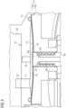
- Figure 3 shows a further enlarged part of the dosing system 1 according to the Figures 1 and 2
- the dosing system 1 is shown here in a different phase of the dosing process.
- the Figures 1 and 2 the dosing system 1 during an ejection process of dosing material from the nozzle.
- the nozzle 70 of the dosing system is ( Figures 1 and 2 ) is closed by the plunger 80.
- Figure 3 a pneumatic actuator 12 in a rest position, ie the membrane 13 of the actuator 12 is not deflected, whereby the ejection element 80 is also in a rest position.
- the nozzle 70 is therefore not closed by the ejection element 80.
- the pneumatic actuator 12 from Figure 3 is in direct operative contact with the working connection 23 of the pneumatic valve 20 via the bore 17.
- the actuator 12 comprises a rigid actuator base body 14, which here is formed by two components 14a, 14b.
- the two components 14a, 14b are arranged relative to one another, preferably in a fixed position, such that they form a hollow space between them in cross-section.
- the two actuator base body parts 14a, 14b rest directly on one another in an outer region of the respective component 14a, 14b and are releasably pressed against one another there, so that the membrane 13 can be replaced if necessary.
- an (actuating) membrane 13 is arranged in a sealed manner between the two rigid base body parts 14a, 14b. It is clear here that the actuator 12 comprises only a single membrane 13 for moving the plunger 80.
- the membrane 13 is shown here in a rest position and is curved upwards in a central region, where the ejection element 80 of the membrane 13 rests.
- the spring 84 or the ejection element 80 presses the membrane 13 against the upper actuator base body 14a, against which the membrane 13 rests at least in part.
- the actuator base body 14a thus limits the stroke or deflection of the membrane 13 upwards.
- the actuator 12 is designed such that the membrane rests at least partially against the upper actuator base body 14a even in a predominantly horizontal rest position, e.g., in that the actuator base body 14a has an extension or bulge pointing in the direction of the membrane 13 in the region of the plunger head 81 (not shown).
- the membrane 13 preferably has a circular base area and is coupled with its edge region completely circumferentially to the two base body parts 14a, 14b of the rigid base body 14 in a gas-tight manner.
- the membrane 13 is pressed in the edge region from below against the upper base body component 14a by means of the lower base body component 14b.
- a sealing ring 15, e.g., an O-ring 15, is arranged between the membrane 13 and the upper component 14a.
- the actuator chamber 16 of the actuator 12 is formed here, as mentioned, between a side surface (top side) of the membrane 13 facing away from the ejection element 80 and the here upper rigid actuator base body part 14a.
- the actuator chamber 16 can be connected to the bore 17 with be filled with a pressure medium in order to deflect the membrane 13 downwards from the rest position shown here. This will be explained later using Figure 4 shown schematically again.
- the plunger head 81 is pressed against the underside 19 of the diaphragm 13 by means of a spring 84.
- the return spring 84 is designed to exert such a (spring) force on the plunger 80 that it is held in direct operative contact with the underside 19 even in a rest position of the actuator 12.
- the plunger 80 presses the diaphragm 13 (at least a central region of the diaphragm 13) upward beyond a horizontal rest position, with the deflection being limited by the component 14a.
- Figure 4 shows a section of a dosing system according to another embodiment.
- the pneumatic actuator 12 here additionally includes a sensor 18 for determining the speed of movement of the ejection element 80.
- the sensor 18 is arranged here in the upper actuator base body part 14a such that it is located on an imaginary vertical line (corresponding to a longitudinal extension of the plunger 80) with the plunger 80.
- the sensor 18 and the plunger head 81 are located directly opposite each other on different sides of the membrane 13.
- the sensor 18 can comprise a position sensor 18 to detect a distance between the sensor 18 and the plunger head 81 as a function of time.
- the sensor 18 can be a Hall sensor, with the plunger head 81 comprising a magnet (not shown).
- the sensor 18 is coupled to the control unit of the dosing system 1 (not shown here).
- the membrane 13 is deformed for the dosing agent delivery.
- the actuator 12 is also shown here in an operating position. This means that the upper side of the diaphragm 13 is currently being pressurized with pressure medium. As can be seen here, the diaphragm 13 is not deflected evenly or uniformly downwards toward the plunger 80 due to the pressurization. Rather, there are areas of the diaphragm 13 that are moved downwards more strongly, and other areas that experience hardly any change in position.
- the edge areas of the diaphragm 13, where the diaphragm 13 is coupled to the actuator base body 14, are barely deflected. Furthermore, the area of the diaphragm 13 that rests on the plunger head 81 is also deflected comparatively little. This is because the plunger 80 is pressed against the underside 19 of the diaphragm 13 by the spring 84.
- the spring 84 therefore opposes the deflection of the diaphragm 13 with a certain force.
- the spring 84 is designed such that the diaphragm 13 overcomes the spring force of the spring 84 during the deflection and deflects the plunger 80 by a desired amount in the direction of the nozzle for dosing substance delivery.
- the central regions of the diaphragm 13, which in the illustrated cross-section lie between the plunger head 81 and the edge region of the diaphragm 13, experience a relatively strong downward deflection.
- the diaphragm 13 is thus deformed in a quasi-wave-like manner during the deflection.
- FIG. 5 shows once again, in a roughly schematic manner, the structure and control of the actuator unit according to an embodiment of the invention.
- the actuator unit 10 comprises an internal pressure reservoir 32 which stores pressure medium at a specific supply pressure.
- the pressure medium is supplied to a control valve 20 in a flow direction RD.
- the control valve 20 is controlled by a control unit (not shown) such that the pressure medium flows in a direction RD' into an actuator chamber 16 of a pneumatic actuator 12.
- an optional throttle device (not shown) can be controlled such that the actuator chamber 16 is filled with pressure medium at a supply pressure or a different actuator filling pressure.
- the membrane 13 and thus also the ejection element 80 are deflected downwards in a direction RA for the discharge of the dosing substance.
- the control valve 20 is controlled by the control unit so that the actuator chamber 16 is vented immediately after the dosing substance has been dispensed.
- the pressure medium leaves the actuator chamber 16 in a flow direction RD" and flows into the control valve 20 before leaving it in a direction RD′′′. Due to the pressure reduction in the actuator chamber 16, the diaphragm 13 swings back to its rest position.
- the ejection element 80 follows the movement of the diaphragm 13 immediately or simultaneously - if necessary, the ejection element 80 even supports the movement of the diaphragm 13 - and is moved back to a rest position by means of a spring 84. This completes one cycle of dosing substance dispensing.
- FIG. 6 shows the dosing system from the Figures 1 to 3 during venting of the pneumatic actuator.
- the control valve 20 is controlled here by the control unit (not shown) such that the working connection 23 interacts with the vent connection 24.
- the control valve 20 is moved into a second switching position so that a flow channel 27' (shown here in dashed lines) connects the two connections 23, 24 inside the control valve 20.
- the pressure medium flows out of the actuator 12 via the bore 17 and is guided through the flow channel 27' to the vent connection 24 and finally into the vent area 34.
- the plunger 80 is pressed upwards away from the nozzle 70 in the direction of the actuator unit 10 by means of the spring 84, so that a small gap forms between the plunger tip 82 and the sealing seat 72 (not shown).
- the membrane 13 is shown here in a horizontal "intermediate position", i.e. the membrane currently returns to a rest position as a result of the venting of the actuator chamber.
- the venting area 34 represents a cavity or chamber within the housing of the actuator unit 10.
- the chamber of the venting area 34 is concealed by the inflowing pressure medium DE.
- the pressure medium in the venting area 34 has a lower pressure than the actuator supply pressure and is therefore referred to as expanded pressure medium DE.
- the venting area 34 borders directly on the control valve 20 via the bore 26 on the one hand and has a bore leading outside the dosing system on the other hand (not shown). As shown here, the venting area 34 encloses a significant portion of the control valve 20 from the outside.
- the venting area 34 is spatially and control-technically separated, in particular, from the pressure tank 32 of the actuator unit 10.
- the pressure tank 32 is filled with a compressed pressure medium DK, with a chamber forming the pressure tank 32 being concealed by the pressure medium DK.
- the pressure medium flowing into the venting area 34 can thus be guided past the control valve, e.g., by means of flow-conducting elements, in order to dissipate as much heat as possible from a surface of the control valve 20.
- the pressure medium e.g., compressed room air
- the pressure of the pressure medium in the venting area 34 can be significantly lower than, e.g., in the pressure reservoir 32 and/or in the actuator chamber.
- FIG. 7 shows a schematic representation of a control method for a dosing system 1 according to one embodiment of the invention.
- the dosing system 1 here comprises a housing 11 in which the essential components of the actuator unit 10 and the fluidic unit are enclosed.
- the dosing system 1 further comprises a control unit 43 with a number of connecting cables 44 for separately controlling the respective components of the dosing system 1.
- the control unit 43 is coupled, on the one hand, to a pressure regulator 35 in order to control and/or regulate the pressure of the pressure medium flowing into the internal pressure tank 32.
- the pressure regulator 35 is coupled to a pressure medium supply 37 and is arranged here as a component of the actuator unit 10, e.g., on the outside of the housing 11 of the dosing system 1.
- An external pressure reservoir 36 is optionally arranged here between the pressure regulator 35 and the internal pressure tank 32.
- the pressure regulator 35 can be controlled by the control unit 43, preferably depending on input parameters, e.g., a ram speed, such that a specific pressure is present in the external pressure tank 36 or the internal pressure tank 32 in order to achieve a constant ram speed during the ejection process.
- control unit 43 can, on the other hand, control the control valve 20 to fill the actuator chamber of the actuator 12 (using the pressure medium from the internal pressure tank 32) or vent it (using a pressure medium outlet DA).
- the actuator 12 of the dosing system 1 is coupled to a sensor 18, e.g., a position sensor 18, with the measurement data being transmitted to the control unit 43 as input parameters.
- the control unit 43 can process these and other input parameters, e.g., from a pressure sensor in the internal pressure tank 32, and use them to control and/or regulate the ram speed or the ram speed profile ("edge control"). Depending on the measured values, the control unit 43 can, for example, control the pressure regulator 35 so that a specific target pressure of the pressure medium (supply pressure) is present in the internal pressure tank 32 in order to achieve a constant ram speed.
- control unit 43 may comprise a throttle device 28 for regulating the flow of the pressure medium, e.g. with a piezoelectric actuator 28, here in the area of the control valve 20, depending on input parameters in order to achieve a certain ram speed or a desired speed profile during the ejection movement and/or retraction movement of the ram 80.
- a throttle device 28 for regulating the flow of the pressure medium, e.g. with a piezoelectric actuator 28, here in the area of the control valve 20, depending on input parameters in order to achieve a certain ram speed or a desired speed profile during the ejection movement and/or retraction movement of the ram 80.
- the control unit 43 can further control a heating device 47 of the dosing system 1 to heat the dosing substance in the nozzle 70 to a desired temperature.
- the control unit 43 can control and/or regulate the heating device 47 as a function of a measured temperature value, wherein the measured temperature value is determined by means of a temperature sensor 48.
- the control unit 43 can also access a second pressure regulator 35', which controls the pressure of the pressure medium in the dosing agent cartridge 64 (cartridge pressure).
- Figure 8 shows a schematic representation of a speed curve of a possible plunger movement according to one embodiment of the invention.
- the control of the speed curve is also referred to as edge control. It shows a relative position PS of the plunger tip in relation to a relative time t of the ejection process.
- the position PD of the sealing seat of the nozzle in the dosing system is shown here in dashed lines.
- the plunger Before the ejection process begins, at time T 1 , the plunger is in a rest position. This means that the tip of the plunger is at the greatest possible distance from the nozzle, so that the nozzle of the dosing system is not closed.
- the actuator is filled with pressure medium at high pressure, resulting in a high ejection velocity of the plunger.
- a piezoelectric actuator could be fully opened to allow for maximum air flow.
- the plunger's ejection speed is slowed. For example, by reducing the air flow through the pneumatic actuator.
- the plunger tip impacts the nozzle's sealing seat at time T 4 at a lower speed, which can improve dosing accuracy for certain dosing materials.
- control of the flanks is of course also possible during a retraction movement of the ram.
Landscapes
- Physics & Mathematics (AREA)
- Fluid Mechanics (AREA)
- General Physics & Mathematics (AREA)
- Coating Apparatus (AREA)
- Application Of Or Painting With Fluid Materials (AREA)
- Reciprocating Pumps (AREA)
Applications Claiming Priority (3)
| Application Number | Priority Date | Filing Date | Title |
|---|---|---|---|
| DE102018131567.8A DE102018131567A1 (de) | 2018-12-10 | 2018-12-10 | Dosiersystem und Verfahren zur Steuerung eines Dosiersystems |
| EP19813309.2A EP3894093B1 (de) | 2018-12-10 | 2019-11-29 | Dosiersystem und verfahren zur steuerung eines dosiersystems |
| PCT/EP2019/083127 WO2020120176A2 (de) | 2018-12-10 | 2019-11-29 | Dosiersystem und verfahren zur steuerung eines dosiersystems |
Related Parent Applications (2)
| Application Number | Title | Priority Date | Filing Date |
|---|---|---|---|
| EP19813309.2A Division EP3894093B1 (de) | 2018-12-10 | 2019-11-29 | Dosiersystem und verfahren zur steuerung eines dosiersystems |
| EP19813309.2A Division-Into EP3894093B1 (de) | 2018-12-10 | 2019-11-29 | Dosiersystem und verfahren zur steuerung eines dosiersystems |
Publications (1)
| Publication Number | Publication Date |
|---|---|
| EP4523800A1 true EP4523800A1 (de) | 2025-03-19 |
Family
ID=68762745
Family Applications (2)
| Application Number | Title | Priority Date | Filing Date |
|---|---|---|---|
| EP24210318.2A Pending EP4523800A1 (de) | 2018-12-10 | 2019-11-29 | Dosiersystem und verfahren zur steuerung eines dosiersystems |
| EP19813309.2A Active EP3894093B1 (de) | 2018-12-10 | 2019-11-29 | Dosiersystem und verfahren zur steuerung eines dosiersystems |
Family Applications After (1)
| Application Number | Title | Priority Date | Filing Date |
|---|---|---|---|
| EP19813309.2A Active EP3894093B1 (de) | 2018-12-10 | 2019-11-29 | Dosiersystem und verfahren zur steuerung eines dosiersystems |
Country Status (12)
Families Citing this family (6)
| Publication number | Priority date | Publication date | Assignee | Title |
|---|---|---|---|---|
| DE102018131567A1 (de) * | 2018-12-10 | 2020-06-10 | Vermes Microdispensing GmbH | Dosiersystem und Verfahren zur Steuerung eines Dosiersystems |
| US11931752B2 (en) * | 2021-04-08 | 2024-03-19 | Suzhou Hsen-mez Automation Co., Ltd. | Non-contact precision pneumatic injection valve |
| EP4245135A1 (de) | 2022-03-16 | 2023-09-20 | Bayer AG | Durchführen und dokumentieren einer applikation von pflanzenschutzmittel |
| TWI837657B (zh) | 2022-05-06 | 2024-04-01 | 庫力索法高科股份有限公司 | 具二段式校正機構的噴射閥 |
| FR3155272B1 (fr) * | 2023-11-15 | 2025-10-17 | Ridel | Système de génération d’impulsions pour une alimentation en fluide de travail pulsé, et machine industrielle comprenant un tel système |
| DE102024114869A1 (de) * | 2024-05-27 | 2025-11-27 | Vermes Microdispensing GmbH | Pneumatikaktor für ein Dosierventil |
Citations (6)
| Publication number | Priority date | Publication date | Assignee | Title |
|---|---|---|---|---|
| DE1255009B (de) * | 1961-11-10 | 1967-11-23 | Richard Zippel & Co K G | Spritzpistole |
| EP0111850A1 (en) * | 1982-12-16 | 1984-06-27 | Nordson Corporation | Constant pressure intermittent fluid dispenser |
| DE4122594A1 (de) * | 1991-05-23 | 1992-11-26 | E I C Group Gmbh | Vorrichtung zum einstellbaren zufuehren eines fluessigen materials |
| US5467899A (en) * | 1994-02-08 | 1995-11-21 | Liquid Control Corporation | Dispensing device for flowable materials |
| EP2586535A2 (en) * | 2011-10-31 | 2013-05-01 | Nordson Corporation | Pneumatically actuated liquid dispensing valve and method |
| US20160221022A1 (en) * | 2011-08-26 | 2016-08-04 | Nordson Corporation | Modular jetting devices |
Family Cites Families (25)
| Publication number | Priority date | Publication date | Assignee | Title |
|---|---|---|---|---|
| US2335935A (en) * | 1941-08-01 | 1943-12-07 | George C Hanley | Humidifier head |
| US3053461A (en) * | 1959-11-12 | 1962-09-11 | Bruce D Inglis | Pressure controlled spray device |
| US3463363A (en) * | 1967-10-12 | 1969-08-26 | Fusion Inc | Applicator gun |
| DE3925080A1 (de) * | 1989-07-28 | 1991-02-07 | Hesselmann Planatolwerk H | Vorrichtung zur materialversorgung und dosierventil |
| DE19544016A1 (de) * | 1995-11-27 | 1997-05-28 | Klaschka Gmbh & Co | Zerstäubungskopf für Flüssigkeiten sowie Einrichtung zum Besprühen von Werkstücken mit Flüssigkeiten mit solchen Zerstäubungsköpfen |
| DE59802783D1 (de) * | 1997-08-14 | 2002-02-28 | Fischer Georg Rohrleitung | Membranventil |
| EP1155748B1 (en) * | 1998-12-28 | 2017-04-12 | Musashi Engineering, Inc. | Method and device for injecting a fixed quantity of liquid |
| JP2003003952A (ja) * | 2001-06-22 | 2003-01-08 | Noiberuku Kk | 流体吐出装置 |
| US7070066B2 (en) * | 2004-04-08 | 2006-07-04 | Nordson Corporation | Liquid dispensing valve and method with improved stroke length calibration and fluid fittings |
| US20060065868A1 (en) * | 2004-09-28 | 2006-03-30 | Strong Warren N | Diaphragm valve |
| GB2433928B (en) * | 2006-01-07 | 2009-10-14 | Shane Richard Wootton | Apparatus for producing material by a chemical reaction |
| CN102883990B (zh) * | 2009-09-21 | 2015-01-21 | 诺信公司 | 气动致动液体分配阀 |
| DE102010014208A1 (de) | 2010-04-08 | 2011-10-13 | Continental Automotive Gmbh | Verfahren und Vorrichtung zum Betreiben eines Einspritzventils |
| US20130052359A1 (en) | 2011-08-26 | 2013-02-28 | Nordson Corporation | Pneumatically-driven jetting valves with variable drive pin velocity, improved jetting systems and improved jetting methods |
| JP5535155B2 (ja) | 2011-09-05 | 2014-07-02 | 株式会社コガネイ | 流路切換弁およびそれを用いた流動性材料の吐出制御装置 |
| WO2015192896A1 (de) * | 2014-06-18 | 2015-12-23 | Vermes Microdispensing GmbH | DOSIERVENTIL MIT VENTILSTÖßEL |
| US10090453B2 (en) * | 2015-05-22 | 2018-10-02 | Nordson Corporation | Piezoelectric jetting system and method |
| US10105728B2 (en) | 2015-10-15 | 2018-10-23 | The Boeing Company | Systems and apparatuses for applying glutinous substances |
| JP7541919B2 (ja) * | 2017-08-29 | 2024-08-29 | ヘンケル・アクチェンゲゼルシャフト・ウント・コムパニー・コマンディットゲゼルシャフト・アウフ・アクチェン | ゼロ変位シール装置を備えた流体ディスペンサ |
| DE102017122034A1 (de) | 2017-09-22 | 2019-03-28 | Vermes Microdispensing GmbH | Dosiersystem mit Aktoreinheit und lösbar koppelbarer Fluidikeinheit |
| DE102018005910A1 (de) * | 2017-10-20 | 2019-04-25 | Hilger Und Kern Gmbh | Anordnung zum Dosieren eines flüssigen oder pastösen Mediums |
| DE102017126307A1 (de) | 2017-11-09 | 2019-05-09 | Delo Industrie Klebstoffe Gmbh & Co. Kgaa | Dosiervorrichtung sowie Verfahren zum Dosieren von flüssigen Medien |
| DE102018108360A1 (de) * | 2018-04-09 | 2019-10-10 | Vermes Microdispensing GmbH | Dosiersystem mit piezokeramischem Aktor |
| CN112752617B (zh) * | 2018-09-26 | 2023-02-24 | 兵神装备株式会社 | 液体涂敷装置 |
| DE102018131567A1 (de) * | 2018-12-10 | 2020-06-10 | Vermes Microdispensing GmbH | Dosiersystem und Verfahren zur Steuerung eines Dosiersystems |
-
2018
- 2018-12-10 DE DE102018131567.8A patent/DE102018131567A1/de active Pending
-
2019
- 2019-11-29 WO PCT/EP2019/083127 patent/WO2020120176A2/de not_active Ceased
- 2019-11-29 JP JP2021529871A patent/JP7541517B2/ja active Active
- 2019-11-29 EP EP24210318.2A patent/EP4523800A1/de active Pending
- 2019-11-29 SG SG11202102705WA patent/SG11202102705WA/en unknown
- 2019-11-29 CN CN201980078383.5A patent/CN113165005B/zh active Active
- 2019-11-29 US US17/297,893 patent/US12492930B2/en active Active
- 2019-11-29 MY MYPI2021002942A patent/MY200024A/en unknown
- 2019-11-29 ES ES19813309T patent/ES3074787T3/es active Active
- 2019-11-29 EP EP19813309.2A patent/EP3894093B1/de active Active
- 2019-11-29 CA CA3121036A patent/CA3121036A1/en active Pending
- 2019-11-29 KR KR1020257028053A patent/KR20250130714A/ko active Pending
- 2019-11-29 KR KR1020217013043A patent/KR102992875B1/ko active Active
-
2021
- 2021-05-27 PH PH12021551225A patent/PH12021551225A1/en unknown
-
2024
- 2024-06-17 JP JP2024097471A patent/JP7783936B2/ja active Active
Patent Citations (6)
| Publication number | Priority date | Publication date | Assignee | Title |
|---|---|---|---|---|
| DE1255009B (de) * | 1961-11-10 | 1967-11-23 | Richard Zippel & Co K G | Spritzpistole |
| EP0111850A1 (en) * | 1982-12-16 | 1984-06-27 | Nordson Corporation | Constant pressure intermittent fluid dispenser |
| DE4122594A1 (de) * | 1991-05-23 | 1992-11-26 | E I C Group Gmbh | Vorrichtung zum einstellbaren zufuehren eines fluessigen materials |
| US5467899A (en) * | 1994-02-08 | 1995-11-21 | Liquid Control Corporation | Dispensing device for flowable materials |
| US20160221022A1 (en) * | 2011-08-26 | 2016-08-04 | Nordson Corporation | Modular jetting devices |
| EP2586535A2 (en) * | 2011-10-31 | 2013-05-01 | Nordson Corporation | Pneumatically actuated liquid dispensing valve and method |
Also Published As
| Publication number | Publication date |
|---|---|
| ES3074787T3 (es) | 2026-07-23 |
| EP3894093A2 (de) | 2021-10-20 |
| PH12021551225A1 (en) | 2021-12-06 |
| KR102992875B1 (ko) | 2026-07-21 |
| CA3121036A1 (en) | 2020-06-18 |
| CN113165005B (zh) | 2023-05-05 |
| WO2020120176A3 (de) | 2020-08-06 |
| EP3894093C0 (de) | 2026-04-22 |
| JP2024123101A (ja) | 2024-09-10 |
| WO2020120176A2 (de) | 2020-06-18 |
| EP3894093B1 (de) | 2026-04-22 |
| US12492930B2 (en) | 2025-12-09 |
| SG11202102705WA (en) | 2021-04-29 |
| US20220034698A1 (en) | 2022-02-03 |
| JP2022510639A (ja) | 2022-01-27 |
| JP7541517B2 (ja) | 2024-08-28 |
| JP7783936B2 (ja) | 2025-12-10 |
| DE102018131567A1 (de) | 2020-06-10 |
| KR20210100084A (ko) | 2021-08-13 |
| KR20250130714A (ko) | 2025-09-02 |
| CN113165005A (zh) | 2021-07-23 |
| MY200024A (en) | 2023-12-05 |
Similar Documents
| Publication | Publication Date | Title |
|---|---|---|
| EP3894093B1 (de) | Dosiersystem und verfahren zur steuerung eines dosiersystems | |
| EP2969248B1 (de) | Dosierventil und dosierverfahren | |
| EP4013550B1 (de) | Dosiersystem mit justierbarem aktor | |
| EP3860771B1 (de) | Dosiersystem mit kühleinrichtung | |
| EP2734371B3 (de) | Druckkopf für einen tintenstrahldrucker | |
| EP1248927B1 (de) | Additivzerstäubungsvorrichtung | |
| EP3860770B1 (de) | Dosiersystem mit dosierstoff-kühleinrichtung | |
| DE102014013158A1 (de) | Freistrahl-Einrichtung | |
| WO2014048643A1 (de) | Dosiersystem, dosierverfahren und herstellungsverfahren | |
| DE202016008610U1 (de) | Piezoelektrisches Ausstoßsystem | |
| EP3687699B1 (de) | Applikator mit einer dichtungsmembran | |
| EP3902635B1 (de) | Jet-dosierventil | |
| EP3687701B1 (de) | Applikator mit einem geringen düsenabstand | |
| EP4281282B1 (de) | Hydraulische umformmaschine zum pressen von werkstücken, insbesondere schmiedehammer, und verfahren zum betreiben einer hydraulischen umformmaschine, insbesondere eines schmiedehammers | |
| EP3698883A1 (de) | Druckkopf zur applikation eines beschichtungsmittels auf ein bauteil | |
| EP2365883A1 (de) | Für die dosierung von sehr kleinen dosiervolumina geeignete dosiereinrichtung und dosierverfahren | |
| DE112016001582T5 (de) | Tröpfchenabgabevorrichtung | |
| DE102017126307A1 (de) | Dosiervorrichtung sowie Verfahren zum Dosieren von flüssigen Medien | |
| EP2623203B1 (de) | Kapillardispenser | |
| EP2279792B1 (de) | Sprühpistole | |
| EP2945754B1 (de) | Dosiervorrichtung | |
| DE102006019404A1 (de) | Druckregler für gasförmige Medien | |
| EP3896283B1 (de) | Druckkopf mit mikropneumatischer steuereinheit | |
| EP4347141B1 (de) | Dosiersystem | |
| DE102019122276A1 (de) | Die Erfindung betrifft einen Niederhalter für einen Prozess bei Stanzen und/oder Nieten |
Legal Events
| Date | Code | Title | Description |
|---|---|---|---|
| PUAI | Public reference made under article 153(3) epc to a published international application that has entered the european phase |
Free format text: ORIGINAL CODE: 0009012 |
|
| STAA | Information on the status of an ep patent application or granted ep patent |
Free format text: STATUS: THE APPLICATION HAS BEEN PUBLISHED |
|
| AC | Divisional application: reference to earlier application |
Ref document number: 3894093 Country of ref document: EP Kind code of ref document: P |
|
| AK | Designated contracting states |
Kind code of ref document: A1 Designated state(s): AL AT BE BG CH CY CZ DE DK EE ES FI FR GB GR HR HU IE IS IT LI LT LU LV MC MK MT NL NO PL PT RO RS SE SI SK SM TR |
|
| STAA | Information on the status of an ep patent application or granted ep patent |
Free format text: STATUS: REQUEST FOR EXAMINATION WAS MADE |
|
| 17P | Request for examination filed |
Effective date: 20250820 |
|
| STAA | Information on the status of an ep patent application or granted ep patent |
Free format text: STATUS: EXAMINATION IS IN PROGRESS |
|
| 17Q | First examination report despatched |
Effective date: 20260519 |