EP4523765A1 - Anzeigesteuerungsvorrichtung, -verfahren und -programm - Google Patents
Anzeigesteuerungsvorrichtung, -verfahren und -programm Download PDFInfo
- Publication number
- EP4523765A1 EP4523765A1 EP22877667.0A EP22877667A EP4523765A1 EP 4523765 A1 EP4523765 A1 EP 4523765A1 EP 22877667 A EP22877667 A EP 22877667A EP 4523765 A1 EP4523765 A1 EP 4523765A1
- Authority
- EP
- European Patent Office
- Prior art keywords
- captured images
- positional data
- clubhead
- golf club
- toe
- Prior art date
- Legal status (The legal status is an assumption and is not a legal conclusion. Google has not performed a legal analysis and makes no representation as to the accuracy of the status listed.)
- Pending
Links
Images

Classifications
-
- G—PHYSICS
- G06—COMPUTING OR CALCULATING; COUNTING
- G06T—IMAGE DATA PROCESSING OR GENERATION, IN GENERAL
- G06T7/00—Image analysis
- G06T7/70—Determining position or orientation of objects or cameras
-
- G—PHYSICS
- G06—COMPUTING OR CALCULATING; COUNTING
- G06T—IMAGE DATA PROCESSING OR GENERATION, IN GENERAL
- G06T7/00—Image analysis
- G06T7/20—Analysis of motion
- G06T7/246—Analysis of motion using feature-based methods, e.g. the tracking of corners or segments
-
- A—HUMAN NECESSITIES
- A63—SPORTS; GAMES; AMUSEMENTS
- A63B—APPARATUS FOR PHYSICAL TRAINING, GYMNASTICS, SWIMMING, CLIMBING, OR FENCING; BALL GAMES; TRAINING EQUIPMENT
- A63B24/00—Electric or electronic controls for exercising apparatus of preceding groups; Controlling or monitoring of exercises, sportive games, training or athletic performances
- A63B24/0003—Analysing the course of a movement or motion sequences during an exercise or trainings sequence, e.g. swing for golf or tennis
-
- A—HUMAN NECESSITIES
- A63—SPORTS; GAMES; AMUSEMENTS
- A63B—APPARATUS FOR PHYSICAL TRAINING, GYMNASTICS, SWIMMING, CLIMBING, OR FENCING; BALL GAMES; TRAINING EQUIPMENT
- A63B60/00—Details or accessories of golf clubs, bats, rackets or the like
- A63B60/46—Measurement devices associated with golf clubs, bats, rackets or the like for measuring physical parameters relating to sporting activity, e.g. baseball bats with impact indicators or bracelets for measuring the golf swing
-
- A—HUMAN NECESSITIES
- A63—SPORTS; GAMES; AMUSEMENTS
- A63B—APPARATUS FOR PHYSICAL TRAINING, GYMNASTICS, SWIMMING, CLIMBING, OR FENCING; BALL GAMES; TRAINING EQUIPMENT
- A63B69/00—Training appliances or apparatus for special sports
-
- A—HUMAN NECESSITIES
- A63—SPORTS; GAMES; AMUSEMENTS
- A63B—APPARATUS FOR PHYSICAL TRAINING, GYMNASTICS, SWIMMING, CLIMBING, OR FENCING; BALL GAMES; TRAINING EQUIPMENT
- A63B69/00—Training appliances or apparatus for special sports
- A63B69/36—Training appliances or apparatus for special sports for golf
-
- A—HUMAN NECESSITIES
- A63—SPORTS; GAMES; AMUSEMENTS
- A63B—APPARATUS FOR PHYSICAL TRAINING, GYMNASTICS, SWIMMING, CLIMBING, OR FENCING; BALL GAMES; TRAINING EQUIPMENT
- A63B71/00—Games or sports accessories not covered in groups A63B1/00 - A63B69/00
- A63B71/06—Indicating or scoring devices for games or players, or for other sports activities
- A63B71/0619—Displays, user interfaces and indicating devices, specially adapted for sport equipment, e.g. display mounted on treadmills
- A63B71/0622—Visual, audio or audio-visual systems for entertaining, instructing or motivating the user
-
- G—PHYSICS
- G06—COMPUTING OR CALCULATING; COUNTING
- G06F—ELECTRIC DIGITAL DATA PROCESSING
- G06F3/00—Input arrangements for transferring data to be processed into a form capable of being handled by the computer; Output arrangements for transferring data from processing unit to output unit, e.g. interface arrangements
- G06F3/14—Digital output to display device ; Cooperation and interconnection of the display device with other functional units
-
- G—PHYSICS
- G06—COMPUTING OR CALCULATING; COUNTING
- G06N—COMPUTING ARRANGEMENTS BASED ON SPECIFIC COMPUTATIONAL MODELS
- G06N20/00—Machine learning
-
- G—PHYSICS
- G06—COMPUTING OR CALCULATING; COUNTING
- G06T—IMAGE DATA PROCESSING OR GENERATION, IN GENERAL
- G06T11/00—Two-dimensional [2D] image generation
- G06T11/20—Drawing from basic elements
-
- G—PHYSICS
- G06—COMPUTING OR CALCULATING; COUNTING
- G06T—IMAGE DATA PROCESSING OR GENERATION, IN GENERAL
- G06T7/00—Image analysis
- G06T7/10—Segmentation; Edge detection
- G06T7/11—Region-based segmentation
-
- G—PHYSICS
- G06—COMPUTING OR CALCULATING; COUNTING
- G06T—IMAGE DATA PROCESSING OR GENERATION, IN GENERAL
- G06T7/00—Image analysis
- G06T7/70—Determining position or orientation of objects or cameras
- G06T7/73—Determining position or orientation of objects or cameras using feature-based methods
- G06T7/74—Determining position or orientation of objects or cameras using feature-based methods involving reference images or patches
-
- G—PHYSICS
- G06—COMPUTING OR CALCULATING; COUNTING
- G06T—IMAGE DATA PROCESSING OR GENERATION, IN GENERAL
- G06T7/00—Image analysis
- G06T7/97—Determining parameters from multiple pictures
-
- H—ELECTRICITY
- H04—ELECTRIC COMMUNICATION TECHNIQUE
- H04N—PICTORIAL COMMUNICATION, e.g. TELEVISION
- H04N7/00—Television systems
- H04N7/18—Closed-circuit television [CCTV] systems, i.e. systems in which the video signal is not broadcast
-
- A—HUMAN NECESSITIES
- A63—SPORTS; GAMES; AMUSEMENTS
- A63B—APPARATUS FOR PHYSICAL TRAINING, GYMNASTICS, SWIMMING, CLIMBING, OR FENCING; BALL GAMES; TRAINING EQUIPMENT
- A63B2102/00—Application of clubs, bats, rackets or the like to the sporting activity ; particular sports involving the use of balls and clubs, bats, rackets, or the like
- A63B2102/32—Golf
-
- A—HUMAN NECESSITIES
- A63—SPORTS; GAMES; AMUSEMENTS
- A63B—APPARATUS FOR PHYSICAL TRAINING, GYMNASTICS, SWIMMING, CLIMBING, OR FENCING; BALL GAMES; TRAINING EQUIPMENT
- A63B2220/00—Measuring of physical parameters relating to sporting activity
- A63B2220/80—Special sensors, transducers or devices therefor
- A63B2220/806—Video cameras
-
- G—PHYSICS
- G06—COMPUTING OR CALCULATING; COUNTING
- G06T—IMAGE DATA PROCESSING OR GENERATION, IN GENERAL
- G06T2207/00—Indexing scheme for image analysis or image enhancement
- G06T2207/20—Special algorithmic details
- G06T2207/20081—Training; Learning
-
- G—PHYSICS
- G06—COMPUTING OR CALCULATING; COUNTING
- G06T—IMAGE DATA PROCESSING OR GENERATION, IN GENERAL
- G06T2207/00—Indexing scheme for image analysis or image enhancement
- G06T2207/30—Subject of image; Context of image processing
- G06T2207/30221—Sports video; Sports image
-
- G—PHYSICS
- G06—COMPUTING OR CALCULATING; COUNTING
- G06T—IMAGE DATA PROCESSING OR GENERATION, IN GENERAL
- G06T2207/00—Indexing scheme for image analysis or image enhancement
- G06T2207/30—Subject of image; Context of image processing
- G06T2207/30241—Trajectory
Definitions
- the present disclosure is related to a display control apparatus, a display control method, and a display control program that display information related to a golf club swing, based on captured images of a golf clubhead which are captured during the golf club swing.
- Patent Document 1 proposes an apparatus that captures images of a golf club and a golf ball during a golf club swing from above, and projects and displays the captured images of the clubhead and the golf ball on a floor surface in actual size.
- the sequential movement of the surface of a clubface and the clubhead path during a swing are important factors in a golfer's swing.
- By articulating the movement of the clubface and the clubhead path during a swing it not only enables the instant understanding of the characteristics of the golfer's swing, but also the selection of a golf club which is matched to such characteristics.
- Patent Document 1 it is difficult to detect the position of the clubhead and the clubface with high precision from captured images only by capturing a moving clubhead from above as proposed in Patent Document 1.
- Patent Document 2 proposes a method in which a fiducial marking/markings for measuring movement of a clubhead is adhered to the clubhead, as well as the clubface of the clubhead, etc. is used for detection of the marking, thus, detecting of clubhead and the club face movement with high precision.
- Patent Document 2 adhesive attachment of the fiducial mark(s) for measuring movement of a clubhead. Therefore, in the case that the movement of clubfaces is detected for a variety of golf clubs, it is necessary for marks for measuring movement of clubheads to be adhesively attached to each of the golf clubs, which is troublesome.
- the present disclosure has been developed in view of the foregoing circumstances.
- the present disclosure provides a method, an apparatus, and a program that facilitate confirmation of information related to a golf club swing.
- the display control apparatus of the present disclosure is equipped with: a captured image obtaining unit that obtains captured images of a clubhead of a golf club; a specified position detecting unit that detects positional data of a toe and a heel of the clubhead which are included in the captured images, by inputting the captured images obtained by the captured image obtaining unit into a learned model obtained by machine learning of relationships between a plurality of (or multiple) captured images of clubheads of golf clubs and positional data of toes and heels of the clubheads which are included in the plurality of captured images; and a control unit that displays information based on the positional data of the toe and the heel of the clubhead detected by the specified position detecting unit.
- the display control method of the present disclosure obtains captured images of a clubhead of a golf club; detects positional data of a toe and a heel of the clubhead which are included in the captured images, by inputting the captured images into a learned model obtained by machine learning of relationships between multiple captured images of clubheads of golf clubs and positional data of toes and heels of the clubheads which are included in the multiple captured images; and displays information based on the positional data of the toe and the heel of the clubhead.
- the display control program of the present disclosure causes a computer to execute a step obtaining captured images of a clubhead of a golf club; a step detecting positional data of a toe and a heel of the clubhead which are included in the captured images, by inputting the captured images into a learned model obtained by machine learning of relationships between multiple captured images of clubheads of golf clubs and positional data of toes and heels of the clubheads which are included in the multiple captured images; and a step displaying information based on the positional data of the toe and the heel of the clubhead.
- positional data of the toe and the heel of the clubhead which are included in the captured images are detected, by inputting the captured images into a learned model, and information is displayed based on the detected positional data of the toe and the heel of the clubhead. Therefore, confirmation of information related to a golf club swing is facilitated.
- FIG. 1 is a diagram that illustrates the schematic configuration of the golf impact analysis system 1 of the present embodiment.
- the golf impact analysis system 1 of the present embodiment is equipped with an image capturing device 10, a control device 20, and a projection device 30.
- the image capturing device 10 and the control device 20 as well as the control device 20 and the projection device 30 are communicably connected by wire or wirelessly, and are configured such that exchange of various types of signals is made possible.
- the image capturing device 10 captures images of clubhead 41a of a golf club 41 from above, when a golfer 40 swings the golf club 41.
- the image capturing device 10 is provided above the golfer 40 who swings the golf club 41, and immediately above a range at which the clubhead 41a passes through the vicinity of a floor surface, such that images in the image capture range can be captured.
- the image capturing device 10 is provided immediately above the image capture range R set in advance, having a position P at which a golf ball 42 is placed in the vicinity of the center thereof.
- the image capturing device 10 may be placed on a support structure such as a stand, or may be mounted on a ceiling.
- the image capturing device 10 is equipped with an illuminating unit 11 and a camera unit 12.
- the illuminating unit 11 of the present embodiment has an infrared light source, and irradiates infrared light output from the infrared light source onto the image capture range R.
- the camera unit 12 has an image capturing element such as a CMOS (Complementary Metal Oxide Semiconductor) image sensor and a CCD (Charge Coupled Device) image sensor, and an IR filter disposed at the front surface of the image capturing element.
- the IR filter is an optical filter that absorbs visible light and transmits infrared light.
- the image capturing device 10 emits infrared light from the illuminating unit 11 based on a control signal output from a control unit 23 of the control device 20 to be described later, and captures images in the image capture range R with the camera unit 12. Specifically, the image capturing device 10 emits infrared light from the illuminating unit 11 and captures images of the clubhead 41a that passes through the image capture range R at a predetermined frame rate. Captured images which are captured by the image capturing device 10 at the predetermined frame rate are output to the control device 20.
- the control device 20 is constituted by a computer or the like, and is equipped with hardware that includes a CPU (Central Processing Unit), a semiconductor memory such as a ROM (Read Only Memory) and a RAM (Random Access Memory), a storage device such as a hard disk, and a communications interface.
- a CPU Central Processing Unit
- ROM Read Only Memory
- RAM Random Access Memory
- storage device such as a hard disk
- communications interface a communications interface.
- the control device 20 corresponds to the display control apparatus of the present disclosure.
- the control device 20 is equipped with a captured image obtaining unit 21, a specified position detecting unit 22, a control unit 23, a display unit 24, and an input unit 25.
- a golf impact analyzing program is installed in the semiconductor memory or the hard disk of the control device 20.
- the captured image obtaining unit 21, the specified position detecting unit 22, and the control unit 23 are made to function by this program being executed by the CPU.
- the functions of each of the aforementioned unit are executed by the golf impact analyzing program, however, the present disclosure is not limited to such a configuration, and a portion or the entirety of the aforementioned functions may be executed by hardware components such as an ASIC (Application Specific Integrated Circuit), an FPGA(Field Programmable Gate Array), or other electric circuits.
- ASIC Application Specific Integrated Circuit
- FPGA Field Programmable Gate Array
- the captured image obtaining unit 21 obtains multiple images, which are captured in temporal series by the image capturing device 10 during a swing of the golf club 41.
- the specified position detecting unit 22 detects positional data of a toe and a heel of the clubhead 41a as well as a neck and a shaft 41b of the golf club 41 which are included in each of the obtained captured images by the captured image obtaining unit.
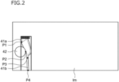
- FIG. 2 is a diagram that illustrates an example of a captured image in which positional data of the toe and the heel of the clubhead 41a, as well as the neck and an edge of the captured image at the position of the shaft 41b of the golf club 41b are detected by the specified position detecting unit 22.
- Point P1 denotes the position of the toe
- point P2 denotes the position of the heel
- point P3 denotes the position of the neck
- point P4 denotes the edge of the captured image at the position of the shaft 41b.
- the edge of the captured image at the position of the shaft 41b is an edge opposite the side of the clubhead 41a in an image that represents the shaft which is included in the captured image as illustrated in FIG. 2 . That is, the edge of the captured image at the position of the shaft 41b is an edge where a point at which the image that represents and the edge (side) of the captured image and the image of the shaft 41b intersect.
- the edge of the captured image at the position of the shaft 41b will be referred to as an "edge”.
- the specified position detecting unit 22 has a learned model obtained by machine learning of relationships between multiple captured images of clubheads 41a of golf clubs 41 and positional data of toes and heels of the clubheads 41a, as well as necks of the golf clubs 41 and the edge of the captured images at the position of shafts 41b which are included in the multiple captured images.
- the specified position detecting unit 22 inputs the captured image obtained by the captured image obtaining unit 21 into the learned model, to detect positional data of the toe, heel, neck, and edge which are included in the input captured image.
- the learned model is generated by a Convolutional Neural Network, for example.
- the present disclosure is not limited to such a configuration, and machine learning may be conducted employing other known machine learning models.
- the learned model is generated by machine learning captured images in which the positions of toes, heels, necks, and edges are annotated.
- Machine learning is conducted based on the sematic segmentation machine learning technique or the key point machine learning technique that takes a heat map into consideration.
- the learned model is that which is obtained by machine learning relationships between multiple captured images having different levels of luminosity and positional data of toes, heels, necks and edges which are included in multiple captured images. That is, it is preferable for captured images having different levels of luminosity as the multiple captured images to be employed in machine learning to obtain the learned model. Thereby, positional data of toes, heels, necks, and edges can be detected with equivalent accuracy even in the case that illumination conditions differ among captured images which are input into the learned model and the levels of luminosity differ. Note that it is more preferable for a gray scale averaging (flattening) process to be administered onto captured images by the specified position detecting unit 22 when captured images are input as targets of detection.
- the learned model is provided in the specified position detecting unit 22.
- the present disclosure is not limited to such a configuration, and a learned model which is recorded in an external server device in advance, separate from the control device 20, may be utilized.
- the control unit 23 controls the entirety of the golf impact analyzing system 1. Specifically, the control unit 23 communicates with the image capturing device 10 via the communication interface, and outputs control signals that command image capture initiating timings and image capture frame rates to the image capturing device 10. In addition, the control unit 23 communicates with the projection device 30 via the communication interface, and causes the projection device to display various types of information on the floor surface.
- control unit 23 of the present embodiment causes the projection device 30 to display various types of information on the floor surface based on the positional data of the toe and the heel of the clubhead 41a, the neck of the golf club 41, and the edge where the shaft 41b is positioned, which are detected by the specified position detecting unit 22.
- control unit 23 displays the positions of the toe, the heel, the neck, and the edge on a captured image as points, as illustrated in FIG. 2 .
- control unit 23 causes the display unit 24 to sequentially display captured images which are captured in temporal series during a swing of the golf club 41, and displays the positions of the toe, the heel, the neck, and the edge on the captured images as points.
- the movement of the positions of the toe, the heel, the neck, and the edge during the swing of the golf club 41 can be articulated, enabling confirmation of whether the swing is good or bad, as well as the suitability of the golf club 41.
- control unit 23 is capable not only of causing the projection device 30 to display the positions of the toe, the heel, the neck, and the edge as points, but also various other types of information related to the swing of the golf club 41 on the floor surface.
- control unit 23 is capable of generating and displaying a line segment that represents the clubface of the clubhead 41a, by connecting the position of the toe and the position of the heel in a captured image with a straight line.
- clubface is utilized throughout the present specification.
- the clubface is the surface of the clubhead 41a that impacts a golf ball.
- the line segment that represents the clubface is a boundary line between a crown portion and the clubface in the case of a driver, and the line segment that represents the clubface is a leading edge portion at the lowermost portion of the clubface in the case of an iron.
- control unit 23 is capable of generating a line segment that represents the clubface of the clubhead in each of the multiple captured images which are captured in temporal series during a swing of the golf club 41, and displaying a group of the line segments that represent the clubface.
- control unit 23 is capable of calculating the center positions of the line segments that represent the clubface in each of the aforementioned multiple captured images, and generating and displaying a clubhead 41a path image, by connecting the multiple center positions and performing curve approximation.
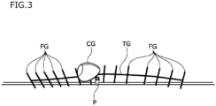
- FIG. 3 is a diagram that illustrates an example of a projected display of a group of line segments FG that represent the clubface and a clubhead 41a path image TG, which are generated by a single swing of the golf club 41.
- the projection device 30 projects and displays the group of line segments FG that represent the clubface and the club path image TG onto the floor surface as illustrated in FIG. 3 , for example.
- the element CG illustrated in FIG. 3 is a three dimensional object image that represents the clubhead.
- the three dimensional object image CG is a simulated image that represents the clubhead as a three dimensional image, different from the captured images which are captured by the image capturing device 10.
- the three dimensional object image CG that represents the clubhead is also generated by the control unit 23.
- the control unit 23 outputs the three dimensional object image CG to the projection device 30, and the projection device projects and displays the three dimensional object image CG on the floor surface.
- FIG. 3 illustrates the three dimensional object image CG at a predetermined position along the club path image TG.
- the projection device 30 may move the three dimensional object image CG along the line of the club path image TG under control of the control unit 23, to perform animated display.
- FIG. 3 illustrates an example of a projected display of a group of line segments FG that represent the clubface and a club path image TG, which are generated by a single swing of the golf club 41.
- groups of line segments and club path images generated by two or more swings may be overlapped, projected, and displayed.
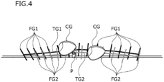
- FIG. 4 is an example of projected display of a combination of a group of line segments FG1 that represent a clubface and a club path image TG1 for the first swing and the combination of a group of line segments FG2 that represent a clubface and a club path image TG2 for the second swing.
- the combination of the group of line segments FG1 that represent a clubface and the club path image TG1 for the first swing and the combination of the group of line segments FG2 that represent a clubface and the club path image TG2 for the second swing to be projected and displayed in different colors.
- control unit 23 is capable of causing the projection device 30 to display information related to the shaft 41b of the golf club 41 on the floor surface, based on the positional data of the neck and the edge. Specifically, the control unit 23 generates and displays a line segment that represents the shaft 41b based on a line that connects the positions of the neck and the edge.
- the control unit 23 is capable of sequentially displaying the multiple captured images which are captured in temporal series during the swing of the golf club 41, and can display the line segments that represent the shaft 41b in each of the sequentially displayed captured images. Thereby, the movement of the shaft 41b during the swing of the golf club 41 can be articulated, which will be an aid to analyzing the swing and selecting a golf club.
- control unit 23 may calculate the center positions of the line segments that represent the clubface in each of the aforementioned multiple captured images, and calculate the speed of the clubhead 41a based on the distances among the center positions among frames and the frame rate.
- the control unit 23 may cause the projection device 30 to display the calculated speed of the clubhead 41a on the floor surface.
- control unit 23 causes the display unit 24 to display the positional data of the toe, the heel, the neck, and the edge, the group of line segments that represent the clubface of the clubhead 41a and the club path image, and the line segments that represent the shaft 41b.
- the display unit 24 is equipped with a display device such as a liquid crystal display.
- the input unit 25 is equipped with input devices such as a mouse and a keyboard, for example.
- the control device 20 may be constituted by a tablet terminal, and the display unit 24 and the input unit 25 may be constituted by a touch panel.
- the projection device 30 is constituted by a projector. As described above, the projection device 30 projects and displays the captured images in which the toe, the heel, the neck, and the edge are denoted by points, the group of line segments that represent the clubface, and the club path image on the floor surface.
- the projection device 30 is provided adjacent to the image capturing device 10 above the golfer who swings the golf club 41, or below the golfer in the case that a short focal length/close up lens is employed.
- the projection device 30 has a projection distance and a brightness capable of displaying the captured images, the group of line segments that represent the clubface, and the club path image on the floor surface with sufficient luminosity and clarity.
- the projection device 30 is provided so as to be capable of projecting and displaying the captured images in which the toes, the heels, the necks, and the edges are denoted by points, the group of line segments that represent the clubface, and the club path image to a predetermined projection range on the floor surface having the position P at which the golf ball 42 is placed in the vicinity of the center thereof.
- the projection device 30 may be provided on a support structure such as a stand with the image capturing device 10, or may be mounted on the ceiling.
- images of the clubhead 41a are captured from directly above.
- a stereoscopic camera may be provided as the image capturing device 10, and images of the clubhead 41a may be captured stereoscopically whereby the position of image capturing device can be provided in any other locations.
- the specified position detecting unit 22 may detect positional data of the toe, the heel, the neck, and the edge from each of the captured images which are obtained by stereoscopic image capturing, to detect the positions of the toe, the heel, the neck, and the edge in a three dimensional space. Thereby, the movement of the golf club 41 can be analyzed in greater detail.
- the control unit 23 may generate a three dimensional line segment image by connecting the positions of the toe, the heel, the neck, and the edge in the three dimensional space, and cause the display unit 24 to display the generated line segment image three dimensionally.
- each of the devices that constitute the golf impact analyzing system 1 is turned ON (S10).
- the golfer stands in the vicinity of the image capture range R as illustrated in FIG. 1 , and places the golf ball 42 at the position P within the image capture range R.
- the golfer After image capture by the image capturing device 10 is initiated, the golfer swings the golf club 41 and hits the golf ball 42 (S14).
- images in the image capture range R are captured by the image capturing device 10 at a predetermined frame rate (S16), and the captured images which are captured in temporal series are sequentially output to the control device 20.
- the image capturing device 10 ceases image capture at a point in time at which a preset amount of time elapses from initiating image capture (S18).
- the captured images output from the image capturing device 10 are input to the control device 20 and obtained by the captured image obtaining unit 21 (S20).
- the specified position detecting unit 22 inputs each of the captured images which are obtained by the captured image obtaining unit 21 into the learned model described above, and detects positional data of the toe, the heel, the neck, and the edge within each captured image (S22).
- control unit 23 causes the projection device 30 to display the multiple captured images which are captured in temporal series on the floor surface, with points at the positions of the toe, the heel, the neck, and the edge overlapped on each captured image (S24). Thereby, the states of movement of the toe, the heel, the neck, and the edge during the swing can be articulated, and information related to the swing of the golf club can be confirmed more easily.
- four points are displayed at the positions of the toe, the heel, the neck, and the edge in the embodiment described above.
- the present disclosure is not limited to such a configuration. Two points may be displayed at the positions of the toe and the heel, or three points may be displayed at the positions of the toe, the heel, and the neck, for example.
- the embodiment described above is an example in which the images of the clubhead 41a are captured from directly above.
- the angle of image capture is not limited, as long as images of at least the toe and the heel, preferably the toe, the heel, and the neck, and more preferably the toe the heel, the neck, and the edge can be captured.
- machine learning may be executed employing captured images in which images of the clubhead 41a are captured from a diagonally transverse direction such that images which are captured from this direction can be articulated to generate the learned model.
- the learned model may be that which is obtained by further machine learning relationships between multiple captured images and positional data of necks of golf clubs which are included in each of the captured images
- the specified position detecting unit may further detect positional data of a neck of a golf club
- the control unit may display information based on the positional data of the neck of the golf club.
- the learned model may be that which is obtained by further machine-learning the relationships between multiple captured images and positional data of necks of golf clubs and an edge of the multiple captured images where the shafts of golf clubs are positioned.
- the specified position detecting unit may further detect positional data of a neck of a golf club and an edge of an image where the shaft is positioned, and the control unit may display information based on the positional data of the neck of the golf club and the edge of the image where the shaft is positioned.
- control unit may generate and display a line segment that represents a clubface of a clubhead, based on positional data of a toe and a heel of the clubhead.
- control unit may generate and display a line segment that represents a shaft of a golf club, based on positional data of a neck of the golf club and an edge where the shaft is positioned.
- control unit may generate and display information regarding a club path of a clubhead, based on positional data of a toe and a heel of the clubhead.
- the learned model may be that which is obtained by machine learning the relationships between multiple captured images having different levels of luminosity and positional data of toes and heels which are included in the multiple captured images.
Landscapes
- Engineering & Computer Science (AREA)
- Theoretical Computer Science (AREA)
- Physics & Mathematics (AREA)
- General Physics & Mathematics (AREA)
- Health & Medical Sciences (AREA)
- General Health & Medical Sciences (AREA)
- Physical Education & Sports Medicine (AREA)
- Computer Vision & Pattern Recognition (AREA)
- Multimedia (AREA)
- Human Computer Interaction (AREA)
- General Engineering & Computer Science (AREA)
- Software Systems (AREA)
- Artificial Intelligence (AREA)
- Data Mining & Analysis (AREA)
- Evolutionary Computation (AREA)
- Medical Informatics (AREA)
- Computing Systems (AREA)
- Mathematical Physics (AREA)
- Signal Processing (AREA)
- Image Analysis (AREA)
- Processing Or Creating Images (AREA)
Applications Claiming Priority (2)
| Application Number | Priority Date | Filing Date | Title |
|---|---|---|---|
| JP2022077045A JP7148192B1 (ja) | 2022-05-09 | 2022-05-09 | 表示制御装置および方法並びにプログラム |
| PCT/JP2022/047052 WO2023218692A1 (ja) | 2022-05-09 | 2022-12-21 | 表示制御装置および方法並びにプログラム |
Publications (2)
| Publication Number | Publication Date |
|---|---|
| EP4523765A1 true EP4523765A1 (de) | 2025-03-19 |
| EP4523765A4 EP4523765A4 (de) | 2026-03-11 |
Family
ID=88689358
Family Applications (1)
| Application Number | Title | Priority Date | Filing Date |
|---|---|---|---|
| EP22877667.0A Pending EP4523765A4 (de) | 2022-05-09 | 2022-12-21 | Anzeigesteuerungsvorrichtung, -verfahren und -programm |
Country Status (5)
| Country | Link |
|---|---|
| US (1) | US12434098B2 (de) |
| EP (1) | EP4523765A4 (de) |
| KR (1) | KR102618193B1 (de) |
| CN (1) | CN117377517A (de) |
| AU (2) | AU2022417274B2 (de) |
Families Citing this family (1)
| Publication number | Priority date | Publication date | Assignee | Title |
|---|---|---|---|---|
| USD1075815S1 (en) * | 2021-10-28 | 2025-05-20 | Amplus Co., Ltd. | Display panel with a computer-generated icon |
Family Cites Families (15)
| Publication number | Priority date | Publication date | Assignee | Title |
|---|---|---|---|---|
| US5141230A (en) * | 1990-08-10 | 1992-08-25 | Antonious A J | Metal wood golf club head with improved weighting system |
| US7959521B2 (en) * | 2006-06-21 | 2011-06-14 | Nusbaum Mark E | Electronically controlled golf swing analyzing/training mat system with ball striking-related feedback |
| JP4241779B2 (ja) * | 2006-08-04 | 2009-03-18 | ヤマハ株式会社 | ゴルフクラブヘッド |
| WO2010083449A2 (en) * | 2009-01-19 | 2010-07-22 | Full Swing Golf, Inc. | Methods and systems for sports simulation |
| JP6069925B2 (ja) * | 2011-08-01 | 2017-02-01 | ヤマハ株式会社 | ゴルフクラブ計測システム及びゴルフクラブ |
| JP6124549B2 (ja) * | 2012-10-17 | 2017-05-10 | ダンロップスポーツ株式会社 | ゴルフクラブのスイング分析方法、スイング分析システム、及びスイング分析プログラム |
| JP6582641B2 (ja) * | 2015-07-07 | 2019-10-02 | 株式会社プロギア | ゴルフクラブのスウィングの表示方法 |
| JP2018061729A (ja) | 2016-10-14 | 2018-04-19 | 株式会社フローベル | 画像処理システムおよびその制御方法 |
| US12172066B2 (en) * | 2017-01-17 | 2024-12-24 | Arccos Golf Llc | Autonomous tracking and personalized golf recommendation and analysis environment |
| US10953303B2 (en) * | 2017-12-22 | 2021-03-23 | Trackman A/S | System and method for determining impact characteristics of sports ball striking element |
| JP7161609B2 (ja) * | 2020-01-16 | 2022-10-26 | クリーツ インク | ゴルフクラブと関連する物理量を測定するための方法、システムおよび非一過性のコンピュータ読み取り可能記録媒体 |
| KR102807799B1 (ko) * | 2020-01-21 | 2025-05-15 | 트랙맨 에이/에스 | 스포츠 볼을 추적하는 시스템 및 방법 |
| WO2021158688A1 (en) * | 2020-02-05 | 2021-08-12 | Rayem Inc. | A portable apparatus, method, and system of golf club swing motion tracking and analysis |
| GB2599627A (en) * | 2020-09-18 | 2022-04-13 | Sony Group Corp | Method, apparatus and computer program product for generating a path of an object through a virtual environment |
| JP6904624B1 (ja) * | 2021-01-21 | 2021-07-21 | 有限会社Amplus | クラブヘッド計測用マークおよび画像処理装置 |
-
2022
- 2022-12-21 CN CN202280006841.6A patent/CN117377517A/zh active Pending
- 2022-12-21 KR KR1020237027857A patent/KR102618193B1/ko active Active
- 2022-12-21 AU AU2022417274A patent/AU2022417274B2/en active Active
- 2022-12-21 EP EP22877667.0A patent/EP4523765A4/de active Pending
-
2023
- 2023-04-18 US US18/136,074 patent/US12434098B2/en active Active
-
2024
- 2024-05-07 AU AU2024203001A patent/AU2024203001A1/en active Pending
Also Published As
| Publication number | Publication date |
|---|---|
| KR102618193B1 (ko) | 2023-12-27 |
| CA3204843A1 (en) | 2023-11-09 |
| AU2022417274A1 (en) | 2023-11-23 |
| KR20230158468A (ko) | 2023-11-20 |
| CN117377517A (zh) | 2024-01-09 |
| AU2022417274B2 (en) | 2024-02-08 |
| US12434098B2 (en) | 2025-10-07 |
| US20240115904A1 (en) | 2024-04-11 |
| AU2024203001A1 (en) | 2024-05-30 |
| EP4523765A4 (de) | 2026-03-11 |
Similar Documents
| Publication | Publication Date | Title |
|---|---|---|
| JP5858433B2 (ja) | 注視点検出方法及び注視点検出装置 | |
| JP7148192B1 (ja) | 表示制御装置および方法並びにプログラム | |
| CN111488775B (zh) | 注视度判断装置及方法 | |
| US11583746B2 (en) | Measurement and reconstruction of the golf launching scene in 3D | |
| JP6904624B1 (ja) | クラブヘッド計測用マークおよび画像処理装置 | |
| US20230364468A1 (en) | Deep learning method of determining golf swing and golf ball parameters from radar signal and image data | |
| EP4523765A1 (de) | Anzeigesteuerungsvorrichtung, -verfahren und -programm | |
| JP6986766B2 (ja) | 画像処理装置およびプログラム | |
| CA3204843C (en) | Method, apparatus, and program for controlling display | |
| JP7554534B2 (ja) | レーダ信号及び画像データの両方からゴルフクラブのパラメータを決定する深層学習方法 | |
| KR20170048491A (ko) | 이동체의 거동 계측 방법 및 거동 계측 장치 | |
| WO2024147210A1 (ja) | 表示制御装置および方法並びにプログラム | |
| US20250086927A1 (en) | Display control apparatus, display control method, and display control program | |
| HK40097026A (zh) | 显示控制装置、方法及程序 | |
| JP7269617B2 (ja) | 顔画像処理装置、画像観察システム、及び瞳孔検出システム | |
| EP4715786A1 (de) | Schwunganalysevorrichtung und schwunganalyseprogramm | |
| JP6710961B2 (ja) | ゴルフスイングの解析方法 | |
| CN114681886B (zh) | 高尔夫挥杆解析系统、高尔夫挥杆解析方法及信息存储媒体 | |
| US20260021366A1 (en) | Sport simulation device | |
| HK40109695A (zh) | 显示控制装置、方法及程序 | |
| JP2006204359A (ja) | ゴルフボール試打機 | |
| JP2013031531A (ja) | ゴルフスイングの計測システム及び計測方法 |
Legal Events
| Date | Code | Title | Description |
|---|---|---|---|
| STAA | Information on the status of an ep patent application or granted ep patent |
Free format text: STATUS: UNKNOWN |
|
| STAA | Information on the status of an ep patent application or granted ep patent |
Free format text: STATUS: THE INTERNATIONAL PUBLICATION HAS BEEN MADE |
|
| PUAI | Public reference made under article 153(3) epc to a published international application that has entered the european phase |
Free format text: ORIGINAL CODE: 0009012 |
|
| STAA | Information on the status of an ep patent application or granted ep patent |
Free format text: STATUS: REQUEST FOR EXAMINATION WAS MADE |
|
| 17P | Request for examination filed |
Effective date: 20230412 |
|
| AK | Designated contracting states |
Kind code of ref document: A1 Designated state(s): AL AT BE BG CH CY CZ DE DK EE ES FI FR GB GR HR HU IE IS IT LI LT LU LV MC ME MK MT NL NO PL PT RO RS SE SI SK SM TR |
|
| DAV | Request for validation of the european patent (deleted) | ||
| DAX | Request for extension of the european patent (deleted) | ||
| REG | Reference to a national code |
Ref country code: DE Ref legal event code: R079 Free format text: PREVIOUS MAIN CLASS: A63B0069360000 Ipc: G06T0007246000 |
|
| A4 | Supplementary search report drawn up and despatched |
Effective date: 20260211 |
|
| RIC1 | Information provided on ipc code assigned before grant |
Ipc: G06T 7/246 20170101AFI20260205BHEP Ipc: A63B 69/36 20060101ALI20260205BHEP Ipc: H04N 7/18 20060101ALI20260205BHEP Ipc: A63B 69/00 20060101ALI20260205BHEP Ipc: A63B 24/00 20060101ALI20260205BHEP |