EP4521902A1 - Oled-vorrichtung zur erzeugung von licht und aktives signalisierungssystem eines arbeiters mit dieser vorrichtung - Google Patents
Oled-vorrichtung zur erzeugung von licht und aktives signalisierungssystem eines arbeiters mit dieser vorrichtung Download PDFInfo
- Publication number
- EP4521902A1 EP4521902A1 EP24198597.7A EP24198597A EP4521902A1 EP 4521902 A1 EP4521902 A1 EP 4521902A1 EP 24198597 A EP24198597 A EP 24198597A EP 4521902 A1 EP4521902 A1 EP 4521902A1
- Authority
- EP
- European Patent Office
- Prior art keywords
- transparent
- oled
- light
- fabric
- layer
- Prior art date
- Legal status (The legal status is an assumption and is not a legal conclusion. Google has not performed a legal analysis and makes no representation as to the accuracy of the status listed.)
- Pending
Links
Images


Classifications
-
- H—ELECTRICITY
- H10—SEMICONDUCTOR DEVICES; ELECTRIC SOLID-STATE DEVICES NOT OTHERWISE PROVIDED FOR
- H10K—ORGANIC ELECTRIC SOLID-STATE DEVICES
- H10K59/00—Integrated devices, or assemblies of multiple devices, comprising at least one organic light-emitting element covered by group H10K50/00
- H10K59/30—Devices specially adapted for multicolour light emission
- H10K59/38—Devices specially adapted for multicolour light emission comprising colour filters or colour changing media [CCM]
-
- F—MECHANICAL ENGINEERING; LIGHTING; HEATING; WEAPONS; BLASTING
- F21—LIGHTING
- F21V—FUNCTIONAL FEATURES OR DETAILS OF LIGHTING DEVICES OR SYSTEMS THEREOF; STRUCTURAL COMBINATIONS OF LIGHTING DEVICES WITH OTHER ARTICLES, NOT OTHERWISE PROVIDED FOR
- F21V33/00—Structural combinations of lighting devices with other articles, not otherwise provided for
- F21V33/0004—Personal or domestic articles
- F21V33/0008—Clothing or clothing accessories, e.g. scarfs, gloves or belts
-
- H—ELECTRICITY
- H10—SEMICONDUCTOR DEVICES; ELECTRIC SOLID-STATE DEVICES NOT OTHERWISE PROVIDED FOR
- H10K—ORGANIC ELECTRIC SOLID-STATE DEVICES
- H10K2102/00—Constructional details relating to the organic devices covered by this subclass
- H10K2102/301—Details of OLEDs
- H10K2102/302—Details of OLEDs of OLED structures
- H10K2102/3023—Direction of light emission
- H10K2102/3031—Two-side emission, e.g. transparent OLEDs [TOLED]
Definitions
- the present invention in general, relates to devices based on OLED (organic light-emitting diode) technology.
- a first aspect of the present invention relates to an OLED device capable of generating light of a desired colour (monochromatic OLED), or preferably white light.
- a second aspect of the present invention is an active signalling system for an operator who uses such an OLED device on fabric.
- a third aspect of the present invention also relates to a system for signalling the presence of a person, even at a distance. More specifically, an OLED device is constructed directly on items of clothing, including workwear.
- Technical clothing is a key element for numerous categories of workers (for example, workers in the construction, road, mining, etc. industries).
- Technical fabrics, for these categories of workers must have some additional properties to those of traditional fabrics, so as to make the garments suitable for use in the workplace; examples include high mechanical strength (e.g. against cuts and perforations) and fire resistance.
- prevention can be implemented through the use of devices capable of enhancing an operator's visibility in the workplace.
- Such prevention systems can be passive or active and support the worker by making him/her visible even in poorly lit environments.
- reflector components are among the most common, but have the disadvantage of improving the visibility of a user only when illuminated by other sources.
- Fabrics containing reflector components provide a passive prevention of accidents, not completely nor under every circumstance solving the problem of signalling the presence of a worker.
- a reflective fabric is used to increase the light from a light source (e.g. light-emitting diodes, LEDs or OLEDs).
- a light source e.g. light-emitting diodes, LEDs or OLEDs.
- OLEDs owed to their demonstrated greater flexibility compared with LEDs, is preferable, especially in a field such as the manufacture of professional garments, where greater flexibility equates to easier movement for a worker, which is also important in the prevention of accidents.
- a top emitting architecture In general, in order to be able to integrate an OLED device on a non-transparent substrate (such as a technical fabric), a top emitting architecture must be used, as shown in Figure 1 .
- Such OLED architectures provide for the application of a reflective electrode onto a smooth, rigid or flexible substrate. Organic layers and a transparent upper electrode are then deposited on the reflective electrode, allowing the light generated inside the device to escape.
- This light is in general monochromatic when the emissive layer is formed by a single material.
- red, green and blue light emitting materials are used, assembled in different configurations, as shown in Figure 1 .
- the monochromatic light sources can be further combined with one another to produce additional colours (e.g. secondary colours).
- WO 2005/005 571 describes an electroluminescent element comprising an organic or inorganic material that emits blue light and at least one fluorescent material, which absorbs that blue light, in turn re-emitting a fluorescence in the region of visible light at lower energy.
- the organic or inorganic material includes a diketopyrrolopyrrole.
- the fluorescent material in WO 2005/005 571 , is in the form of powder.
- US 2016/0 043 288 describes a system formed by a LED module, emitting blue light, and a resin to which a fluorescent powder has been added, capable of converting part of the blue light emitted by the LED, generating white light.
- Systems such as the one just described are based on LED technology, and therefore on rigid and bulky systems. These characteristics, with a view to integration on technical fabrics, would have a negative impact on the comfort of the item of clothing.
- white light is preferable as regards active signalling, since in poorly lit environments (such as roadways under poorly lit conditions), or in environments with large amounts of dust (building sites, mines), or even in environments with large amounts of smoke, white light is easily detectable by the human eye. Furthermore, it does not alter the colour perception of objects and people in the immediate vicinity.
- the OLED device generating light of a determined wavelength (colour) is characterised in that a device based on monochromatic emission OLED technology is combined with luminescent fabric.
- the latter must be capable of absorbing part of the light emitted by the OLED and re-emitting it with a different colour (at a greater wavelength).
- a second possibility provides for the use of an electroluminescent system, formed by:
- an OLED device capable of generating (preferably white) light
- the application of which can vary from the active signalling of a user to, for example, applications related to the field of shipments
- an OLED device according to the present invention can be installed on a package, in order to highlight any fragility or possible biological/chemical risk of the contents, to alert shipping personnel to exercise caution) or for advertising (for example, supplying lightweight and highly flexible installations for indoor and/or outdoor use).
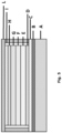
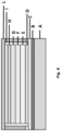
- FIG. 2 An OLED device according to the present invention is shown schematically in Figure 2 .
- the device/system according to the present invention manipulates light (preferably blue light) provided by an OLED component, so as to obtain light of a desired colour (preferably white) in an extremely simple manner.
- the manipulation of the light produced by an OLED component takes place through a single manipulation means, i.e. a luminescent fabric; hence, also being of reduced size and greater constructional simplicity compared with the prior art.
- the device is essentially formed by an OLED component, which is formed by two semi-transparent or transparent electrodes, and an organic multilayer (which includes an emissive layer) and cooperates, through a planarising layer or alternatively through an adhesive layer (both transparent), with a luminescent fabric, which is to be considered a constituent part of the device/system according to the present invention.
- an OLED component which is formed by two semi-transparent or transparent electrodes, and an organic multilayer (which includes an emissive layer) and cooperates, through a planarising layer or alternatively through an adhesive layer (both transparent), with a luminescent fabric, which is to be considered a constituent part of the device/system according to the present invention.
- Cooperation between the OLED component and the luminescent fabric is made functional through the planarising or adhesive layer, and is maintained through integration or installation.
- the OLED component of the present invention is protected from water vapour, oxygen and dust by anti-permeant layers, which will be discussed in detail later.
- the light emitted by the emitting layer has a wavelength in the visible region, preferably between 425 nm and 525 nm, i.e. in a range which varies from blue through to cyan/green.
- the luminescent fabric must be capable of absorbing light at these wavelengths (and re-emitting it in a different colour), such that the device/system according to the present invention is capable of generating secondary or white overlapped light.
- the emitting layer of the OLED component can be formed by polymers or small electroluminescent molecules. It is understood that the two electrodes in the component play the role of cathode and anode during operation. Without limitations, the two electrodes can be:
- Particularly preferred embodiments of the OLED component contain a combination of two different electrodes, of the types listed above.
- ITO films as lower electrode and Ag/WOs multilayer as upper electrode.
- the requirement to be met for the use of a material as electrode in the OLED system of the present invention is semi-transparency or transparency (a transmittance higher than 30%, more preferably a transmittance higher than 60%).
- the planarising layer illustrated in Figure 2 can be defined as a layer that minimises the surface roughness of the underlying fabric.
- the planarising layer corrects the surface morphology of a fabric, which as is known has gaps between warp and weft, exposed fibres, local inhomogeneities, etc.
- the planarising layer is hence applied to a rough and inhomogeneous surface (that of the fabrics), with the aim of planarising the surface (reducing the roughness to a few nm) on which the layers forming an OLED device will then be deposited.
- the use of a planarising layer is necessary for the correct operation of the system according to the invention, since OLED technology is intrinsically incompatible with applications on rough or irregular surfaces, such as those of fabrics, including technical fabrics.
- the surface with which an OLED component cooperates is coarse or rough, being an OLED component formed by extremely thin stacked layers (such as electrodes, emitting layer etc.), the surface roughness is transferred to each layer, adversely affecting the performance of the component or even compromising operation.
- cooperation between the OLED component and the luminescent fabric is established by manufacturing the OLED component directly on said luminescent fabric, including a planarising layer, deposited by techniques compatible with the processing of fabrics, for example dip coating, inkjet printing, lamination, roller transfer, doctor blading, spatula coating, etc.
- cooperation between the OLED component and the luminescent fabric is established by installing the OLED component on the fabric. Installation can be by bonding with specific transparent adhesive films deposited by lamination, printing or other compatible techniques; or by applying buttons or other means available to the person skilled in the art.
- the surface with which the component cooperates, as anticipated, is indeed a luminescent fabric, preferably a luminescent technical fabric, made either of natural fibres or of synthetic fibres or of a blend of natural and synthetic fibres.
- the fabric is a blend of cotton and polyester.
- the fabric is a 50/50 blend of cotton and polyester.
- one or more transparent impermeable layers must be added to protect the component from external agents, mainly from oxygen and moisture, in order to prevent the component from being damaged, reducing its performance or interrupting its operation.
- anti-permeant layers are commercially available from Vitex (Barix product) and 3M (FTB3-50 and similar).
- the one or more impermeable layers are preferably closed by heat or by resins, sealing the edges thereof and providing a pouch-type coating, conforming to the component, or even sealed by the application of specific resins distributed over the entire surface of the device, on which the impermeable layer is then laminated.
- An additional method for encapsulating the OLED device provides for the deposition of an anti-permeant multilayer directly on the surface of the device, by means of thin film encapsulation (TFE) techniques.
- TFE thin film encapsulation
- the OLED device can then interact with the luminescent fabric to modulate the colour of the light emitted overall.
- the inventors have discovered that, in order to generate white or secondary light, it is necessary to place an electroluminescent device in contact with a luminescent fabric.
- an OLED system of the type described previously is particularly preferred, in which the light emitted by the single emitting layer has a wavelength within the visible range (between 380 nm and 780 nm), preferably between 425 nm and 525 nm, in which the luminescent fabric down-converts part of the light emitted by the single layer into a light with a longer wavelength.
- the luminescent fabric is capable of converting (changing the colour) part of the light emitted by the single emissive layer; the light emitted by the single emissive layer together with the converted light, overlapping on one another, generate a combined light, preferably white.
- the light generated i.e. preferably blue light
- the two electrodes and the planarising layer are transparent or semi-transparent, the light begins to spread to both the side on which it is cooperating with the fabric and to the outside.
- the light scattered towards the luminescent fabric is absorbed and undergoes a conversion process (down-conversion) - a process in which high energy light (shorter wavelength) is absorbed by a luminescent material and then re-emitted at lower energy light (longer wavelength).
- the OLED source in order to obtain white light, the OLED source must emit blue light, and must be partially absorbed by a luminescent fabric that re-emits it in orange/red colour, such that the overlapping between blue and orange/red gives rise to an overall white light.
- Examples of emission spectra of active signalling systems are illustrated in Figure 4 for the case of an OLED component of the type described above installed on a luminescent and non-luminescent fabric.
- the non-luminescent fabric does not allow light conversion and a simple emission of light takes place, peaked in the blue region (470 nm), whereas in the case of the luminescent fabric (in the red region), the emitted light comprises a good part of the wavelengths in the visible range (450 nm to 750 nm), with a peak in the blue region (470 nm) and one in the red region (610 nm), therefore resulting in white.
- Luminex models which are either orange or red or orange/red in colour.
- the active signalling system according to the invention also functions on luminescent fabrics on which finishes (of the kind that make the fabric impermeable) have been applied, as in the case of the Luminex C50 model, also of the Applicant.
- the active signalling system component can be obtained by prefabricating the OLED component and, once sealed with impermeable layers, establishing co-operation with a fluorescent fabric by means that are known per se, such as by adhesives, glues, or by using snap fasteners.
- the OLED component should be placed between two impermeable layers, which must then be thermally bonded or bonded together, so as to protect the component from environmental moisture.
- the OLED or active signalling system may also be constructed by directly applying, in the following order, to a luminescent fabric: a planarising layer, an impermeable layer, an OLED component of the type described above and a second impermeable layer. It is understood that in the abovementioned construction methods, the sealing of the OLED component is carried out by hot-melting means or by bonding of impermeable layers.
- the impermeable layers can be sealed along the perimeter of the component, in that case ensuring a pouch-type coating, or sealed by the application of specific resins distributed over the entire surface of the device, on which the impermeable layer is subsequently laminated, or by the deposition of an anti-permeant multilayer directly on the surface of the device, using thin film encapsulation (TFE) techniques.
- TFE thin film encapsulation
- the OLED device and the active signalling system of the present invention do not require reflecting means (such as refracting means or mirrors) to be able to enhance the light emitted and, moreover, it is simple from a construction perspective and exhibits high mechanical flexibility.
- the impermeable layers protect the system from malfunctions due to moisture, dust, oxygen and other atmospheric agents, ensuring longevity of the system and enabling it to even be used outdoors.
- the active signalling system can be installed on technical clothing, such as workers' vests, shirts, overalls, trousers, jackets and shoes.
- the active signalling system can be paired with a portable battery: simply connect the system to a DC supply, with an operating range compatible with the OLED system.
- Programming can be added to the OLED-based active signalling device, in a manner that is known per se, such that it follows a particular on/off sequence, for example to signal an emergency or danger condition of the worker.
- Pulsed light especially irregular pulse light, as is known, is easily perceived by the human eye.
- the active signalling component it is also possible to apply the active signalling component to a sportsperson running in dimly lit environments.
Landscapes
- Engineering & Computer Science (AREA)
- General Engineering & Computer Science (AREA)
- Electroluminescent Light Sources (AREA)
Applications Claiming Priority (1)
| Application Number | Priority Date | Filing Date | Title |
|---|---|---|---|
| IT202300018360 | 2023-09-07 |
Publications (1)
| Publication Number | Publication Date |
|---|---|
| EP4521902A1 true EP4521902A1 (de) | 2025-03-12 |
Family
ID=88689525
Family Applications (1)
| Application Number | Title | Priority Date | Filing Date |
|---|---|---|---|
| EP24198597.7A Pending EP4521902A1 (de) | 2023-09-07 | 2024-09-05 | Oled-vorrichtung zur erzeugung von licht und aktives signalisierungssystem eines arbeiters mit dieser vorrichtung |
Country Status (1)
| Country | Link |
|---|---|
| EP (1) | EP4521902A1 (de) |
Citations (6)
| Publication number | Priority date | Publication date | Assignee | Title |
|---|---|---|---|---|
| WO2005005571A1 (en) | 2003-07-09 | 2005-01-20 | Ciba Specialty Chemicals Holding Inc. | Colour changing media for light emitting display devices |
| US20120062110A1 (en) * | 2009-05-20 | 2012-03-15 | Hochschule Niederrhein | Electroluminescent textile and method for the production thereof |
| KR20140069443A (ko) * | 2012-11-29 | 2014-06-10 | 한국과학기술원 | 유기발광소자를 포함하는 전계발광 직물, 및 유기발광소자를 포함하는 전계발광 직물의 제조 방법 |
| WO2015148769A1 (en) | 2014-03-27 | 2015-10-01 | Seke Llc | Layered reflective strip, article, and/or garment, and methods for integrating electronic and/or electrical components for improving awareness, safety, and/or visibiity |
| US20160043288A1 (en) | 2014-08-11 | 2016-02-11 | Bright Led Electronics Corp. | Light-emitting diode module capable of reducing blue-light energy |
| US20200027931A1 (en) * | 2017-12-12 | 2020-01-23 | Universal Display Corporation | Hybrid Wearable Organic Light Emitting Diode (OLED) Illumination Devices |
-
2024
- 2024-09-05 EP EP24198597.7A patent/EP4521902A1/de active Pending
Patent Citations (6)
| Publication number | Priority date | Publication date | Assignee | Title |
|---|---|---|---|---|
| WO2005005571A1 (en) | 2003-07-09 | 2005-01-20 | Ciba Specialty Chemicals Holding Inc. | Colour changing media for light emitting display devices |
| US20120062110A1 (en) * | 2009-05-20 | 2012-03-15 | Hochschule Niederrhein | Electroluminescent textile and method for the production thereof |
| KR20140069443A (ko) * | 2012-11-29 | 2014-06-10 | 한국과학기술원 | 유기발광소자를 포함하는 전계발광 직물, 및 유기발광소자를 포함하는 전계발광 직물의 제조 방법 |
| WO2015148769A1 (en) | 2014-03-27 | 2015-10-01 | Seke Llc | Layered reflective strip, article, and/or garment, and methods for integrating electronic and/or electrical components for improving awareness, safety, and/or visibiity |
| US20160043288A1 (en) | 2014-08-11 | 2016-02-11 | Bright Led Electronics Corp. | Light-emitting diode module capable of reducing blue-light energy |
| US20200027931A1 (en) * | 2017-12-12 | 2020-01-23 | Universal Display Corporation | Hybrid Wearable Organic Light Emitting Diode (OLED) Illumination Devices |
Similar Documents
| Publication | Publication Date | Title |
|---|---|---|
| JP5335909B2 (ja) | エレクトロルミネセント・ディスプレイ装置、照明装置または表示装置、並びに、その製造プロセス | |
| KR101512274B1 (ko) | 유기 발광 소자 및 이의 제조방법 | |
| JP5193208B2 (ja) | 発光デバイス | |
| TW594619B (en) | Organic electroluminescent display panel | |
| KR20100126428A (ko) | 양면형 유기 발광 다이오드(oled) | |
| US7358661B2 (en) | Organic electroluminescent device and display | |
| JP5198566B2 (ja) | オプトエレクトロニクスデバイス | |
| TW201600327A (zh) | 用於封裝的積層體、有機發光裝置及其製造方法、包括該有機發光裝置的顯示裝置以及照明裝置 | |
| JP2021516413A (ja) | 封止構造、表示デバイス及び表示装置 | |
| KR20120043027A (ko) | 게터 물질을 갖는 밀폐형 패키지 | |
| US20120032211A1 (en) | Optoelectronic Component | |
| US20070210703A1 (en) | Electroluminescent device and method for producing it | |
| KR101866296B1 (ko) | 유기 발광 소자 및 이의 제조방법 | |
| EP4521902A1 (de) | Oled-vorrichtung zur erzeugung von licht und aktives signalisierungssystem eines arbeiters mit dieser vorrichtung | |
| KR101676681B1 (ko) | 광전자 컴포넌트, 광전자 컴포넌트를 생산하기 위한 방법, 공간을 분리하기 위한 디바이스, 그리고 가구 | |
| US10100985B2 (en) | Organic light-emitting device for lighting | |
| JPH09204982A (ja) | 有機薄膜el素子 | |
| TWI338533B (en) | White organic electroluminescent elements and display using the same | |
| US10535720B2 (en) | Organic light emitting diode lighting device | |
| KR20130008100A (ko) | 유기 발광 조명 장치 | |
| JP2016207740A (ja) | 二面発光装置 | |
| US20100295074A1 (en) | Light-Emitting Component Having a Wavelength Converter and Production Method | |
| US20130113366A1 (en) | Color control of solid state light sources | |
| KR101947381B1 (ko) | 플렉서블 기판의 제조방법 및 이를 포함하는 유기 발광 소자의 제조방법 | |
| KR20170106303A (ko) | 발광 소자, 발광 소자의 제작 방법 및 발광 소자의 작동 방법 |
Legal Events
| Date | Code | Title | Description |
|---|---|---|---|
| PUAI | Public reference made under article 153(3) epc to a published international application that has entered the european phase |
Free format text: ORIGINAL CODE: 0009012 |
|
| STAA | Information on the status of an ep patent application or granted ep patent |
Free format text: STATUS: THE APPLICATION HAS BEEN PUBLISHED |
|
| AK | Designated contracting states |
Kind code of ref document: A1 Designated state(s): AL AT BE BG CH CY CZ DE DK EE ES FI FR GB GR HR HU IE IS IT LI LT LU LV MC ME MK MT NL NO PL PT RO RS SE SI SK SM TR |
|
| STAA | Information on the status of an ep patent application or granted ep patent |
Free format text: STATUS: REQUEST FOR EXAMINATION WAS MADE |
|
| 17P | Request for examination filed |
Effective date: 20250911 |