EP4521079A1 - Bordseitiges flugzeuggewichts- und -gleichgewichtsdetektionssystem - Google Patents
Bordseitiges flugzeuggewichts- und -gleichgewichtsdetektionssystem Download PDFInfo
- Publication number
- EP4521079A1 EP4521079A1 EP24198639.7A EP24198639A EP4521079A1 EP 4521079 A1 EP4521079 A1 EP 4521079A1 EP 24198639 A EP24198639 A EP 24198639A EP 4521079 A1 EP4521079 A1 EP 4521079A1
- Authority
- EP
- European Patent Office
- Prior art keywords
- aircraft
- shock strut
- landing gear
- load
- shock
- Prior art date
- Legal status (The legal status is an assumption and is not a legal conclusion. Google has not performed a legal analysis and makes no representation as to the accuracy of the status listed.)
- Pending
Links
Images


Classifications
-
- G—PHYSICS
- G01—MEASURING; TESTING
- G01M—TESTING STATIC OR DYNAMIC BALANCE OF MACHINES OR STRUCTURES; TESTING OF STRUCTURES OR APPARATUS, NOT OTHERWISE PROVIDED FOR
- G01M17/00—Testing of vehicles
- G01M17/007—Wheeled or endless-tracked vehicles
- G01M17/04—Suspension or damping
-
- B—PERFORMING OPERATIONS; TRANSPORTING
- B64—AIRCRAFT; AVIATION; COSMONAUTICS
- B64D—EQUIPMENT FOR FITTING IN OR TO AIRCRAFT; FLIGHT SUITS; PARACHUTES; ARRANGEMENT OR MOUNTING OF POWER PLANTS OR PROPULSION TRANSMISSIONS IN AIRCRAFT
- B64D47/00—Equipment not otherwise provided for
- B64D47/02—Arrangements or adaptations of signal or lighting devices
-
- B—PERFORMING OPERATIONS; TRANSPORTING
- B64—AIRCRAFT; AVIATION; COSMONAUTICS
- B64C—AEROPLANES; HELICOPTERS
- B64C25/00—Alighting gear
- B64C25/32—Alighting gear characterised by elements which contact the ground or similar surface
- B64C25/58—Arrangements or adaptations of shock-absorbers or springs
-
- B—PERFORMING OPERATIONS; TRANSPORTING
- B64—AIRCRAFT; AVIATION; COSMONAUTICS
- B64D—EQUIPMENT FOR FITTING IN OR TO AIRCRAFT; FLIGHT SUITS; PARACHUTES; ARRANGEMENT OR MOUNTING OF POWER PLANTS OR PROPULSION TRANSMISSIONS IN AIRCRAFT
- B64D43/00—Arrangements or adaptations of instruments
-
- B—PERFORMING OPERATIONS; TRANSPORTING
- B64—AIRCRAFT; AVIATION; COSMONAUTICS
- B64D—EQUIPMENT FOR FITTING IN OR TO AIRCRAFT; FLIGHT SUITS; PARACHUTES; ARRANGEMENT OR MOUNTING OF POWER PLANTS OR PROPULSION TRANSMISSIONS IN AIRCRAFT
- B64D45/00—Aircraft indicators or protectors not otherwise provided for
-
- G—PHYSICS
- G01—MEASURING; TESTING
- G01G—WEIGHING
- G01G19/00—Weighing apparatus or methods adapted for special purposes not provided for in the preceding groups
- G01G19/02—Weighing apparatus or methods adapted for special purposes not provided for in the preceding groups for weighing wheeled or rolling bodies, e.g. vehicles
- G01G19/07—Weighing apparatus or methods adapted for special purposes not provided for in the preceding groups for weighing wheeled or rolling bodies, e.g. vehicles for weighing aircraft
-
- G—PHYSICS
- G01—MEASURING; TESTING
- G01M—TESTING STATIC OR DYNAMIC BALANCE OF MACHINES OR STRUCTURES; TESTING OF STRUCTURES OR APPARATUS, NOT OTHERWISE PROVIDED FOR
- G01M1/00—Testing static or dynamic balance of machines or structures
- G01M1/12—Static balancing; Determining position of centre of gravity
- G01M1/122—Determining position of centre of gravity
- G01M1/125—Determining position of centre of gravity of aircraft
Definitions
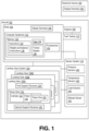
- the present disclosure is generally related to an onboard aircraft weight and balance detection system for an aircraft.
- a weight of an aircraft and balance of the aircraft are factors affecting aircraft safety.
- An aircraft that weighs more than an acceptable gross weight, that is unbalanced e.g., an aircraft with a center of gravity (CG) outside of allowable limits
- CG center of gravity
- Weight and balance of the aircraft influence many factors associated with a flight of the aircraft including fuel needed for the flight, runway lengths needed for takeoff and landing, horizontal stabilizer settings, handling characteristics, etc.
- Weight scales may be used to determine the weight and the balance of the aircraft. Having weight scales at each location where aircraft are loaded and unloaded would be impractical due to expense, aircraft configuration differences among models of aircraft, maintenance needed for the weight scales, and other factors.
- an aircraft e.g., a passenger aircraft or a cargo aircraft that includes a landing gear system with pneumatic shock struts
- an aircraft e.g., a passenger aircraft or a cargo aircraft that includes a landing gear system with pneumatic shock struts
- a system that enables a computer system of the aircraft to determine the weight and balance of the aircraft based on sensor data obtained from sensors coupled to the aircraft.
- an aircraft in a particular implementation, includes a plurality of landing gear. Each landing gear of the plurality of landing gear includes a shock strut. The aircraft includes a plurality of sensors associated with each landing gear. The plurality of sensors includes a pressure sensor configured to generate pressure data indicative of a gas pressure in the shock strut, and a temperature sensor configured to generate temperature data indicative of gas temperature in the shock strut. The aircraft also includes a computer system.
- the computer system is configured to determine, for each shock strut of the plurality of landing gear for a first time corresponding to an end of a first change in the gas pressure due to movement of a piston of the shock strut during loading or unloading of the aircraft, a friction value associated with the shock strut based on the gas pressure at the first time indicated by the pressure data and a gas temperature at the first time indicated by the temperature data.
- the computer system is configured to compute, for a particular time before the loading or the unloading of the aircraft causes a second change in gas pressure of one or more of the shock struts as indicated by the load sensor data for the shock struts, a weight of the aircraft based on the gas pressures of the shock struts at the first times and the friction values associated with the shock struts at the first times.
- the computer system is also configured to provide, to one or more display devices, first output that indicates the weight of the aircraft.
- a method of determining weight of an aircraft having a plurality of landing gear includes obtaining, at a computer system, pressure data and temperature data for gas in respective ones of shock struts of the plurality of landing gear during loading or unloading of the aircraft.
- the method includes determining, at the computer system for each shock strut of the plurality of landing gear for a first time corresponding to an end of a first change in gas pressure due to movement of a piston of the shock strut during the loading or the unloading of the aircraft, a friction value associated with the shock strut based on a gas pressure at the first time indicated by the pressure data and a gas temperature at the first time indicated by the temperature data.
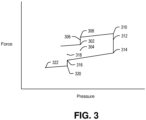
- the static friction force acts to resist movement of the piston toward the cylinder end.
- the static friction force increases as the load increases up to a compression breakout friction force, and the gas pressure of the shock strut does not change. If the load is further increased when the static friction force is at the compression breakout friction force, the shock strut becomes a dynamic system and the friction force becomes a dynamic friction force.
- the dynamic friction force is directly proportional to the load (i.e., a magnitude of the dynamic friction force equals a coefficient of kinetic friction, which is less than the coefficient of static friction, multiplied by the load) and acts in a direction opposite to a direction of movement of the piston.
- the load sensors can be used to determine load delta values that are reliable and accurate for a time period between a first time and a second time that indicate a load change.
- a determination may be made regarding the accuracy of the load delta values generated by the load sensors of the aircraft by determining the weight of the aircraft at a first time, adding a known weight at a second time, and determining a second weight of the aircraft after the second time and before the weight of the aircraft is additionally changed. If the value of second weight is not the first weight plus the known weight within acceptable error limits, one or more of the load sensors are faulty and additional procedures can be initiated to identify and replace faulty load sensors.
- the weight and balance instructions 136 also use appropriate trigonometric functions to compensate for any pitch of the aircraft 100 relative to the horizontal side-to-side axis based on the value of the nose down tilt angle of the aircraft 100 relative to horizontal when the aircraft 100 is on level ground stored in the data 134 and based on pitch attitude data from the attitude sensor 146.
- the computer system 112 provides output of the weight and balance instructions 136 to output devices.
- the output devices include one or more display devices 148 of the aircraft 100, one or more external devices (e.g., a portable device associated with a load master tasked with loading or unloading the aircraft), audio devices, haptic devices, other types of output devices, or combinations thereof.
- the output can include the weight of the aircraft 100, the zero fuel weight of the aircraft 100 (i.e., weight minus fuel weight), the location of the center of gravity of the aircraft 100, warnings associated with the weight of the aircraft 100, warnings associated with the center of gravity of the aircraft 100, other information, or combinations thereof.
- FIG. 2 depicts a side view representation of a portion of the aircraft 100 on ground 202.
- the ground 202 depicted in FIG. 2 is level relative to a horizontal 204. In other situations, the ground 202 may be at a non-zero angle relative to the horizontal 204.
- the aircraft 100 includes a fore-aft axis 206.
- a parameter of the aircraft 100 is the tilt angle ⁇ between the fore-aft axis 206 and the horizontal 204 when the aircraft 100 is on level ground, which is stored in the data 134 of the memory 130 of the computer system 112.
- the nose landing gear 106A is at a first angle, ⁇ nlg, relative to a first axis 208 perpendicular to the fore-aft axis 206 of the aircraft 100.
- Each of the main landing gear 106B are at a second angle, ⁇ mlg, relative to a second axis 210 perpendicular to the fore-aft axis 206 of the aircraft 100.
- Parameters of the aircraft 100 include values of ⁇ nlg and ⁇ mlg, which are stored in the data 134 of the memory 130 of the computer system 112.
- the computer system 112 depicted in FIG. 2 is represented in dashed lines to indicate that the computer system 112 is not visible from the outside of the aircraft 100.
- the computer system 112 during execution of the weight and balance instructions 136 by the processor 128, determines angles of interest, which include angles of the landing gear 106 relative to the ground 202, from the attitude data, the value of the angle ⁇ , the values of ⁇ nlg and ⁇ mlg, or combinations thereof. Appropriate trigonometric functions applied to the angles of interest are used in determining vertical components of forces applied to the landing gear 106 of the aircraft 100 during calculation of the weight of the aircraft 100 and the CG of the aircraft 100.
- the computer system 112 executes the weight and balance instructions 136 to determine the weight of the aircraft 100 and the CG of the aircraft 100.
- execution of the weight and balance instructions causes the computer system 112 to analyze pressure data for the shock strut 116 of the landing gear 106 to determine a first time when the shock strut 116 transitions from a dynamic state to a static state. Based on the pressure and temperature at the first time determined from the pressure data and the temperature data, the weight and balance instructions 136 determine a friction force associated with the shock strut 116 at the first time using a friction model 138 for the shock strut 116.
- a vertical component of the load applied to the shock strut 116 at the first time is determined from the load based on trigonometric values applied to angles associated with the aircraft 100 stored in the data 134.
- the weight and balance instructions 136 calculate load delta values for the shock strut 116 as the load value indicated by load data at a particular time in the time period less the load value indicated by the load data at the first time.
- analysis of the pressure data indicates that the shock strut 116 transitioned from the static state to the dynamic state (i.e., the pressure increased when additional load was applied to the shock strut 116 or the pressure decreased when the load applied to the shock strut 116 was reduced)
- analysis of the pressure data is used to determine a new value for the first time where motion of the piston 124 relative to the cylinder 122 stops, and additional calculations performed for the landing gear 106 associated with the shock strut 116 are based on the new value for the first time.
- a time of transition for a shock strut 116 from a first static state to a dynamic state and to a second static state occurs quickly (e.g., in less than 5 seconds) so there are no large time gaps when the computer system 112 cannot generate weight and CG for the aircraft 100 based on the pressure and temperature data of the shock struts 116 of the landing gear system 104.
- the vertical load for a landing gear 106 at a first particular time during the time period when the shock strut 116 of the landing gear 106 is in a static state is the vertical component of the load on the shock strut 116 at the first time when the shock strut 116 transitioned from a dynamic state to a static state (i.e., the time where the gas pressure reached a new constant value) plus the load delta value for the landing gear 106 at the first particular time, plus the weight of components of the landing gear 106 not supported by the gas pressure in the shock strut 116.
- the weight and balance instructions 136 calculate the weight of the aircraft 100 and the CG of the aircraft 100 based on the vertical load of each of the landing gear 106 at a second particular time when all of the shock struts 116 of the landing gear system 104 are in the static state.
- the weight of the aircraft 100 at the second particular time is calculated as the sum of the vertical loads of each of the landing gear 106 at the second particular time.
- the CG is a coordinate relative to an origin of an x, y, z aircraft coordinate system, where x is associated with a nose-to-tail direction, y is associated with a wingtip-to-wingtip direction, and z is associated with an elevation relative to the aircraft 100. Selection of the axes is arbitrary and other coordinate systems could be used.
- the change to the z coordinate of the CG when the aircraft 100 is on unlevel ground 202 due to loading or unloading of the aircraft 100 may be ignored and the coordinate system becomes an x, y coordinate system of interest.
- the CG at the second particular time is based on the vertical loads of the landing gear 106, normal distances of the vertical loads from ordinal axes of the x-y coordinate system of interest, and the weight of the aircraft 100.
- the distance data of normal distances of effective ground contact locations of the landing gear 106 relative to the ordinal axes of the coordinate system of interest for the aircraft 100 is calculated based on the data 134 and the shock strut pressure.
- an ordinal x-axis of the coordinate system corresponds to a central axis 206 of the aircraft 100 from the nose to the tail
- an ordinal y-axis of the coordinate system corresponds to a central axis perpendicular to the x-axis in a direction toward wingtips of the wings.
- the computer system 112 calculates a first value as the product of vertical force on the landing gear 106 at the second time and the normal distance in the x, y plane of an effective ground contact locations of the landing gear 106 from the y ordinal axis.
- the x coordinate is the sum of the first values divided by the weight of the aircraft 100 at the second time.
- the computer system 112 calculates a second value as the product of vertical force on the landing gear 106 at the second time and the normal distance in the x, y plane of the effective ground contact locations of the landing gear 106 from the x ordinal axis.
- the y coordinate is the sum of the second values divided by the weight of the aircraft 100 at the second time.
- the computer system 112 provides output based on the weight of the aircraft 100 and the CG of the aircraft 100.
- the output includes visual output to the display device 148 of the aircraft 100 (e.g., a display device 148 visible to flight crew of the aircraft 100).
- the visual output can include indicia (e.g., numerical values indicating the weight and the CG location), graphic indicia (e.g., a bar graph of the present weight relative to a maximum weight; a visual depiction of a top view of the aircraft 100 showing the location of the center CG, a normal CG region, a warning CG region, and an unacceptable CG region beyond the warning region; or combinations thereof), other information, or combinations thereof.
- the visual depiction can include color indicia that indicates that the value of the weight or the location of the CG is normal, is approaching a threshold value associated with the weight or a threshold region associated with the CG, or is at or over the threshold value associated with the weight or the threshold region associated with the CG.
- the output can also include audio output, haptic output, or both, when the value of the weight is at or over the threshold value associated with the weight of the aircraft 100, or when the CG is beyond the threshold region (e.g., an edge of the normal region).
- a member of the flight crew can provide user input to the computer system 112 that stops audio output, haptic output, or both.
- the computer system 112 may be configured to change a status of the aircraft 100 to a grounded status (i.e., to a status that inhibits the aircraft 100 from taking off) in response to the weight of the aircraft 100 determined via use of the weight and balance instructions 136 being over a threshold weight, and may be configured to change the status of the aircraft to the grounded state in response to a location of the center of gravity of the being outside of a threshold region. Having the computer system 112 ground the aircraft 100 prevents unsafe use of the aircraft 100.
- the aircraft 100 can reset the setting to allow for flight of the aircraft 100 when the value for the weight returns to a value below threshold value, when the CG returns to a location within the threshold region, or both. Also, particular input provided by a member of the flight crew can override the setting and allow flight of the aircraft 100 when the computer system 112 sets the setting to the grounded state.
- FIG. 3 depicts a force versus pressure diagram for a shock strut 116 of an aircraft 100 during loading and unloading of the aircraft 100 for a particular scenario.
- the aircraft 100 is loaded or unloaded.
- the aircraft is first loaded and then unloaded to show both loading characteristics and unloading characteristics of the shock strut 116.
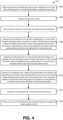
- the method 400 includes determining for each shock strut 116 for a particular time before the loading or the unloading of the aircraft 100 causes a second change in pressure of one or more of the shock struts 116 as indicated by the gas pressure data for the shock struts 116, a load delta value for each shock strut 116 at the particular time.
- the load delta value for the particular time is the load value based on the load sensor data at the particular time minus the load value based on the load sensor data at the first time.
- the method 400 also includes providing first output to one or more output devices.
- the first output includes information indicating the weight of the aircraft 100, the CG of the aircraft 100, or both.
- the one or more output devices include the display device 148 of the aircraft 100 visible to flight crew members.
- the one or more output devices can also include one or more devices external to the aircraft 100.
- the output can be provided to an electronic device 150 associated with a load master responsible for loading or unloading the aircraft 100.
- the loadmaster follows certain procedures for loading the aircraft 100 and the electronic device provides information to the load master about the load of the aircraft 100 and the CG via a second display device 152 coupled to the electronic device 150.
- the information may be based on general assumptions about the weight of the aircraft 100 at the start of loading and unloading and data regarding weight of cargo loaded on or removed from the aircraft 100.
- the electronic device 150 receives the weight and CG determined by the computer system 112 of the aircraft 100. If the weight and CG determined by the computer system 112 are not in general agreement with the weight and CG of the information, the load master can determine why there is not agreement before approving the aircraft 100 for flight.
- FIG. 5 is a flowchart illustrating a method 500 representing a life cycle of an aircraft 100 that includes the computer system 112 with the weight and balance instructions 136.
- the exemplary method 500 includes, at block 502, specification and design of the aircraft 100.
- the method 500 may include specification and design of the computer system 112 and parameters associated with the aircraft 100 that are subsequently used by the computer system 112 are set. Such parameters include angles from vertical of the landing gear 106 and effective ground contact locations of the landing gear 106.
- the method 500 includes material procurement, which may include procuring the computer system 112 and other components of the aircraft 100. Unsupported weights of components of landing gear 106 are determined after material procurement and saved for subsequent use by the computer system 112 to determine weight and CG of the aircraft 100.
- the method 500 includes, at block 506, component and subassembly manufacturing and, at block 508, system integration of the aircraft 100.
- the method 500 includes certification and delivery of the aircraft 100 and, at block 512, placing the aircraft 100 in service. Certification and delivery may include certification of the computer system 112 to place the aircraft 100 in service. While in service by a customer, the aircraft 100 may be scheduled for routine maintenance and service (which may also include modification, reconfiguration, refurbishment, and so on).
- the method 500 includes performing maintenance and service on the aircraft 100, which may include performing maintenance and service on the computer system 112 to determine if the weight and balance instructions 136 are providing useful data regarding the weight and balance of the aircraft 100.
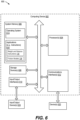
- the computing device 602 includes one or more processors 604.
- the processor 604 communicates with a system memory 606, one or more storage devices 608, one or more input/output interfaces 610, one or more communications interfaces 612, or a combination thereof.
- the system memory 606 includes non-transitory computer readable media, including volatile memory devices (e.g., random access memory (RAM) devices), nonvolatile memory devices (e.g., read-only memory (ROM) devices, programmable read-only memory, and flash memory), or both.
- the system memory 606 includes an operating system 614, which may include a basic input/output system for booting the computing device 602 as well as a full operating system to enable the computing device 602 to interact with users, other programs, and other devices.
- the processor 604 communicates with the one or more input/output interfaces 610 that enable the computing device 602 to communicate with one or more input/output devices 618 to facilitate user interaction.
- the input/output interfaces 610 can include serial interfaces (e.g., universal serial bus (USB) interfaces or Institute of Electrical and Electronics Engineers (IEEE) interfaces), parallel interfaces, display adapters, audio adapters, and other interfaces ("IEEE” is a registered trademark of The Institute of Electrical and Electronics Engineers, Inc. of Piscataway, New Jersey).
- the input/output devices 618 can include keyboards, pointing devices, displays (e.g., one or more monitors, one or more gauges, etc.), speakers, microphones, touch screens, rotatable selectors, levers, knobs, slides, switches, and other devices.
- the processor 604 detects interaction events based on user input received via the input/output interfaces 610. Additionally, the processor 604 sends a display to a display device via the input/output interfaces 610.
- the processor 604 can communicate with one or more devices 620 via the one or more communications interfaces 612.
- the one or more devices 620 can include external computing devices contacted via a communication network and controllers, sensors, and other devices coupled to the computing device 602 via wired or wireless local connections.
- the computing device 602 is the computer system 112
- the computing device 602 is configured to communicate via the interface 612 with devices external to the aircraft 100 such as an electronic device associated with a loadmaster responsible for loading or unloading the aircraft 100.
- the one or more communications interfaces 612 may include wired Ethernet interfaces, IEEE 802 wireless interfaces, other wireless communication interfaces, one or more converters to convert analog signals to digital signals, electrical signals to optical signals, one or more converters to convert received optical signals to electrical signals, or other network interfaces.
- a non-transitory, computer readable medium stores instructions that, when executed by one or more processors, cause the one or more processors to initiate, perform, or control operations to perform part or all of the functionality described above.
- the instructions may be executable to implement one or more of the operations or methods of FIGS. 1-4 .
- part or all of one or more of the operations or methods associated with FIGS. 1-4 may be implemented by one or more processors (e.g., one or more central processing units (CPUs), one or more graphics processing units (GPUs), one or more digital signal processors (DSPs)) executing instructions, by dedicated hardware circuitry, or any combination thereof.
- processors e.g., one or more central processing units (CPUs), one or more graphics processing units (GPUs), one or more digital signal processors (DSPs)
Landscapes
- Engineering & Computer Science (AREA)
- Aviation & Aerospace Engineering (AREA)
- Physics & Mathematics (AREA)
- General Physics & Mathematics (AREA)
- Mechanical Engineering (AREA)
- Force Measurement Appropriate To Specific Purposes (AREA)
Applications Claiming Priority (1)
| Application Number | Priority Date | Filing Date | Title |
|---|---|---|---|
| US18/463,073 US20250085195A1 (en) | 2023-09-07 | 2023-09-07 | Onboard aircraft weight and balance detection system |
Publications (1)
| Publication Number | Publication Date |
|---|---|
| EP4521079A1 true EP4521079A1 (de) | 2025-03-12 |
Family
ID=92708520
Family Applications (1)
| Application Number | Title | Priority Date | Filing Date |
|---|---|---|---|
| EP24198639.7A Pending EP4521079A1 (de) | 2023-09-07 | 2024-09-05 | Bordseitiges flugzeuggewichts- und -gleichgewichtsdetektionssystem |
Country Status (3)
| Country | Link |
|---|---|
| US (1) | US20250085195A1 (de) |
| EP (1) | EP4521079A1 (de) |
| CN (1) | CN119568421A (de) |
Families Citing this family (1)
| Publication number | Priority date | Publication date | Assignee | Title |
|---|---|---|---|---|
| US20250100678A1 (en) * | 2023-09-27 | 2025-03-27 | The Boeing Company | Landing gear assemblies, rotorcraft and rotorcraft methods |
Citations (1)
| Publication number | Priority date | Publication date | Assignee | Title |
|---|---|---|---|---|
| US20190186984A1 (en) * | 2017-12-14 | 2019-06-20 | C. Kirk Nance | Method for determining, predicting and correcting breakout friction errors influencing aircraft telescopic landing gear strut pressures |
Family Cites Families (2)
| Publication number | Priority date | Publication date | Assignee | Title |
|---|---|---|---|---|
| ATE156261T1 (de) * | 1992-02-07 | 1997-08-15 | C Kirk Nance | Anzeiger von gewicht und schwerpunkt von flugzeugen |
| US7967244B2 (en) * | 2006-11-16 | 2011-06-28 | The Boeing Company | Onboard aircraft weight and balance system |
-
2023
- 2023-09-07 US US18/463,073 patent/US20250085195A1/en active Pending
-
2024
- 2024-08-30 CN CN202411213015.6A patent/CN119568421A/zh active Pending
- 2024-09-05 EP EP24198639.7A patent/EP4521079A1/de active Pending
Patent Citations (1)
| Publication number | Priority date | Publication date | Assignee | Title |
|---|---|---|---|---|
| US20190186984A1 (en) * | 2017-12-14 | 2019-06-20 | C. Kirk Nance | Method for determining, predicting and correcting breakout friction errors influencing aircraft telescopic landing gear strut pressures |
Also Published As
| Publication number | Publication date |
|---|---|
| US20250085195A1 (en) | 2025-03-13 |
| CN119568421A (zh) | 2025-03-07 |
Similar Documents
| Publication | Publication Date | Title |
|---|---|---|
| EP4521079A1 (de) | Bordseitiges flugzeuggewichts- und -gleichgewichtsdetektionssystem | |
| CA2825500C (en) | Method of determining a turbulent condition in an aircraft | |
| EP2354005B1 (de) | Systeme und Verfahren zur Steuerung der Strukturkonturen | |
| US20150301530A1 (en) | Damage adaptive control | |
| IL273294B1 (en) | Metrology method and system | |
| CA2665963A1 (en) | Onboard aircraft weight and balance system | |
| CN112816051A (zh) | 传感器标定方法、称重方法、装置及搬运设备 | |
| CN115465468A (zh) | 用于预测支柱式起落架动着陆载荷的方法及系统 | |
| CN110941920A (zh) | 一种用于无人机飞行载荷数据计算与后处理的方法 | |
| US20240067361A1 (en) | Aircraft system operational testing | |
| WO2019117232A1 (ja) | 摩耗量予測方法、摩耗量予測装置、及び摩耗量予測プログラム | |
| CN110967145A (zh) | 一种实时检测飞机重心状态的方法和装置 | |
| CN111274648B (zh) | 一种民用飞机前缘襟翼的分布式飞行载荷设计方法 | |
| Bakunowicz et al. | Measuring structure deformations of a composite glider by optical means with on-ground and in-flight testing | |
| CN104677474A (zh) | 用于测量可变几何形状容器内的燃料质量的系统和方法 | |
| EP2672238A1 (de) | System zur Detektion der Grundbelastung und Verfahren zum Betrieb des besagten Systems | |
| CN106897474B (zh) | 一种飞机座舱压力控制系统控制性能评估方法 | |
| CN117763893A (zh) | 一种考虑结构变形的载荷动态处理方法 | |
| CN113673022B (zh) | 一种变形结构两点之间相对位移计算方法 | |
| EP4253930A1 (de) | Bestimmung eines lastzustands eines flugzeugs | |
| CN114566235B (zh) | 一种测定水凝胶软材料内部应力-应变场的方法 | |
| Skorupka | Laboratory investigations on landing gear ground reactions (load) measurement | |
| Kubit et al. | Experimental analysis of ultralight aircraft tyre behaviour under aircraft landing phase | |
| CN111488684A (zh) | 一种载荷平衡计算方法 | |
| US11267562B2 (en) | Method for detecting damage to a rotor of an aircraft |
Legal Events
| Date | Code | Title | Description |
|---|---|---|---|
| PUAI | Public reference made under article 153(3) epc to a published international application that has entered the european phase |
Free format text: ORIGINAL CODE: 0009012 |
|
| STAA | Information on the status of an ep patent application or granted ep patent |
Free format text: STATUS: THE APPLICATION HAS BEEN PUBLISHED |
|
| AK | Designated contracting states |
Kind code of ref document: A1 Designated state(s): AL AT BE BG CH CY CZ DE DK EE ES FI FR GB GR HR HU IE IS IT LI LT LU LV MC ME MK MT NL NO PL PT RO RS SE SI SK SM TR |
|
| STAA | Information on the status of an ep patent application or granted ep patent |
Free format text: STATUS: REQUEST FOR EXAMINATION WAS MADE |
|
| 17P | Request for examination filed |
Effective date: 20250813 |