EP4521055A1 - Plattenwärmetauscher mit 3d-flüssigkeitszirkulation - Google Patents
Plattenwärmetauscher mit 3d-flüssigkeitszirkulation Download PDFInfo
- Publication number
- EP4521055A1 EP4521055A1 EP24198991.2A EP24198991A EP4521055A1 EP 4521055 A1 EP4521055 A1 EP 4521055A1 EP 24198991 A EP24198991 A EP 24198991A EP 4521055 A1 EP4521055 A1 EP 4521055A1
- Authority
- EP
- European Patent Office
- Prior art keywords
- fluid
- fluid circulation
- circulation system
- heat exchanger
- plate
- Prior art date
- Legal status (The legal status is an assumption and is not a legal conclusion. Google has not performed a legal analysis and makes no representation as to the accuracy of the status listed.)
- Pending
Links
Images


Classifications
-
- F—MECHANICAL ENGINEERING; LIGHTING; HEATING; WEAPONS; BLASTING
- F28—HEAT EXCHANGE IN GENERAL
- F28F—DETAILS OF HEAT-EXCHANGE AND HEAT-TRANSFER APPARATUS, OF GENERAL APPLICATION
- F28F3/00—Plate-like or laminated elements; Assemblies of plate-like or laminated elements
- F28F3/08—Elements constructed for building-up into stacks, e.g. capable of being taken apart for cleaning
- F28F3/086—Elements constructed for building-up into stacks, e.g. capable of being taken apart for cleaning having one or more openings therein forming tubular heat-exchange passages
-
- F—MECHANICAL ENGINEERING; LIGHTING; HEATING; WEAPONS; BLASTING
- F24—HEATING; RANGES; VENTILATING
- F24H—FLUID HEATERS, e.g. WATER OR AIR HEATERS, HAVING HEAT-GENERATING MEANS, e.g. HEAT PUMPS, IN GENERAL
- F24H9/00—Details
- F24H9/14—Arrangements for connecting different sections, e.g. in water heaters
- F24H9/146—Connecting elements of a heat exchanger
-
- F—MECHANICAL ENGINEERING; LIGHTING; HEATING; WEAPONS; BLASTING
- F28—HEAT EXCHANGE IN GENERAL
- F28F—DETAILS OF HEAT-EXCHANGE AND HEAT-TRANSFER APPARATUS, OF GENERAL APPLICATION
- F28F2230/00—Sealing means
-
- F—MECHANICAL ENGINEERING; LIGHTING; HEATING; WEAPONS; BLASTING
- F28—HEAT EXCHANGE IN GENERAL
- F28F—DETAILS OF HEAT-EXCHANGE AND HEAT-TRANSFER APPARATUS, OF GENERAL APPLICATION
- F28F9/00—Casings; Header boxes; Auxiliary supports for elements; Auxiliary members within casings
- F28F9/02—Header boxes; End plates
- F28F9/026—Header boxes; End plates with static flow control means, e.g. with means for uniformly distributing heat exchange media into conduits
- F28F9/0265—Header boxes; End plates with static flow control means, e.g. with means for uniformly distributing heat exchange media into conduits by using guiding means or impingement means inside the header box
Definitions
- the present invention relates to the field of heat exchange between fluids, in particular implementing fluid separation within at least one of the fluids.
- thermodynamic cycle of the installation Increasing the thermal efficiency of a heat exchanger has a direct effect on the performance of the thermodynamic cycle of the installation, reducing the latter's primary energy consumption, and consequently the emissions and corresponding supply costs.
- the goal of optimizing the performance of a heat exchanger is achieved by adopting complex solutions where the original geometry of the part is specifically adapted to the specific application for which the installation is intended. Implementing such solutions is costly and limits the possible reuse of the exchanger for other applications.
- thermodynamic interactions may occur within the exchanger. It may then be necessary to orient the design of the heat exchanger in order to optimize either heat exchange or mass transfer.
- Concentric tube, tube bundle, coil, plate, mixing, or finned heat exchangers are known.
- the most widespread heat exchangers, due to the excellent heat transfer coefficients they achieve, are plate exchangers.
- Plate heat exchangers can be of the brazed or welded type or of the plate and gasket type.
- Welded plate heat exchangers are a single-piece design, meaning the plates cannot be separated after welding. Conversely, gasketed plate heat exchangers can be disassembled and then lengthened or shortened as needed, making them suitable for the desired application and facilitating exchanger maintenance.
- the flow of fluids in the heat exchanger can be single-phase or two-phase.
- the heat exchange benefits from a very favorable condition, because the phase change generally occurs at a constant temperature: the logarithmic temperature difference therefore increases considerably, reducing the necessary exchange surface.
- the two fluids are separated by a separating plate, usually made of metal.
- the thermal conductivity of the separating plate induces a resistance to heat transfer, which can be reduced by reducing its thickness or by using a separating plate made of a metal with high thermal conductivity, for example copper or aluminum rather than steel.
- Turbulence in the fluid circulation systems of each fluid is generally sought because it increases the thermal efficiency of the exchanger.
- US 5,392,849 A describes for example a superimposed plate exchanger in which the two fluids flow counter-current to each other. It comprises alternating solid plates to hollow plates where the fluid is distributed, flows and is collected before being discharged from the exchanger.
- CN 104748605 A describes a plate heat exchanger with microchannels. The heat exchange benefits from a magnetic field generated by electrodes inserted into a plate.
- CN 111780597 A describes a vacuum diffusion welded plate heat exchanger suitable for cross-flow between fluids.
- the exchanger according to the first main aspect of the invention is easily adaptable to the application for which it is intended. In addition, it is easy to maintain.
- the frame plate defines a housing in which different types of shaped plates or stacks of shaped plates can be housed. Thus, a used shaped plate can be replaced while keeping the frame plate in place if the latter is still in good working order.
- the exchanger is to be integrated into an installation for which the application is different from that initially envisaged, it is possible to design a shaped plate or a stack of shaped plates with a fluid circulation system of a shape specifically adapted to the application, without it being necessary to modify the separation plate and/or the frame plate.
- the shaped plate or the stack of shaped plates can be obtained from cutting techniques that are simpler to implement and less expensive than the machining or stamping techniques usually used to produce the heat exchangers of the prior art.
- each shaped plate has a thickness less than the frame plate.
- each shaped plate has a low thickness, allowing optimal heat transfer without it being required to contribute to the mechanical strength of the heat exchanger, this function being provided by the frame plate of greater thickness.
- the thickness of a component is defined and measured along the longitudinal axis of the heat exchanger.
- the heat exchanger comprises a groove separating the frame plate and the inner part from each other, the width of the groove preferably being constant.
- the groove may completely surround the periphery of the inner part.
- the heat exchanger has a seal, preferably an O-ring, arranged in the groove and compressed by the adjacent separating plates. This reinforces the seal between the separating plates and the corresponding exchange module, reducing the risk of fluid leakage. In addition, the seal can easily be removed when replacing or changing the inner part.
- the gasket can be extruded or overmolded. It can be made of a polymer material, for example chosen from ethylene propylene diene monomer (EPDM), or polytetrafluoroethylene (PTFE). It can have a Shore hardness of between 70 and 80.
- EPDM ethylene propylene diene monomer
- PTFE polytetrafluoroethylene
- the inner part can be fixed, for example glued, brazed or welded, in particular by diffusion welding, to the frame plate.
- the frame plate and the form plate(s) can be made of different materials. For example, it is possible to choose a material with low mechanical properties and good thermal properties to form the form plate(s).
- the frame plate may be made of a material having a modulus of elasticity and/or a breaking strength greater than the modulus of elasticity and/or the breaking strength, respectively, of the constituent material of the shaped plate(s).
- the frame plate contributes more to the rigidity and/or the mechanical strength of the exchanger than the inner part.
- the solid area of the or each form plate and the frame plate may have different surface roughnesses.
- the frame plate and/or the shape plate(s) may be metallic, for example made of steel, particularly stainless steel, or made of aluminium, copper or titanium.
- the shaped plate(s) may comprise a material that catalyzes a chemical reaction upon contact with a component of the first and/or second fluid.
- the frame plate having in particular the function of ensuring the spacing between two consecutive separation plates, it can have a low thermal conductivity, for example less than 50 Wm -1 .K -1 , to avoid participating in the heat transfer.
- the second exchange module may comprise a third fluid circulation system fluidically disconnected from the second fluid circulation system, the second and third fluid circulation systems being defined by different portions of the hollowed-out zone(s) of the corresponding interior part.
- the same interior part may define different and separate flow zones for different fluids.
- the second exchange module may comprise a third fluid circulation system fluidically disconnected from the second fluid circulation system, the corresponding frame plate comprising a second window in which a second interior part is arranged which delimits the third fluid circulation system.
- the heat exchanger according to the second main aspect of the invention thus defines, by a simple stacking of the shaped plates between two adjacent separation plates and in the plane and/or in the thickness of the stack, a fluid circulation system of complex two-dimensional or, preferably, three-dimensional shape.
- the invention also overcomes the limitations encountered in the stamped plate exchangers of the prior art, where the channels have a geometry defined by the shape of the stamped reliefs.
- the fluid circulation system has, in at least one longitudinal sectional plane, different profiles in at least two different positions along the transverse axis of said sectional plane, perpendicular to the longitudinal axis.
- the profile in a position along said transverse axis may comprise the rank of the hollowed-out zone(s) in the stack and/or the height of the fluid circulation system in said position and/or the number of hollowed-out zones in said position.
- the fluid circulation system may comprise portions that extend along different axes. It may comprise at least two portions that extend along axes contained in a transverse plane and that are different from each other. It may comprise at least two portions that extend along axes contained in a longitudinal plane and that are different from each other.
- a longitudinal plane contains the longitudinal axis.
- a transverse plane is defined by two transverse axes that are each perpendicular to the longitudinal axis. A transverse plane is therefore perpendicular to a longitudinal plane.
- the fluid circulation system may comprise at least one main path which divides upstream into several secondary paths which join downstream.
- the fluid circulating in the fluid circulation system may follow different paths inside the corresponding exchange module. This makes it possible to vary the fluidic conditions of the flow by changing the shape of the passage section of the circulation system. fluidic along its path. It is thus possible to generate phase separation within each secondary path and/or self-balancing of pressures and/or fluid flow rates between the secondary paths.
- the fluid flow system may include, when viewed in a longitudinal sectional plane, a meandering portion extending between adjacent divider plates.
- the length and/or width of the form plates and the separation plates may be equal.
- the heat exchanger according to the third main aspect of the invention has the advantage of great compactness, the heat exchange and phase separation taking place within the first and second exchange modules.
- the exchanger comprises a supply conduit of the first fluid circulation system opening into an inlet opening of the first fluid and a discharge conduit of the first fluid opening into an outlet opening of the first fluid, the third fluid circulation system being closer to said inlet opening of the first fluid than to the outlet opening of the first fluid.
- the third system fluid circulation is then closer to the coldest zone of the first exchange module, which facilitates cooling, and for example the liquefaction of the second fluid component.
- the exchanger is configured so that the second fluid component, after changing state, flows countercurrently to the first fluid in the first fluid circulation system toward the third fluid circulation system.
- the second fluid component which has changed from the liquid state to the gaseous state under the effect of the heat exchange with the second fluid, flows in the gaseous state against the flow of the first fluid which contains the second liquid component in the liquid state.
- the heat exchanger preferably includes a third fluid circulation system discharge conduit for purging the second fluid component from the exchanger.
- At least one of the first and second exchange modules consists of a shaped plate consisting of at least one hollowed-out zone passing through the thickness of the shaped plate from one side to the other and a surrounding solid zone of constant thickness, the first fluid circulation system on the one hand or the second fluid circulation system and/or the third fluid circulation system on the other hand being formed respectively in the hollowed-out zone and delimited transversely by the surrounding solid zone and longitudinally by the separation plates adjacent to said module.
- the heat exchanger may comprise one or more of the following optional features.
- the first and second exchange modules are preferably arranged alternately one after the other along the longitudinal axis.
- the recessed area is formed by cutting.
- the recessed area is formed by laser beam cutting.
- the first and second fluid circulation systems are preferably longitudinally delimited by the separation plates which sandwich the first and second adjacent exchange modules respectively and which are in contact with said first and second exchange modules respectively.
- At least one, preferably each of the first, second and, where appropriate, third fluid circulation systems comprises at least one channel, preferably a plurality of channels, and/or a fluid distribution chamber for supplying fluid to the channel(s) and/or a collection chamber into which the channel(s) open downstream.
- the channels may extend parallel to each other, for example parallel to the length of the interior part.
- the channel(s) may form a serpentine that extends in the median plane of the interior part.
- the form plate(s) and/or the separation plate and/or the frame plate are preferably flat and have parallel faces.
- the separation plate can have a thickness less than or equal to 2.0 mm, in order to maximize thermal exchanges, and optionally greater than or equal to 0.5 mm.
- the separation plate may have a roughness suitable for facilitating the establishment of a turbulent flow of the first fluid or the second fluid.
- the frame plate can have a thickness between 1 and 10 mm.
- each shaped plate of the stack may have a thickness of less than 3 mm, or even less than 2 mm, or even less than 1 mm.
- the shaped plates can have the same thickness.
- the stack may comprise at least two identically shaped plates.
- the identically shaped plates are each asymmetrical, one of the shaped plates being arranged symmetrically to the other shaped plate with respect to a longitudinal plane.
- asymmetric we mean that a plate has at most a single longitudinal plane of symmetry.
- an asymmetric plate can be symmetrical about a transverse median plane.
- At least two shaped plates of the stack are different.
- the stack can consist of more than two, or even more than five, or even more than ten shaped plates.
- a high number of shaped plates allows the shape of the fluid circulation system to be refined.
- the separation plate on the one hand and the form plate(s), and/or, where appropriate, the frame plate on the other hand, may be made of different materials.
- the separation plates have a thickness less than the thickness of each of the first exchange modules and/or the thickness of each of the second exchange modules.
- the exchanger comprises end plates arranged longitudinally at the ends of the exchanger and which sandwich the plurality of first and second exchange modules and the plurality of separation plates.
- one and/or the other of the end plates comprises an inlet opening for the first fluid and/or an outlet opening for the first fluid and/or an inlet opening for the second fluid and/or an outlet opening for the second fluid and/or, where appropriate, an outlet opening for the second fluid component.
- the first exchange modules are all identical and/or the second exchange modules are all identical. This facilitates the manufacture and maintenance of the heat exchanger.
- the heat exchanger may be of the welded type.
- the first exchange modules and/or the second exchange modules may be welded onto the separation plates.
- the heat exchanger is of the "gasket” type, which facilitates its maintenance, for example by only replacing the used separation plate(s), form plate(s) or frame plate(s).
- the heat exchanger comprises compression means for compressing the first and second exchange modules and the separation plates so as to ensure the sealing of each of the first, second and, where appropriate, fluid circulation systems.
- the end plates may be provided with holes, and the exchanger comprises connecting rods engaged in the holes and which connect the end plates. The connecting rods are bolted onto the end plates and compress said superposition.
- the flow of the second fluid component occurs counter-currently to the flow of the first fluid in the first fluid circulation system.
- the method may include cooling the second fluid component after the third fluid component leaves the heat exchanger and prior to the second fluid component flowing out of the heat exchanger.
- the first fluid is introduced in the liquid state into the first fluid circulation system, and the second component is in the gaseous state after the phase change due to the heating of the first fluid by heat transfer with the second fluid.
- the first fluid component is preferably maintained in the liquid state during its flow in the first fluid circulation system.
- the first fluid component may be water and the second fluid component may be ammonia.
- the second fluid may be water, in particular glycolated water, or oil.
- the first fluid and the second fluid may flow countercurrently in the first and second fluid circulation systems, in order to maximize the heat exchange between them.
- the invention also relates to a thermodynamic installation comprising an exchanger according to the invention, in particular according to the third aspect of the invention.
- FIG. 1 schematically, an example of a plate heat exchanger 1, in particular such as the invention.
- This exchanger is intended for the exchange of heat between two fluids, one of the fluids entering the heat exchanger at a lower temperature than the other fluid.
- the exchanger 1 comprises an end plate 3 provided with an inlet opening 5 for the first fluid, an inlet opening 7 for the second fluid, a first fluid outlet opening and a second fluid outlet opening 11 for introducing the first and second fluids into the exchanger and extracting them from it.
- the heat exchanger further comprises first 13 and second 15 exchange modules which are superimposed on each other along a longitudinal axis X.
- the first and second are arranged alternately one after the other along the longitudinal axis. They each have a substantially parallelepiped and slender shape which extends transversely to the longitudinal axis X.
- each of the first 13 and second 15 exchange modules has transversely extending faces 17 which are planar and parallel.
- the exchanger further comprises separation plates 19 which are each arranged between first and second adjacent exchange modules. Each separation plate is further in contact with the first and second exchange modules which are adjacent to it.
- Each separating plate 19 extends transversely to the longitudinal axis and preferably has flat and parallel faces.
- the first and second exchange modules each define a first fluid circulation system 21 for the flow of the first fluid and a second fluid circulation system 23 for the flow of the second fluid.
- the heat exchanger further comprises a supply conduit 25 of the first fluid circulation system and a supply conduit 27 of the second fluid circulation system for delivering the first and second fluids respectively into the first and second fluid circulation systems.
- the supply conduit of the first fluid circulation system and the supply conduit of the second fluid circulation system each open at one of their ends into the inlet opening 5 of the first fluid and into the inlet opening 7 of the second fluid.
- the supply conduit 25 of the first fluid circulation system and the supply conduit 27 of the second fluid circulation system are formed for example by holes formed in the first exchange modules and in the separation plates. They are shaped so as to be fluidically disconnected from each other, and to avoid mixing between the first and second fluids.
- the heat exchanger further comprises a discharge conduit 29 of the first fluid circulation system and a discharge conduit 31 of the second fluid circulation system for purging the first and second fluids respectively from the first and second fluid circulation systems.
- the discharge conduit 29 of the first fluid circulation system fluidically connects the first, respectively second, fluid circulation system to the outlet opening 9 of the first fluid, respectively to the outlet opening 11 of the second fluid.
- the supply and discharge conduits of the first fluid circulation system and the supply and discharge conduits of the second fluid circulation system are each formed, for example, by holes formed in the first and second exchange modules and in the separation plates. They are shaped to form disconnected fluid circulation paths between the inlet openings and the openings outlet for each of the first and second fluids.
- the heat exchanger is shaped so that the first and second fluids do not come into contact and do not mix.
- the supply and discharge conduits of the first fluid circulation system and the supply and discharge conduits of the second fluid circulation system further open respectively into the first fluid circulation system and into the second fluid circulation system arranged in each of the first and second exchange modules respectively.
- each of the first exchange modules is separated from the two exchange modules which are adjacent to it on either side of the longitudinal axis, by a separation plate 19 and vice versa.
- each separation plate that is superimposed on the first fluid flow system and the second fluid flow system adjacent thereto is solid.
- the separation plates 19 that sandwich a first exchange module 13 and that are in contact with said first exchange module fluidly isolate the first fluid circulation system 21 from the second fluid circulation systems that are formed in the adjacent second exchange modules 15, and vice versa.
- the first and second fluids are introduced respectively through the inlet opening 5 of the first fluid and through the inlet opening 7 of the second fluid into the exchanger. They flow respectively into the supply conduit 25 of the first fluid circulation system and into the supply conduit 27 of the second fluid circulation system. They then circulate in each of the first 21 and second 23 fluid circulation systems respectively and exchange heat through the separation plate that said systems sandwich. They are then collected respectively by the discharge conduit of the first fluid circulation system and the discharge conduit of the second fluid circulation system before exiting the exchanger through the outlet opening of the first fluid and the second fluid opening respectively.
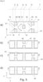
- an exchange module 33 which can be a first exchange module 13 for the first fluid and/or a second exchange module 15.
- the exchange module is arranged between and in contact with two separation plates 19 which separate it longitudinally from the adjacent exchange modules 35.
- the exchange module 33 comprises a frame plate 37 which extends transversely to the longitudinal axis X.
- the frame plate 37 has two flat and parallel faces.
- the window 39 defines a through window 39 which passes through the thickness of the frame plate from one side to the other.
- the window 39 thus opens out through the two opposite faces of the frame plate.
- the exchange module 33 further comprises an inner part 41 which is housed entirely in the window.
- the inner part 41 and the frame plate 37 are of equal thickness e.
- the inner part 41 and the frame plate 37 are both in contact by their opposite faces with the adjacent separation plates 19.
- the inner part 41 comprises at least one shaped plate 43.
- a single shaped plate 43 whose thickness is equal to the thickness e of the frame plate.
- Such an exemplary embodiment is illustrated for example in the figures 9 to 13 , which will be described later.
- the inner part comprises a stack 45, along the longitudinal axis, of several shaped plates 43 on top of each other.
- it comprises two shaped plates, but it can comprise a greater number.
- the single shaped plate or each shaped plate of the stack has two flat and parallel faces. It further consists of at least one hollowed-out area 47 surrounded, at least partially, or even entirely, by a surrounding solid area 49.
- the fluid circulation system 50 of the exchange module which is where appropriate the first 21 or the second 23 fluid circulation system, is defined by the zone(s) hollowed out 47 of the single shaped plate or stack.
- the shaped plate 43a comprises a hollowed-out area 47 in the form of a main groove 51 and parallel transverse secondary grooves 53 which each extend from the same side of the main groove 51.
- the other shaped plate 43b superimposed on the shaped plate 43a has a pattern substantially identical to that of the shaped plate 43a except that it is rotated by an angle of 90° relative to the longitudinal axis.
- the superposition of the hollowed-out 47 and/or solid 49 areas of the shaped plates 43 of the plurality defines a fluid circulation system with different circulation paths which extend in the thickness and transversely in the interior part.
- the fluidic system formed in the exchange module 33 is delimited longitudinally by the facing faces of the opposite separation plates 19 which sandwich the exchange module 33, and transversely by the solid zone(s) 49 of the shaped plate(s) 43 as well as, optionally, by the lateral face 55 of the window 39 of the frame plate 37.
- the exchange module 33 consists of at least one shaped plate 43 consisting of at least one hollowed-out zone 47 and a surrounding solid zone 49 completely surrounding the hollowed-out zone.
- the module 33 comprises a stack 45 of shaped plates 43 ab extending along the longitudinal axis.
- the superposition of the hollowed-out 47 and/or solid 49 zones of the shaped plates 43 of the stack defines a fluid circulation system with different circulation paths which extend longitudinally and transversely in the exchange module 33.
- the heat exchanger 33 may comprise exchange modules according to the first embodiment and/or according to the second embodiment. For example, all the first exchange modules are according to the first embodiment and all the second exchange modules are according to the second embodiment or vice versa.
- the exchanger may include a groove 57, preferably of constant width, extending transversely between the inner part 41 and the frame plate 37.
- a seal 59 preferably an O-ring, may be disposed in the groove, as illustrated in the Figure 4 The seal may project longitudinally from the groove 57, so as to be compressed by the adjacent forming plates and/or separating plates.
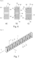
- FIG. 5 illustrates an example of a stack of a heat exchanger according to the second aspect of the invention.
- the hollow zone of the intermediate shaped plate is superimposed on the solid zones of the shaped plates superimposed on it.
- the profile of the fluid circulation system thus evolves from a high thickness profile to a lower thickness profile.
- the fluid circulation system has a profile identical to the profile at the abscissa Yi.
- hollowed-out areas of the lower and upper shaped plates are superimposed on the solid area of the intermediate shaped plate.
- the system comprises a main path 59 which divides into secondary paths 61 which meet downstream at the abscissa Y 5 , as indicated by the arrows F.
- the fluid circulation system 50 thus comprises portions which extend along the thickness of the stack which are extended by portions which extend parallel to the median plane of the stack.
- FIGS. 5 b) to 5 d) represent each of the lower, intermediate and upper shaped plates, observed along the longitudinal axis.
- the variation profile of the fluidic system also included the variation in width, measured along the Z axis perpendicular to the longitudinal X and transverse Y axes, of the fluidic system, which also includes portions which extend along axes different from the median plane of the stack.
- the exchange module 33 can define several fluid circulation systems 50.
- this is achieved by providing that different portions 63,65 of a shaped plate 43 are supplied by different supply and discharge conduits.
- the frame plate 37 comprises two windows 39 in which are housed respectively two plates of shapes 43, for example for the flow of two different fluids within the same exchange module.
- Other examples similar to that illustrated on the Figure 6 c) are illustrated on the figures 7 to 13 .
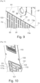
- THE figures 7 to 13 represent another example of a heat exchanger 1 according to the invention, adapted to separate, under the effect of the heat exchange between the first and second fluids, first and second different fluid components which constitute the first fluid.
- first exchange modules 13 and a plurality of identical second exchange modules 15 which extend along a vertical Y axis.
- the first and second exchange modules are arranged alternately with each other along the longitudinal X axis, which is horizontal.
- Identical separation plates 19 are further arranged between each pair of first and second modules. It finally comprises two end plates 3 at each longitudinal end and clamping means, not illustrated, which longitudinally compress the superposition of the first and second exchange modules and separation plates.
- the inner part 71 has an outer contour 75 which is homothetic to the lateral contour 77 of the window, such that it is arranged at a constant distance from the contour of the window.
- a groove 79 is thus delimited between the inner part and the frame plate.
- the two plates of form 73a-b are identical.
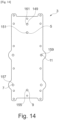
- Each shaped plate 73a-b has a generally perpendicular shape which extends at its two ends in its length by triangular-shaped parts. It comprises a solid zone 81 which comprises a frame 83 defining a side wall of the shaped plate. The solid zone 81 further comprises lower 85 and upper 87 bands which each extend between two opposite lateral edges 89 of the shaped plate and a central portion 91 which represents more than 70% of the area of the solid zone.
- a “lower” structure is arranged at a lower height along the vertical axis Y than an “upper” structure.
- the central portion 91 is arranged between the lower 85 and upper 87 bands. It frames a plurality of hollowed-out zones 93 in the form of parallel straight grooves and extending along the length of the shaped plate.
- each shaped plate 73a-b defines lower 95 and upper 97 hollowed-out areas on either side of the central portion, along the length of the frame plate.
- These lower and upper hollowed-out portions each represent more than 10% of the shaped plate area. They extend from one lateral edge 89 to the other.
- the superposition of the lower and upper hollowed-out areas respectively of the two shaped plates of the stack thus defines a distribution chamber 99 for the first fluid and a collection chamber 101 for the first fluid respectively.
- Each shaped plate 73a-b is asymmetrical along a median longitudinal plane. They are arranged relative to each other in such a way that one is the image of the other by a rotation of 180° around a transverse axis Y', vertical, parallel to the length direction of said shaped plates.
- the superposition of said shaped plates 73a-b defines a complex fluid circulation path composed of parallel channels 103 extending along the length of the inner part and winding through the thickness of the inner part, grooves of one of the shaped plates being superimposed on the central portion of the other shaped plate and vice versa.
- Each channel 103 is supplied upstream by the distribution chamber 99 of the first fluid and opens downstream into the collection chamber 101 of the first fluid.
- the first module comprises a sealing gasket 59 arranged in the groove.
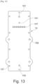
- the second exchange module 15, illustrated on the Figure 12 is different from the first exchange module 13.
- It comprises a frame plate 105 provided with two through windows 107, 109 and disjointed from each other, in which two interior parts 111, 113 are arranged respectively.
- the first inner part 111 is formed from a longitudinal stack 115 of two shaped plates 117a-b, and the second inner part 113 consists of a single shaped plate 119, as is more particularly visible in the Figure 10 .
- the first 111 and second 113 interior pieces are of equal thickness to the frame plate 105.
- the first and second interior pieces are each homothetic to the contours of the windows in which they are arranged and are each separated by a groove from the surrounding window in which a sealing O-ring is arranged.
- the form plates 117a-b of the first inner part 111 are identical and asymmetrical. They are arranged relative to each other in such a way that one is the image of the other by a rotation of 180° around a transverse axis Y", vertical, parallel to the length direction of said frame plates.
- Each form plate 117 consists of a surrounding solid area 121 which frames hollowed-out areas 123 which together delimit a serpentine-shaped groove 125 which extends between two transverse edges 127 of the form plate.
- the groove is interrupted by reinforcements 129 transverse to the axis of extension of the groove 125.
- the grooves of the two form plates 117a-b are superimposed on each other, thus defining a second fluid circulation system 23, in the form of a channel, for the flow of the second fluid.
- the transverse reinforcements 129 superimposed on a hollowed-out area of the other shaped plate induce a deviation of the flow of the second fluid according to the thickness of the stack 115.
- the second inner part 113 consists of a pentagonal shaped plate 119 with a thickness equal to the thickness of the frame plate 105.
- the shaped plate comprises a solid zone 131 whose area is less than 20% of the area covered by the shaped plate.
- the solid zone 131 further comprises an outer frame 133 and fingers 134 which extend perpendicularly from an edge 135 of the outer frame 133, parallel to each other. It further comprises a cord 137 which connects said edge 135 to an opposite vertex 139 of the pentagon.
- the solid zone 131 thus surrounds two hollow zones 141 which define a third fluid circulation system 145, which may be a deflection chamber 146 as will be apparent later.
- Each separation plate 19 which separates the first 13 and second 15 adjacent exchange modules has holes 147 which pass right through its thickness and which put the third fluid circulation system 145 in fluid connection with the first fluid circulation system 21.
- the holes are in the form of slots which are superimposed on the spaces between the fingers 133 of the inner part 113 and on the distribution chamber 99 of the first fluid circulation system.
- one of the end plates 3 comprises an inlet opening 5 for the first fluid and an outlet opening 9 for the first fluid for introducing the first fluid and extracting the first fluid component from the exchanger, as will be described below. It further comprises an inlet opening 7 for the second fluid and an outlet opening 11 for the second fluid for introducing and extracting the second fluid from the heat exchanger. Finally, it comprises an outlet opening 149 for the second fluid component for extracting the second fluid component from the exchanger.
- one or more of the aforementioned inlet openings and/or outlet openings may be arranged on the other end plate.
- the inlet opening 5 of the first fluid is extended by a supply conduit 151 of the first fluid circulation system 21 which opens into the distribution chamber 99 of the first fluid circulation system.
- the supply conduit 151 of the first fluid circulation system is delimited by the repetition of the assembly formed by the longitudinal superposition of a through hole formed in the end plate which opens onto the inlet opening of the first fluid, of a through hole drilled in the bead of the shaped plate of the second inner part of the second exchange module, of a through hole formed in the separation plate and of a through hole formed in the inner part of the first exchange module.
- This assembly is repeated longitudinally so that all the first exchange modules 13 are supplied in parallel with the first fluid.
- the inner part 71 of the first exchange module 13 comprises a notch 153 formed in the upper strip which fluidically connects the supply conduit of the first fluid circulation system to the first fluid distribution chamber.
- the outlet opening 9 of the first fluid is extended by an evacuation conduit 155 of the first fluid circulation system 21 which opens into the collection chamber 101 of the first fluid circulation system.
- the discharge conduit 155 of the first fluid circulation system is delimited by the repetition of an assembly formed by the longitudinal superposition of a through hole provided in the end plate which opens onto the outlet opening of the first fluid, of a through hole drilled in the frame plate of the second exchange module, of a through hole formed in the separation plate. This assembly is repeated longitudinally so that all the first exchange modules are purged in parallel of the first fluid.
- the supply duct of the second fluid circulation system opens into the second fluid circulation system. It is delimited by the superposition of an assembly formed by the longitudinal superposition of a through hole provided in and on the periphery of the end plate and which opens onto the inlet opening of the second fluid and, where appropriate, of a through hole drilled in the frame plate of the first exchange module and of a through hole formed in the separation plate. This set is repeated longitudinally so that all the second exchange modules are supplied in parallel with the second fluid.
- the inlet opening 7 of the second fluid is extended by a supply conduit 157 of the first fluid circulation system 21.
- the supply conduit 157 of the second fluid circulation system opens into the second fluid circulation system 23. It is delimited by the repetition of an assembly formed by the longitudinal superposition of a through hole formed in and at the periphery of the end plate 3 and which opens onto the inlet opening of the second fluid 7 and, where appropriate, of a through hole drilled in the frame plate of the first exchange module and of a through hole formed in the separation plate. This assembly is repeated longitudinally so that all the second exchange modules are supplied in parallel with the second fluid.
- the outlet opening 11 of the second fluid is extended by an evacuation conduit 159 of the second fluid circulation system 23.
- the discharge conduit 159 of the second fluid circulation system opens into the second fluid circulation system 23. It is delimited by the repetition of an assembly formed by the longitudinal superposition of a through hole formed in and at the periphery of the end plate 3 and which opens onto the outlet opening of the second fluid 11 and, where appropriate, of a through hole drilled in the frame plate of the first exchange module and of a through hole formed in the separation plate 19. This assembly is repeated longitudinally so that all the second exchange modules are purged of the second fluid in parallel.
- outlet opening 149 of the second fluid component is extended by an evacuation conduit 161 of the third fluid circulation system 145.
- the discharge conduit 161 of the third fluid circulation system opens into the third fluid circulation system. It is delimited by the superposition of an assembly formed by the longitudinal superposition of a through hole provided in the end plate and which opens onto the outlet opening of the second fluid component and, where appropriate, of a through hole drilled in the interior part of the first exchange module, and of a through hole formed in the separation plate. This assembly is repeated longitudinally so that all the second exchange modules are purged in parallel of the second fluid component.
- the first fluid comprises a first fluid component, for example water, and a second fluid component, for example ammonia. When it enters the exchanger, the first fluid is entirely liquid.
- the first fluid enters the heat exchanger through the first fluid inlet 5. It flows into the supply conduit 151 of the first fluid circulation system and then enters the distribution chamber 99 of the first heat exchange module 21 where it is distributed in the different parallel channels 103 of the central portion 91 towards the collection chamber 101.
- the second fluid flows counter-currently to the first fluid. It enters the heat exchanger through the second fluid inlet opening 7 and flows into the second fluid supply conduit 157. It then enters the second exchange module 23 where it circulates in the second fluid circulation system in the form of a serpentine to the discharge conduit of the second fluid circulation system.
- the first fluid and the second fluid exchange heat in the portions of the first and second fluid circulation systems which are longitudinally superimposed and fluidically disconnected by the separating plate 19 which separates them.
- the amount of heat supplied to the first fluid is sufficient to induce a phase transformation, from liquid to gas, of only the second fluid component.
- a phase transformation from liquid to gas
- ammonia changes from liquid to gas and water remains in liquid.
- the first fluid component accumulates in the collection chamber 101 before being discharged through the outlet opening 9 of the second fluid circulation system.
- the second fluid component in the gaseous state flows countercurrently in the first circulation system under the effect of an Archimedes thrust in the central portion 91 of the first fluid circulation system.
- the flow of the second fluid component is constrained by the volume of the first fluid contained in the distribution chamber 99 of the first fluid.
- the second fluid component is then diverted through the slots 147 of the separation plate and enters the diversion chamber 146 in the second exchange module.
- the diversion chamber 146 thus makes it possible to collect the second fluid component by bypassing the distribution zone 99 of the first fluid in order to extract it from the second exchange module via the discharge conduit of the third fluid system to the corresponding outlet opening.
- FIG. 15 illustrates another example of a heat exchanger that differs from that shown in the figures 7 to 14 by the following characteristics.
- Each shaped plate 73 of the inner part 71 of the first exchange module 13 comprises a central strip 162 extending between two opposite lateral edges 89 of the shaped plate.
- the central strip is provided with a hole through which the supply conduit 151 of the first fluid opens into the first fluid circulation system 21.
- Each shaped plate further comprises a central portion 91 which is interrupted by a distribution chamber of the first fluid in which the central strip.
- the central strip is arranged between and at a distance from the lower 91 i and upper 91 s parts of the central portion 91.
- a distribution chamber 99 of the first fluid is defined between the central strip and the lower central portion 91;.
- the second exchange module 15 comprises first 107, second 109, and third 163 windows respectively receiving first 111, second 113, and third interior rooms 165.
- the first 107 and third 163 windows are arranged on either side of the second 109 window.
- the second fluid circulation system 23 is formed by the first interior part 111 which is a single shaped plate 117 comprising a hollowed-out zone in the form of a coil which extends between the supply ducts 27 and evacuation ducts 31 of the second fluid circulation system.
- the second fluid circulation system may be defined by a stack of shaped plates as described in figures 7 to 14 .
- the second interior part 113 is a plate of rectangular and perforated shape 119, which has an external frame 133 delimiting a deflection chamber 146, superimposed on the distribution chamber 99 of the first fluid and on lower 147 i and upper 147 s through slots arranged in the separation plate 19.
- the third inner part 165 is a shaped plate 167 having a hollowed-out area having a serpentine shape, which thus defines a fourth fluid circulation system 173.
- the frame plate 67 of the first exchange module 13 and the separation plate 19 are provided with superimposed through holes which define supply 169 and discharge 171 conduits for a fluid flowing in the fourth fluid circulation system.
- a first fluid being a mixture of a first fluid component, for example liquid water, and a second fluid component, for example liquid ammonia, is introduced into the first fluid circulation system 21 through the supply conduit 151 where it is distributed in the distribution chamber 99 and then flows, under the effect of gravity, towards the collection chamber 101.
- a second fluid, hotter than the first fluid is circulated counter-currently in the second fluid circulation system 23 between the corresponding inlet 27 and outlet 29 conduits.
- the first fluid is then heated under the effect of heat transfer with the second fluid, which induces a phase transformation of the second fluid component, for example the vaporization of the ammonia.
- the second fluid component then rises up the lower part 91 i of the central portion counter-currently to the flow of the first fluid. Its flow is then blocked by the first fluid contained in the distribution chamber 99. It is thus diverted through the lower slot 147 i into the diversion chamber 146.
- the second fluid component then rises through the deflection chamber 146 and again passes through the separation plate 19 through the upper slot 147 s . It flows then in the upper part 91 s of the central portion towards the outlet opening 149 of the second fluid component to extract the second fluid component from the exchanger.
- a fluid for example identical to the second fluid, and colder than the second fluid component is circulated countercurrently to the second fluid component, in the fourth fluid circulation system 173 between the supply 169 and discharge 171 conduits of the fourth fluid circulation system.
- the second fluid component is thus cooled during its flow between the third fluid circulation system 145 and the outlet 149 of the second fluid component.
- the cooling by heat exchange with the fluid circulating in the fourth fluidic system 173 causes the condensation of the first fluid component which is thus separated from the second fluid component.
- the first fluid component then recirculates in the liquid state under the effect of gravity through the upper part 91s then lower part 91i of the central portion to the collection chamber 101 of the first liquid.
- the second fluid component for example ammonia
- ammonia thus separated is of high purity.
Landscapes
- Engineering & Computer Science (AREA)
- Physics & Mathematics (AREA)
- Thermal Sciences (AREA)
- Mechanical Engineering (AREA)
- General Engineering & Computer Science (AREA)
- Chemical & Material Sciences (AREA)
- Combustion & Propulsion (AREA)
- Heat-Exchange Devices With Radiators And Conduit Assemblies (AREA)
Applications Claiming Priority (1)
| Application Number | Priority Date | Filing Date | Title |
|---|---|---|---|
| FR2309504A FR3152869B1 (fr) | 2023-09-08 | 2023-09-08 | Echangeur de chaleur à plaques avec circulation de fluide 3D |
Publications (1)
| Publication Number | Publication Date |
|---|---|
| EP4521055A1 true EP4521055A1 (de) | 2025-03-12 |
Family
ID=88965613
Family Applications (1)
| Application Number | Title | Priority Date | Filing Date |
|---|---|---|---|
| EP24198991.2A Pending EP4521055A1 (de) | 2023-09-08 | 2024-09-06 | Plattenwärmetauscher mit 3d-flüssigkeitszirkulation |
Country Status (3)
| Country | Link |
|---|---|
| US (1) | US20250085022A1 (de) |
| EP (1) | EP4521055A1 (de) |
| FR (1) | FR3152869B1 (de) |
Citations (8)
| Publication number | Priority date | Publication date | Assignee | Title |
|---|---|---|---|---|
| US2379671A (en) * | 1942-12-31 | 1945-07-03 | Walker Wallace Inc | Heat exchanger |
| FR2184536A1 (en) * | 1972-05-19 | 1973-12-28 | Anvar | Very low temperature heat exchangers - partic suitable for helium 3 and helium 4 |
| DE4238192A1 (de) * | 1992-11-12 | 1994-05-19 | Hoechst Ceram Tec Ag | Durchlässige Strukturen |
| US5392849A (en) | 1990-09-28 | 1995-02-28 | Matsushita Refrigeration Company | Layer-built heat exchanger |
| EP0724127A2 (de) * | 1995-01-27 | 1996-07-31 | Diana Giacometti | Platten - Stoff- und Wärmetauscher |
| EP0780654A1 (de) * | 1995-12-19 | 1997-06-25 | MERLONI TERMOSANITARI S.p.A. | Einrichtung für Wärme- und/oder Stoffaustausch |
| CN104748605A (zh) | 2015-03-25 | 2015-07-01 | 华南理工大学 | 一种电场强化纳米流体相变传热紧凑式多层微通道换热器 |
| CN111780597A (zh) | 2020-08-07 | 2020-10-16 | 西安热工研究院有限公司 | 一种微通道风冷换热器结构、加工方法及换热方法 |
-
2023
- 2023-09-08 FR FR2309504A patent/FR3152869B1/fr active Active
-
2024
- 2024-09-06 EP EP24198991.2A patent/EP4521055A1/de active Pending
- 2024-09-09 US US18/828,678 patent/US20250085022A1/en active Pending
Patent Citations (8)
| Publication number | Priority date | Publication date | Assignee | Title |
|---|---|---|---|---|
| US2379671A (en) * | 1942-12-31 | 1945-07-03 | Walker Wallace Inc | Heat exchanger |
| FR2184536A1 (en) * | 1972-05-19 | 1973-12-28 | Anvar | Very low temperature heat exchangers - partic suitable for helium 3 and helium 4 |
| US5392849A (en) | 1990-09-28 | 1995-02-28 | Matsushita Refrigeration Company | Layer-built heat exchanger |
| DE4238192A1 (de) * | 1992-11-12 | 1994-05-19 | Hoechst Ceram Tec Ag | Durchlässige Strukturen |
| EP0724127A2 (de) * | 1995-01-27 | 1996-07-31 | Diana Giacometti | Platten - Stoff- und Wärmetauscher |
| EP0780654A1 (de) * | 1995-12-19 | 1997-06-25 | MERLONI TERMOSANITARI S.p.A. | Einrichtung für Wärme- und/oder Stoffaustausch |
| CN104748605A (zh) | 2015-03-25 | 2015-07-01 | 华南理工大学 | 一种电场强化纳米流体相变传热紧凑式多层微通道换热器 |
| CN111780597A (zh) | 2020-08-07 | 2020-10-16 | 西安热工研究院有限公司 | 一种微通道风冷换热器结构、加工方法及换热方法 |
Also Published As
| Publication number | Publication date |
|---|---|
| US20250085022A1 (en) | 2025-03-13 |
| FR3152869A1 (fr) | 2025-03-14 |
| FR3152869B1 (fr) | 2025-11-07 |
Similar Documents
| Publication | Publication Date | Title |
|---|---|---|
| EP3479044B1 (de) | Wärmetauscher mit einer vorrichtung zur verteilung eines flüssigkeits-gas-gemisches | |
| EP4033193A1 (de) | Wärmetauscher mit einem aus einem gyroiden bestehenden austauschkörper | |
| FR2912811A1 (fr) | Echangeur de chaleur pour fluides a circulation en u | |
| EP3289302B1 (de) | Wärmetauscher mit plattenstapel | |
| EP3099994B1 (de) | Wärmetauscher für ein kraftfahrzeug | |
| EP4521055A1 (de) | Plattenwärmetauscher mit 3d-flüssigkeitszirkulation | |
| EP4521054A1 (de) | Wärmetauscher mit ausgesparten platten | |
| EP4521052A1 (de) | Plattenwärmetauscher zur phasentrennung | |
| FR2947045A1 (fr) | Bloc d'echangeur de chaleur, en particulier pour condenseur de climatisation | |
| EP1770346B1 (de) | Wärmetauscher mit versetzten Flachrohren | |
| EP2898279B1 (de) | Wärmetauscheranordnung | |
| FR3099237A1 (fr) | Echangeur thermique comprenant un corps d’echangeur en gyroïde | |
| EP3394545B1 (de) | Wärmetauscher, insbesondere für ein kraftfahrzeug | |
| EP3394553A1 (de) | Wärmetauscher, insbesondere für ein kraftfahrzeug | |
| WO2017109344A1 (fr) | Échangeur thermique, notamment pour véhicule automobile | |
| EP3394555A1 (de) | Wärmetauscher, insbesondere für kraftfahrzeuge | |
| WO2017109345A1 (fr) | Échangeur thermique, notamment pour véhicule automobile | |
| EP3394544A1 (de) | Wärmeaustauscher, insbesondere für ein kraftfahrzeug | |
| EP4062118A1 (de) | Wärmetauscher mit einer anordnung von mischvorrichtungen zur verbesserung der abgabe einer zweiphasenmischung | |
| FR3142797A1 (fr) | Echangeur de chaleur à structure alvéolaire | |
| WO2017109348A1 (fr) | Échangeur thermique, notamment pour véhicule automobile | |
| EP3394554A1 (de) | Wärmetauscher, insbesondere für ein kraftfahrzeug | |
| EP3394546A1 (de) | Wärmetauscher, insbesondere für ein kraftfahrzeug | |
| WO2000028270A1 (fr) | Echangeur thermique a plaques | |
| FR2872266A1 (fr) | Refroidisseurs a eau perfectionnes procedes pour leur mise en oeuvre |
Legal Events
| Date | Code | Title | Description |
|---|---|---|---|
| PUAI | Public reference made under article 153(3) epc to a published international application that has entered the european phase |
Free format text: ORIGINAL CODE: 0009012 |
|
| STAA | Information on the status of an ep patent application or granted ep patent |
Free format text: STATUS: THE APPLICATION HAS BEEN PUBLISHED |
|
| AK | Designated contracting states |
Kind code of ref document: A1 Designated state(s): AL AT BE BG CH CY CZ DE DK EE ES FI FR GB GR HR HU IE IS IT LI LT LU LV MC ME MK MT NL NO PL PT RO RS SE SI SK SM TR |
|
| STAA | Information on the status of an ep patent application or granted ep patent |
Free format text: STATUS: REQUEST FOR EXAMINATION WAS MADE |
|
| 17P | Request for examination filed |
Effective date: 20250828 |
|
| STAA | Information on the status of an ep patent application or granted ep patent |
Free format text: STATUS: EXAMINATION IS IN PROGRESS |
|
| 17Q | First examination report despatched |
Effective date: 20251223 |