EP4521049A1 - Abgasstruktur und elektrodenmaterialwärmebehandlungsvorrichtung damit - Google Patents
Abgasstruktur und elektrodenmaterialwärmebehandlungsvorrichtung damit Download PDFInfo
- Publication number
- EP4521049A1 EP4521049A1 EP24751622.2A EP24751622A EP4521049A1 EP 4521049 A1 EP4521049 A1 EP 4521049A1 EP 24751622 A EP24751622 A EP 24751622A EP 4521049 A1 EP4521049 A1 EP 4521049A1
- Authority
- EP
- European Patent Office
- Prior art keywords
- horizontal
- exhaust path
- supporting portion
- exhaust
- receiving portion
- Prior art date
- Legal status (The legal status is an assumption and is not a legal conclusion. Google has not performed a legal analysis and makes no representation as to the accuracy of the status listed.)
- Pending
Links
Images





Classifications
-
- F—MECHANICAL ENGINEERING; LIGHTING; HEATING; WEAPONS; BLASTING
- F27—FURNACES; KILNS; OVENS; RETORTS
- F27B—FURNACES, KILNS, OVENS OR RETORTS IN GENERAL; OPEN SINTERING OR LIKE APPARATUS
- F27B3/00—Hearth-type furnaces, e.g. of reverberatory type; Electric arc furnaces ; Tank furnaces
- F27B3/10—Details, accessories or equipment, e.g. dust-collectors, specially adapted for hearth-type furnaces
- F27B3/22—Arrangements of air or gas supply devices
-
- F—MECHANICAL ENGINEERING; LIGHTING; HEATING; WEAPONS; BLASTING
- F27—FURNACES; KILNS; OVENS; RETORTS
- F27B—FURNACES, KILNS, OVENS OR RETORTS IN GENERAL; OPEN SINTERING OR LIKE APPARATUS
- F27B9/00—Furnaces through which the charge is moved mechanically, e.g. of tunnel type; Similar furnaces in which the charge moves by gravity
- F27B9/02—Furnaces through which the charge is moved mechanically, e.g. of tunnel type; Similar furnaces in which the charge moves by gravity of multiple-track type; of multiple-chamber type; Combinations of furnaces
- F27B9/028—Multi-chamber type furnaces
-
- F—MECHANICAL ENGINEERING; LIGHTING; HEATING; WEAPONS; BLASTING
- F23—COMBUSTION APPARATUS; COMBUSTION PROCESSES
- F23J—REMOVAL OR TREATMENT OF COMBUSTION PRODUCTS OR COMBUSTION RESIDUES; FLUES
- F23J13/00—Fittings for chimneys or flues
- F23J13/08—Doors or covers specially adapted for smoke-boxes, flues, or chimneys
-
- F—MECHANICAL ENGINEERING; LIGHTING; HEATING; WEAPONS; BLASTING
- F27—FURNACES; KILNS; OVENS; RETORTS
- F27B—FURNACES, KILNS, OVENS OR RETORTS IN GENERAL; OPEN SINTERING OR LIKE APPARATUS
- F27B9/00—Furnaces through which the charge is moved mechanically, e.g. of tunnel type; Similar furnaces in which the charge moves by gravity
- F27B9/30—Details, accessories or equipment specially adapted for furnaces of these types
-
- F—MECHANICAL ENGINEERING; LIGHTING; HEATING; WEAPONS; BLASTING
- F27—FURNACES; KILNS; OVENS; RETORTS
- F27D—DETAILS OR ACCESSORIES OF FURNACES, KILNS, OVENS OR RETORTS, IN SO FAR AS THEY ARE OF KINDS OCCURRING IN MORE THAN ONE KIND OF FURNACE
- F27D17/00—Arrangements for using waste heat; Arrangements for using, or disposing of, waste gases
- F27D17/20—Arrangements for treatment or cleaning of waste gases
-
- F—MECHANICAL ENGINEERING; LIGHTING; HEATING; WEAPONS; BLASTING
- F27—FURNACES; KILNS; OVENS; RETORTS
- F27D—DETAILS OR ACCESSORIES OF FURNACES, KILNS, OVENS OR RETORTS, IN SO FAR AS THEY ARE OF KINDS OCCURRING IN MORE THAN ONE KIND OF FURNACE
- F27D17/00—Arrangements for using waste heat; Arrangements for using, or disposing of, waste gases
- F27D17/20—Arrangements for treatment or cleaning of waste gases
- F27D17/22—Arrangements for treatment or cleaning of waste gases for removing solid constituents
-
- F—MECHANICAL ENGINEERING; LIGHTING; HEATING; WEAPONS; BLASTING
- F27—FURNACES; KILNS; OVENS; RETORTS
- F27D—DETAILS OR ACCESSORIES OF FURNACES, KILNS, OVENS OR RETORTS, IN SO FAR AS THEY ARE OF KINDS OCCURRING IN MORE THAN ONE KIND OF FURNACE
- F27D17/00—Arrangements for using waste heat; Arrangements for using, or disposing of, waste gases
- F27D17/30—Arrangements for extraction or collection of waste gases; Hoods therefor
-
- F—MECHANICAL ENGINEERING; LIGHTING; HEATING; WEAPONS; BLASTING
- F27—FURNACES; KILNS; OVENS; RETORTS
- F27D—DETAILS OR ACCESSORIES OF FURNACES, KILNS, OVENS OR RETORTS, IN SO FAR AS THEY ARE OF KINDS OCCURRING IN MORE THAN ONE KIND OF FURNACE
- F27D17/00—Arrangements for using waste heat; Arrangements for using, or disposing of, waste gases
- F27D17/30—Arrangements for extraction or collection of waste gases; Hoods therefor
- F27D17/302—Constructional details of ancillary components, e.g. waste gas conduits or seals
-
- F—MECHANICAL ENGINEERING; LIGHTING; HEATING; WEAPONS; BLASTING
- F27—FURNACES; KILNS; OVENS; RETORTS
- F27D—DETAILS OR ACCESSORIES OF FURNACES, KILNS, OVENS OR RETORTS, IN SO FAR AS THEY ARE OF KINDS OCCURRING IN MORE THAN ONE KIND OF FURNACE
- F27D7/00—Forming, maintaining or circulating atmospheres in heating chambers
- F27D7/04—Circulating atmospheres by mechanical means
-
- F—MECHANICAL ENGINEERING; LIGHTING; HEATING; WEAPONS; BLASTING
- F27—FURNACES; KILNS; OVENS; RETORTS
- F27D—DETAILS OR ACCESSORIES OF FURNACES, KILNS, OVENS OR RETORTS, IN SO FAR AS THEY ARE OF KINDS OCCURRING IN MORE THAN ONE KIND OF FURNACE
- F27D3/00—Charging; Discharging; Manipulation of charge
- F27D2003/0034—Means for moving, conveying, transporting the charge in the furnace or in the charging facilities
- F27D2003/0042—Means for moving, conveying, transporting the charge in the furnace or in the charging facilities comprising roller trains
-
- H—ELECTRICITY
- H01—ELECTRIC ELEMENTS
- H01M—PROCESSES OR MEANS, e.g. BATTERIES, FOR THE DIRECT CONVERSION OF CHEMICAL ENERGY INTO ELECTRICAL ENERGY
- H01M4/00—Electrodes
- H01M4/02—Electrodes composed of, or comprising, active material
- H01M4/04—Processes of manufacture in general
- H01M4/0471—Processes of manufacture in general involving thermal treatment, e.g. firing, sintering, backing particulate active material, thermal decomposition, pyrolysis
Definitions
- a connection point between the horizontal portion and the inclined portion may be at a same distance as or farther than a front edge of the communicating hole in a length direction of the exhaust structure.
- the supporting portion may include a supporting portion flange located on a front surface of the supporting portion body and contacting an outer surface of the wall portion corresponding to the horizontal exhaust path while the supporting portion body is being inserted into the horizontal exhaust path
- the receiving portion may include a receiving portion flange located on a front surface of the receiving portion body and contacting an outer surface of the supporting portion flange while the receiving portion body is being inserted into the supporting portion body.
- the device may be oriented in other directions (for example, rotated 90 degrees or oriented in other directions), and the spatially relative descriptors used herein should be interpreted accordingly.
- a first part when referred to as being arranged "on" a second part, it may mean that the first part is arranged on an upper side or a lower side of the second part.
- an element, a layer, a region, or a component When an element, a layer, a region, or a component is mentioned as being “formed” in, “connected” to, or “coupled” to another element, another layer, another region, or another component, it may be directly formed on the element, the layer, the region, or the component, or the other element, layer, region, or component, or may be directly formed in, connected to, or coupled to the other element, layer, region, or component.
- “formed”, “connected”, or “coupled” may refer to direct or indirect coupling or connection or integral or non-integral coupling or connection of the elements, layers, regions, or components such that one or more elements, layers, regions, or components are present.
- a part of the layer, film, region, guide plate, etc. when a part of the layer, film, region, guide plate, etc., is formed "under” the other part, it may include not only a case where the part is “immediately under” the other part, but also a case where another part is present between the part and the other part. Meanwhile, other expressions describing a relationship between components like "between”, “immediately between”, or “adjacent to” or “immediately adjacent to” may be interpreted similarly.
- an element or layer when an element or layer is mentioned as being “between” two elements or layers, it may mean that the element or layer is a sole element between the two elements or layers or another element is present therebetween.
- the expression such as “at least one” or “any one” does not limit the order of individual elements.
- “at least one of X, Y and Z”, “at least one of X, Y or Z”, and “at least one selected from a group consisting of X, Y, and Z” may include X alone, Y alone, Z alone, and any combination of two or more of X, Y and Z.
- the expression such as “at least one of A and B” and “at least one of A or B” may include A, B, or A and B.
- the term “and/or generally includes all combinations of one or more related list items.
- the expression “A and/or B” may include A, B, or A and B.
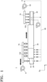
- FIG. 1 illustrates an electrode heat treatment device 1 including an exhaust structure 100
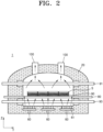
- FIG. 2 illustrates a cross-section of the electrode heat treatment device 1
- FIG. 3 illustrates the exhaust structure 100
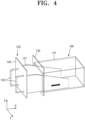
- FIG. 4 illustrates a receiving portion 120 and a supporting portion 130 of the exhaust structure 100
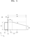
- FIG. 5 illustrates a side of the receiving portion 120
- FIG. 6 illustrates a front of the receiving portion 120
- FIG. 7 illustrates a plane of the receiving portion 120
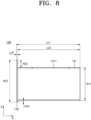
- FIG. 8 illustrates a side of the supporting portion 130
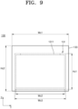
- FIG. 9 illustrates a front of the supporting portion 130
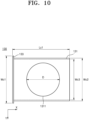
- FIG. 10 illustrates a plane of the supporting portion 130.
- the electrode heat treatment device 1 may change physical properties by heat-treating a material S and may be used to process metals, an alloys, and other materials.
- the electrode heat treatment device 1 may be used to fire the material S that is an anode active material and/or a cathode active material for a secondary battery.
- the material S may be a cathode active material and may be a raw material of a cathode active material of a lithium ion battery, such as LC0(LiCoO 2 ), NCM(Li(Ni, Co, Mn)O 2 ), NCA(Li(Ni, Co, Al)O 2 ), LMO(LiMn 2 O 4 ), LFO(LiFePO 4 ), etc.
- the material S may be received in a case C such as a sagger, etc., and may be transferred by a roller 80 in the electrode heat treatment device 1.
- the electrode heat treatment device 1 which is a roller hearth type heat treatment device, may include a pre-heating zone 10, a heating zone 20, a holding zone 30, a cooling zone 40, exhaust devices 51 and 53, a supply pipe 60, an exhaust pipe 70, the roller 80, heaters 91 and 93, and an exhaust structure 100.
- the pre-heating zone 10 may be located at the front of the electrode heat treatment device 1 and may pre-heat the material S and transfer the material S to the heating zone 20.
- the pre-heating zone 10 may pre-heat the material S to prevent an excessive load from being applied to the heating zone 20.
- the material S is a lithium transition metal compound
- the material S includes a large amount of oxygen and thus moisture may be generated in the material S in a heat treatment process.
- the pre-heating zone 10 may further include a moisture discharge hood (not shown) to smoothly remove and discharge moisture.
- the pre-heating zone 10 may pre-heat the material S to 50 °C to 200 °C, or 70 °C to 150 °C, or 90 °C to 120 °C.
- the pre-heating zone 10 may receive high-temperature gas from the supply pipe 60 and pre-heat the material S. Alternatively, the pre-heating zone 10 may pre-heat the material S through a separate heater.
- the heaters 91 and 93 may heat the material S to 500 °C to 1500 °C, 700 °C to 1400 °C, 800 °C to 1300 °C, 950 °C to 1250 °C, 700 °C to 900 °C, or 300 °C to 400 °C.
- the holding zone 30 may be located at the rear of the heating zone 20 and perform heat treatment by holding the heated material S at a temperature similar to that of the heating zone 20. That is, after the material S is primarily heated in the heating zone 10, the material S is heated to a temperature for heat treatment in the heating zone 20 and then heat-treated while being held at the temperature for heat treatment in the holding zone 30.
- the cooling zone 40 may be located at the rear of the holding zone 30 and cool the material S heat-treated in the holding zone 30.
- the cooling zone 40 may cool the material S by using low-temperature gas.
- the material S passing through the cooling zone 40 may be discharged to outside of the electrode heat treatment device 1.
- the exhaust devices 51 and 53 may discharge the exhaust gas generated in the heat treatment process to outside of the electrode heat treatment device 1.
- the exhaust devices 51 and 53 may be blowing fans or blowing pumps and may be located at the front and the rear of the electrode heat treatment device 1, respectively.
- the exhaust devices 51 and 53 may be connected to the exhaust pipe 70 to discharge exhaust gas introduced from the exhaust structure 100 to the exhaust pipe 70 to outside.
- the supply pipe 60 may be in the electrode heat treatment device 1 and may supply gas to the pre-heating zone 10, the heating zone 20, the holding zone 30, and/or the cooling zone 40. As shown in FIG. 2 , one or more supply pipes 60 may be located under the heating zone 20 and supply gas for heating the material S to the heating zone 20. Alternatively, one or more supply pipes 60 may be located under the pre-heating zone 10 to supply gas for pre-heating the material S, one or more supply pipes 60 may be located under the holding zone 30 to hold the material S at high temperature, or one or more supply pipes 60 may be located under the cooling zone 40 to cool the material S.
- the supply pipe 60 may include a plurality of branch pipes 61.
- the plurality of branch pipes 61 may be branched from each supply pipe 60 to discharge gas toward a bottom of the material S.
- the exhaust pipe 70 may be connected to the plurality of exhaust structures 100 and the exhaust devices 51 and 53.
- the exhaust pipe 70 may be connected to the exhaust structure 100 connected to at least one of the pre-heating zone 10, the heating zone 20, and the holding zone 30.
- the exhaust pipe 70 may be located at each of the front and the rear of the electrode heat treatment device 1, and one exhaust pipe 70 may be connected to the plurality of exhaust structures 100 provided in the pre-heating zone 10, the heating zone 20, and the holding zone 30, and another exhaust pipe 70 may be connected to the plurality of exhaust structures 100 provided in the cooling zone 40.
- the roller 80 may transfer the case C having the material S loaded thereon in the electrode heat treatment device 1.
- a plurality of rollers 80 may be in the heating zone 20 to cross the electrode heat treatment device 1 in a width direction (e.g., a Y-axis direction of FIG. 2 ) and may support and transfer a plurality of cases C. While the heating zone 20 is shown in FIG. 2 , a plurality of rollers 80 may also be in the pre-heating zone 10, the holding zone 30, and the cooling zone 40 as well as the heating zone 20.
- One or more exhaust structures 100 may be at a side of the electrode heat treatment device 1, and may be used to discharge exhaust gas generated in heat treatment of the material S. As shown in FIG. 1 , one or more exhaust structures 100 may be on each of the pre-heating zone 10, the heating zone 20, the holding zone 30, and/or the cooling zone 40. One or more exhaust structures 100 may be in each zone in a length direction (e.g., an X-axis direction of FIG. 1 ) of the electrode heat treatment device 1, and one or more exhaust structures 100 may be in each zone in the width direction (e.g., the Y-axis direction of FIG. 2 ) of the electrode heat treatment device 1.
- a length direction e.g., an X-axis direction of FIG. 1
- the electrode heat treatment device 1 e.g., the Y-axis direction of FIG. 2
- Each exhaust structure 100 may transfer exhaust gas generated in the pre-heating zone 10, the heating zone 20, the holding zone 30, and/or the cooling zone 40 to the exhaust pipe 70, and the exhaust gas may be discharged to outside through the exhaust devices 51 and 53.
- the exhaust structure 100 may also span the entire length direction of the holding zone 30 or may be located at the rear of the holding zone 30.
- the electrode heat treatment device 1 may include one exhaust structure 100 or three or more exhaust structures 100 in the width direction thereof.
- the description will be focused on the exhaust structure 100 in the heating zone 20, but the exhaust structure 100 in the pre-heating zone 10, the holding zone 30, and/or the cooling zone 40 may also have the same configuration as the exhaust structure 100 in the heating zone 20.
- the exhaust structure 100 may include a wall portion 110, a receiving portion 120, and a supporting portion 130.
- the exhaust structure 100 may include the wall portion 110 that defines a first vertical exhaust path 111, a horizontal exhaust path 112, and a second vertical exhaust path 113 that communicate with one another, the supporting portion 130 including a supporting portion body 131 insertable into and removable from the horizontal exhaust path 112, and the receiving portion 120 insertable into and removable from the supporting portion 130, in which the receiving portion 120 may include a receiving portion body 121 that does not directly contact the wall portion 110 by the supporting portion body 131.
- the wall portion 110 may be a lining member that forms an overall shape of the exhaust structure 100 and defines an inner passage through which exhaust gas travels.
- the wall portion 110 may include a material with excellent fire resistance so as not to be easily damaged by high-temperature exhaust gas.
- the material S includes lithium
- a lithium element may penetrate into the wall portion 110 and thus cause the wall portion 110 to crack or peel.
- the wall portion 110 may include a material with excellent resistance to lithium reactivity.
- the wall portion 110 may include a heat-resistant ceramic material such as alumina, mullite, cordierite, silicon carbide, etc.
- the wall portion 110 may include a plurality of fire bricks made of a heat-resistant ceramic material.
- the wall portion 110 may define one or more exhaust paths in which exhaust gas generated in the pre-heating zone 10, the heating zone 20, the holding zone 30, and/or the cooling zone 40 travels.
- the wall portion 110 may define the first vertical exhaust path 111, the horizontal exhaust path 112, and the second vertical exhaust path 113 therein.
- the first vertical exhaust path 111 may extend in the height direction (e.g., the Z-axis direction of FIG. 3 ) and may be connected to the horizontal exhaust path 112.
- the horizontal exhaust path 112 may extend in the horizontal direction (e.g., the X-axis direction of FIG. 3 or the length direction of the exhaust path 1) at a side of the first vertical exhaust path 111 and may have the receiving portion 120 and the supporting portion 130 inserted thereinto. As the exhaust gas introduced from the first vertical exhaust path 111 passes through the horizontal exhaust path 112, particles included in the exhaust gas may sink down. To prevent the sinking particles from blocking the horizontal exhaust path 112, the receiving portion 120 in the horizontal exhaust path 112 may collect the particles.
- the horizontal exhaust path 112 may have a length L.
- the length L of the horizontal exhaust path 112 may be equal to a length of the receiving portion body 121 and a length of the supporting portion body 131 described below.
- the length of the receiving portion body 121 and the length of the supporting portion body 131 may be at least 80 % but not more than 100 % of the length L of the horizontal exhaust path 112.
- the length of the receiving portion body 121 and the length of the supporting portion body 131 are less than 80 % of the length L, the effect of collecting particles may be degraded.
- the length of the receiving portion body 121 and the length of the supporting portion body 131 exceed 100 % of the length L, flow of the exhaust gas may be hindered by the receiving portion body 121 and the supporting portion body 131 that leave the horizontal exhaust path 112.
- the horizontal exhaust path 112 may have a height H1.
- the height H1 may be greater than or equal to a height of the supporting portion 130.
- a top surface and a bottom surface of the horizontal exhaust path 112 may be spaced apart from a top surface and a bottom surface of the supporting portion 130 by a gap C.
- the second vertical exhaust path 113 may extend in the vertical direction (e.g., a Z-axis direction of FIG. 3 or the height direction of the electrode heat treatment device 1) at a side of the horizontal exhaust path 112.
- the second vertical exhaust path 113 may extend from an upper portion of the horizontal exhaust path 112 in the vertical direction.
- the second vertical exhaust path 113 may be connected to the exhaust pipe 70.
- the second vertical exhaust path 113 may include a first exhaust outlet 1131 and a second exhaust outlet 1132.
- the first exhaust outlet 1131 may be under the second vertical exhaust path 113 and may be connected to the horizontal exhaust path 112.
- the first exhaust outlet 1131 may be formed to be circular and may have a diameter D1.
- the diameter D1 may be greater than or equal to a diameter D of a communicating hole 1311 of the supporting portion body 131, such that the exhaust gas may smoothly travel to the first exhaust outlet 1131 through the horizontal exhaust path 112, the receiving portion 120, and the supporting portion 130.
- the second exhaust outlet 1132 may be on the second vertical exhaust path 113 and may be connected to the first exhaust outlet 1131 and the exhaust pipe 70.
- the second exhaust outlet 1132 may be formed to be circular and may have a diameter D2 greater than the diameter D1.
- the second exhaust outlet 1132 may be coaxial with the first exhaust outlet 1131.
- the exhaust gas may be smoothly discharged from the second vertical exhaust path 113 to the exhaust pipe 70.
- the wall portion 110 may further include a buffering zone 114.
- the buffering zone 114 may be a zone formed above the horizontal exhaust path 112 in the height direction of the first vertical exhaust path 111. After a part of the exhaust gas introduced through the first vertical exhaust path 111 is introduced to the buffering zone 114 and is held temporarily, the part of the exhaust gas may be introduced to the horizontal exhaust path 112 at relatively low temperature, low speed, and low pressure.
- the buffering zone 114 may lower temperature, pressure, and flow rate of the exhaust gas to prevent high-temperature exhaust gas from being directly introduced to the horizontal exhaust path 112 and thus damaging the wall portion 110, the receiving portion 120, and the supporting portion 130 corresponding to the horizontal exhaust path 112.
- the wall portion 110 may further include a reinforcing member 115 corresponding to the buffering zone 114.
- the reinforcing member 115 may cover one or more inner sides of the buffering zone 114 and prevent the wall portion 110 corresponding to the buffering zone 114 from being damaged by the high-temperature exhaust gas.
- the reinforcing member 115 may include a material having higher heat resistance and strength than the wall portion 110 in the other zones. While it is shown in FIG. 3 that the reinforcing member 115 is on a top surface of the buffering zone 114, the reinforcing member 115 may be on each side of the buffering zone 114.
- the receiving portion 120 may receive particles included in the exhaust gas being in the horizontal exhaust path 112 and traveling to the second vertical exhaust path 113 through the horizontal exhaust path 112.
- the receiving portion 120 may be inserted into and removed from the supporting portion 130 in the horizontal exhaust path 112.
- the receiving portion 120 may include an alloy material capable of enduring a high-temperature and corrosive environment.
- the receiving portion 120 may include a stainless steel alloy such as SUS310S.
- the receiving portion 120 may include the receiving portion body 121, a receiving portion flange 123, and a handle 125.
- the receiving portion body 121 may directly receive particles included in exhaust gas, etc., and may be located at opposite sides of the receiving portion 120 and may be inserted into the supporting portion 130. As shown in FIG. 4 , the receiving portion body 121 may have an open top surface to communicate with the first vertical exhaust path 111, the horizontal exhaust path 112, and the supporting portion 130. A pair of receiving portion bodies 121 may be spaced apart from each other in a width direction (e.g., the Y-axis direction of FIG. 4 ) of the receiving portion 120 and each may have a length Ld2.
- the length Ld2 may be a length from a rear surface of the receiving portion flange 123 to an end portion of the receiving portion body 121. As described above, the length Ld2 may be at least 80 % but not more than 100 % of the length L of the horizontal exhaust path 112. Ld2 may be equal to a length Lc2 of the supporting portion body 131 described below.
- the receiving portion body 121 may include a horizontal portion 1211 having a flat top and an inclined portion 1213 extending down inclinedly from an end of the horizontal portion 1211, in which the horizontal exhaust path 112 may extend horizontally from a side of the first vertical exhaust path 111, the second vertical exhaust path 113 may extend vertically from a side of the horizontal exhaust path 112, and the supporting portion body 131 may include the communicating hole 1311 open toward the second vertical exhaust path 113.
- the receiving portion body 121 may include the horizontal portion 1211 and the inclined portion 1213.
- the horizontal portion 1211 may extend from the rear surface of the receiving portion flange 123 and a top thereof may extend flat.
- the horizontal portion 1211 may have a length Ld4 and a height Hd1.
- the inclined portion 1213 may extend down inclinedly from the rear end of the horizontal portion 1211.
- the top end of the horizontal portion 1211 may be spaced apart from a top inner side of the supporting portion 130 by a height H4.
- the length Ld4 may be 20 % to 60 % of Ld2. When the length Ld4 is less than 20 % of Ld2, the horizontal portion 1211 may become excessively short and thus an ability of the receiving portion 120 to collect particles may be degraded.
- a rear-end height Hd2 of the inclined portion 1213 may be 50 % to 80 % of Hd1.
- Hd2 When Hd2 is less than 50 % of Hd1, particles loaded on the receiving portion 120, etc., may scatter due to flow of exhaust gas.
- Hd2 exceeds 80 % of Hd1, the rear end of the inclined portion 1213 may serve as a barrier to impede the flow of the exhaust gas and the particles may not be sufficiently received in the receiving portion 120.
- the length of the inclined portion 1213 may be greater than the length Ld4 of the horizontal portion 1211.
- the supporting portion body 131 may have a width Wc2 between inner sides and a width Wc3 between outer sides.
- Wc2 may be greater than or equal to a width of the horizontal exhaust path 112.
- Wc3 may be greater than or equal to the width Wd2 of the receiving portion body 121.
Landscapes
- Engineering & Computer Science (AREA)
- Mechanical Engineering (AREA)
- General Engineering & Computer Science (AREA)
- Environmental & Geological Engineering (AREA)
- Exhaust Gas After Treatment (AREA)
- Physical Or Chemical Processes And Apparatus (AREA)
Applications Claiming Priority (2)
| Application Number | Priority Date | Filing Date | Title |
|---|---|---|---|
| KR1020230089086A KR20250009149A (ko) | 2023-07-10 | 2023-07-10 | 배기 구조체 및 이를 포함하는 전극재 열처리 장치 |
| PCT/KR2024/007608 WO2025014095A1 (ko) | 2023-07-10 | 2024-06-04 | 배기 구조체 및 이를 포함하는 전극재 열처리 장치 |
Publications (2)
| Publication Number | Publication Date |
|---|---|
| EP4521049A1 true EP4521049A1 (de) | 2025-03-12 |
| EP4521049A4 EP4521049A4 (de) | 2026-04-29 |
Family
ID=94210915
Family Applications (1)
| Application Number | Title | Priority Date | Filing Date |
|---|---|---|---|
| EP24751622.2A Pending EP4521049A4 (de) | 2023-07-10 | 2024-06-04 | Abgasstruktur und elektrodenmaterialwärmebehandlungsvorrichtung damit |
Country Status (2)
| Country | Link |
|---|---|
| US (1) | US20250020406A1 (de) |
| EP (1) | EP4521049A4 (de) |
Family Cites Families (5)
| Publication number | Priority date | Publication date | Assignee | Title |
|---|---|---|---|---|
| JP2002295978A (ja) * | 2001-03-29 | 2002-10-09 | Noritake Co Ltd | 焼成炉 |
| KR200324846Y1 (ko) * | 2003-06-10 | 2003-08-27 | 이규일 | 매연 방지형 소각보일러 |
| KR101559051B1 (ko) * | 2013-12-24 | 2015-10-08 | 김연중 | 배기부 구조가 개선된 화목보일러 |
| KR101993209B1 (ko) * | 2018-05-25 | 2019-06-27 | 주식회사 한화 | 이차전지 양극활물질 제조용 열처리로 |
| KR102519322B1 (ko) * | 2021-10-29 | 2023-04-10 | 주식회사 한화 | 분체용 열처리 로의 배기연도 구조체 |
-
2024
- 2024-06-04 EP EP24751622.2A patent/EP4521049A4/de active Pending
- 2024-08-19 US US18/808,687 patent/US20250020406A1/en active Pending
Also Published As
| Publication number | Publication date |
|---|---|
| US20250020406A1 (en) | 2025-01-16 |
| EP4521049A4 (de) | 2026-04-29 |
Similar Documents
| Publication | Publication Date | Title |
|---|---|---|
| US20140069234A1 (en) | Valuable metal recovery method | |
| KR20010007296A (ko) | 직접적인 제련 용기 | |
| JP7377760B2 (ja) | 連続焼成炉および粉体材料の連続焼成方法 | |
| CN110770359A (zh) | 金属铸块的制造方法 | |
| CN103270197A (zh) | 用于从电解氧化物还原系统捕集和去除废气的阳极护罩 | |
| JP2019175546A (ja) | 熔融分離装置、廃リチウムイオン電池からのアルミニウムの分離方法、及び廃リチウムイオン電池からの有価物の回収方法 | |
| US20250020406A1 (en) | Exhaust structure and electrode heat treatment device comprising the same | |
| KR102899074B1 (ko) | 전극재 소성장치 | |
| KR20250009149A (ko) | 배기 구조체 및 이를 포함하는 전극재 열처리 장치 | |
| KR20130004669U (ko) | 조립형 흑연 관 및 그로써 구성된 흑연 도가니 | |
| JP7319219B2 (ja) | 連続焼成炉 | |
| JP2000203947A (ja) | リチウム複合金属酸化物の焼成装置およびその焼成方法 | |
| JP7301016B2 (ja) | 連続焼成炉 | |
| KR102792666B1 (ko) | 열처리 장치용 새거 정렬 구조체 | |
| CN201459211U (zh) | 真空冶炼还原罐料筒 | |
| CN210004775U (zh) | 匣钵 | |
| KR20210152897A (ko) | 전극재 소성장치 | |
| JP3758432B2 (ja) | 真空精錬装置の地金付着防止方法および真空精錬装置の排気ダクト | |
| CN221795301U (zh) | 一种粉末高温合金领域钢液防穿透托盘 | |
| CN220829074U (zh) | 连续式烧成炉 | |
| TWI859385B (zh) | 成形裝置、具備如該成形裝置之製造設備、及玻璃板之製造方法 | |
| JP6221477B2 (ja) | 銅製錬用ps型転炉の炉口 | |
| CN211120638U (zh) | 一种硬质合金烧结炉用产品石墨托板 | |
| CN208635556U (zh) | 富氧负压熔炼炉 | |
| JPH07268430A (ja) | 溶銑予備処理用浸漬単管ランス |
Legal Events
| Date | Code | Title | Description |
|---|---|---|---|
| STAA | Information on the status of an ep patent application or granted ep patent |
Free format text: STATUS: UNKNOWN |
|
| STAA | Information on the status of an ep patent application or granted ep patent |
Free format text: STATUS: THE INTERNATIONAL PUBLICATION HAS BEEN MADE |
|
| PUAI | Public reference made under article 153(3) epc to a published international application that has entered the european phase |
Free format text: ORIGINAL CODE: 0009012 |
|
| STAA | Information on the status of an ep patent application or granted ep patent |
Free format text: STATUS: REQUEST FOR EXAMINATION WAS MADE |
|
| 17P | Request for examination filed |
Effective date: 20240814 |
|
| AK | Designated contracting states |
Kind code of ref document: A1 Designated state(s): AL AT BE BG CH CY CZ DE DK EE ES FI FR GB GR HR HU IE IS IT LI LT LU LV MC ME MK MT NL NO PL PT RO RS SE SI SK SM TR |
|
| A4 | Supplementary search report drawn up and despatched |
Effective date: 20260330 |
|
| RIC1 | Information provided on ipc code assigned before grant |
Ipc: F27B 3/22 20060101AFI20260324BHEP Ipc: F27D 7/04 20060101ALI20260324BHEP Ipc: F27D 3/00 20060101ALI20260324BHEP Ipc: F23G 5/44 20060101ALI20260324BHEP Ipc: F23J 11/00 20060101ALI20260324BHEP Ipc: F23J 13/08 20060101ALI20260324BHEP Ipc: F27B 9/30 20060101ALI20260324BHEP Ipc: F27D 17/20 20250101ALI20260324BHEP Ipc: F27D 17/22 20250101ALI20260324BHEP Ipc: F27D 17/30 20250101ALI20260324BHEP |