EP4520900A1 - Self-adjusting vehicle door lock catch assembly and mounting method therefor, and vehicle - Google Patents
Self-adjusting vehicle door lock catch assembly and mounting method therefor, and vehicle Download PDFInfo
- Publication number
- EP4520900A1 EP4520900A1 EP23818963.3A EP23818963A EP4520900A1 EP 4520900 A1 EP4520900 A1 EP 4520900A1 EP 23818963 A EP23818963 A EP 23818963A EP 4520900 A1 EP4520900 A1 EP 4520900A1
- Authority
- EP
- European Patent Office
- Prior art keywords
- lock catch
- base
- vehicle door
- self
- door lock
- Prior art date
- Legal status (The legal status is an assumption and is not a legal conclusion. Google has not performed a legal analysis and makes no representation as to the accuracy of the status listed.)
- Granted
Links
Images

Classifications
-
- E—FIXED CONSTRUCTIONS
- E05—LOCKS; KEYS; WINDOW OR DOOR FITTINGS; SAFES
- E05B—LOCKS; ACCESSORIES THEREFOR; HANDCUFFS
- E05B85/00—Details of vehicle locks not provided for in groups E05B77/00 - E05B83/00
- E05B85/04—Strikers
-
- E—FIXED CONSTRUCTIONS
- E05—LOCKS; KEYS; WINDOW OR DOOR FITTINGS; SAFES
- E05B—LOCKS; ACCESSORIES THEREFOR; HANDCUFFS
- E05B85/00—Details of vehicle locks not provided for in groups E05B77/00 - E05B83/00
- E05B85/04—Strikers
- E05B85/045—Strikers for bifurcated bolts
-
- E—FIXED CONSTRUCTIONS
- E05—LOCKS; KEYS; WINDOW OR DOOR FITTINGS; SAFES
- E05B—LOCKS; ACCESSORIES THEREFOR; HANDCUFFS
- E05B79/00—Mounting or connecting vehicle locks or parts thereof
- E05B79/02—Mounting of vehicle locks or parts thereof
-
- E—FIXED CONSTRUCTIONS
- E05—LOCKS; KEYS; WINDOW OR DOOR FITTINGS; SAFES
- E05B—LOCKS; ACCESSORIES THEREFOR; HANDCUFFS
- E05B79/00—Mounting or connecting vehicle locks or parts thereof
- E05B79/02—Mounting of vehicle locks or parts thereof
- E05B79/08—Mounting of individual lock elements in the lock, e.g. levers
-
- E—FIXED CONSTRUCTIONS
- E05—LOCKS; KEYS; WINDOW OR DOOR FITTINGS; SAFES
- E05B—LOCKS; ACCESSORIES THEREFOR; HANDCUFFS
- E05B15/00—Other details of locks; Parts for engagement by bolts of fastening devices
- E05B15/02—Striking-plates; Keepers; Bolt staples; Escutcheons
- E05B15/0205—Striking-plates, keepers, staples
- E05B15/024—Striking-plates, keepers, staples adjustable
- E05B2015/027—Striking-plates, keepers, staples adjustable auto-adjustable
-
- E—FIXED CONSTRUCTIONS
- E05—LOCKS; KEYS; WINDOW OR DOOR FITTINGS; SAFES
- E05B—LOCKS; ACCESSORIES THEREFOR; HANDCUFFS
- E05B15/00—Other details of locks; Parts for engagement by bolts of fastening devices
- E05B15/02—Striking-plates; Keepers; Bolt staples; Escutcheons
- E05B15/0205—Striking-plates, keepers, staples
- E05B15/024—Striking-plates, keepers, staples adjustable
- E05B2015/0275—Striking-plates, keepers, staples adjustable in two directions
Definitions
- the present application relates to the field of interior and exterior trim of a vehicle body, and in particular to a self-adjusting vehicle door lock catch assembly and mounting method therefor, and a vehicle.
- a mid-high frequency range of the sound when the vehicle door is closed is an impact sound between a door lock and a lock cylinder, quality of which greatly affects users' subjective feelings.
- a key factor is an actual relative position between the door lock and the lock cylinder, where adjustment of a vehicle door lock catch is very important. If the adjustment of the vehicle door lock catch is not proper, quality of opening and closing of the vehicle door will be directly affected.
- the self-adjusting door lock catch assembly further includes an exterior trim panel covering the first surface of the base.
- the present application further provides a vehicle including the self-adjusting vehicle door lock catch assembly as described above.
Landscapes
- Lock And Its Accessories (AREA)
- Power-Operated Mechanisms For Wings (AREA)
Abstract
Description
- The present application relates to the field of interior and exterior trim of a vehicle body, and in particular to a self-adjusting vehicle door lock catch assembly and mounting method therefor, and a vehicle.
- With continuous development of an automotive industry, people's requirements for riding comfort of vehicles are becoming more and more stringent, especially quality of a sound when a vehicle door is closed. A mid-high frequency range of the sound when the vehicle door is closed is an impact sound between a door lock and a lock cylinder, quality of which greatly affects users' subjective feelings. A key factor is an actual relative position between the door lock and the lock cylinder, where adjustment of a vehicle door lock catch is very important. If the adjustment of the vehicle door lock catch is not proper, quality of opening and closing of the vehicle door will be directly affected.
- The present application provides a self-adjusting vehicle door lock catch assembly including:
- a lock catch body, including a base and a lock cylinder, where the base is provided with a bolt through-hole, and the base includes a first surface and a second surface opposite each other, the first surface facing a vehicle door and the first surface being provided with a slide groove; and the lock cylinder is fixedly connected to the first surface of the base;
- a floating adjustment piece, provided in the slide groove and configured to adjust a position of the lock catch body, where the floating adjustment piece is provided with an opening, a diameter of the bolt through-hole being greater than a diameter of the opening of the floating adjustment piece;
- a fastener, configured to secure the base to a sheet metal member of a vehicle sidewall, where the diameter of the opening of the floating adjustment piece matches a size of the fastener; and
- a limit block, connected to the base, where a limit groove is provided between the limit block and the base, and the limit block is configured to limit the lock catch body through the limit groove.
- Optionally, there are two slide grooves and two bolt through-holes provided in the first surface of the base, where each of the slide grooves is concentrically arranged with a respective bolt through-hole, with a sliding space reserved in the slide groove for the floating adjustment piece.
- Optionally, the sliding space includes:
- a transverse sliding space, in which the floating adjustment piece adjusts a position of the lock catch body in a Y direction, the Y direction being in line with a width direction of a vehicle body; and
- a longitudinal sliding space, in which the floating adjustment piece adjusts a position of the lock catch body in a Z direction, the Z direction being in line with a height direction of the vehicle body.
- Optionally, the fastener includes a countersunk bolt.
- Optionally, the self-adjusting door lock catch assembly further includes a bushing, provided in an inner wall of the bolt through-hole.
- Optionally, a spacer is provided between the second surface of the base and the sheet metal member of the vehicle sidewall.
- Optionally, the self-adjusting door lock catch assembly further includes at least one base bracket for supporting the base in the Z-direction.
- Optionally, the self-adjusting door lock catch assembly further includes an exterior trim panel covering the first surface of the base.
- In another aspect, the present application further provides a mounting method for the self-adjusting vehicle door lock catch assembly, including:
- pre-tightening and securing the fastener, which passes through the floating adjustment piece and the bolt through-hole, to the sheet metal member of the vehicle sidewall with a first torque;
- upon closing a vehicle door at a preset closing speed until a door lock is in a locked state, self-adaptively adjust the limit block, the floating adjustment piece, and the fastener, such that the lock catch body is matched with the vehicle door;
- tightening the fastener with a second torque, the second torque being greater than the first torque; and
- removing the limit block and installing the exterior trim panel.
- In another aspect, the present application further provides a vehicle including the self-adjusting vehicle door lock catch assembly as described above.
- The self-adjusting vehicle door lock catch assembly according to the present application, is designed with the floating adjustment piece and the limit block, which can automatically calibrate the relative position between the lock catch body and the vehicle door according to an actual position of the vehicle door after the vehicle door is closed, such that the vehicle door and the lock catch body are self-adaptively adjusted to a reasonable state in an up and down direction (Z direction) and a left and right direction (Y direction). The lock catch assembly has strong self-adaptive ability, and relatively wide adjustment range, without excessive auxiliary adjustment structures and equipment, which can not only greatly improve the quality of vehicle door closing, but also save labor costs and time costs, ensure product consistency, and improve production efficiency.
- Other features and advantages of this application will be described in detail in the subsequent DETAILED DESCRIPTION section.
- In order to more clearly illustrate the embodiments of the present application, the accompanying drawings to be used in the description of the embodiments will be briefly described below. It will be apparent that the accompanying drawings in the following description only illustrate some of the embodiments of the present application, where the same reference numerals generally represent the same components. For a person of ordinary skill in the art, other drawings can be obtained from these drawings without any creative labor.
-
FIG. 1 shows a schematic structural diagram of a vehicle door lock catch in the related art. -
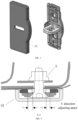
FIG. 2 shows a schematic structural diagram of a self-adjusting vehicle door lock catch assembly according to an embodiment of the present application. -
FIG. 3 shows a schematic structural diagram of an exterior trim panel and a lock catch body of a self-adjusting vehicle door lock catch assembly according to an embodiment of the present application. -
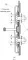
FIG. 4 shows a detailed diagram of an A-A section of a self-adjusting vehicle door lock catch assembly according to an embodiment of the present application. -
FIG. 5 shows a detailed diagram of a B-B section of a self-adjusting vehicle door lock catch assembly according to an embodiment of the present application. -
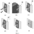
FIG. 6 shows a schematic diagram of a mounting method for a self-adjusting vehicle door lock catch assembly according to an embodiment of the present application. - Additional description of the accompanying drawings is provided below:
1-base; 2-lock cylinder; 3-bolt through-hole; 4-floating adjustment piece; 5-fastener; 6-limit block; 7-bushing; 8-spacer; 9-base bracket; 10-exterior trim panel. - Embodiments of the present application will be clearly and completely described below in conjunction with the accompanying drawings in the embodiments of the present application. It is apparent that the described embodiments are only a part of the embodiments of the present application, and not all of the embodiments. Based on the embodiments in this application, all other embodiments obtained by a person of ordinary skill in the art without making any creative labor fall within the scope of protection of this application.
- "An embodiment" or "embodiments" referred to herein indicates a particular feature, structure, or characteristic that may be included in at least one embodiment of the present application. In the description of the present application, it is to be understood that terms "upper", "lower", "top", "bottom", etc., indicate an orientation or positional relationship based on that shown in the accompanying drawings. These terms are intended only to facilitate and simplify the description of the present application, but not indicate or imply that the device or element referred to must have a particular orientation, be constructed and operated in a particular orientation, and therefore are not to be construed as a limitation of the present application. Furthermore, terms "first" and "second" are used only for descriptive purposes, and are not to be construed as indicating or implying relative importance or implicitly specifying the number of technical features indicated. Thus, a feature defined with the terms "first" and "second" may explicitly or implicitly include one or more such feature. Furthermore, the terms "first", "second", etc. are used to distinguish between similar objects and need not be used to describe a particular order or sequence. It should be understood that the terms so used are interchangeable, where appropriate, so that the embodiments of the present application described herein can be implemented in an order other than those illustrated or described herein.
- For adjustment of an existing vehicle door lock catch, one person on a left side and another person on a right side of vehicles on a production line are required to make fine adjustments to a door of each vehicle coming off the production line. Due to a limited range of the adjustment, and because of requirements of the production takt, it is difficult to ensure that mass-produced vehicles on the entire production line are adjusted to a desired quality of sound when the door is closed.
- Referring to
FIG. 1, FIG. 1 shows a schematic structural diagram of a vehicle door lock catch in the related art. The vehicle door lock catch in the related art generally includes abase 1, alock cylinder 2, and aspacer 8, and is fixed to a sidewall pillar by two countersunk bolts. During installation, it is necessary to manually check whether a relative position between the lock cylinder and the vehicle door is appropriate. - Referring to
FIG. 2 andFIG. 3 , embodiments of the present application provide a self-adjusting vehicle door lock catch assembly, including: - a lock catch body, including a
base 1 and alock cylinder 2, where thebase 1 is provided with a bolt through-hole 3, and thebase 1 includes a first surface and a second surface opposite each other, the first surface facing a vehicle door and the first surface being provided with a slide groove; and thelock cylinder 2 is fixedly connected to the first surface of thebase 1; - a
floating adjustment piece 4, provided in the slide groove and configured to adjust a position of the lock catch body, where the floatingadjustment piece 4 is provided with an opening, a diameter of the bolt through-hole 3 being greater than a diameter of the opening of the floatingadjustment piece 4; - a
fastener 5, configured to secure thebase 1 to a sheet metal member of a vehicle sidewall, where the diameter of the opening of thefloating adjustment piece 4 matches a size of thefastener 5; and - a
limit block 6, connected to thebase 1, where a limit groove is provided between thelimit block 6 and thebase 1, and thelimit block 6 is configured to limit the lock catch body through the limit groove. - Material of the
base 1 in the embodiment of the present application may include polyoxymethylene (POM). Thelock cylinder 2 is provided in the middle of the first surface of thebase 1, and faces the vehicle door. In a possible embodiment, two bolt through-holes 3 are provided in thebase 1 above and below thelock cylinder 2 in a height direction of a vehicle body, with thelock cylinder 2 as a centerline. Thefastener 5 passes through the corresponding bolt through-hole 3 to secure thebase 1 to the sheet metal member of the vehicle sidewall. In a possible embodiment, thefastener 5 includes a countersunk bolt. Thefastener 5 further includes a nut matching the countersunk bolt, which can be mounted, for example, on a nut plate on an inner side of an inner panel of the sidewall. - During installation of the lock catch assembly, the
fastener 5, which passes through the floatingadjustment piece 4 and the bolt through-hole 3, is pre-tightened and secured to the sheet metal member of the vehicle sidewall with a first torque. The vehicle door is then closed at a preset closing speed until the door lock is in a locked state. At this time, thelimit block 6, the floatingadjustment piece 4, and thefastener 5 are self-adaptively adjusted so that the lock catch body is matched with the vehicle door, i.e., thelimit block 6, the floatingadjustment piece 4, and thefastener 5 are self-adaptively adjusted to a desired position. Thefastener 5 is then tightened with a second torque greater than the first torque, and thelimit block 6 is removed. In the embodiment of the present application, material of thelimit block 6 may include polyamide 66 (PA66). - In a possible embodiment, the first surface of the
base 1 is provided with two slide grooves, each of which is concentrically arranged with a respective bolt through-hole 3, and has a sliding space reserved for sliding of the floatingadjustment piece 4. The floatingadjustment piece 4 is mounted in the corresponding slide groove, a size of the slide groove being larger than a size of the floatingadjustment piece 4, to leave space for the floatingadjustment piece 4 to slide, so that the floatingadjustment piece 4 can be moved up and down, and left and right. - In a possible embodiment, the sliding space includes: a transverse sliding space, in which the floating
adjustment piece 4 adjusts a position of the lock catch body in a Y direction, the Y direction being in line with a width direction of the vehicle body, with reference to details of the A-A section shown inFIG. 4 ; and a longitudinal sliding space, in which the floatingadjustment piece 4 adjusts a position of the lock catch body in a Z direction, the Z direction being in line with a height direction of the vehicle body, with reference to details of the B-B section shown inFIG. 5 . - In a possible embodiment, the self-adjusting vehicle door lock catch assembly further includes a
bushing 7, provided on an inner wall of the bolt through-hole 3. In particular, thebushing 7 acts as a seal. During installation of the lock catch assembly, the floatingadjustment piece 4 is required to adjust the position of the lock catch body. Thefastener 5 passes through the floatingadjustment piece 4 and the bolt through-hole 3 to fix the lock catch body, where the diameter of the bolt through-hole 3 is larger than the diameter of the opening of the floatingadjustment piece 4. When the floatingadjustment piece 4 is adaptively adjusted to an appropriate position, thefastener 5 is tightened, and at this time, thebushing 7 cooperates with the space where the floatingadjustment piece 4 moves, so that thefastener 5 is fastened to the bolt through-hole 3. - In a possible embodiment, a
spacer 8 is provided between the second surface of thebase 1 and the sheet metal member of the vehicle sidewall. In a possible embodiment, the self-adjusting vehicle door lock catch assembly further includes at least onebase bracket 9 for supporting thebase 1 in the Z direction. In the embodiment of the present application, there are twobase brackets 9, which are provided at upper and lower ends of thebase 1 in the height direction of the vehicle body, so as to secure and support thebase 1. Material of thebase bracket 9 may include POM. - In a possible embodiment, the self-adjusting vehicle door lock catch assembly further includes an
exterior trim panel 10, covering the first surface of thebase 1. After thefastener 5 is tightened and thelimit block 6 is removed, theexterior trim panel 10 is installed to make the lock catch assembly more aesthetically pleasing. - In another aspect, referring to
FIG. 6 , embodiments of the present application further provide a mounting method for the self-adjusting vehicle door lock catch assembly including: - pre-tightening and securing the
fastener 5, which passes through the floatingadjustment piece 4 and the bolt through-hole 3, to the sheet metal member of the vehicle sidewall with a first torque, as shown in (a) inFIG. 6 ; - upon closing the vehicle door at a preset closing speed until a door lock is in a locked state, self-adaptively adjusting the
limit block 6, the floatingadjustment piece 4, and thefastener 5, such that the lock catch body is matched with the vehicle door, as shown in (b) inFIG. 6 ; - tightening the
fastener 5 with a second torque, the second torque being greater than the first torque, as shown in (c) inFIG. 6 ; and - removing the
limit block 6 and installing theexterior trim panel 10, as shown in (d), (e) and (f) inFIG. 6 . - In another aspect, embodiments of the present application further provide a vehicle including the self-adjusting vehicle door lock catch assembly as described above.
- With the self-adjusting vehicle door lock catch assembly and the mounting method therefor, and the vehicle according to the embodiments of the present application, the limit block, the floating adjustment piece, and the fastener automatically calibrate the relative position between the lock catch body and the vehicle door according to an actual position of the vehicle door after the vehicle door is closed, such that the vehicle door and the lock catch body are self-adaptively adjusted to a reasonable state in an up and down direction (Z direction) and a left and right direction (Y direction). The lock catch assembly has strong self-adaptive ability, and relatively wide adjustment range, without excessive auxiliary adjustment structures and equipment, which can not only greatly improve the quality of vehicle door closing, but also save labor costs and time costs, ensure product consistency, and improve production efficiency.
- The foregoing are only some embodiments of the present application, and are not intended to limit the present application, and any modifications, equivalent substitutions, improvements, etc. made within the spirit and principles of the present application shall be included in the scope of protection of the present application.
Claims (10)
- A self-adjusting vehicle door lock catch assembly, comprising:a lock catch body, comprising a base (1) and a lock cylinder (2), wherein the base (1) is provided with a bolt through-hole (3), and the base (1) comprises a first surface and a second surface opposite each other, the first surface facing a vehicle door and the first surface being provided with a slide groove; and the lock cylinder (2) is fixedly connected to the first surface of the base (1);a floating adjustment piece (4), provided in the slide groove and configured to adjust a position of the lock catch body, wherein the floating adjustment piece (4) is provided with an opening, a diameter of the bolt through-hole (3) being greater than a diameter of the opening of the floating adjustment piece (4);a fastener (5), configured to secure the base (1) to a sheet metal member of a vehicle sidewall, wherein the diameter of the opening of the floating adjustment piece (4) matches a size of the fastener (5); anda limit block (6), connected to the base (1), wherein a limit groove is provided between the limit block (6) and the base (1), and the limit block (6) is configured to limit the lock catch body through the limit groove.
- The self-adjusting vehicle door lock catch assembly according to claim 1, wherein there are two slide grooves and two bolt through-holes (3) provided in the first surface of the base (1), wherein each of the slide grooves is concentrically arranged with a respective bolt through-hole (3), with a sliding space reserved in the slide groove for the floating adjustment piece (4).
- The self-adjusting vehicle door lock catch assembly according to claim 2, wherein the sliding space comprises:a transverse sliding space, in which the floating adjustment piece (4) adjusts a position of the lock catch body in a Y direction, the Y direction being in line with a width direction of a vehicle body; anda longitudinal sliding space, in which the floating adjustment piece (4) adjusts a position of the lock catch body in a Z direction, the Z direction being in line with a height direction of the vehicle body.
- The self-adjusting vehicle door lock catch assembly according to any one of claims 1-3, wherein the fastener (5) comprises a countersunk bolt.
- The self-adjusting vehicle door lock catch assembly according to any one of claims 1-4, further comprising a bushing (7), provided on an inner wall of the bolt through-hole (3).
- The self-adjusting vehicle door lock catch assembly according to any one of claims 1-5, wherein a spacer (8) is provided between the second surface of the base (1) and the sheet metal member of the vehicle sidewall.
- The self-adjusting vehicle door lock catch assembly according to claim 3, further comprising at least one base bracket (9) for supporting the base (1) in the Z direction.
- The self-adjusting vehicle door lock catch assembly according to any one of claims 1-7, further comprising an exterior trim panel (10) covering the first surface of the base (1).
- A mounting method for the self-adjusting vehicle door lock catch assembly according to any one of claims 1-8, comprising:pre-tightening and securing the fastener (5), which passes through the floating adjustment piece (4) and the bolt through-hole (3), to the sheet metal member of the vehicle sidewall with a first torque;upon closing the vehicle door at a preset closing speed until a door lock is in a locked state, self-adaptively adjusting the limit block (6), the floating adjustment piece (4), and the fastener (5), such that the lock catch body is matched with the vehicle door;tightening the fastener (5) with a second torque, the second torque being greater than the first torque; andremoving the limit block (6) and installing an exterior trim panel (10).
- A vehicle, comprising the self-adjusting vehicle door lock catch assembly according to any one of claims 1-8.
Applications Claiming Priority (2)
| Application Number | Priority Date | Filing Date | Title |
|---|---|---|---|
| CN202210639465.6A CN115182654B (en) | 2022-06-07 | 2022-06-07 | Self-adjusting door latch assembly and installation method thereof and vehicle |
| PCT/CN2023/096794 WO2023236798A1 (en) | 2022-06-07 | 2023-05-29 | Self-adjusting vehicle door lock catch assembly and mounting method therefor, and vehicle |
Publications (3)
| Publication Number | Publication Date |
|---|---|
| EP4520900A1 true EP4520900A1 (en) | 2025-03-12 |
| EP4520900A4 EP4520900A4 (en) | 2025-08-13 |
| EP4520900B1 EP4520900B1 (en) | 2026-04-29 |
Family
ID=83514238
Family Applications (1)
| Application Number | Title | Priority Date | Filing Date |
|---|---|---|---|
| EP23818963.3A Active EP4520900B1 (en) | 2022-06-07 | 2023-05-29 | Self-adjusting vehicle door lock catch assembly and mounting method therefor, and vehicle |
Country Status (8)
| Country | Link |
|---|---|
| US (1) | US20250101777A1 (en) |
| EP (1) | EP4520900B1 (en) |
| JP (1) | JP2025521217A (en) |
| KR (1) | KR20250011701A (en) |
| CN (1) | CN115182654B (en) |
| AU (1) | AU2023283886B2 (en) |
| CA (1) | CA3258502A1 (en) |
| WO (1) | WO2023236798A1 (en) |
Families Citing this family (2)
| Publication number | Priority date | Publication date | Assignee | Title |
|---|---|---|---|---|
| CN115182654B (en) * | 2022-06-07 | 2025-04-29 | 浙江极氪智能科技有限公司 | Self-adjusting door latch assembly and installation method thereof and vehicle |
| CN115898203B (en) * | 2022-11-15 | 2025-11-07 | 江苏徐工国重实验室科技有限公司 | Side door system assembly and engineering vehicle |
Family Cites Families (22)
| Publication number | Priority date | Publication date | Assignee | Title |
|---|---|---|---|---|
| US6715808B2 (en) * | 2000-02-22 | 2004-04-06 | Atoma International Corp. | Power striker mechanism with backdrive prevention |
| US6666487B2 (en) * | 2000-02-25 | 2003-12-23 | Atoma International Corp. | Power striker with toggle linkage drive mechanism |
| FR2917443B1 (en) * | 2007-06-15 | 2012-10-12 | Peugeot Citroen Automobiles Sa | APPARATUS FOR PREPOSITIONING A SPACER FOR COOPERATING WITH A LOCK OF AN OPENING OF A MOTOR VEHICLE AND MOTOR VEHICLE COMPRISING AT LEAST ONE SUCH DEVICE |
| US9297183B2 (en) * | 2010-03-01 | 2016-03-29 | Daws Manufacturing Company, Inc. | Self-adjusting striker assembly |
| JP5633313B2 (en) * | 2010-11-04 | 2014-12-03 | アイシン精機株式会社 | Vehicle door fixing device, movable wedge device thereof, and method of assembling the same |
| JP5915025B2 (en) * | 2010-12-27 | 2016-05-11 | アイシン精機株式会社 | Vehicle door fixing device and vehicle door movable wedge device |
| EP2708683B1 (en) * | 2012-09-12 | 2015-05-20 | Fiat Group Automobiles S.p.A. | Striker device for a motor vehicle door lock and a motor vehicle equipped with such striker device |
| CN203201253U (en) * | 2013-04-03 | 2013-09-18 | 北京汽车股份有限公司 | Door lock bolt nut plate assembly and automobile |
| CN203361789U (en) * | 2013-06-14 | 2013-12-25 | 北汽福田汽车股份有限公司 | Vehicle door lock catch installation regulating device |
| CN206522030U (en) * | 2017-02-28 | 2017-09-26 | 东风小康汽车有限公司重庆分公司 | Automobile latches installation structure assembly |
| DE202018106887U1 (en) * | 2018-12-04 | 2019-01-23 | Sphinx Electronics Gmbh & Co. Kg | Self-adjusting striker for one clamping unit |
| CN210948108U (en) * | 2019-07-26 | 2020-07-07 | 奇瑞商用车(安徽)有限公司 | Car door lock catch mounting structure |
| CN212054191U (en) * | 2019-10-28 | 2020-12-01 | 江苏吉麦新能源车业有限公司 | Fixing device of car door lock catch |
| DE102021101888A1 (en) * | 2020-02-06 | 2021-08-12 | Magna BÖCO GmbH | LOCKER ARRANGEMENT FOR LOCKING IN MOTOR VEHICLES |
| CN212716254U (en) * | 2020-04-10 | 2021-03-16 | 摩登汽车(盐城)有限公司 | Stopper mounting bracket and vehicle door stopper assembly containing the same |
| CN111894369B (en) * | 2020-06-19 | 2021-12-21 | 浙江吉利汽车研究院有限公司 | Self-adjusting vehicle door lock catch and vehicle with same |
| CN213838129U (en) * | 2020-08-28 | 2021-07-30 | 奇瑞汽车股份有限公司 | Hair cover locking structure and automobile |
| CN214196913U (en) * | 2020-12-14 | 2021-09-14 | 恒大新能源汽车投资控股集团有限公司 | Car door lock catch nut plate and vehicle |
| CN214463376U (en) * | 2020-12-21 | 2021-10-22 | 上海机动车检测中心技术有限公司 | Unlocking device for handle in side door of passenger car |
| DE202021102083U1 (en) * | 2021-04-19 | 2021-05-04 | Sphinx Electronics Gmbh & Co Kg | Self-adjusting striker for a locking unit |
| EP4219872A1 (en) * | 2022-01-27 | 2023-08-02 | Minebea AccessSolutions France | Adjustable striker for a vehicle and method for adjusting the adjustable striker |
| CN115182654B (en) * | 2022-06-07 | 2025-04-29 | 浙江极氪智能科技有限公司 | Self-adjusting door latch assembly and installation method thereof and vehicle |
-
2022
- 2022-06-07 CN CN202210639465.6A patent/CN115182654B/en active Active
-
2023
- 2023-05-29 CA CA3258502A patent/CA3258502A1/en active Pending
- 2023-05-29 KR KR1020247043284A patent/KR20250011701A/en active Pending
- 2023-05-29 EP EP23818963.3A patent/EP4520900B1/en active Active
- 2023-05-29 JP JP2024572266A patent/JP2025521217A/en active Pending
- 2023-05-29 AU AU2023283886A patent/AU2023283886B2/en active Active
- 2023-05-29 WO PCT/CN2023/096794 patent/WO2023236798A1/en not_active Ceased
-
2024
- 2024-12-06 US US18/971,011 patent/US20250101777A1/en active Pending
Also Published As
| Publication number | Publication date |
|---|---|
| US20250101777A1 (en) | 2025-03-27 |
| KR20250011701A (en) | 2025-01-21 |
| CN115182654B (en) | 2025-04-29 |
| EP4520900B1 (en) | 2026-04-29 |
| WO2023236798A1 (en) | 2023-12-14 |
| AU2023283886A1 (en) | 2025-01-09 |
| EP4520900A4 (en) | 2025-08-13 |
| AU2023283886B2 (en) | 2026-02-12 |
| CN115182654A (en) | 2022-10-14 |
| CA3258502A1 (en) | 2025-04-07 |
| JP2025521217A (en) | 2025-07-08 |
Similar Documents
| Publication | Publication Date | Title |
|---|---|---|
| US20250101777A1 (en) | Self-adjusting vehicle door lock catch assembly and mounting method therefor, and vehicle | |
| US8322762B2 (en) | Door gap adjustment for a motor vehicle | |
| US5074609A (en) | Adjustable deck lid hinge pivot | |
| US8763308B2 (en) | Structural door module | |
| US9675215B2 (en) | Shower door assembly | |
| US6729073B2 (en) | Connector for attaching a window panel to a drive element of window-lift device | |
| US7766402B2 (en) | Bumper mounting system | |
| CN216833948U (en) | Structure for quickly installing electric tail wing of automobile trunk | |
| US20220402432A1 (en) | Structure and method for mounting flag-type side mirror | |
| US4535503A (en) | Door glass hinge having a spacer ring | |
| WO2004020247A2 (en) | Automobile hinges | |
| US20080148647A1 (en) | Adjustable Mounting Assembly | |
| US6148564A (en) | Vehicle door module | |
| CN207485168U (en) | A kind of adjustable automobile latch for vehicle door mounting structure | |
| US6564525B1 (en) | Roll formed hardware module | |
| CN111251225B (en) | Y-direction size assembling and positioning tool for car body tail door | |
| CN212002827U (en) | Door frame structure capable of adjusting width and height | |
| CN114135178B (en) | Adjustable column type hinge for door and window | |
| KR100388172B1 (en) | Nothing control install structure of Door striker | |
| CA2576651C (en) | Bumper mounting system | |
| CN118478967A (en) | White car body side sliding door adjusting method | |
| CN114834367A (en) | Outer decorative frame of door window, no step plane formula closing device and car | |
| GB2117442A (en) | Improvements in or relating to a corner bearing for turn-tilt members of windows doors or the like | |
| KR19980034999U (en) | Door-side hinge mounting structure of automobile door | |
| JPH04186902A (en) | Vehicle antenna fitting device |
Legal Events
| Date | Code | Title | Description |
|---|---|---|---|
| STAA | Information on the status of an ep patent application or granted ep patent |
Free format text: STATUS: THE INTERNATIONAL PUBLICATION HAS BEEN MADE |
|
| PUAI | Public reference made under article 153(3) epc to a published international application that has entered the european phase |
Free format text: ORIGINAL CODE: 0009012 |
|
| STAA | Information on the status of an ep patent application or granted ep patent |
Free format text: STATUS: REQUEST FOR EXAMINATION WAS MADE |
|
| 17P | Request for examination filed |
Effective date: 20241205 |
|
| AK | Designated contracting states |
Kind code of ref document: A1 Designated state(s): AL AT BE BG CH CY CZ DE DK EE ES FI FR GB GR HR HU IE IS IT LI LT LU LV MC ME MK MT NL NO PL PT RO RS SE SI SK SM TR |
|
| A4 | Supplementary search report drawn up and despatched |
Effective date: 20250714 |
|
| RIC1 | Information provided on ipc code assigned before grant |
Ipc: E05B 85/04 20140101AFI20250708BHEP Ipc: E05B 79/02 20140101ALI20250708BHEP Ipc: E05B 65/00 20060101ALI20250708BHEP |
|
| DAV | Request for validation of the european patent (deleted) | ||
| DAX | Request for extension of the european patent (deleted) | ||
| GRAP | Despatch of communication of intention to grant a patent |
Free format text: ORIGINAL CODE: EPIDOSNIGR1 |
|
| STAA | Information on the status of an ep patent application or granted ep patent |
Free format text: STATUS: GRANT OF PATENT IS INTENDED |
|
| INTG | Intention to grant announced |
Effective date: 20260120 |
|
| GRAS | Grant fee paid |
Free format text: ORIGINAL CODE: EPIDOSNIGR3 |
|
| GRAA | (expected) grant |
Free format text: ORIGINAL CODE: 0009210 |
|
| STAA | Information on the status of an ep patent application or granted ep patent |
Free format text: STATUS: THE PATENT HAS BEEN GRANTED |
|
| AK | Designated contracting states |
Kind code of ref document: B1 Designated state(s): AL AT BE BG CH CY CZ DE DK EE ES FI FR GB GR HR HU IE IS IT LI LT LU LV MC ME MK MT NL NO PL PT RO RS SE SI SK SM TR |
|
| REG | Reference to a national code |
Ref country code: CH Ref legal event code: F10 Free format text: ST27 STATUS EVENT CODE: U-0-0-F10-F00 (AS PROVIDED BY THE NATIONAL OFFICE) Effective date: 20260429 Ref country code: GB Ref legal event code: FG4D |