EP4520875A2 - Arbeitsmaschine - Google Patents
Arbeitsmaschine Download PDFInfo
- Publication number
- EP4520875A2 EP4520875A2 EP24196514.4A EP24196514A EP4520875A2 EP 4520875 A2 EP4520875 A2 EP 4520875A2 EP 24196514 A EP24196514 A EP 24196514A EP 4520875 A2 EP4520875 A2 EP 4520875A2
- Authority
- EP
- European Patent Office
- Prior art keywords
- electric motor
- work machine
- inverter unit
- unit
- battery unit
- Prior art date
- Legal status (The legal status is an assumption and is not a legal conclusion. Google has not performed a legal analysis and makes no representation as to the accuracy of the status listed.)
- Pending
Links
Images







Classifications
-
- E—FIXED CONSTRUCTIONS
- E02—HYDRAULIC ENGINEERING; FOUNDATIONS; SOIL SHIFTING
- E02F—DREDGING; SOIL-SHIFTING
- E02F9/00—Component parts of dredgers or soil-shifting machines, not restricted to one of the kinds covered by groups E02F3/00 - E02F7/00
- E02F9/08—Superstructures; Supports for superstructures
- E02F9/0841—Articulated frame, i.e. having at least one pivot point between two travelling gear units
-
- E—FIXED CONSTRUCTIONS
- E02—HYDRAULIC ENGINEERING; FOUNDATIONS; SOIL SHIFTING
- E02F—DREDGING; SOIL-SHIFTING
- E02F9/00—Component parts of dredgers or soil-shifting machines, not restricted to one of the kinds covered by groups E02F3/00 - E02F7/00
- E02F9/08—Superstructures; Supports for superstructures
- E02F9/0858—Arrangement of component parts installed on superstructures not otherwise provided for, e.g. electric components, fenders, air-conditioning units
- E02F9/0866—Engine compartment, e.g. heat exchangers, exhaust filters, cooling devices, silencers, mufflers, position of hydraulic pumps in the engine compartment
-
- E—FIXED CONSTRUCTIONS
- E02—HYDRAULIC ENGINEERING; FOUNDATIONS; SOIL SHIFTING
- E02F—DREDGING; SOIL-SHIFTING
- E02F9/00—Component parts of dredgers or soil-shifting machines, not restricted to one of the kinds covered by groups E02F3/00 - E02F7/00
- E02F9/08—Superstructures; Supports for superstructures
- E02F9/0858—Arrangement of component parts installed on superstructures not otherwise provided for, e.g. electric components, fenders, air-conditioning units
- E02F9/0883—Tanks, e.g. oil tank, urea tank, fuel tank
-
- E—FIXED CONSTRUCTIONS
- E02—HYDRAULIC ENGINEERING; FOUNDATIONS; SOIL SHIFTING
- E02F—DREDGING; SOIL-SHIFTING
- E02F9/00—Component parts of dredgers or soil-shifting machines, not restricted to one of the kinds covered by groups E02F3/00 - E02F7/00
- E02F9/20—Drives; Control devices
- E02F9/2058—Electric or electro-mechanical or mechanical control devices of vehicle sub-units
- E02F9/2062—Control of propulsion units
- E02F9/207—Control of propulsion units of the type electric propulsion units, e.g. electric motors or generators
-
- E—FIXED CONSTRUCTIONS
- E02—HYDRAULIC ENGINEERING; FOUNDATIONS; SOIL SHIFTING
- E02F—DREDGING; SOIL-SHIFTING
- E02F9/00—Component parts of dredgers or soil-shifting machines, not restricted to one of the kinds covered by groups E02F3/00 - E02F7/00
- E02F9/20—Drives; Control devices
- E02F9/2058—Electric or electro-mechanical or mechanical control devices of vehicle sub-units
- E02F9/2091—Control of energy storage means for electrical energy, e.g. battery or capacitors
Definitions
- the present invention relates to a work machine including an electric motor.
- a work machine including a front vehicle body to which front wheels and a work implement are attached, a rear vehicle body, and an electric motor mounted on the rear vehicle body (for example, see Patent Document 1).
- a work machine motor grader including an electric motor as a power source is known (for example, see Patent Document 2).
- This work machine is provided with a plurality of drive batteries that are power supplies of the electric motors.
- the electric motor is used to drive at least an axle (rear wheel) and a working unit (work implement).
- the work machine includes an inverter unit (inverter), a battery unit (battery), and a charging device.
- the inverter unit converts electric power stored in the battery unit and supplies the converted electric power to the electric motor.
- the charging device is a device for charging the battery unit.
- the charging device has a connector connected to an external power supply, and charges the battery unit with direct-current power.
- the driving force of the working unit may be insufficient when the traveling load increases, or the driving force of the axle may be insufficient when the load of the working unit increases.
- the electric motor and the inverter unit depending on the arrangement of the electric motor and the inverter unit, for example, it may be difficult to route a cable that connects the electric motor and the inverter unit, or miniaturization of the work machine may be hindered.
- An object of the present invention is to provide a work machine in which an insufficient driving force of an axle and a working unit is less likely to occur, or a work machine in which an appropriate arrangement of an electric motor and an inverter unit is easily achieved.
- a work machine includes a machine body frame, a first electric motor, a second electric motor, and an oil tank.
- An axle is mounted on the machine body frame.
- the first electric motor generates power for driving the axle.
- the second electric motor drives the hydraulic pump that feeds hydraulic oil to the hydraulic actuator.
- the oil tank stores the hydraulic oil.
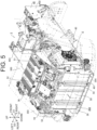
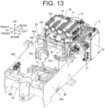
- the first electric motor is located between the second electric motor and the oil tank in a plan view.
- a work machine includes a machine body frame, an electric motor, an inverter unit, and a power transmission mechanism.
- An axle is mounted on the machine body frame.
- the electric motor generates power for driving the axle.
- the inverter unit drives the electric motor by electric power supplied from a battery unit.
- the power transmission mechanism transmits power generated by the electric motor to the axle. At least a part of the power transmission mechanism is located between the electric motor and the inverter unit in a plan view.
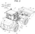
- a work machine 3 includes, in a machine body 30, a traveling unit 31, a driving unit 32, and a working unit 33.
- the "work machine” referred to in the present disclosure means various types of work machines and is, for example, a work vehicle such as a wheel loader, a backhoe (including a hydraulic excavator, a mini excavator, and the like), and a carrier.
- the work machine 3 includes the working unit 33 that is configured to be able to perform one or more works including at least a loading work.
- the work machine 3 is not limited to a "vehicle” and may be, for example, a working vessel, a working flying object such as a drone or a multicopter, or the like.
- the work machine 3 is not limited to a construction machine (construction equipment), but may also be an agricultural machine (agricultural equipment), such as a rice transplanter, a tractor, or a combined harvester, for example.
- an agricultural machine agricultural equipment
- a rice transplanter a rice transplanter
- a tractor a tractor
- a combined harvester for example.
- the work machine 3 is a riding-type wheel loader which can perform a transport work, an excavation work, a ground leveling work, a suspending work or the like in addition to the loading work as the works will be explained as an example.
- a vertical direction in a usable state of the work machine 3 will be defined as an up-down direction D1 for convenience of description.
- a front-rear direction D2 and a left-right direction D3 are defined with reference to a direction as viewed from a user (operator) on board (the driving unit 32 of) the work machine 3.
- each of the directions used in this embodiment is a direction that is defined with the machine body 30 of the work machine 3 as a reference, and a direction in which the machine body 30 moves in a forward travel of the work machine 3 is a "front", and a direction in which the machine body 30 moves in a reverse travel of the work machine 3 is a "rear".
- a direction in which the machine body 30 moves at a right turn of the work machine 3 is a "right”
- a direction in which the machine body 30 moves at a left turn of the work machine 3 is a "left”.
- these directions are not meant to limit a direction in which the work machine 3 is used (direction during use).
- the working unit 33 is driven in accordance with an operation of a user (operator) on board the driving unit 32 and performs a work such as a loading work.
- the traveling unit 31 has a traveling function, and is so configured as to be capable of traveling (including swiveling) on the ground.
- the traveling unit 31 includes, for example, a pair of left and right front wheels 311 and a pair of left and right rear wheels 312.
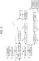
- the traveling unit 31 further includes a steering cylinder 313 (see FIG. 3 ) for steering.
- the machine body 30 is of a center-folding type and is configured in such a manner that the machine body 30 is folded at a connecting portion provided at a position between the front wheels 311 and the rear wheels 312.
- the machine body 30 travels while turning to the right direction by being driven forward by the traveling unit 31.
- the front portion 301 of the machine body 30 where the front wheels 311 are provided is bent to the left with respect to the rear portion 302 where the rear wheels 312 are provided
- the machine body 30 travels while turning to the left direction by being driven forward by the traveling unit 31.
- the steering of the traveling unit 31 as above is performed by the front portion 301 of the machine body 30 driven to swing (rotate in both directions) about the connecting portion by the steering cylinder 313 in conjunction with the operation of a steering wheel of an operation device.
- the work machine 3 drives the axle 34 of the traveling unit 31 and the hydraulic pump 11 by separate electric motors (the first electric motor 41 and the second electric motor 42).
- the first electric motor 41 may be simply referred to as an "electric motor 41".
Landscapes
- Engineering & Computer Science (AREA)
- Mining & Mineral Resources (AREA)
- Civil Engineering (AREA)
- General Engineering & Computer Science (AREA)
- Structural Engineering (AREA)
- Power Engineering (AREA)
- Operation Control Of Excavators (AREA)
- Component Parts Of Construction Machinery (AREA)
Applications Claiming Priority (2)
| Application Number | Priority Date | Filing Date | Title |
|---|---|---|---|
| JP2023146602A JP2025039981A (ja) | 2023-09-11 | 2023-09-11 | 作業機械 |
| JP2023146601A JP2025039980A (ja) | 2023-09-11 | 2023-09-11 | 作業機械 |
Publications (2)
| Publication Number | Publication Date |
|---|---|
| EP4520875A2 true EP4520875A2 (de) | 2025-03-12 |
| EP4520875A3 EP4520875A3 (de) | 2025-06-25 |
Family
ID=92542729
Family Applications (1)
| Application Number | Title | Priority Date | Filing Date |
|---|---|---|---|
| EP24196514.4A Pending EP4520875A3 (de) | 2023-09-11 | 2024-08-26 | Arbeitsmaschine |
Country Status (1)
| Country | Link |
|---|---|
| EP (1) | EP4520875A3 (de) |
Citations (2)
| Publication number | Priority date | Publication date | Assignee | Title |
|---|---|---|---|---|
| JP2012201187A (ja) | 2011-03-24 | 2012-10-22 | Komatsu Ltd | バッテリ駆動のホイールローダ |
| JP2021055359A (ja) | 2019-09-30 | 2021-04-08 | 株式会社小松製作所 | モータグレーダ |
Family Cites Families (1)
| Publication number | Priority date | Publication date | Assignee | Title |
|---|---|---|---|---|
| DE112013000458T5 (de) * | 2013-01-08 | 2014-09-04 | Komatsu Ltd. | Batteriebetriebener Gabelstapler |
-
2024
- 2024-08-26 EP EP24196514.4A patent/EP4520875A3/de active Pending
Patent Citations (2)
| Publication number | Priority date | Publication date | Assignee | Title |
|---|---|---|---|---|
| JP2012201187A (ja) | 2011-03-24 | 2012-10-22 | Komatsu Ltd | バッテリ駆動のホイールローダ |
| JP2021055359A (ja) | 2019-09-30 | 2021-04-08 | 株式会社小松製作所 | モータグレーダ |
Also Published As
| Publication number | Publication date |
|---|---|
| EP4520875A3 (de) | 2025-06-25 |
Similar Documents
| Publication | Publication Date | Title |
|---|---|---|
| EP4170098B1 (de) | Technisches gebiet der elektrischen arbeitsmaschine | |
| CN102686805B (zh) | 电动式工程机械 | |
| CN106661862A (zh) | 混合动力式作业机 | |
| EP4306723A1 (de) | Elektrische arbeitsmaschine | |
| EP2256258A2 (de) | Arbeitsmaschine | |
| US10184227B2 (en) | Work machine | |
| EP4306724A1 (de) | Elektrische arbeitsmaschine | |
| JP2004169466A (ja) | 建設機械の機器配置構造 | |
| EP4520566A1 (de) | Arbeitsmaschine | |
| EP4190626A1 (de) | Elektrische arbeitsmaschine | |
| EP4520875A2 (de) | Arbeitsmaschine | |
| US20250019929A1 (en) | Swivel working machine | |
| EP4306725A1 (de) | Baumaschine | |
| JP2025039984A (ja) | 作業機械 | |
| JP2025039983A (ja) | 作業機械 | |
| JP2025039982A (ja) | 作業機械 | |
| JP2025039981A (ja) | 作業機械 | |
| JP2025039980A (ja) | 作業機械 | |
| WO2024155404A1 (en) | Removable system pack for electric work machine | |
| EP4524326A1 (de) | Elektrische arbeitsmaschine | |
| EP4726111A1 (de) | Arbeitsmaschine | |
| EP4481122B1 (de) | Elektrische arbeitsmaschine | |
| EP4707471A1 (de) | Arbeitsmaschine | |
| EP4523949A1 (de) | Elektrische arbeitsmaschine | |
| KR20240010429A (ko) | 전기 작업 기계 |
Legal Events
| Date | Code | Title | Description |
|---|---|---|---|
| PUAI | Public reference made under article 153(3) epc to a published international application that has entered the european phase |
Free format text: ORIGINAL CODE: 0009012 |
|
| STAA | Information on the status of an ep patent application or granted ep patent |
Free format text: STATUS: THE APPLICATION HAS BEEN PUBLISHED |
|
| AK | Designated contracting states |
Kind code of ref document: A2 Designated state(s): AL AT BE BG CH CY CZ DE DK EE ES FI FR GB GR HR HU IE IS IT LI LT LU LV MC ME MK MT NL NO PL PT RO RS SE SI SK SM TR |
|
| PUAL | Search report despatched |
Free format text: ORIGINAL CODE: 0009013 |
|
| AK | Designated contracting states |
Kind code of ref document: A3 Designated state(s): AL AT BE BG CH CY CZ DE DK EE ES FI FR GB GR HR HU IE IS IT LI LT LU LV MC ME MK MT NL NO PL PT RO RS SE SI SK SM TR |
|
| RIC1 | Information provided on ipc code assigned before grant |
Ipc: E02F 9/20 20060101ALI20250520BHEP Ipc: E02F 9/08 20060101AFI20250520BHEP |
|
| STAA | Information on the status of an ep patent application or granted ep patent |
Free format text: STATUS: REQUEST FOR EXAMINATION WAS MADE |
|
| 17P | Request for examination filed |
Effective date: 20251218 |