EP4520687A1 - Transport facility - Google Patents
Transport facility Download PDFInfo
- Publication number
- EP4520687A1 EP4520687A1 EP23815495.9A EP23815495A EP4520687A1 EP 4520687 A1 EP4520687 A1 EP 4520687A1 EP 23815495 A EP23815495 A EP 23815495A EP 4520687 A1 EP4520687 A1 EP 4520687A1
- Authority
- EP
- European Patent Office
- Prior art keywords
- height
- transport
- article
- transport vehicle
- support surface
- Prior art date
- Legal status (The legal status is an assumption and is not a legal conclusion. Google has not performed a legal analysis and makes no representation as to the accuracy of the status listed.)
- Pending
Links
Images






Classifications
-
- B—PERFORMING OPERATIONS; TRANSPORTING
- B65—CONVEYING; PACKING; STORING; HANDLING THIN OR FILAMENTARY MATERIAL
- B65G—TRANSPORT OR STORAGE DEVICES, e.g. CONVEYORS FOR LOADING OR TIPPING, SHOP CONVEYOR SYSTEMS OR PNEUMATIC TUBE CONVEYORS
- B65G1/00—Storing articles, individually or in orderly arrangement, in warehouses or magazines
- B65G1/02—Storage devices
- B65G1/04—Storage devices mechanical
- B65G1/137—Storage devices mechanical with arrangements or automatic control means for selecting which articles are to be removed
- B65G1/1373—Storage devices mechanical with arrangements or automatic control means for selecting which articles are to be removed for fulfilling orders in warehouses
- B65G1/1378—Storage devices mechanical with arrangements or automatic control means for selecting which articles are to be removed for fulfilling orders in warehouses the orders being assembled on fixed commissioning areas remote from the storage areas
-
- B—PERFORMING OPERATIONS; TRANSPORTING
- B66—HOISTING; LIFTING; HAULING
- B66F—HOISTING, LIFTING, HAULING OR PUSHING, NOT OTHERWISE PROVIDED FOR, e.g. DEVICES WHICH APPLY A LIFTING OR PUSHING FORCE DIRECTLY TO THE SURFACE OF A LOAD
- B66F9/00—Devices for lifting or lowering bulky or heavy goods for loading or unloading purposes
- B66F9/06—Devices for lifting or lowering bulky or heavy goods for loading or unloading purposes movable, with their loads, on wheels or the like, e.g. fork-lift trucks
- B66F9/063—Automatically guided
-
- B—PERFORMING OPERATIONS; TRANSPORTING
- B65—CONVEYING; PACKING; STORING; HANDLING THIN OR FILAMENTARY MATERIAL
- B65G—TRANSPORT OR STORAGE DEVICES, e.g. CONVEYORS FOR LOADING OR TIPPING, SHOP CONVEYOR SYSTEMS OR PNEUMATIC TUBE CONVEYORS
- B65G1/00—Storing articles, individually or in orderly arrangement, in warehouses or magazines
- B65G1/02—Storage devices
- B65G1/04—Storage devices mechanical
- B65G1/0492—Storage devices mechanical with cars adapted to travel in storage aisles
-
- B—PERFORMING OPERATIONS; TRANSPORTING
- B65—CONVEYING; PACKING; STORING; HANDLING THIN OR FILAMENTARY MATERIAL
- B65G—TRANSPORT OR STORAGE DEVICES, e.g. CONVEYORS FOR LOADING OR TIPPING, SHOP CONVEYOR SYSTEMS OR PNEUMATIC TUBE CONVEYORS
- B65G65/00—Loading or unloading
-
- B—PERFORMING OPERATIONS; TRANSPORTING
- B66—HOISTING; LIFTING; HAULING
- B66F—HOISTING, LIFTING, HAULING OR PUSHING, NOT OTHERWISE PROVIDED FOR, e.g. DEVICES WHICH APPLY A LIFTING OR PUSHING FORCE DIRECTLY TO THE SURFACE OF A LOAD
- B66F9/00—Devices for lifting or lowering bulky or heavy goods for loading or unloading purposes
- B66F9/06—Devices for lifting or lowering bulky or heavy goods for loading or unloading purposes movable, with their loads, on wheels or the like, e.g. fork-lift trucks
- B66F9/075—Constructional features or details
- B66F9/12—Platforms; Forks; Other load supporting or gripping members
-
- G—PHYSICS
- G05—CONTROLLING; REGULATING
- G05D—SYSTEMS FOR CONTROLLING OR REGULATING NON-ELECTRIC VARIABLES
- G05D1/00—Control of position, course, altitude or attitude of land, water, air or space vehicles, e.g. using automatic pilots
- G05D1/20—Control system inputs
- G05D1/22—Command input arrangements
- G05D1/221—Remote-control arrangements
- G05D1/225—Remote-control arrangements operated by off-board computers
-
- G—PHYSICS
- G05—CONTROLLING; REGULATING
- G05D—SYSTEMS FOR CONTROLLING OR REGULATING NON-ELECTRIC VARIABLES
- G05D1/00—Control of position, course, altitude or attitude of land, water, air or space vehicles, e.g. using automatic pilots
- G05D1/20—Control system inputs
- G05D1/24—Arrangements for determining position or orientation
- G05D1/244—Arrangements for determining position or orientation using passive navigation aids external to the vehicle, e.g. markers, reflectors or magnetic means
-
- B—PERFORMING OPERATIONS; TRANSPORTING
- B65—CONVEYING; PACKING; STORING; HANDLING THIN OR FILAMENTARY MATERIAL
- B65G—TRANSPORT OR STORAGE DEVICES, e.g. CONVEYORS FOR LOADING OR TIPPING, SHOP CONVEYOR SYSTEMS OR PNEUMATIC TUBE CONVEYORS
- B65G2201/00—Indexing codes relating to handling devices, e.g. conveyors, characterised by the type of product or load being conveyed or handled
- B65G2201/02—Articles
- B65G2201/0297—Wafer cassette
-
- G—PHYSICS
- G05—CONTROLLING; REGULATING
- G05D—SYSTEMS FOR CONTROLLING OR REGULATING NON-ELECTRIC VARIABLES
- G05D2101/00—Details of software or hardware architectures used for the control of position
- G05D2101/22—Details of software or hardware architectures used for the control of position using off-board distributed computer resources for performing calculations, e.g. cloud-based
-
- G—PHYSICS
- G05—CONTROLLING; REGULATING
- G05D—SYSTEMS FOR CONTROLLING OR REGULATING NON-ELECTRIC VARIABLES
- G05D2105/00—Specific applications of the controlled vehicles
- G05D2105/20—Specific applications of the controlled vehicles for transportation
- G05D2105/28—Specific applications of the controlled vehicles for transportation of freight
-
- G—PHYSICS
- G05—CONTROLLING; REGULATING
- G05D—SYSTEMS FOR CONTROLLING OR REGULATING NON-ELECTRIC VARIABLES
- G05D2107/00—Specific environments of the controlled vehicles
- G05D2107/70—Industrial sites, e.g. warehouses or factories
Definitions
- the present invention relates to a transport facility that includes a transfer point having a placement surface on which an article is placeable, and a transport vehicle including a transfer device configured to transfer the article to and from the transfer point and a carriage body configured to travel while supporting the transfer device.
- Patent Document 1 JP 6571916B discloses an example of this type of transport facility.
- the reference numerals in parentheses in the description of the background section are those used in Patent Document 1.
- a transport vehicle (1a) includes a carriage body (11) and a transfer device (12a), as shown in FIGS. 12 to 16 of Patent Document 1.
- the carriage body (11) can rotate independently of the transfer device (12a) and change its travel direction without changing the orientation of an article (9) that is supported by the transfer device (12a).
- the transfer device (12a) has a support surface for supporting the article (9) from below.
- the transfer device (12a) can change the height of the support surface.
- the transport vehicle (11a) transfers the article (9) between the support surface of the transfer device (12a) and a conveyor (C1) by raising and lowering the transfer device (12a) while being positioned below a transfer point (e.g., the conveyor C1).
- Patent Document 1 JP 6571916B
- Patent Document 1 does not specifically disclose the relationship between the traveling state of the transport vehicle and the height of the support surface (the surface of the transfer device for supporting the article).
- the height of the support surface affects the stability of the article being supported.
- the stability of the article affects the travel speed of the transport vehicle. Further, the travel speed of the transport vehicle affects the transport time of the article. That is, the relationship between the traveling state of the transport vehicle and the height of the support surface may affect the transport time of the article.
- a transport facility includes:
- the travel speed of the transport vehicle is unlikely to be high if the straight distance is within the predetermined distance.
- the carriage body can travel without making the orientation of the article unstable.
- the transport vehicle can reach the directional change position where the transport vehicle is to perform the turning operation while maintaining the height of the support surface at the second height.
- the transport vehicle can transition to the turning operation at this directional change position without changing the height of the support surface. Accordingly, the transport time of the article can be shortened.
- the center of gravity of the transport vehicle can be lowered by positioning the support surface to the third height if the straight distance is longer than the predetermined distance. The transport vehicle can therefore travel at high speed while stabilizing the orientation of the article. Accordingly, the transport time of the article can also be shortened from this point.
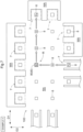
- a transport facility 100 includes transfer points 7 having placement surfaces 7f on which articles 9 are to be placed, and transport vehicles 1 each including a transfer device 20 that transfers an article 9 to and from a transfer point 7 and a carriage body 10 that travels while supporting the transfer device 20, as shown in FIGS. 1 and 2 .
- the transport facility 100 of the present embodiment includes a control device C (see FIG. 4 ).
- the control device C is configured, for example, to manage a transport schedule for the entire facility and to give the transport vehicles 1 transport commands.
- the transport facility 100 of the present embodiment has a travel area RA in which the transport vehicle 1 travels, and a work area WA in which work for articles 9 is performed.
- the transport facility 100 of the present embodiment includes a carry-in section 61 in which articles 9 are carried in from outside the facility, a discharge section 62 in which articles 9 are discharged outside the facility, an automated storage (not shown) for storing articles 9, a loading section 51 in which articles 9 are loaded into the automated storage, and an unloading section 52 in which articles 9 are unloaded from the automated storage, as shown in FIG. 1 .
- the transport vehicle 1 When delivering an article 9 to the transfer point 7, the transport vehicle 1 enters between the plurality of article receivers 720 in a plan view with the support surface 21f, which is supporting the article 9, positioned at the first height H1.
- the first height H1 is set to a position higher than the upper end of the regulator 721 of each article receiver 720, as mentioned above. This can prevent the support 21 and the article 9 supported thereby from interfering with the regulator 721 while the transport vehicle 1 enters between the article receivers 720.
- the transport vehicle 1 When receiving an article 9 from the transfer point 7, the transport vehicle 1 that has entered between the plurality of article receivers 720 in a plan view raises the support surface 21f from the second height H2 or the third height H3 to the first height H1 to receive the article 9, and thereafter exits from between the article receivers 720 while maintaining the height of the support surface 21f at the first height H1. This can prevent the support 21 and the article 9 supported thereby from interfering with the regulator 721 while the transport vehicle 1 exits from between the article receivers 720.
- An article 9 is transferred in the carry-in section 61, the discharge section 62, the loading section 51, or the unloading section 52, among the transfer points 7, as follows. That is, the transport vehicle 1 transfers an article 9 to and from the transfer point 7 (the carry-in section 61, the discharge section 62, the loading section 51, or the unloading section 52) by raising and lowering the support surface 21f between the first height H1 and the second height H2 or the third height H3 with the support 21 positioned between the two transport units 710 in a plan view. When delivering the article 9 to the transfer point 7, the transport vehicle 1 enters between the two transport units 710 in a plan view with the support surface 21f, which is supporting the article 9, positioned at the first height H1.
- the transport vehicle 1 When receiving an article 9 from the transfer point 7, the transport vehicle 1 that has entered between the two transport units 710 in a plan view raises the support surface 21f from the second height H2 or the third height H3 to the first height H1 to receive the article 9, and thereafter exits from between the two transport units 710 while maintaining the height of the support surface 21f at the first height H1.
- the transport vehicle 1 of the present embodiment includes auxiliary supports 30 that assist the support 21 in supporting an article 9.
- Each auxiliary support 30 has an auxiliary support surface 30f whose height is fixed.
- the auxiliary supports 30 are fixed to the upper surface of the carriage body 10, and their positions relative to the carriage body 10 are fixed.
- auxiliary supports 30 of the present embodiment are separated from each other with the support 21 therebetween in a plan view, as shown in FIG. 3 .
- a plurality of (four in the example shown) auxiliary supports 30 are separated from each other around the support 21 in a plan view.
- the first height H1 and the second height H2 are higher than the height of the auxiliary support surfaces 30f, as shown in FIG. 2 .
- the third height H3 is the same as or lower than the height of the auxiliary support surfaces 30f.
- the third height H3 of the present embodiment is lower than the height of the auxiliary support surfaces 30f.
- the appropriate orientation (appropriate orientation in a plan view) of the article 9 is different for each of the plurality of transfer points 7.
- the transfer points 7 adjacent to the work area WA require the orientation of the article 9 to be suitable for performing the work for this article 9.
- the other transfer points 7, namely the carry-in section 61, the discharge section 62, the loading section 51, and the unloading section 52, require the orientation of the article 9 to be suitable for transporting this article 9.
- the transport vehicle 1 performs a turning operation on the spot to change the travel direction (see FIG. 3 ), as mentioned above.
- the orientation of the article 9 in a plan view is changed using the turning operation of the transport vehicle 1.
- the turning operation of the transport vehicle 1 is prevented from changing the orientation of the article 9 in a plan view. The following is the detailed description.
- the transport vehicle 1 performs at least two types of turning operations, namely a relative turning operation, which does not involve a change of the orientation of the article 9 in a plan view, and an integral turning operation, which involves a change of the orientation of the article 9 in a plan view.
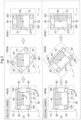
- FIG. 3(a) shows the transport vehicle 1 performing the relative turning operation.
- FIG. 3(b) shows the transport vehicle 1 performing the integral turning operation.
- the support 21 is turned by the turner 23 in the opposite direction to the direction in which the carriage body 10 turns, independently of the turning of the carriage body 10 (see FIG. 3(a) ).
- the support 21 is not turned by the turner 23, but is turned by the turning of the carriage body 10, in the same direction as the turning direction of the carriage body 10 (see FIG. 3(b) ).
- half of the support 21 is hatched in order to facilitate the understanding of the orientation of the support 21.
- the transport vehicle 1 performs a turning operation (relative turning operation) with the support surface 21f positioned at the second height H2 in the case of changing the direction of the carriage body 10 without changing the orientation in a plan view of the article 9 supported by the support surface 21f by causing the turner 23 to turn the support 21 relative to the carriage body 10, as shown in FIGS. 2 and 3 .
- the article 9 is supported by the support 21 or the auxiliary support 30 (the carriage body 10) while the transport vehicle 1 supports the article 9.
- the article 9 is supported only by the support 21 while the support surface 21f is positioned at the second height H2, as mentioned above. In this case, the carriage body 10 (the auxiliary support 30) does not serve to support the article 9.
- positioning the support surface 21f at the second height H2 can prevent the directional change (turning) of the carriage body 10 from affecting the orientation of the article 9.
- the relative turning operation which does not involve a change of the orientation of the article 9 in a plan view, can thus be performed appropriately.
- the transport vehicle 1 of the present embodiment turns the support 21 in the opposite direction to the turning direction of the carriage body 10 at the same turning angle as the turning angle of the carriage body 10.
- the support 21 of the present embodiment has a regular N-sided polygonal shape (N is an integer greater than or equal to three) in a plan view, and the turner 23 turns the support 21 in 360/N degree increments relative to the carriage body 10. This allows the relationship in a plan view between the outer shape of the support 21 and the carriage body 10 to be the same even when the transport vehicle 1 performs a turning operation without the support 21 changing its orientation in a plan view.
- the transport vehicle 1 performs a turning operation (integral turning operation) with the support surface 21f positioned at the third height H3, as shown in FIGS. 2 and 3 . That is, the transport vehicle 1 performs a turning operation (integral turning operation) with the support surface 21f positioned at the third height H3 in the case of changing the orientation in a plan view of the article 9 supported by the support surface 21f in conjunction with the turning operation.
- the article 9 is supported by the support 21 or the auxiliary support 30 (carriage body 10) while the transport vehicle 1 supports the article 9, as mentioned above.
- the article 9 is supported only by the support 21 while the support surface 21f is positioned at the second height H2. Meanwhile, upon this support surface 21f being positioned at the third height H3, the article 9, which has been supported by the support surface 21f, is then supported by the auxiliary support surface 30f, which is positioned at a position higher than the third height H3. In this case, the support 21 does not serve to support the article 9. Therefore, positioning the support surface 21f at the third height H3 makes the orientation of the article 9 dependent on the directional change (turning) of the carriage body 10. The integral turning operation involving a change of the orientation of the article 9 in a plan view can thus be performed appropriately.
- the transport vehicle 1 turns the carriage body 10 clockwise by 90 degrees in a plan view.
- This turns the support 21, which is not driven by the turner 23, clockwise by 90 degrees together with the carriage body 10.
- the integral turning operation changes the orientation of the carriage body 10 and the orientation of the support 21 as shown in the figure.
- the carriage body 10 of the present embodiment can travel at a predetermined reference speed Vs (see FIG. 8 ), as shown in FIG. 1 .
- the reference speed Vs in this example is the highest speed of the carriage body 10.
- the reference speed Vs (the highest speed in this example) is determined as appropriate based on, for example, the management of the facility.
- the control device C (see FIG. 4 ) in this example can set the travel speed V of the carriage body 10 to the reference speed Vs.
- the letter "V" in FIG. 1 indicates the actual travel speed V of the carriage body 10. If the control device C sets the travel speed V of the carriage body 10 to the reference speed Vs, for example, the control device C performs feedback control on the travel speed V of the carriage body 10 with the reference speed Vs as a target value.
- the control device C of the present embodiment includes a host control device Ct that manages the entire facility, and a transport control device C1 that is installed in each transport vehicle 1 and controls functional units of the transport vehicle 1, as shown in FIG. 4 .
- the host control device Ct and the transport control device C1 communicate with each other.
- the host control device Ct designates the transport source Pd and the transport destination Pa of each article 9, and outputs a transport command designating the transport route R from the transport source Pd to the transport destination Pa to a corresponding transport control device C1 (the transport vehicle 1).
- the transport control device C1 that has received the transport command controls each functional unit of the transport vehicle 1 in which it is installed, in accordance with the transport command.
- the host control device Ct and the transport control device C1 each have a processor such as a microcomputer, and a peripheral circuit such as a memory, for example. Each function or processing is realized by cooperation of these pieces of hardware and programs executed on the processors such as a computer.
- the host control device Ct and the transport control device C1 may be collectively referred to simply as the "control device C".
- FIGS. 5 and 6 a description is given of an example in which the transport vehicle 1 transports an article 9 from a transport source Pd to a transport destination Pa, with reference to FIGS. 5 and 6 .
- the transport vehicle 1, the article 9, and other elements are omitted for convenience of illustration.
- FIG. 5 shows a transport route R of the transport vehicle 1 in the case where the orientation of the article 9 at the transfer point 7 serving as the transport source Pd is the same as the orientation of the article 9 at the transfer point 7 serving as the transport destination Pa.
- FIG. 6 shows the height of the support surface 21f, the set speed of the carriage body 10, and the operation of the transport vehicle 1 at each point along the transport route R in this case.
- the transport route R is set so as to connect the detection target section 8 at the transport source Pd, the detection target section 8 at a point A, the detection target section 8 at a point B, the detection target section 8 at a point C, and the detection target section 8 at the transport destination Pa.
- the transport vehicle 1 travels through the transport route R in the order from the transport source Pd to the point A, the point B, the point C, and the transport destination Pa.
- the transport vehicle 1 receives the article 9 from the transfer point 7 of the transport source Pd by changing the height of the support surface 21f from the third height H3 to the first height H1 at the transport source Pd, as shown in FIG. 6 .
- the travel speed V of the carriage body 10 at the transport source Pd is set lower than the reference speed Vs (V ⁇ Vs).
- the travel speed V of the transport vehicle 1 when receiving the article 9 from the transfer point 7 of the transport source Pd is set to zero. That is, the carriage body 10 is stopped.
- the transport vehicle 1 After receiving the article 9, the transport vehicle 1 starts traveling to the next point (the position of the detection target section 8) while supporting the article 9. In the example shown in FIG. 5 , the transport vehicle 1 starts traveling from the transport source Pd to the point A.
- the transport vehicle 1 travels with the support surface 21f positioned at the second height H2 if the straight distance L from the travel starting point (here, the transport source Pd) at which the transport vehicle 1 started traveling while supporting the article 9 to the directional change position 80 (here, the point B) at which the transport vehicle 1 is to perform a turning operation (relative turning operation) that does not involve a change of the orientation of the article 9 is within a predetermined distance Ls.
- the height of the support surface 21f may be changed to the second height H2 before the transport vehicle 1 starts traveling, or while the transport vehicle 1 travels after starting traveling. In the latter case, the transport vehicle 1 completes changing the height of the support surface 21f to the second height H2 before reaching the directional change position 80.
- the control device C of the present embodiment sets the transport route R from the transport source Pd to the transport destination Pa of the article 9, and determines whether the straight distance L is within the predetermined distance Ls based on the transport route R.
- the transport route R in this example is a route that combines a straight route along the first direction D1 and a straight route along the second direction D2, as mentioned above.
- the control device C calculates the straight distance L based on these straight routes that constitute the transport route R, and determines whether the straight distance L is within the predetermined distance Ls.
- the predetermined distance Ls is determined as appropriate, based on, for example, the management of the facility.
- the directional change position 80 that the transport vehicle 1 first reaches is the point B.
- the straight distance L from the transport source Pd, which is the travel starting point, to the point B is within the predetermined distance Ls (L ⁇ Ls). Accordingly, the transport vehicle 1 travels from the transport source Pd to the point B while positioning the support surface 21f at the second height H2.
- the transport vehicle 1 can position the support surface 21f at the second height H2 before reaching the directional change position 80 (the point B) where the transport vehicle 1 is to perform the relative turning operation.
- the transport vehicle 1 can therefore transition to the relative turning operation at the directional change position 80 (here, the point B) without changing the height of the support surface 21f. Consequently, the transport time of the article 9 can be shortened.
- the transport vehicle 1 in the example shown in FIGS. 5 and 6 changes the height of the support surface 21f from the first height H1 to the second height H2 while traveling from the transport source Pd to the point A.
- the travel speed V of the carriage body 10 at this time is set lower than the reference speed Vs (V ⁇ Vs).
- the transport vehicle 1 maintains the height of the support surface 21f at the second height H2.
- the travel speed V of the carriage body 10 at this time is set lower than the reference speed Vs (V ⁇ Vs). In this state, the transport vehicle 1 travels from the point A to the point B.
- the transport vehicle 1 maintains the height of the support surface 21f at the second height H2.
- the travel speed V of the carriage body 10 at this time is set lower than the reference speed Vs (V ⁇ Vs).
- the travel speed V at the point B is set to zero in this example.
- the transport vehicle 1, while stopped, performs the relative turning operation at the point B, which is the directional change position 80.
- the transport vehicle 1 thus directs the travel direction of the carriage body 10 to the next point C without changing the orientation of the article 9 in a plan view. Thereafter, the transport vehicle 1 starts traveling from the point B to the point C.
- the straight distance L from the travel starting point (here, the point B) of the transport vehicle 1 to the directional change position 80 (here, the point C) at which the transport vehicle 1 is to perform a turning operation (relative turning operation) that does not involve a change of the orientation of the article 9 is within the predetermined distance Ls (L ⁇ Ls). Accordingly, the transport vehicle 1 travels from the point B to the point C while positioning the support surface 21f at the second height H2.
- the travel starting point of the transport vehicle 1 is not limited to the starting point of the transport route R (the transport source Pd). If the transport vehicle 1 performs a turning operation, the straight distance L is determined with the point at which this turning operation was performed (in this example, the point B) as a travel starting point.
- the transport vehicle 1 changes the height of the support surface 21f from the second height H2 to the first height H1 while traveling from the point C to the transport destination Pa.
- the travel speed V of the carriage body 10 at this time is set lower than the reference speed Vs (V ⁇ Vs).
- the transport vehicle 1 delivers the article 9 to the transfer point 7 of the transport destination Pa by changing the height of the support surface 21f from the first height H1 to the third height H3.
- the travel speed V of the carriage body 10 at the transport destination Pa is set lower than the reference speed Vs (V ⁇ Vs).
- the travel speed V of the transport vehicle 1 while delivering the article 9 to the transfer point 7 of the transport destination Pa is set to zero. That is, the carriage body 10 is stopped.
- FIGS. 7 and 8 a description is given of an example in which the transport vehicle 1 transports an article 9 from a transport source Pd to a transport destination Pa, with reference to FIGS. 7 and 8 .
- the transport vehicle 1, the article 9, and other elements are omitted for convenience of illustration.
- FIG. 7 shows a transport route R of the transport vehicle 1 in the case where the orientation of the article 9 at the transfer point 7 serving as the transport source Pd is different from the orientation of the article 9 at the transfer point 7 serving as the transport destination Pa.
- FIG. 8 shows the height of the support surface 21f, the set speed of the carriage body 10, and the operation of the transport vehicle 1 at each point along the transport route R in this case.
- the transport route R is set so as to connect the detection target section 8 at the transport source Pd, the detection target section 8 at a point A, the detection target section 8 at a point B, the detection target section 8 at a point C, the detection target section 8 at a point D, and the detection target section 8 at the transport destination Pa.
- the transport vehicle 1 travels through the transport route R in the order from the transport source Pd to the point A, the point B, the point C, the point D, and the transport destination Pa.
- the transport vehicle 1 receives the article 9 from the transfer point 7 of the transport source Pd by changing the height of the support surface 21f from the third height H3 to the first height H1 at the transport source Pd, as shown in FIG. 8 .
- the travel speed V of the carriage body 10 at the transport source Pd is set lower than the reference speed Vs (V ⁇ Vs).
- the travel speed V of the transport vehicle 1 when receiving the article 9 from the transfer point 7 of the transport source Pd is set to zero. That is, the carriage body 10 is stopped.
- the transport vehicle 1 After receiving the article 9, the transport vehicle 1 starts traveling to the next point (the position of the detection target section 8) while supporting the article 9. In the example shown in FIG. 7 , the transport vehicle 1 starts traveling from the transport source Pd to the point A.
- the transport vehicle 1 travels with the support surface 21f positioned at the third height H3 regardless of whether the straight distance from the travel starting point (here, the transport source Pd) at which the transport vehicle 1 started traveling while supporting the article 9 to the directional change position 80 (here, the point B) at which the transport vehicle 1 is to perform a turning operation (integral turning operation) that involves a change of the orientation of the article 9 is within the predetermined distance.
- the directional change position 80 that the transport vehicle 1 first reaches is the point B, and the transport vehicle 1 is scheduled to perform at the point B the integral turning operation that involves a change of the orientation of the article 9.
- the transport vehicle 1 travels from the transport source Pd to the point B while positioning the support surface 21f at the third height H3.
- the transport vehicle 1 can position the support surface 21f at the third height H3 before reaching the directional change position 80 (the point B) at which the transport vehicle 1 is to perform the integral turning operation.
- the transport vehicle 1 can therefore transition to the integral turning operation at the directional change position 80 (here, the point B) without changing the height of the support surface 21f.
- the center of gravity of the transport vehicle 1 can be lowered by positioning the support surface 21f at the third height H3, thus allowing the transport vehicle 1 to travel at high speed while stabilizing the orientation of the article 9. Accordingly, the transport time of the article 9 can be shortened.
- the transport vehicle 1 in the example shown in FIGS. 7 and 8 changes the height of the support surface 21f from the first height H1 to the third height H3 while traveling from the transport source Pd to the point A.
- the travel speed V of the carriage body 10 at this time is set lower than the reference speed Vs (V ⁇ Vs).
- V ⁇ Vs the reference speed
- the support surface 21f is positioned at the first height H1
- the position of the article 9 supported by the support surface 21f is higher than while the support surface 21f is positioned at the second height H2 or the third height H3, making the orientation of the article 9 less stable accordingly.
- the carriage body 10 of the present embodiment travels at a speed lower than the reference speed Vs or stops in response to the lift 22 raising or lowering the support surface 21f between the first height H1 and the second height H2 or the third height H3. This makes it possible to change the height of the support surface 21f with high reliability in cases including a state where the height of the support surface 21f is set to the first height H1.
- the transport vehicle 1 maintains the height of the support surface 21f at the third height H3.
- the travel speed V of the carriage body 10 at this time is set lower than the reference speed Vs (V ⁇ Vs).
- the travel speed V at the point B is set to zero in this example.
- the transport vehicle 1, while stopped, performs the integral turning operation at the point B, which is the directional change position 80.
- the transport vehicle 1 thus directs the travel direction of the carriage body 10 to the point C and changes the orientation of the article 9 to the proper orientation at the transport destination Pa. Thereafter, the transport vehicle 1 starts traveling from the point B to the point C.
- the transport vehicle 1 maintains the height of the support surface 21f at the third height H3.
- the transport vehicle 1 maintains the height of the support surface 21f at the third height H3.
- the transport vehicle 1 changes the height of the support surface 21f from the third height H3 to the first height H1 while traveling from the point D to the transport destination Pa.
- the travel speed V of the carriage body 10 at this time is set lower than the reference speed Vs (V ⁇ Vs).
- the transport vehicle 1 delivers the article 9 to the transfer point 7 of the transport destination Pa by changing the height of the support surface 21f from the first height H1 to the third height H3.
- the travel speed V of the carriage body 10 at the transport destination Pa is set lower than the reference speed Vs (V ⁇ Vs).
- the travel speed V of the transport vehicle 1 while delivering the article 9 to the transfer point 7 of the transport destination Pa is set to zero. That is, the carriage body 10 is stopped.
- FIGS. 9 and 10 a description is given of an example in which the transport vehicle 1 transports the article 9 from the transport source Pd to the transport destination Pa, with reference to FIGS. 9 and 10 .
- the transport vehicle 1, the article 9, and other elements are omitted for convenience of illustration.
- the directional change position 80 that the transport vehicle 1 first reaches is the point B.
- the straight distance L from the transport source Pd, which is the travel starting point, to the point B is within the predetermined distance Ls (L ⁇ Ls). Accordingly, the transport vehicle 1 travels from the transport source Pd to the point B while positioning the support surface 21f at the second height H2.
- the transport vehicle 1 maintains the height of the support surface 21f at the second height H2.
- the travel speed V of the carriage body 10 at this time is set lower than the reference speed Vs (V ⁇ Vs). In this state, the transport vehicle 1 travels from the point A to the point B.
- the transport vehicle 1 maintains the height of the support surface 21f at the second height H2.
- the travel speed V of the carriage body 10 at this time is set lower than the reference speed Vs (V ⁇ Vs).
- the travel speed V at the point B is set to zero in this example.
- the transport vehicle 1, while stopped, performs the relative turning operation at the point B, which is the directional change position 80.
- the transport vehicle 1 thus directs the travel direction of the carriage body 10 to the next point C without changing the orientation of the article 9 in a plan view. Thereafter, the transport vehicle 1 starts traveling from the point B to the point C.
- the transport vehicle 1 travels with the support surface 21f positioned at the third height H3 if the straight distance L from the travel starting point (here, the point B) at which the transport vehicle 1 started traveling while supporting the article 9 to the directional change position 80 (here, the point E) at which the transport vehicle 1 is to perform a turning operation (relative turning operation) that does not involve a change of the orientation of the article 9 is longer than the predetermined distance Ls. If the straight distance L is longer than the predetermined distance Ls as in this case, and if the support surface 21f is not positioned at the third height H3 at the travel starting point, the height of the support surface 21f may be changed to the third height H3 before the transport vehicle 1 starts traveling or while the transport vehicle 1 travels after starting traveling.
- the transport vehicle 1 completes changing the height of the support surface 21f to the third height H3 before reaching the directional change position 80. If the straight distance L is longer than the predetermined distance Ls, the transport vehicle 1 can contribute more to shortening the transport time of the article 9 by traveling at high speed with the height of the support surface 21f set to the third height H3, which is lower than the second height H2, even if the support surface 21f needs to be positioned at the second height H2 later (i.e., the support surface 21f needs to be positioned at the second height H2 in the case of performing the relative turning operation).
- the center of gravity of the transport vehicle 1 can be lowered by positioning the support surface 21f at the third height H3, allowing the transport vehicle 1 to travel at high speed while stabilizing the orientation of the article 9, as mentioned above.
- the transport vehicle 1 of the present embodiment travels at the reference speed Vs if the straight distance L is longer than the predetermined distance Ls.
- the straight distance L from the point B, which is the travel starting point, to the point E, which is the next directional change position 80 is longer than the predetermined distance Ls (L>Ls). Accordingly, the transport vehicle 1 travels from the point B to the point E at the reference speed Vs while positioning the support surface 21f at the third height H3.
- the transport vehicle 1 changes the height of the support surface 21f from the second height H2 to the third height H3 while traveling from the point B to the point C. That is, the lift 22 of the present embodiment raises and lowers the support surface 21f between the second height H2 and the third height H3 while the carriage body 10 travels. Changing the height of the support surface 21f between the second height H2 and the third height H3 does not include a state where the height of the support surface 21f is the first height H1, thereby allowing the orientation of the article 9 to be stabilized relatively easily. Raising and lowering the support surface 21f between the second height H2 and the third height H3 while the carriage body 10 travels can contribute to shortening the transport time of the article 9 as in the above configuration.
- the travel speed V while the support surface 21f is raised and lowered between the second height H2 and the third height H3 while the transport vehicle 1 travels i.e., in the example shown in FIG. 9 , the travel speed V while the transport vehicle 1 travels from the point B to the point C, is set to the reference speed Vs.
- the travel speed V may be set lower than the reference speed Vs.
- the transport vehicle 1 maintains the height of the support surface 21f at the third height H3.
- the transport vehicle 1 maintains the height of the support surface 21f at the third height H3.
- the point E is the directional change position 80 at which the transport vehicle 1 is to perform the relative turning operation that does not involve a change of the orientation of the article 9.
- the support surface 21f needs to be positioned at the second height H2.
- the transport vehicle 1 changes the height of the support surface 21f from the third height H3 to the second height H2 while traveling from the point D to the point E. It is relatively easy to stabilize the orientation of the article 9 while changing the height of the support surface 21f between the second height H2 and the third height H3, as mentioned above.
- the transport vehicle 1 maintains the height of the support surface 21f at the second height H2.
- the travel speed V of the carriage body 10 at this time is set lower than the reference speed Vs (V ⁇ Vs).
- the travel speed V at the point E is set to zero in this example.
- the transport vehicle 1, while stopped, performs the relative turning operation at the point E, which is the directional change position 80.
- the transport vehicle 1 thus directs the travel direction of the carriage body 10 to the transport destination Pa without changing the orientation of the article 9 in a plan view. Thereafter, the transport vehicle 1 starts traveling from the point E to the transport destination Pa.
- the transport vehicle 1 changes the height of the support surface 21f from the second height H2 to the first height H1 while traveling from the point E to the transport destination Pa.
- the travel speed V of the carriage body 10 at this time is set lower than the reference speed Vs (V ⁇ Vs).
- the transport vehicle 1 delivers the article 9 to the transfer point 7 of the transport destination Pa by changing the height of the support surface 21f from the first height H1 to the third height H3.
- the travel speed V of the carriage body 10 at the transport destination Pa is set lower than the reference speed Vs (V ⁇ Vs).
- the travel speed V of the transport vehicle 1 while delivering the article 9 to the transfer point 7 of the transport destination Pa is set to zero. That is, the carriage body 10 is stopped.
- the above-described transport facility 100 can shorten the transport time of the article 9.
- a transport facility includes:
- the travel speed of the transport vehicle is unlikely to be high if the straight distance is within the predetermined distance.
- the carriage body can travel without making the orientation of the article unstable.
- the transport vehicle can reach the directional change position where the transport vehicle is to perform the turning operation while maintaining the height of the support surface at the second height.
- the transport vehicle can transition to the turning operation at this directional change position without changing the height of the support surface. Accordingly, the transport time of the article can be shortened.
- the center of gravity of the transport vehicle can be lowered by positioning the support surface to the third height if the straight distance is longer than the predetermined distance. The transport vehicle can therefore travel at high speed while stabilizing the orientation of the article. Accordingly, the transport time of the article can also be shortened from this point.
- the carriage body is capable of traveling at a predetermined reference speed, and the carriage body travels at a speed lower than the reference speed or stops while the lift raises and lowers the support surface between the first height and the second height or the third height.
- the position of the article supported by the support surface is higher than while the support surface is positioned at the second or third height, making the orientation of the article less stable accordingly.
- this configuration if the height of the support surface is changed, and this change includes a state where the height of the support surface is the first height, the carriage body travels at a speed lower than the reference speed, or stops. Therefore, it is possible to change the height of the support surface with high reliability in cases including a state where the height of the support surface is the first height.
- the lift raises and lowers the support surface between the second height and the third height while the carriage body travels.
- the orientation of the article can easily be stabilized in the case of performing a change of the height of the support surface between the second height and the third height that does not include a state where the height of the support surface is the first height.
- the travel of the carriage body and the change of the height of the support surface can be performed at the same time by changing the height of the support surface while the carriage body travels. This makes it easy to shorten the transport time.
- the transport vehicle includes auxiliary supports configured to assist the support in supporting the article,
- the article can be supported using the auxiliary support surface with the support surface positioned at the third height, thereby supporting the article more stably.
- the transport vehicle performs the turning operation with the support surface positioned at the third height in response to changing the orientation in a plan view of the article supported by the support surface in conjunction with the turning operation.
- the orientation in a plan view of the article can be changed together with the orientation of the carriage body due to the transport vehicle performing the turning operation while supporting the article using the auxiliary support surface by positioning the support surface at the third height.
- the orientation in a plan view of the article can be changed to an orientation suitable for the transfer point by the turning operation of the transport vehicle.
- the transport facility further includes a control device, and the control device sets a transport route from a transport source to a transport destination of the article, and determines based on the transport route whether the straight distance is within the predetermined distance.
- control device can more appropriately determine whether the straight distance is within the predetermined distance.
- the transport vehicle includes a detector
- a relatively simple configuration allows the traveling position of the transport vehicle to be controlled with high accuracy. Further, it is easy to flexibly change the transport route and the directional change position of the transport vehicle in accordance with, for example, the management situation of the facility.
- the support has a regular N-sided polygonal shape (N is an integer greater than or equal to three) in a plan view, and the turner turns the support in 360/N degree increments relative to the carriage body.
- the transfer point includes:
- the plurality of article receivers each have a regulator protruding upward from the placement surface and configured to regulate a position in a horizontal direction of the article placed on the placement surface, and the first height is set to a position higher than an upper end of the regulator.
- the regulator can regulate the position in the horizontal direction of the article placed at the transfer point. Further, it is possible to prevent the support and the regulator from interfering with each other even while the transport vehicle moves in and out of the transfer point with the support surface positioned at the first height.
- the technology according to the present disclosure can be applied to a transport facility that includes a transfer point having a placement surface on which an article is placed, and a transport vehicle including a transfer device configured to transfer the article to and from the transfer point and a carriage body configured to travel while supporting the transfer device.
Landscapes
- Engineering & Computer Science (AREA)
- Mechanical Engineering (AREA)
- Transportation (AREA)
- Structural Engineering (AREA)
- Civil Engineering (AREA)
- Life Sciences & Earth Sciences (AREA)
- Geology (AREA)
- Radar, Positioning & Navigation (AREA)
- Aviation & Aerospace Engineering (AREA)
- Remote Sensing (AREA)
- Physics & Mathematics (AREA)
- General Physics & Mathematics (AREA)
- Automation & Control Theory (AREA)
- Control Of Position, Course, Altitude, Or Attitude Of Moving Bodies (AREA)
- Warehouses Or Storage Devices (AREA)
- Intermediate Stations On Conveyors (AREA)
Abstract
Description
- The present invention relates to a transport facility that includes a transfer point having a placement surface on which an article is placeable, and a transport vehicle including a transfer device configured to transfer the article to and from the transfer point and a carriage body configured to travel while supporting the transfer device.
-
JP 6571916B Patent Document 1. - A transport vehicle (1a) includes a carriage body (11) and a transfer device (12a), as shown in FIGS. 12 to 16 of
Patent Document 1. The carriage body (11) can rotate independently of the transfer device (12a) and change its travel direction without changing the orientation of an article (9) that is supported by the transfer device (12a). The transfer device (12a) has a support surface for supporting the article (9) from below. The transfer device (12a) can change the height of the support surface. The transport vehicle (11a) transfers the article (9) between the support surface of the transfer device (12a) and a conveyor (C1) by raising and lowering the transfer device (12a) while being positioned below a transfer point (e.g., the conveyor C1). - Patent Document 1:
JP 6571916B -
Patent Document 1 does not specifically disclose the relationship between the traveling state of the transport vehicle and the height of the support surface (the surface of the transfer device for supporting the article). The height of the support surface affects the stability of the article being supported. The stability of the article affects the travel speed of the transport vehicle. Further, the travel speed of the transport vehicle affects the transport time of the article. That is, the relationship between the traveling state of the transport vehicle and the height of the support surface may affect the transport time of the article. - In view of the foregoing circumstances, it is desirable to realize a transport facility that can easily shorten the transport time of the article.
- A transport facility includes:
- a transfer point having a placement surface on which an article is placeable; and
- a transport vehicle including:
- a transfer device configured to transfer the article to and from the transfer point; and
- a carriage body configured to travel while supporting the transfer device,
- the transport vehicle is configured to travel along a floor and perform a turning operation to change a travel direction at a directional change position determined in accordance with a destination,
- the transfer device includes:
- a support having a support surface configured to support the article from below,
- a lift configured to raise and lower the support, and
- a turner configured to turn the support relative to the carriage body about a turning axis extending along an up-down direction,
- the lift is capable of changing a height of the support surface to a first height higher than the placement surface, a second height lower than the placement surface, and a third height lower than the second height,
- the transfer device transfers the article to and from the transfer point by raising and lowering the support surface between the first height and the second height or the third height,
- the transport vehicle performs the turning operation with the support surface positioned at the second height in response to changing a direction of the carriage body without changing an orientation in a plan view of the article supported by the support surface by causing the turner to turn the support relative to the carriage body, and
- the transport vehicle travels with the support surface positioned at the second height if a straight distance from a travel starting point at which the transport vehicle starts traveling while supporting the article to the directional change position at which the transport vehicle is to perform the turning operation that does not involve a change of the orientation of the article is within a predetermined distance, and the transport vehicle travels with the support surface positioned at the third height if the straight distance is longer than the predetermined distance.
- According to this configuration, the travel speed of the transport vehicle is unlikely to be high if the straight distance is within the predetermined distance. Thus, even if the article supported by the support surface is maintained at a relatively high position by positioning the support surface at the second height, the carriage body can travel without making the orientation of the article unstable. Further, the transport vehicle can reach the directional change position where the transport vehicle is to perform the turning operation while maintaining the height of the support surface at the second height. Thus, the transport vehicle can transition to the turning operation at this directional change position without changing the height of the support surface. Accordingly, the transport time of the article can be shortened. Furthermore, according to this configuration, the center of gravity of the transport vehicle can be lowered by positioning the support surface to the third height if the straight distance is longer than the predetermined distance. The transport vehicle can therefore travel at high speed while stabilizing the orientation of the article. Accordingly, the transport time of the article can also be shortened from this point.
- Further features and advantages of the technology according to the present disclosure will become more apparent in the description of the following illustrative and non-limiting embodiments that will be described with reference to the drawings.
-
-
FIG. 1 is a plan view of a transport facility. -
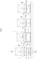
FIG. 2 depicts the height relationship between a placement surface at a transfer point and a support surface of a support. -
FIG. 3 illustrates turning operations. -
FIG. 4 is a control block diagram. -
FIG. 5 illustrates a case where the straight distance to a directional change position at which a relative turning operation is to be performed is within a predetermined distance and the orientation of an article is not changed between a transport source and a transport destination. -
FIG. 6 depicts behavior of a transport vehicle at each point in the case ofFIG. 5 . -
FIG. 7 illustrates a case of changing the orientation of an article between a transport source and a transport destination by means of an integral turning operation. -
FIG. 8 depicts behavior of the transport vehicle at each point in the case ofFIG. 7 . -
FIG. 9 illustrates a case where the straight distance to a directional change position at which a relative turning operation is to be performed is greater than a predetermined distance and the orientation of an article is not changed between a transport source and a transport destination. -
FIG. 10 depicts behavior of the transport vehicle at each point in the case ofFIG. 9 . -
FIG. 11 is a plan view of a transport vehicle according to another embodiment. - Hereinafter, embodiments of a transport facility will be described with reference to the drawings.
- A
transport facility 100 includestransfer points 7 havingplacement surfaces 7f on whicharticles 9 are to be placed, and transportvehicles 1 each including atransfer device 20 that transfers anarticle 9 to and from atransfer point 7 and acarriage body 10 that travels while supporting thetransfer device 20, as shown inFIGS. 1 and2 . Thetransport facility 100 of the present embodiment includes a control device C (seeFIG. 4 ). The control device C is configured, for example, to manage a transport schedule for the entire facility and to give thetransport vehicles 1 transport commands. - Each
article 9 of the present embodiment includes apallet 90 and one ormore loads 91 placed on thepallet 90. Eachtransport vehicle 1 transports apallet 90 with one ormore loads 91 placed thereon, or anempty pallet 90 without aload 91. Eachtransfer point 7 is configured such that apallet 90 can be directly placed therein. - The
transport facility 100 of the present embodiment has a travel area RA in which thetransport vehicle 1 travels, and a work area WA in which work forarticles 9 is performed. - In the present embodiment, a plurality of
transfer points 7 are located at positions adjacent to the travel area RA. Thus, thetransport vehicle 1 can transport anarticle 9 to each of the transfer points 7 by traveling in the travel area RA while carrying thearticle 9. - Further, some of the transfer points 7 of the present embodiment are located at positions adjacent to the work area WA. The
articles 9 transported to the transfer points 7 adjacent to the work area WA are processed by workers or robots. In the example shown, workers W are located in the work area WA. For example, the workers W in the work area WA perform the work of picking loads 91. In this picking operation, for example, a worker W performs the work of takingnecessary loads 91 out of a plurality ofloads 91 placed on apallet 90. Note that the work performed in the work area WA is not limited to the above, and may be the work of stackingloads 91 onpallets 90 or any other work. - The
transport facility 100 of the present embodiment includes a carry-in section 61 in whicharticles 9 are carried in from outside the facility, a discharge section 62 in whicharticles 9 are discharged outside the facility, an automated storage (not shown) for storingarticles 9, a loading section 51 in whicharticles 9 are loaded into the automated storage, and an unloading section 52 in whicharticles 9 are unloaded from the automated storage, as shown inFIG. 1 . - The carry-in section 61, the discharge section 62, the loading section 51, and the unloading section 52 of the present embodiment each include a conveyor for transporting
articles 9. The conveyor has twotransport units 710 spaced apart from each other in a direction (width direction) perpendicular to a transport direction in whicharticles 9 are transported. Each of the twotransport units 710transports articles 9 along the transport direction while supporting thearticles 9 from below. That is, the upper surface of each of the twotransport units 710 that constitute the conveyor serves as aplacement surface 7f on whicharticles 9 are placed. The conveyor in this example is constituted by a chain conveyor that transportsarticles 9 using a pair of chains (transport units 710). Each conveyor serves as a target point for the transfer ofarticles 9 to and from thetransfer device 20 of thetransport vehicle 1. That is, the conveyors in the carry-in section 61, the discharge section 62, the loading section 51, and the unloading section 52 of the present embodiment each correspond to thetransfer point 7. In other words, the carry-in section 61, the discharge section 62, the loading section 51, and the unloading section 52 each correspond to thetransfer point 7. - Each
transfer point 7 of the present embodiment includes a plurality ofcolumns 72 spaced apart from each other at least in the vehicle width direction of the transport vehicle 1 (seeFIG. 2 ), andarticle receivers 720 at upper portions ofrespective columns 72. In this example, the transfer points 7 adjacent to the work area WA, among the plurality oftransfer points 7 in thetransport facility 100, each have the plurality ofcolumns 72 and thearticle receivers 720 at the upper portions of therespective columns 72. Note that the carry-in section 61, the discharge section 62, the loading section 51, and the unloading section 52, which serve as the transfer points 7, each include a pair of transport units 710 (chains in this example) capable of supportingarticles 9 from below, as mentioned above. - Each of the
article receivers 720 has aplacement surface 7f on which anarticle 9 is placed. In the present embodiment, eachtransfer point 7 adjacent to the work area WA has four columns 72 (four article receivers 720), as shown inFIG. 1 . Four corners of anarticle 9 placed at thetransfer point 7 are supported from below by the four columns 72 (four article receivers 720). - Each of the
article receivers 720 of the present embodiment has aregulator 721 that protrudes upward from theplacement surface 7f and regulates the position in the horizontal direction of thearticle 9 placed on theplacement surface 7f, as shown inFIGS. 1 and2 . Theregulators 721 of thearticle receivers 720 surround the outer edge of thearticle 9 from the outer side in the horizontal direction, with thearticle 9 placed on the placement surfaces 7f of thearticle receivers 720. This makes it possible to regulate the position of thearticle 9 placed at thetransfer point 7 such that thearticle 9 does not move in the horizontal direction. - The
transport vehicle 1 of the present embodiment has a detector 40 (seeFIG. 4 ). Also,detection target sections 8 to be detected by thedetector 40 are provided at a plurality of locations on the floor. Eachdetection target section 8 stores or displays information indicating the position at which thisdetection target section 8 is located. Thetransport vehicle 1 can ascertain its own current location by detecting adetection target section 8 using thedetector 40. - A plurality of
detection target sections 8 are spaced apart from each other in a regular arrangement in the travel area RA of the present embodiment. Further, thedetection target sections 8 are also provided at the respective transfer points 7. In this example, thedetection target sections 8 are provided at points on the floor corresponding to the respective transfer points 7. Thetransport vehicle 1 travels on the floor while correcting its own current position (estimated current position) based on the results of detecting thedetection target sections 8 using thedetector 40. Eachdetection target section 8 in this example is constituted by an identification code such as a one-dimensional or two-dimensional code. Thedetector 40 of thetransport vehicle 1 is constituted by a code reader that reads the identification code. However, there is no limitation to this configuration. For example, eachdetection target section 8 may be constituted by an IC tag, and thedetector 40 may be constituted by an IC tag reader. Alternatively, eachdetection target section 8 may be constituted by a mark, and thedetector 40 may be constituted by an image capture device that captures an image of the mark. - The control device C (see
FIG. 4 ) of the present embodiment sets a transport route R from a transport source Pd to a transport destination Pa of eacharticle 9, as shown inFIG. 5 and other figures. The transport route R is set so as to connect a plurality ofdetection target sections 8. The transport source Pd of the present embodiment is defined based on the position of adetection target section 8 located at atransfer point 7 serving as the transport source Pd. The transport destination Pa is defined based on the position of adetection target section 8 located at atransfer point 7 serving as the transport destination Pa. The transport route R is set so as to connect a plurality ofdetection target sections 8 present between thedetection target section 8 corresponding to the transport source Pd and thedetection target section 8 corresponding to the transport destination Pa. Assuming that two directions (here, two horizontal directions) perpendicular to each other in a plan view are defined as a first direction D1 and a second direction D2, the transport route R in this example is set so as to connectdetection target sections 8 adjacent to each other in the first direction D1 ordetection target sections 8 adjacent to each other in the second direction D2. Therefore, the transport route R in this example is a route that combines a straight route along the first direction D1 and a straight route along the second direction D2. Thetransport vehicle 1 traveling along the transport route R travels straight along the first direction D1 or travels straight along the second direction D2. - The
transport vehicle 1 is configured to travel along the floor and perform a turning operation to change the travel direction at a directional change position 80 (seeFIG. 5 and other figures), which is determined in accordance with a destination, as shown inFIGS. 1 and2 . Here, the "destination" refers to thetransfer point 7 serving as the transport destination Pa, as shown inFIG. 5 and other figures. Thedirectional change position 80 is determined based on the positions of a plurality ofdetection target sections 8. Specifically, the position of adetection target section 8 located in a region where the transport route R curves (in this example, a region where the transport route R turns at a right angle), out of the plurality ofdetection target sections 8 constituting the transport route R, is determined as adirectional change position 80. - The
transport vehicle 1 includes thecarriage body 10 and thetransfer device 20 supported by thecarriage body 10, as mentioned above. - The
carriage body 10 includes atravel unit 11. Thetravel unit 11 of the present embodiment includes a plurality ofwheels 11a, which are spaced apart from each other at least in the vehicle width direction, and a travel driver (not shown) that drives thewheels 11a to rotate. The travel driver is constituted by an electric motor or the like, for example. - The
transfer device 20 transfers anarticle 9 to and from atransfer point 7. While thetransport vehicle 1 is at atransfer point 7, thetransfer device 20 delivers anarticle 9 to thetransfer point 7 or receives anarticle 9 from thetransfer point 7. - The
transfer device 20 includes asupport 21 having asupport surface 21f for supporting anarticle 9 from below, alift 22 that raises and lowers thesupport 21, and a turner 23 (seeFIG. 4 ) that turns thesupport 21 about a turning axis Ax, which extends along the up-down direction, relative to thecarriage body 10, as shown inFIG. 2 . - The
support 21 of the present embodiment is rectangular in a plan view (seeFIG. 3 ). More specifically, thesupport 21 is square in a plan view. Thesupport 21 has a size that allows thesupport 21 to pass in the up-down direction between the plurality ofplacement surfaces 7f of atransfer point 7, and is smaller than the spacing between theplacement surfaces 7f in thetransfer point 7 in a plan view. - The
turner 23 drives thesupport 21 to turn about the turning axis Ax that extends along the up-down direction. Theturner 23 is constituted by an electric motor or the like, for example. - The
lift 22 of the present embodiment includes ashaft member 22a and a lift driver (not shown) for moving theshaft member 22a back and forth along the up-down direction. In this example, thesupport 21 is joined to an upper end of theshaft member 22a. Thesupport 21 moves upward and downward along the up-down direction due to theshaft member 22a being driven by the lift driver to move back and forth along the up-down direction. The lift driver is constituted by an electric motor or the like, for example. - The
lift 22 can change the height of thesupport surface 21f to a first height H1, which is higher than the placement surfaces 7f, a second height H2, which is lower than theplacement surfaces 7f, and a third height H3, which is lower than the second height H2. That is, thelift 22 can change the height of thesupport surface 21f between at least three levels. - The height of the placement surfaces 7f (hereinafter also referred to simply as a "placement surface height H7") is fixed in the present embodiment. The first height H1 is higher than the placement surface height H7. The second height H2 and the third height H3 are lower than the placement surface height H7. That is, the placement surface height H7 is set between the first height H1 and the second and third heights H2 and H3. The
transfer device 20 transfers anarticle 9 to and from thetransfer point 7 by raising and lowering thesupport surface 21f between the first height H1 and the second height H2 or the third height H3. Specifically, thetransfer device 20 delivers thearticle 9 to theplacement surfaces 7f by changing the height of thesupport surface 21f supporting thearticle 9 from the first height H1 to the second height H2 or the third height H3. Thetransfer device 20 receives thearticle 9 supported on theplacement surfaces 7f by changing the height of thesupport surface 21f from the second height H2 or the third height H3 to the first height H1. - In the present embodiment, the placement surface height H7 is common to the plurality of
transfer points 7 in thetransport facility 100. Thus, thetransfer device 20 can transfer (deliver or receive) thearticle 9 in all of the transfer points 7 by raising and lowering thesupport surface 21f between the first height H1 and the second height H2 or the third height H3. - Specifically, an
article 9 is transferred to and from atransfer point 7 adjacent to the work area WA, among the plurality oftransfer points 7, as follows. That is, thetransport vehicle 1 transfers thearticle 9 to and from thetransfer point 7 by raising and lowering thesupport surface 21f between the first height H1 and the second height H2 or the third height H3, with thesupport 21 positioned between the plurality ofarticle receivers 720 in a plan view. The first height H1 of the present embodiment is set to a position higher than the upper end of theregulator 721. Specifically, the first height H1 is set to a position higher than the upper end of theregulator 721 at least by an amount corresponding to the thickness in the up-down direction of thesupport 21. When delivering anarticle 9 to thetransfer point 7, thetransport vehicle 1 enters between the plurality ofarticle receivers 720 in a plan view with thesupport surface 21f, which is supporting thearticle 9, positioned at the first height H1. The first height H1 is set to a position higher than the upper end of theregulator 721 of eacharticle receiver 720, as mentioned above. This can prevent thesupport 21 and thearticle 9 supported thereby from interfering with theregulator 721 while thetransport vehicle 1 enters between thearticle receivers 720. When receiving anarticle 9 from thetransfer point 7, thetransport vehicle 1 that has entered between the plurality ofarticle receivers 720 in a plan view raises thesupport surface 21f from the second height H2 or the third height H3 to the first height H1 to receive thearticle 9, and thereafter exits from between thearticle receivers 720 while maintaining the height of thesupport surface 21f at the first height H1. This can prevent thesupport 21 and thearticle 9 supported thereby from interfering with theregulator 721 while thetransport vehicle 1 exits from between thearticle receivers 720. - An
article 9 is transferred in the carry-in section 61, the discharge section 62, the loading section 51, or the unloading section 52, among the transfer points 7, as follows. That is, thetransport vehicle 1 transfers anarticle 9 to and from the transfer point 7 (the carry-in section 61, the discharge section 62, the loading section 51, or the unloading section 52) by raising and lowering thesupport surface 21f between the first height H1 and the second height H2 or the third height H3 with thesupport 21 positioned between the twotransport units 710 in a plan view. When delivering thearticle 9 to thetransfer point 7, thetransport vehicle 1 enters between the twotransport units 710 in a plan view with thesupport surface 21f, which is supporting thearticle 9, positioned at the first height H1. When receiving anarticle 9 from thetransfer point 7, thetransport vehicle 1 that has entered between the twotransport units 710 in a plan view raises thesupport surface 21f from the second height H2 or the third height H3 to the first height H1 to receive thearticle 9, and thereafter exits from between the twotransport units 710 while maintaining the height of thesupport surface 21f at the first height H1. - The
transport vehicle 1 of the present embodiment includesauxiliary supports 30 that assist thesupport 21 in supporting anarticle 9. Eachauxiliary support 30 has anauxiliary support surface 30f whose height is fixed. The auxiliary supports 30 are fixed to the upper surface of thecarriage body 10, and their positions relative to thecarriage body 10 are fixed. - The auxiliary supports 30 of the present embodiment are separated from each other with the
support 21 therebetween in a plan view, as shown inFIG. 3 . In this example, a plurality of (four in the example shown) auxiliary supports 30 are separated from each other around thesupport 21 in a plan view. - The first height H1 and the second height H2 are higher than the height of the
auxiliary support surfaces 30f, as shown inFIG. 2 . Meanwhile, the third height H3 is the same as or lower than the height of theauxiliary support surfaces 30f. The third height H3 of the present embodiment is lower than the height of theauxiliary support surfaces 30f. With this, thesupport surface 21f supporting thearticle 9 is positioned to the third height H3 from the first height H1 or the second height H2, thereby canceling the support of thearticle 9 by thesupport surface 21f, and thearticle 9 is then supported by the auxiliary support surfaces 30f of the auxiliary supports 30. - Here, the appropriate orientation (appropriate orientation in a plan view) of the
article 9 is different for each of the plurality of transfer points 7. For example, the transfer points 7 adjacent to the work area WA require the orientation of thearticle 9 to be suitable for performing the work for thisarticle 9. Theother transfer points 7, namely the carry-in section 61, the discharge section 62, the loading section 51, and the unloading section 52, require the orientation of thearticle 9 to be suitable for transporting thisarticle 9. - In a case where the orientation of the
article 9 in a plan view needs to be changed between thetransfer point 7 of the transport source Pd and thetransfer point 7 of the transport destination Pa (e.g., the case shown inFIG. 7 ), thetransport vehicle 1 changes the orientation of thearticle 9 to an appropriate orientation corresponding to thetransfer point 7 of the transport destination Pa while transporting thearticle 9 between thetransfer point 7 of the transport source Pd and thetransfer point 7 of the transport destination Pa. - The
transport vehicle 1 performs a turning operation on the spot to change the travel direction (seeFIG. 3 ), as mentioned above. In thetransport facility 100 according to the present disclosure, the orientation of thearticle 9 in a plan view is changed using the turning operation of thetransport vehicle 1. In other cases, in thetransport facility 100, the turning operation of thetransport vehicle 1 is prevented from changing the orientation of thearticle 9 in a plan view. The following is the detailed description. - The
transport vehicle 1 performs at least two types of turning operations, namely a relative turning operation, which does not involve a change of the orientation of thearticle 9 in a plan view, and an integral turning operation, which involves a change of the orientation of thearticle 9 in a plan view.FIG. 3(a) shows thetransport vehicle 1 performing the relative turning operation.FIG. 3(b) shows thetransport vehicle 1 performing the integral turning operation. In the relative turning operation, thesupport 21 is turned by theturner 23 in the opposite direction to the direction in which thecarriage body 10 turns, independently of the turning of the carriage body 10 (seeFIG. 3(a) ). In the integral turning operation, thesupport 21 is not turned by theturner 23, but is turned by the turning of thecarriage body 10, in the same direction as the turning direction of the carriage body 10 (seeFIG. 3(b) ). InFIG. 3 , half of thesupport 21 is hatched in order to facilitate the understanding of the orientation of thesupport 21. - The
transport vehicle 1 performs a turning operation (relative turning operation) with thesupport surface 21f positioned at the second height H2 in the case of changing the direction of thecarriage body 10 without changing the orientation in a plan view of thearticle 9 supported by thesupport surface 21f by causing theturner 23 to turn thesupport 21 relative to thecarriage body 10, as shown inFIGS. 2 and3 . Thearticle 9 is supported by thesupport 21 or the auxiliary support 30 (the carriage body 10) while thetransport vehicle 1 supports thearticle 9. Thearticle 9 is supported only by thesupport 21 while thesupport surface 21f is positioned at the second height H2, as mentioned above. In this case, the carriage body 10 (the auxiliary support 30) does not serve to support thearticle 9. Therefore, positioning thesupport surface 21f at the second height H2 can prevent the directional change (turning) of thecarriage body 10 from affecting the orientation of thearticle 9. The relative turning operation, which does not involve a change of the orientation of thearticle 9 in a plan view, can thus be performed appropriately. - In the case of performing the relative turning operation that does not involve a change of the orientation of the
article 9 in the plan view, thetransport vehicle 1 of the present embodiment turns thesupport 21 in the opposite direction to the turning direction of thecarriage body 10 at the same turning angle as the turning angle of thecarriage body 10. Thesupport 21 of the present embodiment has a regular N-sided polygonal shape (N is an integer greater than or equal to three) in a plan view, and theturner 23 turns thesupport 21 in 360/N degree increments relative to thecarriage body 10. This allows the relationship in a plan view between the outer shape of thesupport 21 and thecarriage body 10 to be the same even when thetransport vehicle 1 performs a turning operation without thesupport 21 changing its orientation in a plan view. Thesupport 21 in this example has a square shape (N=4) in a plan view. Accordingly, theturner 23 turns thesupport 21 in 360/4 degree (90 degree) increments relative to thecarriage body 10. That is, thetransport vehicle 1 in the example shown inFIG. 3(a) turns thecarriage body 10 by 90 degrees clockwise and thesupport 21 by 90 degrees counterclockwise, in a plan view. The relative turning operation changes the orientation of thecarriage body 10 but does not change the orientation of thesupport 21, as shown in the figure. - In the case of changing the direction of the
carriage body 10 while also changing the orientation in a plan view of thearticle 9 supported by thesupport surface 21f by integrally turning thesupport 21 with thecarriage body 10, thetransport vehicle 1 performs a turning operation (integral turning operation) with thesupport surface 21f positioned at the third height H3, as shown inFIGS. 2 and3 . That is, thetransport vehicle 1 performs a turning operation (integral turning operation) with thesupport surface 21f positioned at the third height H3 in the case of changing the orientation in a plan view of thearticle 9 supported by thesupport surface 21f in conjunction with the turning operation. Thearticle 9 is supported by thesupport 21 or the auxiliary support 30 (carriage body 10) while thetransport vehicle 1 supports thearticle 9, as mentioned above. Thearticle 9 is supported only by thesupport 21 while thesupport surface 21f is positioned at the second height H2. Meanwhile, upon thissupport surface 21f being positioned at the third height H3, thearticle 9, which has been supported by thesupport surface 21f, is then supported by theauxiliary support surface 30f, which is positioned at a position higher than the third height H3. In this case, thesupport 21 does not serve to support thearticle 9. Therefore, positioning thesupport surface 21f at the third height H3 makes the orientation of thearticle 9 dependent on the directional change (turning) of thecarriage body 10. The integral turning operation involving a change of the orientation of thearticle 9 in a plan view can thus be performed appropriately. - In the example shown in
FIG. 3(b) , thetransport vehicle 1 turns thecarriage body 10 clockwise by 90 degrees in a plan view. This turns thesupport 21, which is not driven by theturner 23, clockwise by 90 degrees together with thecarriage body 10. The integral turning operation changes the orientation of thecarriage body 10 and the orientation of thesupport 21 as shown in the figure. - The
carriage body 10 of the present embodiment can travel at a predetermined reference speed Vs (seeFIG. 8 ), as shown inFIG. 1 . The reference speed Vs in this example is the highest speed of thecarriage body 10. The reference speed Vs (the highest speed in this example) is determined as appropriate based on, for example, the management of the facility. The control device C (seeFIG. 4 ) in this example can set the travel speed V of thecarriage body 10 to the reference speed Vs. The letter "V" inFIG. 1 indicates the actual travel speed V of thecarriage body 10. If the control device C sets the travel speed V of thecarriage body 10 to the reference speed Vs, for example, the control device C performs feedback control on the travel speed V of thecarriage body 10 with the reference speed Vs as a target value. - The control device C of the present embodiment includes a host control device Ct that manages the entire facility, and a transport control device C1 that is installed in each
transport vehicle 1 and controls functional units of thetransport vehicle 1, as shown inFIG. 4 . The host control device Ct and the transport control device C1 communicate with each other. The host control device Ct designates the transport source Pd and the transport destination Pa of eacharticle 9, and outputs a transport command designating the transport route R from the transport source Pd to the transport destination Pa to a corresponding transport control device C1 (the transport vehicle 1). The transport control device C1 that has received the transport command controls each functional unit of thetransport vehicle 1 in which it is installed, in accordance with the transport command. The host control device Ct and the transport control device C1 each have a processor such as a microcomputer, and a peripheral circuit such as a memory, for example. Each function or processing is realized by cooperation of these pieces of hardware and programs executed on the processors such as a computer. In the following, the host control device Ct and the transport control device C1 may be collectively referred to simply as the "control device C". - Next, a description is given of an example in which the
transport vehicle 1 transports anarticle 9 from a transport source Pd to a transport destination Pa, with reference toFIGS. 5 and6 . InFIGS. 5 and6 , thetransport vehicle 1, thearticle 9, and other elements are omitted for convenience of illustration. -
FIG. 5 shows a transport route R of thetransport vehicle 1 in the case where the orientation of thearticle 9 at thetransfer point 7 serving as the transport source Pd is the same as the orientation of thearticle 9 at thetransfer point 7 serving as the transport destination Pa.FIG. 6 shows the height of thesupport surface 21f, the set speed of thecarriage body 10, and the operation of thetransport vehicle 1 at each point along the transport route R in this case. - In the example shown in
FIG. 5 , the transport route R is set so as to connect thedetection target section 8 at the transport source Pd, thedetection target section 8 at a point A, thedetection target section 8 at a point B, thedetection target section 8 at a point C, and thedetection target section 8 at the transport destination Pa. Thetransport vehicle 1 travels through the transport route R in the order from the transport source Pd to the point A, the point B, the point C, and the transport destination Pa. - In this case, the
transport vehicle 1 receives thearticle 9 from thetransfer point 7 of the transport source Pd by changing the height of thesupport surface 21f from the third height H3 to the first height H1 at the transport source Pd, as shown inFIG. 6 . The travel speed V of thecarriage body 10 at the transport source Pd is set lower than the reference speed Vs (V<Vs). In this example, the travel speed V of thetransport vehicle 1 when receiving thearticle 9 from thetransfer point 7 of the transport source Pd is set to zero. That is, thecarriage body 10 is stopped. - After receiving the
article 9, thetransport vehicle 1 starts traveling to the next point (the position of the detection target section 8) while supporting thearticle 9. In the example shown inFIG. 5 , thetransport vehicle 1 starts traveling from the transport source Pd to the point A. - Here, the
transport vehicle 1 travels with thesupport surface 21f positioned at the second height H2 if the straight distance L from the travel starting point (here, the transport source Pd) at which thetransport vehicle 1 started traveling while supporting thearticle 9 to the directional change position 80 (here, the point B) at which thetransport vehicle 1 is to perform a turning operation (relative turning operation) that does not involve a change of the orientation of thearticle 9 is within a predetermined distance Ls. If the straight distance L is within the predetermined distance Ls as in this case, and if thesupport surface 21f is not positioned at the second height H2 at the travel starting point, the height of thesupport surface 21f may be changed to the second height H2 before thetransport vehicle 1 starts traveling, or while thetransport vehicle 1 travels after starting traveling. In the latter case, thetransport vehicle 1 completes changing the height of thesupport surface 21f to the second height H2 before reaching thedirectional change position 80. The control device C of the present embodiment sets the transport route R from the transport source Pd to the transport destination Pa of thearticle 9, and determines whether the straight distance L is within the predetermined distance Ls based on the transport route R. The transport route R in this example is a route that combines a straight route along the first direction D1 and a straight route along the second direction D2, as mentioned above. The control device C calculates the straight distance L based on these straight routes that constitute the transport route R, and determines whether the straight distance L is within the predetermined distance Ls. The predetermined distance Ls is determined as appropriate, based on, for example, the management of the facility. - In the example shown in
FIG. 5 , thedirectional change position 80 that thetransport vehicle 1 first reaches is the point B. The straight distance L from the transport source Pd, which is the travel starting point, to the point B is within the predetermined distance Ls (L≤Ls). Accordingly, thetransport vehicle 1 travels from the transport source Pd to the point B while positioning thesupport surface 21f at the second height H2. Thus, while thesupport surface 21f needs to be positioned at the second height H2 in the case of performing the relative turning operation, thetransport vehicle 1 can position thesupport surface 21f at the second height H2 before reaching the directional change position 80 (the point B) where thetransport vehicle 1 is to perform the relative turning operation. Thetransport vehicle 1 can therefore transition to the relative turning operation at the directional change position 80 (here, the point B) without changing the height of thesupport surface 21f. Consequently, the transport time of thearticle 9 can be shortened. - The
transport vehicle 1 in the example shown inFIGS. 5 and6 changes the height of thesupport surface 21f from the first height H1 to the second height H2 while traveling from the transport source Pd to the point A. The travel speed V of thecarriage body 10 at this time is set lower than the reference speed Vs (V<Vs). - At the point A, the
transport vehicle 1 maintains the height of thesupport surface 21f at the second height H2. The travel speed V of thecarriage body 10 at this time is set lower than the reference speed Vs (V<Vs). In this state, thetransport vehicle 1 travels from the point A to the point B. - At the point B, the
transport vehicle 1 maintains the height of thesupport surface 21f at the second height H2. The travel speed V of thecarriage body 10 at this time is set lower than the reference speed Vs (V<Vs). The travel speed V at the point B is set to zero in this example. Thetransport vehicle 1, while stopped, performs the relative turning operation at the point B, which is thedirectional change position 80. Thetransport vehicle 1 thus directs the travel direction of thecarriage body 10 to the next point C without changing the orientation of thearticle 9 in a plan view. Thereafter, thetransport vehicle 1 starts traveling from the point B to the point C. - In the example shown in
FIGS. 5 and6 , the straight distance L from the travel starting point (here, the point B) of thetransport vehicle 1 to the directional change position 80 (here, the point C) at which thetransport vehicle 1 is to perform a turning operation (relative turning operation) that does not involve a change of the orientation of thearticle 9 is within the predetermined distance Ls (L≤Ls). Accordingly, thetransport vehicle 1 travels from the point B to the point C while positioning thesupport surface 21f at the second height H2. Thus, the travel starting point of thetransport vehicle 1 is not limited to the starting point of the transport route R (the transport source Pd). If thetransport vehicle 1 performs a turning operation, the straight distance L is determined with the point at which this turning operation was performed (in this example, the point B) as a travel starting point. - At the point C, the
transport vehicle 1 maintains the height of thesupport surface 21f at the second height H2. The travel speed V of thecarriage body 10 at this time is set lower than the reference speed Vs (V<Vs). The travel speed V at the point C is set to zero in this example. Thetransport vehicle 1, while stopped, performs the relative turning operation at the point C, which is thedirectional change position 80. Thetransport vehicle 1 thus directs the travel direction of thecarriage body 10 to the transport destination Pa without changing the orientation of thearticle 9 in a plan view. Thereafter, thetransport vehicle 1 starts traveling from the point C to the transport destination Pa. - The
transport vehicle 1 changes the height of thesupport surface 21f from the second height H2 to the first height H1 while traveling from the point C to the transport destination Pa. The travel speed V of thecarriage body 10 at this time is set lower than the reference speed Vs (V<Vs). - At the transport destination Pa, the
transport vehicle 1 delivers thearticle 9 to thetransfer point 7 of the transport destination Pa by changing the height of thesupport surface 21f from the first height H1 to the third height H3. The travel speed V of thecarriage body 10 at the transport destination Pa is set lower than the reference speed Vs (V<Vs). In this example, the travel speed V of thetransport vehicle 1 while delivering thearticle 9 to thetransfer point 7 of the transport destination Pa is set to zero. That is, thecarriage body 10 is stopped. - Next, a description is given of an example in which the
transport vehicle 1 transports anarticle 9 from a transport source Pd to a transport destination Pa, with reference toFIGS. 7 and8 . InFIGS. 7 and8 , thetransport vehicle 1, thearticle 9, and other elements are omitted for convenience of illustration. -
FIG. 7 shows a transport route R of thetransport vehicle 1 in the case where the orientation of thearticle 9 at thetransfer point 7 serving as the transport source Pd is different from the orientation of thearticle 9 at thetransfer point 7 serving as the transport destination Pa.FIG. 8 shows the height of thesupport surface 21f, the set speed of thecarriage body 10, and the operation of thetransport vehicle 1 at each point along the transport route R in this case. - In the example shown in
FIG. 7 , the transport route R is set so as to connect thedetection target section 8 at the transport source Pd, thedetection target section 8 at a point A, thedetection target section 8 at a point B, thedetection target section 8 at a point C, thedetection target section 8 at a point D, and thedetection target section 8 at the transport destination Pa. Thetransport vehicle 1 travels through the transport route R in the order from the transport source Pd to the point A, the point B, the point C, the point D, and the transport destination Pa. - In this case, the
transport vehicle 1 receives thearticle 9 from thetransfer point 7 of the transport source Pd by changing the height of thesupport surface 21f from the third height H3 to the first height H1 at the transport source Pd, as shown inFIG. 8 . The travel speed V of thecarriage body 10 at the transport source Pd is set lower than the reference speed Vs (V<Vs). In this example, the travel speed V of thetransport vehicle 1 when receiving thearticle 9 from thetransfer point 7 of the transport source Pd is set to zero. That is, thecarriage body 10 is stopped. - After receiving the
article 9, thetransport vehicle 1 starts traveling to the next point (the position of the detection target section 8) while supporting thearticle 9. In the example shown inFIG. 7 , thetransport vehicle 1 starts traveling from the transport source Pd to the point A. - Here, the
transport vehicle 1 travels with thesupport surface 21f positioned at the third height H3 regardless of whether the straight distance from the travel starting point (here, the transport source Pd) at which thetransport vehicle 1 started traveling while supporting thearticle 9 to the directional change position 80 (here, the point B) at which thetransport vehicle 1 is to perform a turning operation (integral turning operation) that involves a change of the orientation of thearticle 9 is within the predetermined distance. In the example shown inFIG. 7 , thedirectional change position 80 that thetransport vehicle 1 first reaches is the point B, and thetransport vehicle 1 is scheduled to perform at the point B the integral turning operation that involves a change of the orientation of thearticle 9. Accordingly, thetransport vehicle 1 travels from the transport source Pd to the point B while positioning thesupport surface 21f at the third height H3. Thus, while thesupport surface 21f needs to be positioned at the third height H3 in the case of performing the integral turning operation, thetransport vehicle 1 can position thesupport surface 21f at the third height H3 before reaching the directional change position 80 (the point B) at which thetransport vehicle 1 is to perform the integral turning operation. Thetransport vehicle 1 can therefore transition to the integral turning operation at the directional change position 80 (here, the point B) without changing the height of thesupport surface 21f. Furthermore, the center of gravity of thetransport vehicle 1 can be lowered by positioning thesupport surface 21f at the third height H3, thus allowing thetransport vehicle 1 to travel at high speed while stabilizing the orientation of thearticle 9. Accordingly, the transport time of thearticle 9 can be shortened. - The
transport vehicle 1 in the example shown inFIGS. 7 and8 changes the height of thesupport surface 21f from the first height H1 to the third height H3 while traveling from the transport source Pd to the point A. The travel speed V of thecarriage body 10 at this time is set lower than the reference speed Vs (V<Vs). Here, while thesupport surface 21f is positioned at the first height H1, the position of thearticle 9 supported by thesupport surface 21f is higher than while thesupport surface 21f is positioned at the second height H2 or the third height H3, making the orientation of thearticle 9 less stable accordingly. Thecarriage body 10 of the present embodiment travels at a speed lower than the reference speed Vs or stops in response to thelift 22 raising or lowering thesupport surface 21f between the first height H1 and the second height H2 or the third height H3. This makes it possible to change the height of thesupport surface 21f with high reliability in cases including a state where the height of thesupport surface 21f is set to the first height H1. - At the point A, the
transport vehicle 1 maintains the height of thesupport surface 21f at the third height H3. While thesupport surface 21f is positioned at the third height H3, thetransport vehicle 1 can stably support thearticle 9 and can therefore travel at high speed, as mentioned above. Accordingly, the travel speed V of thecarriage body 10 at this time is set to the reference speed Vs (V=Vs). In this state, thetransport vehicle 1 travels from the point A to the point B. - At the point B, the
transport vehicle 1 maintains the height of thesupport surface 21f at the third height H3. The travel speed V of thecarriage body 10 at this time is set lower than the reference speed Vs (V<Vs). The travel speed V at the point B is set to zero in this example. Thetransport vehicle 1, while stopped, performs the integral turning operation at the point B, which is thedirectional change position 80. Thetransport vehicle 1 thus directs the travel direction of thecarriage body 10 to the point C and changes the orientation of thearticle 9 to the proper orientation at the transport destination Pa. Thereafter, thetransport vehicle 1 starts traveling from the point B to the point C. - At the point C, the
transport vehicle 1 maintains the height of thesupport surface 21f at the third height H3. The travel speed V of thecarriage body 10 at this time is set to the reference speed Vs (V=Vs). In this state, thetransport vehicle 1 travels from the point C to the point D. - At the point D, the
transport vehicle 1 maintains the height of thesupport surface 21f at the third height H3. The travel speed V of thecarriage body 10 at this time is set to the reference speed Vs (V=Vs). In this state, thetransport vehicle 1 travels from the point D to the transport destination Pa. - The
transport vehicle 1 changes the height of thesupport surface 21f from the third height H3 to the first height H1 while traveling from the point D to the transport destination Pa. The travel speed V of thecarriage body 10 at this time is set lower than the reference speed Vs (V<Vs). - At the transport destination Pa, the
transport vehicle 1 delivers thearticle 9 to thetransfer point 7 of the transport destination Pa by changing the height of thesupport surface 21f from the first height H1 to the third height H3. The travel speed V of thecarriage body 10 at the transport destination Pa is set lower than the reference speed Vs (V<Vs). In this example, the travel speed V of thetransport vehicle 1 while delivering thearticle 9 to thetransfer point 7 of the transport destination Pa is set to zero. That is, thecarriage body 10 is stopped. - Next, a description is given of an example in which the
transport vehicle 1 transports thearticle 9 from the transport source Pd to the transport destination Pa, with reference toFIGS. 9 and10 . InFIGS. 9 and10 , thetransport vehicle 1, thearticle 9, and other elements are omitted for convenience of illustration. -
FIG. 9 shows a transport route R of thetransport vehicle 1 in the case where the orientation of thearticle 9 at thetransfer point 7 serving as the transport source Pd is the same as the orientation of thearticle 9 at thetransfer point 7 serving as the transport destination Pa.FIG. 10 shows the height of thesupport surface 21f, the set speed of thecarriage body 10, and the operation of thetransport vehicle 1 at each point along the transport route R in this case. - In the example shown in
FIG. 9 , the transport route R is set so as to connect thedetection target section 8 at the transport source Pd, thedetection target section 8 at a point A, thedetection target section 8 at a point B, thedetection target section 8 at a point C, thedetection target section 8 at a point D, thedetection target section 8 at a point E, and thedetection target section 8 at the transport destination Pa. Thetransport vehicle 1 travels through the transport route R in the order from the transport source Pd to the point A, the point B, the point C, the point D, the point E, and the transport destination Pa. - In this case, the
transport vehicle 1 receives thearticle 9 from thetransfer point 7 of the transport source Pd by changing the height of thesupport surface 21f from the third height H3 to the first height H1 at the transport source Pd, as shown inFIG. 10 . The travel speed V of thecarriage body 10 at the transport source Pd is set lower than the reference speed Vs (V<Vs). In this example, the travel speed V of thetransport vehicle 1 when receiving thearticle 9 from thetransfer point 7 of the transport source Pd is set to zero. That is, thecarriage body 10 is stopped. - After receiving the
article 9, thetransport vehicle 1 starts traveling to the next point (the position of the detection target section 8) while supporting thearticle 9. In the example shown inFIG. 9 , thetransport vehicle 1 starts traveling from the transport source Pd to the point A. - In the example shown in
FIG. 9 , thedirectional change position 80 that thetransport vehicle 1 first reaches is the point B. The straight distance L from the transport source Pd, which is the travel starting point, to the point B is within the predetermined distance Ls (L≤Ls). Accordingly, thetransport vehicle 1 travels from the transport source Pd to the point B while positioning thesupport surface 21f at the second height H2. - The
transport vehicle 1 in the example shown inFIGS. 9 and10 changes the height of thesupport surface 21f from the first height H1 to the second height H2 while traveling from the transport source Pd to the point A. The travel speed V of thecarriage body 10 at this time is set lower than the reference speed Vs (V<Vs). - At the point A, the
transport vehicle 1 maintains the height of thesupport surface 21f at the second height H2. The travel speed V of thecarriage body 10 at this time is set lower than the reference speed Vs (V<Vs). In this state, thetransport vehicle 1 travels from the point A to the point B. - At the point B, the
transport vehicle 1 maintains the height of thesupport surface 21f at the second height H2. The travel speed V of thecarriage body 10 at this time is set lower than the reference speed Vs (V<Vs). The travel speed V at the point B is set to zero in this example. Thetransport vehicle 1, while stopped, performs the relative turning operation at the point B, which is thedirectional change position 80. Thetransport vehicle 1 thus directs the travel direction of thecarriage body 10 to the next point C without changing the orientation of thearticle 9 in a plan view. Thereafter, thetransport vehicle 1 starts traveling from the point B to the point C. - Here, the
transport vehicle 1 travels with thesupport surface 21f positioned at the third height H3 if the straight distance L from the travel starting point (here, the point B) at which thetransport vehicle 1 started traveling while supporting thearticle 9 to the directional change position 80 (here, the point E) at which thetransport vehicle 1 is to perform a turning operation (relative turning operation) that does not involve a change of the orientation of thearticle 9 is longer than the predetermined distance Ls. If the straight distance L is longer than the predetermined distance Ls as in this case, and if thesupport surface 21f is not positioned at the third height H3 at the travel starting point, the height of thesupport surface 21f may be changed to the third height H3 before thetransport vehicle 1 starts traveling or while thetransport vehicle 1 travels after starting traveling. In the latter case, thetransport vehicle 1 completes changing the height of thesupport surface 21f to the third height H3 before reaching thedirectional change position 80. If the straight distance L is longer than the predetermined distance Ls, thetransport vehicle 1 can contribute more to shortening the transport time of thearticle 9 by traveling at high speed with the height of thesupport surface 21f set to the third height H3, which is lower than the second height H2, even if thesupport surface 21f needs to be positioned at the second height H2 later (i.e., thesupport surface 21f needs to be positioned at the second height H2 in the case of performing the relative turning operation). The center of gravity of thetransport vehicle 1 can be lowered by positioning thesupport surface 21f at the third height H3, allowing thetransport vehicle 1 to travel at high speed while stabilizing the orientation of thearticle 9, as mentioned above. Thetransport vehicle 1 of the present embodiment travels at the reference speed Vs if the straight distance L is longer than the predetermined distance Ls. - In the example shown in
FIG. 9 , the straight distance L from the point B, which is the travel starting point, to the point E, which is the nextdirectional change position 80, is longer than the predetermined distance Ls (L>Ls). Accordingly, thetransport vehicle 1 travels from the point B to the point E at the reference speed Vs while positioning thesupport surface 21f at the third height H3. - The
transport vehicle 1 changes the height of thesupport surface 21f from the second height H2 to the third height H3 while traveling from the point B to the point C. That is, thelift 22 of the present embodiment raises and lowers thesupport surface 21f between the second height H2 and the third height H3 while thecarriage body 10 travels. Changing the height of thesupport surface 21f between the second height H2 and the third height H3 does not include a state where the height of thesupport surface 21f is the first height H1, thereby allowing the orientation of thearticle 9 to be stabilized relatively easily. Raising and lowering thesupport surface 21f between the second height H2 and the third height H3 while thecarriage body 10 travels can contribute to shortening the transport time of thearticle 9 as in the above configuration. The travel speed V while thesupport surface 21f is raised and lowered between the second height H2 and the third height H3 while thetransport vehicle 1 travels, i.e., in the example shown inFIG. 9 , the travel speed V while thetransport vehicle 1 travels from the point B to the point C, is set to the reference speed Vs. However, even in this case, the travel speed V may be set lower than the reference speed Vs. - At the point C, the
transport vehicle 1 maintains the height of thesupport surface 21f at the third height H3. The travel speed V of thecarriage body 10 at this time is set to the reference speed Vs (V=Vs). In this state, thetransport vehicle 1 travels from the point C to the point D. - At the point D, the
transport vehicle 1 maintains the height of thesupport surface 21f at the third height H3. The travel speed V of thecarriage body 10 at this time is set to the reference speed Vs (V=Vs). In this state, thetransport vehicle 1 travels from the point D to the point E. - The point E is the
directional change position 80 at which thetransport vehicle 1 is to perform the relative turning operation that does not involve a change of the orientation of thearticle 9. At the point E, thesupport surface 21f needs to be positioned at the second height H2. Thetransport vehicle 1 changes the height of thesupport surface 21f from the third height H3 to the second height H2 while traveling from the point D to the point E. It is relatively easy to stabilize the orientation of thearticle 9 while changing the height of thesupport surface 21f between the second height H2 and the third height H3, as mentioned above. Thus, thetransport vehicle 1 changes the height of thesupport surface 21f while traveling. Note that the travel speed V of thecarriage body 10 at this time is set to the reference speed Vs (V=Vs). - At the point E, the
transport vehicle 1 maintains the height of thesupport surface 21f at the second height H2. The travel speed V of thecarriage body 10 at this time is set lower than the reference speed Vs (V<Vs). The travel speed V at the point E is set to zero in this example. Thetransport vehicle 1, while stopped, performs the relative turning operation at the point E, which is thedirectional change position 80. Thetransport vehicle 1 thus directs the travel direction of thecarriage body 10 to the transport destination Pa without changing the orientation of thearticle 9 in a plan view. Thereafter, thetransport vehicle 1 starts traveling from the point E to the transport destination Pa. - The
transport vehicle 1 changes the height of thesupport surface 21f from the second height H2 to the first height H1 while traveling from the point E to the transport destination Pa. The travel speed V of thecarriage body 10 at this time is set lower than the reference speed Vs (V<Vs). - At the transport destination Pa, the
transport vehicle 1 delivers thearticle 9 to thetransfer point 7 of the transport destination Pa by changing the height of thesupport surface 21f from the first height H1 to the third height H3. The travel speed V of thecarriage body 10 at the transport destination Pa is set lower than the reference speed Vs (V<Vs). In this example, the travel speed V of thetransport vehicle 1 while delivering thearticle 9 to thetransfer point 7 of the transport destination Pa is set to zero. That is, thecarriage body 10 is stopped. - The above-described
transport facility 100 can shorten the transport time of thearticle 9. - Next, other embodiments of the transport facility are described.
- (1) In the above embodiment, a description has been given of an example in which the
support 21 has a regular N-sided polygonal shape (N is an integer greater than or equal to three) in a plan view, and theturner 23 turns thesupport 21 in 360/N degree increments relative to thecarriage body 10. Further, as one example thereof, an example has been described in which thesupport 21 has a square shape (N=4) in a plan view, and theturner 23 turns thesupport 21 in 360/4 degree (90 degree) increments relative to thecarriage body 10. However, there is no limitation to this example. For example, thesupport 21 may have a regular octagonal shape (N=8) in a plan view, and theturner 23 may turn thesupport 21 in 360/8 degree (45 degree) increments relative to thecarriage body 10, as shown inFIG. 11 . This allows the relationship in a plan view between the outer shape of thesupport 21 and thecarriage body 10 to be the same even when thetransport vehicle 1 performs a turning operation without thesupport 21 changing its orientation in a plan view. Although not shown in detail, thesupport 21 may alternatively have a perfect circle shape in a plan view, and theturner 23 may turn thesupport 21 at any angle relative to thecarriage body 10. This can also exhibit the same effects as above. That is, the relationship in a plan view between the outer shape of thesupport 21 and thecarriage body 10 can be made the same even when thetransport vehicle 1 performs a turning operation without thesupport 21 changing its orientation in a plan view. - (2) In the above embodiment, a description has been given of an example in which the
lift 22 raises and lowers thesupport surface 21f between the second height H2 and the third height H3 while thecarriage body 10 travels. However, there is no limitation to this example. Thelift 22 may alternatively raise and lower thesupport surface 21f between the second height H2 and the third height H3 while thecarriage body 10 is stopped. - (3) In the above embodiment, a description has been given of an example in which the
lift 22 can change the height of thesupport surface 21f between at least three levels, namely the first height H1, the second height H2, and the third height H3. Thelift 22 may alternatively be capable of changing the height of thesupport surface 21f between four or more levels. - (4) In the above embodiment, a description has been given of an example in which each
transfer point 7 includes a plurality ofcolumns 72 spaced apart from each other at least in the vehicle width direction of thetransport vehicle 1, andarticle receivers 720 at upper portions of therespective columns 72. However, there is no limitation to this example. Eachtransfer point 7 may alternatively include, for example, two placement plates that are spaced apart in the vehicle width direction. - (5) In the above embodiment, a description has been given of an example in which the transport route R is set so as to connect a plurality of
detection target sections 8. However, there is no limitation to this example. For example, the transport route R may alternatively be set based on magnetic tape or the like that is provided continuously on the floor. Further, a configuration may also be possible in which thedirectional change position 80 is not determined based on the position of a detection target object (a detection target object for setting the transport route R, such as thedetection target section 8 or magnetic tape) provided on the floor. For example, thetransport vehicle 1 can be configured to recognize its own current position based on, for example, a detection signal from a GNSS (Global Navigation Satellite System) receiver, and perform a turning operation in response to the current position reaching thedirectional change position 80. - (6) Note that the configuration disclosed in the above embodiment can also be applied in combination with configurations disclosed in other embodiments as long as no contradiction arises. Regarding other configurations as well, the embodiment disclosed herein is merely an example in all respects. Accordingly, various modifications can be made as appropriate without departing from the gist of the present disclosure.
- The summary of the above-described transport facility is described below.
- A transport facility includes:
- a transfer point having a placement surface on which an article is placeable; and
- a transport vehicle including:
- a transfer device configured to transfer the article to and from the transfer point; and
- a carriage body configured to travel while supporting the transfer device,
- the transport vehicle is configured to travel along a floor and perform a turning operation to change a travel direction at a directional change position determined in accordance with a destination,
- the transfer device includes:
- a support having a support surface configured to support the article from below,
- a lift configured to raise and lower the support, and
- a turner configured to turn the support relative to the carriage body about a turning axis extending along an up-down direction,
- the lift is capable of changing a height of the support surface to a first height higher than the placement surface, a second height lower than the placement surface, and a third height lower than the second height,
- the transfer device transfers the article to and from the transfer point by raising and lowering the support surface between the first height and the second height or the third height,
- the transport vehicle performs the turning operation with the support surface positioned at the second height in response to changing a direction of the carriage body without changing an orientation in a plan view of the article supported by the support surface by causing the turner to turn the support relative to the carriage body, and
- the transport vehicle travels with the support surface positioned at the second height if a straight distance from a travel starting point at which the transport vehicle starts traveling while supporting the article to the directional change position at which the transport vehicle is to perform the turning operation that does not involve a change of the orientation of the article is within a predetermined distance, and the transport vehicle travels with the support surface positioned at the third height if the straight distance is longer than the predetermined distance.
- According to this configuration, the travel speed of the transport vehicle is unlikely to be high if the straight distance is within the predetermined distance. Thus, even if the article supported by the support surface is maintained at a relatively high position by positioning the support surface at the second height, the carriage body can travel without making the orientation of the article unstable. Further, the transport vehicle can reach the directional change position where the transport vehicle is to perform the turning operation while maintaining the height of the support surface at the second height. Thus, the transport vehicle can transition to the turning operation at this directional change position without changing the height of the support surface. Accordingly, the transport time of the article can be shortened. Furthermore, according to this configuration, the center of gravity of the transport vehicle can be lowered by positioning the support surface to the third height if the straight distance is longer than the predetermined distance. The transport vehicle can therefore travel at high speed while stabilizing the orientation of the article. Accordingly, the transport time of the article can also be shortened from this point.
- It is preferable that the carriage body is capable of traveling at a predetermined reference speed, and
the carriage body travels at a speed lower than the reference speed or stops while the lift raises and lowers the support surface between the first height and the second height or the third height. - While the support surface is positioned at the first height, the position of the article supported by the support surface is higher than while the support surface is positioned at the second or third height, making the orientation of the article less stable accordingly. According to this configuration, if the height of the support surface is changed, and this change includes a state where the height of the support surface is the first height, the carriage body travels at a speed lower than the reference speed, or stops. Therefore, it is possible to change the height of the support surface with high reliability in cases including a state where the height of the support surface is the first height.
- It is preferable that the lift raises and lowers the support surface between the second height and the third height while the carriage body travels.
- Compared to performing a change of the height of the support surface that includes a state where the height of the support surface is the first height, the orientation of the article can easily be stabilized in the case of performing a change of the height of the support surface between the second height and the third height that does not include a state where the height of the support surface is the first height. According to this configuration, in such a case, the travel of the carriage body and the change of the height of the support surface can be performed at the same time by changing the height of the support surface while the carriage body travels. This makes it easy to shorten the transport time.
- It is preferable that the transport vehicle includes auxiliary supports configured to assist the support in supporting the article,
- the auxiliary supports are separated from each other with the support therebetween in a plan view,
- the auxiliary supports each have an auxiliary support surface whose height is fixed, and
- the third height is the same as or lower than the height of the auxiliary support surface.
- According to this configuration, the article can be supported using the auxiliary support surface with the support surface positioned at the third height, thereby supporting the article more stably.
- It is preferable that the transport vehicle performs the turning operation with the support surface positioned at the third height in response to changing the orientation in a plan view of the article supported by the support surface in conjunction with the turning operation.
- According to this configuration, the orientation in a plan view of the article can be changed together with the orientation of the carriage body due to the transport vehicle performing the turning operation while supporting the article using the auxiliary support surface by positioning the support surface at the third height. With this, the orientation in a plan view of the article can be changed to an orientation suitable for the transfer point by the turning operation of the transport vehicle.
- It is preferable that the transport facility further includes a control device, and
the control device sets a transport route from a transport source to a transport destination of the article, and determines based on the transport route whether the straight distance is within the predetermined distance. - According to this configuration, the control device can more appropriately determine whether the straight distance is within the predetermined distance.
- It is preferable that the transport vehicle includes a detector,
- the transport facility further includes detection target sections that are detectable by the detector and located at a plurality of locations on the floor,
- the transport route is set in such a manner as to connect a plurality of the detection target sections, and
- the directional change position is determined based on positions of the plurality of detection target sections.
- According to this configuration, a relatively simple configuration allows the traveling position of the transport vehicle to be controlled with high accuracy. Further, it is easy to flexibly change the transport route and the directional change position of the transport vehicle in accordance with, for example, the management situation of the facility.
- It is preferable that the support has a regular N-sided polygonal shape (N is an integer greater than or equal to three) in a plan view, and
the turner turns the support in 360/N degree increments relative to the carriage body. - According to this configuration, even if the transport vehicle performs the turning operation without the support changing its orientation in a plan view, the relationship in a plan view between the outer shape of the support and the carriage body can be made the same. Therefore, the structure of the support and the carriage body can easily be simplified.
- It is preferable that the transfer point includes:
- a plurality of columns spaced apart from each other at least in a vehicle width direction of the transport vehicle; and
- article receivers located at upper portions of the columns,
- the plurality of article receivers each have the placement surface, and
- the transport vehicle transfers the article to and from the transfer point by raising and lowering the support surface between the first height and the second height or the third height, with the support positioned between the plurality of article receivers in a plan view.
- According to this configuration, it is possible to easily realize a configuration in which the article can be transferred to and from the transfer point by raising and lowering the support surface.
- It is preferable that the plurality of article receivers each have a regulator protruding upward from the placement surface and configured to regulate a position in a horizontal direction of the article placed on the placement surface, and
the first height is set to a position higher than an upper end of the regulator. - According to this configuration, the regulator can regulate the position in the horizontal direction of the article placed at the transfer point. Further, it is possible to prevent the support and the regulator from interfering with each other even while the transport vehicle moves in and out of the transfer point with the support surface positioned at the first height.
- The technology according to the present disclosure can be applied to a transport facility that includes a transfer point having a placement surface on which an article is placed, and a transport vehicle including a transfer device configured to transfer the article to and from the transfer point and a carriage body configured to travel while supporting the transfer device.
-
- 100:
- transport facility
- 1:
- transport vehicle
- 10:
- carriage body
- 20:
- transfer device
- 21:
- support
- 21f:
- support surface
- 22:
- lift
- 23:
- turner
- 30:
- auxiliary support
- 30f:
- auxiliary support surface
- 40:
- detector
- 7:
- transfer point
- 7f:
- placement surface
- 72:
- column
- 720:
- article receiver
- 721:
- regulator
- 8:
- detection target section
- 80:
- directional change position
- 9:
- article
- Ax:
- turning axis
- C:
- control device
- Pa:
- transport destination
- Pd:
- transport source
- R:
- transport route
- L:
- straight distance
- Ls:
- predetermined distance
- H1:
- first height
- H2:
- second height
- H3:
- third height
- Vs:
- reference speed
Claims (10)
- A transport facility comprising:a transfer point having a placement surface on which an article is placeable; anda transport vehicle including:a transfer device configured to transfer the article to and from the transfer point; anda carriage body configured to travel while supporting the transfer device,wherein the transport vehicle is configured to travel along a floor and perform a turning operation to change a travel direction at a directional change position determined in accordance with a destination,the transfer device includes:a support having a support surface configured to support the article from below,a lift configured to raise and lower the support, anda turner configured to turn the support relative to the carriage body about a turning axis extending along an up-down direction,the lift is capable of changing a height of the support surface to a first height higher than the placement surface, a second height lower than the placement surface, and a third height lower than the second height,the transfer device transfers the article to and from the transfer point by raising and lowering the support surface between the first height and the second height or the third height,the transport vehicle performs the turning operation with the support surface positioned at the second height in response to changing a direction of the carriage body without changing an orientation in a plan view of the article supported by the support surface by causing the turner to turn the support relative to the carriage body, andthe transport vehicle travels with the support surface positioned at the second height if a straight distance from a travel starting point at which the transport vehicle starts traveling while supporting the article to the directional change position at which the transport vehicle is to perform the turning operation that does not involve a change of the orientation of the article is within a predetermined distance, and the transport vehicle travels with the support surface positioned at the third height if the straight distance is longer than the predetermined distance.
- The transport facility according to claim 1,wherein the carriage body is capable of traveling at a predetermined reference speed, andthe carriage body travels at a speed lower than the reference speed or stops while the lift raises and lowers the support surface between the first height and the second height or the third height.
- The transport facility according to claim 2,
wherein the lift raises and lowers the support surface between the second height and the third height while the carriage body travels. - The transport facility according to claim 1,wherein the transport vehicle includes auxiliary supports configured to assist the support in supporting the article,the auxiliary supports are separated from each other with the support therebetween in a plan view,the auxiliary supports each have an auxiliary support surface whose height is fixed, andthe third height is the same as or lower than the height of the auxiliary support surface.
- The transport facility according to claim 4,
wherein the transport vehicle performs the turning operation with the support surface positioned at the third height in response to changing the orientation in a plan view of the article supported by the support surface in conjunction with the turning operation. - The transport facility according to claim 1, further comprising:a control device,wherein the control device sets a transport route from a transport source to a transport destination of the article, and determines based on the transport route whether the straight distance is within the predetermined distance.
- The transport facility according to claim 6,wherein the transport vehicle includes a detector,the transport facility further comprises detection target sections that are detectable by the detector and located at a plurality of locations on the floor,the transport route is set in such a manner as to connect a plurality of the detection target sections, andthe directional change position is determined based on positions of the plurality of detection target sections.
- The transport facility according to claim 1,wherein the support has a regular N-sided polygonal shape (N is an integer greater than or equal to three) in a plan view, andthe turner turns the support in 360/N degree increments relative to the carriage body.
- The transport facility according to claim 1,wherein the transfer point includes:a plurality of columns spaced apart from each other at least in a vehicle width direction of the transport vehicle; andarticle receivers located at upper portions of the columns,the plurality of article receivers each have the placement surface, andthe transport vehicle transfers the article to and from the transfer point by raising and lowering the support surface between the first height and the second height or the third height, with the support positioned between the plurality of article receivers in a plan view.
- The transport facility according to claim 9,wherein the plurality of article receivers each have a regulator protruding upward from the placement surface and configured to regulate a position in a horizontal direction of the article placed on the placement surface, andthe first height is set to a position higher than an upper end of the regulator.
Applications Claiming Priority (2)
| Application Number | Priority Date | Filing Date | Title |
|---|---|---|---|
| JP2022087758A JP7528984B2 (en) | 2022-05-30 | 2022-05-30 | Transport Equipment |
| PCT/JP2023/005933 WO2023233731A1 (en) | 2022-05-30 | 2023-02-20 | Transport facility |
Publications (2)
| Publication Number | Publication Date |
|---|---|
| EP4520687A1 true EP4520687A1 (en) | 2025-03-12 |
| EP4520687A4 EP4520687A4 (en) | 2026-04-29 |
Family
ID=89026022
Family Applications (1)
| Application Number | Title | Priority Date | Filing Date |
|---|---|---|---|
| EP23815495.9A Pending EP4520687A4 (en) | 2022-05-30 | 2023-02-20 | TRANSPORTATION FACILITY |
Country Status (7)
| Country | Link |
|---|---|
| US (1) | US20250333275A1 (en) |
| EP (1) | EP4520687A4 (en) |
| JP (2) | JP7528984B2 (en) |
| KR (1) | KR20250013175A (en) |
| CN (1) | CN119301049A (en) |
| TW (1) | TW202346172A (en) |
| WO (1) | WO2023233731A1 (en) |
Family Cites Families (5)
| Publication number | Priority date | Publication date | Assignee | Title |
|---|---|---|---|---|
| JP2009263059A (en) * | 2008-04-23 | 2009-11-12 | Murata Mach Ltd | Conveying vehicle |
| JP6571916B2 (en) * | 2014-08-27 | 2019-09-04 | 株式会社日立製作所 | Receipt / shipment support system and receipt / shipment support method |
| JP6969512B2 (en) * | 2018-07-05 | 2021-11-24 | 株式会社ダイフク | Goods transport device |
| JP7172528B2 (en) | 2018-12-06 | 2022-11-16 | 村田機械株式会社 | carrier |
| JP7255401B2 (en) * | 2019-07-18 | 2023-04-11 | 村田機械株式会社 | carrier |
-
2022
- 2022-05-30 JP JP2022087758A patent/JP7528984B2/en active Active
-
2023
- 2023-02-20 US US18/870,183 patent/US20250333275A1/en active Pending
- 2023-02-20 WO PCT/JP2023/005933 patent/WO2023233731A1/en not_active Ceased
- 2023-02-20 KR KR1020247040210A patent/KR20250013175A/en active Pending
- 2023-02-20 CN CN202380044177.9A patent/CN119301049A/en active Pending
- 2023-02-20 EP EP23815495.9A patent/EP4520687A4/en active Pending
- 2023-02-23 TW TW112106616A patent/TW202346172A/en unknown
-
2024
- 2024-07-11 JP JP2024111747A patent/JP7677513B2/en active Active
Also Published As
| Publication number | Publication date |
|---|---|
| CN119301049A (en) | 2025-01-10 |
| JP2024133201A (en) | 2024-10-01 |
| JP2023175351A (en) | 2023-12-12 |
| TW202346172A (en) | 2023-12-01 |
| JP7528984B2 (en) | 2024-08-06 |
| US20250333275A1 (en) | 2025-10-30 |
| EP4520687A4 (en) | 2026-04-29 |
| KR20250013175A (en) | 2025-01-31 |
| WO2023233731A1 (en) | 2023-12-07 |
| JP7677513B2 (en) | 2025-05-15 |
Similar Documents
| Publication | Publication Date | Title |
|---|---|---|
| US11427449B2 (en) | Forklift apparatus, forklift control method, and non-transitory computer-readable medium | |
| JP7557954B2 (en) | Control device, movement control system, control method and program | |
| JP2009035403A (en) | Transport system and teaching method in the transport system | |
| CN118524969A (en) | Pallets, unloaders and loaders for transporting loads in order picking systems | |
| US12077377B2 (en) | Transport vehicle | |
| JP7584902B2 (en) | Automated Warehouse System | |
| CN116710372B (en) | Conveying device, conveying system and control method of conveying device | |
| JP2007246226A (en) | Article unloading device and article storing equipment with the article unloading device | |
| JP7555800B2 (en) | Method for determining placement position of object, control device, program, cargo handling device, and cargo handling system | |
| US20250333275A1 (en) | Transport Facility | |
| CN113655782A (en) | Terminal, control system, control method, and program | |
| WO2025011107A1 (en) | Transport control method and apparatus, system, and computer readable storage medium | |
| JP2008239339A (en) | Stacker crane | |
| KR102950597B1 (en) | Tracked bogie system | |
| CN116300952A (en) | Shuttle motion control method, device, computer equipment and storage medium | |
| EP4613673A1 (en) | Article transport facility | |
| JPH0659938B2 (en) | Palletizing system | |
| JP7611183B2 (en) | Information processing device, mobility control system, information processing method and program | |
| JP7841561B2 (en) | Conveying equipment | |
| JP2021051674A (en) | Article conveyance facility | |
| TW202610921A (en) | Transport facility | |
| EP4592158A1 (en) | Rail-guided carrier system | |
| JP2009190805A (en) | Automated storage and retrieval warehouse, and cargo conveying method thereof | |
| CN116867716A (en) | Cargo transport system and transport body | |
| JP2026037639A (en) | Conveyance device and conveyance control device |
Legal Events
| Date | Code | Title | Description |
|---|---|---|---|
| STAA | Information on the status of an ep patent application or granted ep patent |
Free format text: STATUS: THE INTERNATIONAL PUBLICATION HAS BEEN MADE |
|
| PUAI | Public reference made under article 153(3) epc to a published international application that has entered the european phase |
Free format text: ORIGINAL CODE: 0009012 |
|
| STAA | Information on the status of an ep patent application or granted ep patent |
Free format text: STATUS: REQUEST FOR EXAMINATION WAS MADE |
|
| 17P | Request for examination filed |
Effective date: 20241206 |
|
| AK | Designated contracting states |
Kind code of ref document: A1 Designated state(s): AL AT BE BG CH CY CZ DE DK EE ES FI FR GB GR HR HU IE IS IT LI LT LU LV MC ME MK MT NL NO PL PT RO RS SE SI SK SM TR |
|
| DAV | Request for validation of the european patent (deleted) | ||
| DAX | Request for extension of the european patent (deleted) | ||
| A4 | Supplementary search report drawn up and despatched |
Effective date: 20260327 |
|
| RIC1 | Information provided on ipc code assigned before grant |
Ipc: B65G 1/00 20060101AFI20260323BHEP Ipc: B65G 65/00 20060101ALI20260323BHEP |