EP4520152A2 - Ziehbare elemente für rasenmäher und rasenmäher mit ziehbaren elementen - Google Patents
Ziehbare elemente für rasenmäher und rasenmäher mit ziehbaren elementen Download PDFInfo
- Publication number
- EP4520152A2 EP4520152A2 EP24197614.1A EP24197614A EP4520152A2 EP 4520152 A2 EP4520152 A2 EP 4520152A2 EP 24197614 A EP24197614 A EP 24197614A EP 4520152 A2 EP4520152 A2 EP 4520152A2
- Authority
- EP
- European Patent Office
- Prior art keywords
- work tool
- lawnmower
- towable
- tool
- carriage
- Prior art date
- Legal status (The legal status is an assumption and is not a legal conclusion. Google has not performed a legal analysis and makes no representation as to the accuracy of the status listed.)
- Pending
Links
Images




Classifications
-
- A—HUMAN NECESSITIES
- A01—AGRICULTURE; FORESTRY; ANIMAL HUSBANDRY; HUNTING; TRAPPING; FISHING
- A01D—HARVESTING; MOWING
- A01D34/00—Mowers; Mowing apparatus of harvesters
- A01D34/01—Mowers; Mowing apparatus of harvesters characterised by features relating to the type of cutting apparatus
- A01D34/412—Mowers; Mowing apparatus of harvesters characterised by features relating to the type of cutting apparatus having rotating cutters
- A01D34/63—Mowers; Mowing apparatus of harvesters characterised by features relating to the type of cutting apparatus having rotating cutters having cutters rotating about a vertical axis
- A01D34/67—Mowers; Mowing apparatus of harvesters characterised by features relating to the type of cutting apparatus having rotating cutters having cutters rotating about a vertical axis hand-guided by a walking operator
-
- A—HUMAN NECESSITIES
- A01—AGRICULTURE; FORESTRY; ANIMAL HUSBANDRY; HUNTING; TRAPPING; FISHING
- A01D—HARVESTING; MOWING
- A01D43/00—Mowers combined with apparatus performing additional operations while mowing
-
- A—HUMAN NECESSITIES
- A01—AGRICULTURE; FORESTRY; ANIMAL HUSBANDRY; HUNTING; TRAPPING; FISHING
- A01B—SOIL WORKING IN AGRICULTURE OR FORESTRY; PARTS, DETAILS, OR ACCESSORIES OF AGRICULTURAL MACHINES OR IMPLEMENTS, IN GENERAL
- A01B45/00—Machines for treating meadows or lawns, e.g. for sports grounds
- A01B45/02—Machines for treating meadows or lawns, e.g. for sports grounds for aerating
-
- A—HUMAN NECESSITIES
- A01—AGRICULTURE; FORESTRY; ANIMAL HUSBANDRY; HUNTING; TRAPPING; FISHING
- A01D—HARVESTING; MOWING
- A01D43/00—Mowers combined with apparatus performing additional operations while mowing
- A01D43/12—Mowers combined with apparatus performing additional operations while mowing with soil-working implements, e.g. ploughs
-
- A—HUMAN NECESSITIES
- A01—AGRICULTURE; FORESTRY; ANIMAL HUSBANDRY; HUNTING; TRAPPING; FISHING
- A01G—HORTICULTURE; CULTIVATION OF VEGETABLES, FLOWERS, RICE, FRUIT, VINES, HOPS OR SEAWEED; FORESTRY; WATERING
- A01G20/00—Cultivation of turf, lawn or the like; Apparatus or methods therefor
- A01G20/30—Apparatus for treating the lawn or grass surface
-
- A—HUMAN NECESSITIES
- A01—AGRICULTURE; FORESTRY; ANIMAL HUSBANDRY; HUNTING; TRAPPING; FISHING
- A01B—SOIL WORKING IN AGRICULTURE OR FORESTRY; PARTS, DETAILS, OR ACCESSORIES OF AGRICULTURAL MACHINES OR IMPLEMENTS, IN GENERAL
- A01B45/00—Machines for treating meadows or lawns, e.g. for sports grounds
- A01B45/02—Machines for treating meadows or lawns, e.g. for sports grounds for aerating
- A01B45/023—Perforators comprising spiking tools actively driven in a reciprocating movement through a crankshaft or eccentric mechanism
-
- A—HUMAN NECESSITIES
- A01—AGRICULTURE; FORESTRY; ANIMAL HUSBANDRY; HUNTING; TRAPPING; FISHING
- A01B—SOIL WORKING IN AGRICULTURE OR FORESTRY; PARTS, DETAILS, OR ACCESSORIES OF AGRICULTURAL MACHINES OR IMPLEMENTS, IN GENERAL
- A01B45/00—Machines for treating meadows or lawns, e.g. for sports grounds
- A01B45/02—Machines for treating meadows or lawns, e.g. for sports grounds for aerating
- A01B45/026—Scarifiers comprising a knife reel actively driven around a substantially horizontal shaft
-
- A—HUMAN NECESSITIES
- A01—AGRICULTURE; FORESTRY; ANIMAL HUSBANDRY; HUNTING; TRAPPING; FISHING
- A01D—HARVESTING; MOWING
- A01D2101/00—Lawn-mowers
-
- A—HUMAN NECESSITIES
- A01—AGRICULTURE; FORESTRY; ANIMAL HUSBANDRY; HUNTING; TRAPPING; FISHING
- A01D—HARVESTING; MOWING
- A01D51/00—Apparatus for gathering together crops spread on the soil, e.g. apples, beets, nuts, potatoes, cotton, cane sugar
- A01D51/002—Apparatus for gathering together crops spread on the soil, e.g. apples, beets, nuts, potatoes, cotton, cane sugar for apples or nuts
Definitions
- the present disclosure relates generally to lawnmowers, and more particularly to lawnmowers having towable elements and towable elements configured to be used with lawnmowers.
- Lawnmowers are generally utilized to maintain lawns. Operators must traverse the entire lawn with the lawnmower in order to evenly maintain the lawn. Operators frequently perform additional steps when maintaining lawns. For example, operators may apply seeding to the lawn, aerate the lawn, rake the lawn, or the like. These additional steps typically require the operator to perform a second pass over the lawn. This second pass requires additional time and effort.
- a towable element for a lawnmower includes a carriage defining a work tool receiving area; an engagement feature coupled to the carriage, wherein the engagement feature removably interfaces with a complementary engagement feature of the lawnmower to selectively couple the towable element with the lawnmower; and a work tool removably disposed at the work tool receiving area, wherein the work tool acts on an underlying ground surface below the towable element.
- a lawnmower in accordance with another embodiment, includes a plurality of wheels; a mower deck supported by the plurality of wheels; a cutting implement disposed below the mower deck; a motor to drive the cutting implement; a handle extending rearward from the mower deck; a towable element removably coupled to a complementary engagement feature of the lawnmower, the towable element comprising: a carriage defining a work tool receiving area; an engagement feature coupled to the carriage, wherein the engagement feature removably interfaces with the complementary engagement feature of the lawnmower to selectively couple the towable element with the lawnmower; and a work tool removably disposed at the work tool receiving area, wherein the work tool acts on an underlying ground surface below the towable element.
- a work tool for a towable element includes an attachment feature configured to interface with a plurality of gated openings in a carriage of the towable element to removably retain the work tool in a work tool receiving area of the carriage; a walking element configured to support the work tool while the lawnmower traverses the underlying ground surface, wherein the walking element is integral with the work tool; and a tool operably coupled to the walking element such that movement of the walking element drives the tool to move.
- the terms “first”, “second”, and “third” may be used interchangeably to distinguish one component from another and are not intended to signify location or importance of the individual components.
- the singular forms “a,” “an,” and “the” include plural references unless the context clearly dictates otherwise.
- the terms “coupled,” “fixed,” “attached to,” and the like refer to both direct coupling, fixing, or attaching, as well as indirect coupling, fixing, or attaching through one or more intermediate components or features, unless otherwise specified herein.
- the terms “comprises,” “comprising,” “includes,” “including,” “has,” “having” or any other variation thereof, are intended to cover a non-exclusive inclusion.
- Lawnmowers are generally utilized to cut grass and maintain a lawn at a desirable height.
- Embodiments described herein provide the lawnmower with additional functionality.
- embodiments described herein allow an operator to utilize the lawnmower with one or more accessory features that each perform one or more different operational functionalities to assist in lawn maintenance.
- the accessory features can be selected from a plurality of different work tools including, e.g., lawn dethatchers, aerators, rollers or stripers, nut pickers, and scarifiers. Yet other accessory features may be selectable. These accessory features may be interchangeably swapped with one another to provide the operator with customizable functionality.
- Swapping between the accessory features may be performed without the use of tools and without requiring the operator to assemble or disassemble any portion of the lawnmower.
- Some accessory features may be passive while other accessory features can be active (powered).
- One exemplary active accessory feature is a dethatcher.
- the dethatcher can include a dethatching tool including a plurality of dethatching elements.
- the detaching tool can be rotatably driven by movement of the accessory feature over the lawn. As the dethatching tool is rotatably driven, the dethatching elements lift matted thatch from the lawn.
- the accessory features described herein can be used with various types of lawnmowers.
- the accessory features are used with a push mower.
- the push mower may be at least partially powered to roll on the ground using force generated by onboard motors.
- the operator can walk behind the push mower and the accessory features, referred to below as work tools, to maintain a desirable heading for the lawnmower.
- Each of the accessory features can meanwhile provide the desired functionality achieved by that accessory feature.
- FIG. 1 illustrates a lawnmower 100 including a mower deck 102 supported by a plurality of wheels 104, a cutting implement (not illustrated) disposed below the mower deck, a motor (not illustrated) to drive the cutting implement, and a handle 106 extending rearward from the mower deck 102.
- the cutting implement can include a blade, a plurality of blades (e.g., rotated relative to one another), a trimmer line, or the like.
- the motor can be disposed within a housing 108 of the lawnmower 100.
- the motor can include a DC motor that drives an output shaft coupled to the cutting implement. Alternatively, the motor can include a gas powered engine or AC interface. As the motor rotates the output shaft, the cutting implement can move to cut a lawn on an underlying ground surface G over which the lawnmower 100 traverses.
- the lawnmower 100 depicted in FIG. 1 is a push mower.
- An operator can walk behind the lawnmower 100 and push the lawnmower 100 over the underlying ground surface G.
- the push mower can be fully manual. That is, the operator can propel the lawnmower 100 over the underlying ground surface G by pushing the lawnmower 100 at the handle 106.
- the push mower can be at least partially powered by a motor (not illustrated).
- the operator can engage the motor to drive one or more of the wheels 104.
- the operator can control the motor, and thus the rotational speed of the wheels 104, using a control feature 110 disposed on the handle 106.
- control feature 110 can include a slider moveable between two or more positions each associated with different speeds of the motor, a pivotable throttle lever moveable between two or more positions each associated with different speeds of the motor, a paddle system including one or more paddles which can be moved to adjust the speed of the motor, two or more buttons each associated with a different speed of the motor, or the like.
- rotational speed of the wheels 104 may be infinitely adjustable between two or more endpoints, e.g., between a minimum speed and a maximum speed.
- the lawnmower 100 may have predefined speeds, e.g., 0.25 miles per hour (MPH), 0.5 MPH, 0.75 MPH, 1 MPH, 2 MPH, etc. The operator may select between these predefined speeds by moving the control feature 110 between predefined positions or locations.
- the height of the mower deck 102 can be adjustable between a plurality of different positions.
- An adjustment lever 112 may be moveable between a plurality of different positions, with each position being associated with a different height of the mower deck 102.
- the cutting implement lowers by a corresponding distance, resulting in shorter cut lawn.
- the cutting implement raises by a corresponding distance, resulting in longer cut grass.
- an operator may wish to lay stripes behind the lawnmower 100 to increase aesthetic appearance of the underlying ground surface G.
- the operator may also wish to aerate the lawn by forming holes in the underlying ground surface G to permit oxygen and nutrients to penetrate deeper into the lawn.
- the operator may wish to dethatch the lawn by picking up dead lawn and materials matted to the underlying ground surface G.
- the operator may also wish to pick up nuts and other debris on the underlying ground surface G.
- the accessory feature can be in the form of a towable element 114.
- the term "towable” refers to a pulled arrangement whereby the accessory feature is pulled behind the lawnmower 100.
- the accessory feature can be coupled to the lawnmower 100 such that as the lawnmower 100 moves forward by a particular distance, the towable feature is displaced by the same, or a generally similar, distance.
- the pulled accessory feature can follow the lawnmower 100, i.e., be disposed behind a portion of the lawnmower 100, such as behind the mower deck 102.
- the pulled accessory feature can directly follow the lawnmower 100, i.e., be disposed within an area confined by left and right sides of the lawnmower 100.
- the pulled accessory feature, or a portion of the pulled accessory feature can be disposed outside of at least one of the left or right sides of the lawnmower 100 such that the accessory feature interacts with the underlying ground surface at a location where the lawnmower 100 did not immediately pass over. This may be referred to as a staggered or offset arrangement.
- the term "towable" may also refer to a forward located accessory feature.
- the forward located accessory feature may be disposed in front of the lawnmower 100 or a portion of the lawnmower 100.
- the forward location accessory feature may perform a preconditioning operation on the underlying ground surface.
- the towable element 114 can be selectively coupled to the lawnmower 100 when the operator wishes to perform an auxiliary function such as those described above.
- the towable element 114 can be selectively coupled and uncoupled relative to the lawnmower 100 without requiring use of any tools and without requiring disassembly or augmentation of any components of the lawnmower 100.
- the wheels 104 of the lawnmower 100 can be coupled to one or more axles 116 which are coupled to the lawnmower 100 to support the mower deck 102.
- the towable element 114 (shown in dashed lines) can include one or more engagement features 118 which interface with the axles 116 of the lawnmower 100 to selectively retain the towable element 114 in coupled relationship with the lawnmower 100.
- FIG. 3 illustrates the engagement features 118 including brackets 120A and 120B extending from a carriage 122 of the towable element 114.
- the brackets 120 can include a first bracket 120A and a second bracket 120B.
- the first bracket 120A can include a first portion 124 that engages with the carriage 122 and a second portion 126 configured to engage with the axle 116 of the lawnmower 100 ( FIG. 2 ).
- the first and second portions 124 and 126 can lie along planes that are perpendicular with respect to each other.
- the first portion 124 is disposed on a forward wall 128 of the carriage 122.
- One or more openings 130 in the first portion 124 can be aligned with complementary openings 132 in the carriage 122 to permit installation of a fastener, e.g., a threaded fastener, through the openings 130 and into the complementary openings 132.
- the complementary openings 132 can be threaded to engage the fastener and secure the first bracket 120A to the carriage 122.
- the second bracket 120B can be reflectively symmetrical with the first bracket 120A about a centerline of the towable element 114.
- the second bracket 120B can include a first portion 134 that engages with, e.g., is hooked on, the carriage 122 and a second portion 136 that engages with, e.g., is hooked on, the axle 116 ( FIG. 2 ).
- the first portion 134 can be disposed on the forward wall 128 of the carriage 122. Openings 138 in the first portion 134 can be aligned with complementary openings 140 in the carriage 122 to permit installation of a fastener, e.g., a threaded fastener, through the openings 138 and into the complementary openings 140.
- the complementary openings 140 can be threaded to engage the fastener and secure the second bracket 120B to the carriage 122.
- each of the first and second brackets 120A and 120B can include a hook 144 defining an axle receiving area 146 and an entrance 148 to the axle receiving area 146.
- the operator passes the hooks 144 over complementary engagement features of the lawnmower 100, e.g., the axles 116, and aligns the complementary engagement features, e.g., the axles 116, with the entrances 148 of the axle receiving area 146.
- the operator lowers the first and second brackets 120A and 120B onto the axles 116 until the axles 116 are seated within the axle receiving areas 146.
- the axles 116 remain seated within the axle receiving areas 146 to retain the towable element 114 at the lawnmower 100.
- the axle receiving areas 146 can include a gate 150 that selectively closes the entrance 148.
- the gate 150 may be manually actuatable between a locked state, whereby the towable element 114 is locked to the lawnmower 100, and an unlocked state, whereby the towable element 114 is removable from the lawnmower 100.
- the gate 150 can move between the locked and unlocked states through rotation, translation, or a combination thereof.
- the gate 150 can be spring loaded, e.g., to the locked state.
- the gate 150 can be moved from the locked state to the unlocked state as the hook 114 is introduced to the axle 116. After the hook 114 is engaged the axle 116, i.e., after the axle 116 passes into the axle receiving area 146, the gate 150 can automatically return to the locked state.
- the features that allow the towable element 114 to be coupled to the lawnmower 100 may take other forms and may interface with other components of the lawnmower 100 such as dedicated interface points, the handle 106, or the like.
- the carriage 122 can be coupled to the lawnmower 100 through the engagement features 118. As the lawnmower 100 moves, the carriage 122 remains at a relatively fixed distance with respect to the lawnmower 100. However, the carriage 122 can articulate about a pivot axis 152 formed between the engagement features 118 and the complementary engagement features, e.g., the axles 116. Thus, a relative angle between the carriage 122 and lawnmower 100 can change while the lawnmower 100 and towable element 114 traverse undulating surfaces. In this regard, the carriage 122 can remain at a relatively fixed height with respect to the underlying ground surface G at all, or substantially all, times.
- Maintenance of the carriage 122 at a relatively fixed height with respect to the underlying ground surface G may allow a work tool 154 (e.g., FIG. 7 ) received by the towable element 114 to maintain constant, or generally constant, interaction with the underlying ground surface G regardless of a given orientation of the lawnmower 100. Constant, or generally constant, interaction between the work tool 154 and the underlying ground surface G can result in a uniform, or substantially uniform, application of functionality across the entire work area which can increase aesthetic and permit more uniform functionality independent of terrain.
- the carriage 122 includes an outer surface 156 defining a recess 158.
- the recess 158 can include a generally vertical portion 160 which extends upward from a bottom side 162 of the carriage 122.
- the generally vertical portion 160 can abut an arcuate portion 164 which defines an upper side of the recess 158.
- the recess 158 can define a work tool receiving area 166.
- At least a portion of the work tool 154 ( FIG. 7 ) can be disposed within the work tool receiving area 166 when the work tool 154 is engaged with the carriage 122. With the work tool 154 in the work tool receiving area 166, the operator is less likely to kick or otherwise contact the work tool 154, thereby increasing operator safety and tool longevity.
- the carriage 122 can include features which selectively couple the work tool 154 to the towable element 114. As depicted in FIGS. 3 and 4 , the features include end plates 168 and 170 disposed on opposite lateral ends of the carriage 122. In an embodiment, the end plates 168 and 170 can be unitary with a body 172 of the carriage 122. In other instances, the end plates 168 and 170 can include one or more separate, discrete components coupled to the body 172 of the carriage 122. For example, the end plates 168 and 170 can be formed from sheet metal and the body 172 can be formed from a polymer.
- the end plates 168 and 170 can each be joined to the body 172 by a fastener, e.g., a threaded fastener 174.
- the end plates 168 and 170 can define the same, or similar, geometries as compared to one another, reflectively symmetrical about a centerline disposed in a direction of travel of the lawnmower 100.
- FIGS. 5 and 6 illustrate enlarged views of the first end plate 168 coupled to the body 172.
- FIG. 5 illustrates the first end plate 168 as seen without a gate 176
- FIG. 6 illustrates the first end plate 168 as seen with the gate 176.
- the first end plate 168 includes an opening 178.
- the opening 178 can extend from an edge 177 of the first end plate 168 towards the body 172.
- the opening 178 is an unclosed opening, i.e., a slot, having an open entrance 180 and a closed end 182.
- the slot can define a width W that is generally constant along a length of the slot.
- the opening 178 can be a closed opening. That is, the opening 178 can be bounded by the first end plate 168 on all lateral sides of the opening.
- the gate 176 can include a body 184 defining a cutout 186, a retention feature 188, and a guide surface 190.
- the cutout 186 can be sized and shaped to interact with the opening 178 and the work tool 154 (e.g., FIG. 7 ) to retain the work tool 154 in the work tool receiving area 166 of the carriage 122.
- the retention feature 188 can include, for example, a projection or lip extending from the body 184 of the gate 176. In some instances, the retention feature 188 can include a folded or notched portion of the body 184 of the gate 176.
- the gate 176 can be moveably coupled to the first end plate 168 to selectively retain the work tool 154 (e.g., FIG. 7 ) in the opening 178.
- the gate 176 can be pivotably coupled to the first end plate 168 through a pivot point.
- the pivot point can be defined by a stud 192 coupled to the first end plate 168 as shown in FIGS. 5 and 6 .
- the pivot point can be defined by a unitary member having a single-piece construction with the first end plate 168.
- the gate 176 can rotate about the pivot point, e.g., on the stud 192 (or another feature forming the pivot point), between an open position whereby lateral access to the opening 178 is permitted, and a closed position (as seen in FIG. 6 ), whereby lateral access to the opening 178 through the entrance 180 is restricted.
- a spring 194 can bias the gate 176 to the closed position.
- the gate 176 can default to the closed position when no opening force (e.g., force in a direction F as shown in FIG. 6 ) is applied to the gate 176.
- the spring 194 is a torsion spring with a central coil disposed around and supported by the stud 192.
- the spring 194 can interact with the retention feature 188 on the gate 176 and another element of the carriage 122 to bias the gate 176 to the closed position.
- a stop feature 196 can be disposed on the first end plate 168 and define a stop position for the gate 176. The stop feature 196 can prevent the gate 176 from moving past the closed position under the force of the spring 194.
- the stop feature 196 is a projection extending from the first end plate 168.
- the projection is cut on opposite sides and folded to form a stop surface 198 which interfaces with the gate 176.
- the stop feature 196 can alternatively include a notch or dimple in the first end plate 168, a bolt or stud coupled to the first end plate 168, or the like.
- the stop feature 196 can be part of the gate 176 and can interact with a complementary feature of the first end plate 168.
- the above-described adjustment feature 242 can be mirrored on the opposite side of the working tool 154.
- the working tool 154 can further include an adjustment feature 256 including a second bracket 258, a user engageable member 260, and an adjustment plate 262.
- the second bracket 258 can have any similar or different characteristics as compared to the first bracket 244.
- the user engageable member 260 can have any similar or different characteristics as compared to the user engageable member 252.
- the adjustment plate 262 can have any similar or different characteristics as compared to the adjustment plate 250.
- the operator may adjust the relative height of the tool 212 by adjusting only one of the adjustment features 242 or 256. In other instances, the operator may be required to adjust both of the adjustment features 242 and 256 simultaneously to adjust the height of the tool 212.
- the operator can adjust the relative position of the user engageable member(s) 250 or 260 by applying force to the user engageable member(s) 250 or 260 in a direction indicated by arrow 264. Application of such force causes the user engageable member(s) 250 or 260 to deflect which removes the feature of the user engageable member(s) 250 or 260 from a current stop position, i.e., hole 254. The operator can then rotate the user engageable member(s) 250 or 260, e.g., about a pivot point coaxial with the shaft 224, and release the user engageable member(s) 250 or 260 to cause the feature to interface with a different stop position, i.e., hole 254.
- the secondary engagement structure 266 can include engagement structures 266 disposed on both lateral sides of the tool 212, e.g., engagement structures 266 coupled with each of the adjustment plates 250 and 260.
- the first end plate 168 can include a slot similar to the slot 268 to receive the engagement structure 266 on that lateral side of the work tool 154.
- the gate 206 and opening 208 can be part of an upper assembly, e.g., where the secondary engagement structure 266 is depicted, and the secondary engagement structure 266 can be part of a lower assembly, e.g., where the gate 206 and opening 208 are depicted.
- Installation of the work tool 154 can also be reversed such that a user initially interfaces the bottom portion of the work tool 154 at the secondary engagement structure 266 and then rotates the top portion of the work tool 154 to interface with the gate 206 and opening 208.
- FIG. 11 depicts a cover 210 coupled with the towable element 114.
- the cover 210 can include an arcuate surface which extends above at least a portion of the work tool 154, such as the tool 212.
- the cover 210 can be coupled to the towable element 114 via one or more hooks 274 disposed on the carriage 122.
- the cover 210 can include corresponding openings 276 which interface with the hooks 274 to retain the cover 210 at a relatively fixed position with respect to the carriage 122.
- the cover 210 can interface with the carriage 122 via a fastener (e.g., a threaded fastener), a snap fit, hook and loop, adhesive, welding, or be unitary with the carriage 122.
- a fastener e.g., a threaded fastener
- the cover 210 can move relative to the carriage 122.
- the cover 210 may pivot about the hooks 274.
- the cover 210 can better absorb impact caused by flying debris and accommodate chunks of debris and lawn that may become stuck within the tool 212.
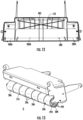
- FIG. 12 illustrates a view of the carriage 122 in an open configuration as seen with a top 278 ( FIG. 11 ) of the carriage 122 removed.
- an internal volume 280 of the carriage 122 is accessible.
- An operator can fill, or partially fill, the internal volume 280 with a fill material to selectively increase the weight of the towable element 114.
- Exemplary fill materials include water, sand, dirt, rocks, etc.
- the operator can add the fill material evenly within the internal volume 280 to generate a uniform weight profile across the entire towable element 114.
- the operator can add the fill material in a non-even distribution within the internal volume 280 to generate a desired weight profile.
- the internal volume 280 can include discrete portions such as a first portion 280A, a second portion 280B and a third portion 280C. Each portion can be separately weighted to form a desired weight profile.
- the internal volume 280 may include a drain or emptying port 282 which permits an operator to selectively unload the fill material from the internal volume 280. Alternatively, the operator can tilt the towable element 114 to expel material from the internal volume 280 or trowel the fill material from the internal volume 280 by hand.
- the work tool 154 can be swapped between a plurality of different work tools 154.
- the plurality of different work tools can include stripers, aerators, dethatchers, nut pickers, scarifiers, etc.
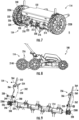
- FIGS. 13 to 15 illustrate a striper 284 acting as the work tool 154 in accordance with an embodiment.
- the striper 284 can generally include an elongated body 286 spanning the first and second attachment structures 202 and 204.
- the elongated body 286 can be a cylindrical wheel.
- the cylindrical wheel can include a hollow core 288 and an outer surface 290 which interfaces with the underlying ground surface G.
- Spokes 292 can extend radially outward from a central axle 294 to support the outer surface 290.
- the outer surface 290 and spokes 292 can be deformable to take up and absorb obstacles encountered by the striper 284.
- at least one of the outer surface 290 and spokes 292 can be rigid.
- the central axle 294 can interface with the first and second attachment structures 202 and 204, e.g., in a manner as described above.
- the striper 284 may not interface with the slots secondary interface, i.e., the slots 268.
- the elongated body 286 may passively rotate as the striper 284 is moved along an underlying ground surface G.
- the striper 284 can include a plurality of segments 296.
- the segments 296 can be stacked along the central axle 294 and retained thereon by a locking feature, such as a c-clamp 298.
- the c-clamp 298 can rest within a groove of the central axis 294 to retain the stacked segments 296 on the central axle 294.
- the segments 296 can be rotationally pinned relative to one another or freely moveable with respect to each other.
- the striper 284 can press against the ground surface G under the weight of the towable element 114 to create lawn striping.
- the towable element 114 can be weighted by filler material applied in the internal volume 280 to exert additional downward force through the striper 284 onto the underlying ground surface G.
- FIG. 16 illustrates an aerator 300 acting as the work tool 154 in accordance with an embodiment.
- the aerator 300 can generally include a shaft 302 and a plurality of aerating elements 304 coupled to the shaft 302.
- the aerating elements 304 each include a central member 306 interfaced with the shaft 302 and tines 308 projecting from the central member 306.
- the depicted embodiment illustrates four aerating elements 304 each including four tines 308, however it should be understood that the aerator 300 can include any number of aerating elements 304 including any number of tines 308.
- the tines 308 are all shown oriented at the same relative angle as one another, in other embodiments, the tines 308 can be rotationally offset from one another.
- the shaft 302 can passively rotate as the aerator 300 is moved along an underlying ground surface G.
- the tines 308 can penetrate into the underlying ground surface G under the weight of the towable element 114.
- the towable element 114 can be weighted by filler material applied in the internal volume 280 to exert additional downward force through the tines 308 into the underlying ground surface G.
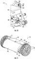
- FIG. 17 illustrates a nut picker 310 acting as the work tool 154 in accordance with an embodiment.
- the nut picker 310 can generally include a framework 312 configured to be coupled with the first and second attachment structures 202 and 204 and the secondary slot 268.
- An axle 314 is coupled to the framework 312 and defines a rotatable interface for a nut picking tool 316.
- the nut picking tool 316 can include a plurality of hubs 318 positioned adjacent to one another, each having a plurality of fingers 320 extending radially outward from the hubs 318.
- the fingers 320 can include enlarged heads 322 disposed at or adjacent to distal ends of the fingers 320.
- a comb 324 can extend into the fingers 320 to remove nuts and other accumulated materials therefrom.
- the comb 324 is part of the framework 312.
- the comb 324 can include a separate, discrete piece coupled to the carriage 122 or another portion of the towable element 114.
- the top 278 ( FIG. 11 ) of the carriage 122 can be removed and nuts can pass from the comb 324 to the internal volume 280.
- the internal volume 280 can serve as a temporary storage area for collected nuts.
- FIG. 18 illustrates the comb 324 as seen with teeth 326 of the comb 324 extending between adjacent fingers 320 of the nut picking tool 316.
- the teeth 326 can be sized, shaped and spaced apart so as to fit between adjacent hubs 318. In some instances, the teeth 326 can extend all the way to the outermost hubs 318. In other instances, the teeth 326 can extend a majority of the distance to the outermost hubs 318.
- FIGS. 19 and 20 illustrate combs 324A and 324B, respectively, in accordance with different embodiments.
- the comb 324A depicted in FIG. 19 has a single piece construction with teeth 326A integrated into a support bar 328A.
- the comb 324B depicted in FIG. 20 has a multiple piece construction with individual teeth 326B independently coupled together through a common support bar 328B.
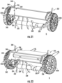
- FIGS. 21 and 22 illustrate a scarifier 330 acting as the work tool 154 in accordance with an embodiment.
- the scarifier 330 generally includes a plurality of scarifier blades 332 that rotate about an axis defined by a shaft 334.
- the scarifier 330 can include at least two scarifier blades 332, such as at least three scarifier blades 332, such as at least five scarifier blades 332.
- the scarifier blades 332 can each include a central hub 336 and one or more blade segments 338 extending from the central hub 336.
- the scarifier blades 332 can include two blade segments 338 extending from opposite sides of the central hub 336.
- the scarifier blades 332 can be rotationally pinned to the shaft 334, directly or indirectly, such that rotation of the shaft 334 causes the scarifier blades 332 to rotate.
- adjacent scarifier blades 332 can be rotationally staggered (offset) relative to one another.
- the scarifier blades 332 can form an offset whereby each scarifier blade 332 is rotationally offset from an adjacent scarifier blade 332 by the same relative rotational displacement, resulting in a wave motion when the scarifier blades 332 interface with the underlying ground surface G.
- the scarifier blades 332 can be separated from one another by spacers 339 which maintain the scarifier blades 332 at fixed distances relative to one another during rotation of the shaft 334.
- the scarifier 330 can include one or more gears 340 rotationally pinned relative to the shaft 334 such that rotational force imparted on the gear(s) 340 causes the shaft 334, and thus the scarifier blades 332, to rotate.
- rotation of the first and second wheels 232A and 232B drives the gears 340, causing the shaft 334 to rotate and thus driving the scarifier 330.
- the scarifier 330 can include an adjustment feature 342 that raises and lowers the scarifier 330 relative to the underlying ground surface G.
- the adjustment feature 342 can include any one or more similar feature as compared to the adjustment feature 242.
- the adjustment feature 342 can include an adjustment plate 344 including a plurality of stop positions, e.g., holes 346, which can each interface with a complementary feature of a user engageable member 348 to selectively retain the adjustment plate 344 at a fixed position, and thus maintain the scarifier 330 at a fixed height.
- the adjustment plate 344 can include a handle 350 to permit a user to more easily grasp the adjustment plate 344 when adjusting the height of the scarifier 330.
- the above-described adjustment feature 342 can be mirrored on the opposite side of the scarifier 330.
- the scarifier 330 can further include an adjustment feature 352 on an opposite side of the scarifier 330.
- the adjustment feature 352 can have any similar or different characteristics as compared to the adjustment feature 342.
- the operator may adjust the relative height of the scarifier 330 by adjusting only one of the adjustment features 342 or 352.
- the operator may be required to adjust both of the adjustment features 342 and 352 simultaneously to adjust the height of the scarifier 330.
- Embodiments described herein allow a lawnmower, or other moveable tool, access to additional functionality without compromising usability of the underlying lawnmower, or other moveable tool.
- a towable element can be coupled to the lawnmower and selectively receive a plurality of different work tools. By swapping between the different work tools, an operator can selectively adjust lawnmower functionality.
- Some work tools can operate passively whereby the work tool rotates as a result of the work tool directly interfacing with the ground during movement of the lawnmower. Passive work tools generally operate at a 1:1 speed relative to movement of the work tool over the underlying ground surface.
- a striper having an elongated body with a 25 centimeter (cm) circumference completes one revolution, or approximately one revolution, for every 25 cm of forward travel on the underlying ground surface.
- a striper having an elongated body with a 40 cm circumference completes one revolution, or approximately one revolution, for every 40 cm of travel on the underlying ground surface.
- Other work tools can operate actively whereby the work tool operates at an n: 1 speed relative to movement over the underlying ground surface, where n is greater than 1.
- dethatchers with a gear ratio of 50 operate at a 50:1 speed relative to the speed of the wheels.
- the dethatcher completes one revolution, or approximately one revolution, for every 1 cm of travel on the underlying ground surface, or 50 revolutions, or approximately 50 revolutions, for every 50 cm of travel on the underlying ground surface.
- This allows functionality associated with higher operating speeds (like dethatching and scarifying) without requiring a motor to drive the work tool and without requiring the operator to move the lawnmower at high speeds. While active functionality is described by way of example with respect to the dethatcher and scarifier, it should be understood that other work tools can operative actively.
Landscapes
- Life Sciences & Earth Sciences (AREA)
- Environmental Sciences (AREA)
- Engineering & Computer Science (AREA)
- Mechanical Engineering (AREA)
- Soil Sciences (AREA)
- Soil Working Implements (AREA)
Applications Claiming Priority (1)
| Application Number | Priority Date | Filing Date | Title |
|---|---|---|---|
| US202363537355P | 2023-09-08 | 2023-09-08 |
Publications (2)
| Publication Number | Publication Date |
|---|---|
| EP4520152A2 true EP4520152A2 (de) | 2025-03-12 |
| EP4520152A3 EP4520152A3 (de) | 2025-05-28 |
Family
ID=92632969
Family Applications (1)
| Application Number | Title | Priority Date | Filing Date |
|---|---|---|---|
| EP24197614.1A Pending EP4520152A3 (de) | 2023-09-08 | 2024-08-30 | Ziehbare elemente für rasenmäher und rasenmäher mit ziehbaren elementen |
Country Status (3)
| Country | Link |
|---|---|
| US (1) | US20250081890A1 (de) |
| EP (1) | EP4520152A3 (de) |
| AU (1) | AU2024219348A1 (de) |
Families Citing this family (1)
| Publication number | Priority date | Publication date | Assignee | Title |
|---|---|---|---|---|
| JP1751800S (ja) * | 2023-03-14 | 2023-08-29 | スカリファイヤ |
Family Cites Families (6)
| Publication number | Priority date | Publication date | Assignee | Title |
|---|---|---|---|---|
| US5163275A (en) * | 1990-06-01 | 1992-11-17 | Hare Ronald G | Pivoting handle mounting arrangement for lawn mower |
| US5870888A (en) * | 1997-05-12 | 1999-02-16 | Pugh; John F. | Lawn grooming and rolling accessories for lawn mowers |
| US7111443B2 (en) * | 2002-10-11 | 2006-09-26 | The Toro Copmany | Walk reel mower with electric drive and automatic slow down system |
| US7478681B2 (en) * | 2006-09-06 | 2009-01-20 | Alston Charles D | Lawn mower roller attachment |
| US20080202091A1 (en) * | 2007-02-22 | 2008-08-28 | Bundy G Douglas | Multi-purpose tool for attachment to a lawnmower |
| US8316628B2 (en) * | 2008-10-08 | 2012-11-27 | Humphrey John L | Grass treatment unit with adjustable hood and grass treatment insert |
-
2024
- 2024-08-30 EP EP24197614.1A patent/EP4520152A3/de active Pending
- 2024-09-03 AU AU2024219348A patent/AU2024219348A1/en active Pending
- 2024-09-04 US US18/823,918 patent/US20250081890A1/en active Pending
Also Published As
| Publication number | Publication date |
|---|---|
| AU2024219348A1 (en) | 2025-03-27 |
| EP4520152A3 (de) | 2025-05-28 |
| US20250081890A1 (en) | 2025-03-13 |
Similar Documents
| Publication | Publication Date | Title |
|---|---|---|
| EP2078113B1 (de) | Kombinationsgerät zum schneefräsen, mähen, vertikutieren, bodenhacken oder dgl. | |
| US8752855B2 (en) | Accessory mounting systems for non-highway vehicles | |
| US6241025B1 (en) | Aerator | |
| US8186135B2 (en) | Electrically-powered combination lawn mower, trimmer and edger | |
| US5628171A (en) | Mulching mower convertible to discharge/collection mode | |
| US11148176B2 (en) | Power sweeper | |
| US20250081890A1 (en) | Towable elements for lawnmowers and lawnmowers with towable elements | |
| JPH04229105A (ja) | 芝の縁取り装置、芝刈り機/芝縁取り装置および縁取りディスク | |
| US20100132229A1 (en) | Powered Implement Machine | |
| WO1990010754A1 (de) | Selbstfahrendes nutzfahrzeug für die strandreinigung | |
| US6334630B1 (en) | Device and method to prevent grass buildup on lawnmower wheels | |
| US20240114828A1 (en) | Mow deck and bagging system for high efficiency walk-behind mowing apparatus | |
| US20050023010A1 (en) | Counter-rotating twin shaft system for gardening machines | |
| US5134838A (en) | Mower pick-up broom | |
| WO2009140748A1 (pt) | Equipamento para corte, recolhimento e processamento dinâmico de grama | |
| US5408813A (en) | Dethatching apparatus with independently rotating sets of tines | |
| US7918077B2 (en) | Grass treatment devices | |
| WO2007009627A1 (de) | Vorrichtung zur säuberung, insbesondere zur sandentfernung, von grasflächen | |
| KR102350076B1 (ko) | 공압을 이용한 예초유닛과 이를 이용한 청소차 | |
| US20050252184A1 (en) | Reel | |
| US5062257A (en) | Mowing apparatus | |
| CN219876907U (zh) | 滚刷机构、滚刷装置及割草设备 | |
| US7845151B2 (en) | Apparatus preferably for horticulture and/or parks | |
| JP3033469U (ja) | 清掃作業車 | |
| AU2003302669B2 (en) | Reel |
Legal Events
| Date | Code | Title | Description |
|---|---|---|---|
| PUAI | Public reference made under article 153(3) epc to a published international application that has entered the european phase |
Free format text: ORIGINAL CODE: 0009012 |
|
| STAA | Information on the status of an ep patent application or granted ep patent |
Free format text: STATUS: THE APPLICATION HAS BEEN PUBLISHED |
|
| AK | Designated contracting states |
Kind code of ref document: A2 Designated state(s): AL AT BE BG CH CY CZ DE DK EE ES FI FR GB GR HR HU IE IS IT LI LT LU LV MC ME MK MT NL NO PL PT RO RS SE SI SK SM TR |
|
| PUAL | Search report despatched |
Free format text: ORIGINAL CODE: 0009013 |
|
| AK | Designated contracting states |
Kind code of ref document: A3 Designated state(s): AL AT BE BG CH CY CZ DE DK EE ES FI FR GB GR HR HU IE IS IT LI LT LU LV MC ME MK MT NL NO PL PT RO RS SE SI SK SM TR |
|
| RIC1 | Information provided on ipc code assigned before grant |
Ipc: A01B 45/02 20060101AFI20250423BHEP |
|
| STAA | Information on the status of an ep patent application or granted ep patent |
Free format text: STATUS: REQUEST FOR EXAMINATION WAS MADE |
|
| 17P | Request for examination filed |
Effective date: 20251128 |