EP4518110A2 - Motoranordnung - Google Patents
Motoranordnung Download PDFInfo
- Publication number
- EP4518110A2 EP4518110A2 EP24197537.4A EP24197537A EP4518110A2 EP 4518110 A2 EP4518110 A2 EP 4518110A2 EP 24197537 A EP24197537 A EP 24197537A EP 4518110 A2 EP4518110 A2 EP 4518110A2
- Authority
- EP
- European Patent Office
- Prior art keywords
- motor
- gear
- center
- annulus
- support frame
- Prior art date
- Legal status (The legal status is an assumption and is not a legal conclusion. Google has not performed a legal analysis and makes no representation as to the accuracy of the status listed.)
- Pending
Links
Images





Classifications
-
- H—ELECTRICITY
- H02—GENERATION; CONVERSION OR DISTRIBUTION OF ELECTRIC POWER
- H02K—DYNAMO-ELECTRIC MACHINES
- H02K7/00—Arrangements for handling mechanical energy structurally associated with dynamo-electric machines, e.g. structural association with mechanical driving motors or auxiliary dynamo-electric machines
- H02K7/10—Structural association with clutches, brakes, gears, pulleys or mechanical starters
- H02K7/116—Structural association with clutches, brakes, gears, pulleys or mechanical starters with gears
-
- F—MECHANICAL ENGINEERING; LIGHTING; HEATING; WEAPONS; BLASTING
- F16—ENGINEERING ELEMENTS AND UNITS; GENERAL MEASURES FOR PRODUCING AND MAINTAINING EFFECTIVE FUNCTIONING OF MACHINES OR INSTALLATIONS; THERMAL INSULATION IN GENERAL
- F16H—GEARING
- F16H1/00—Toothed gearings for conveying rotary motion
- F16H1/28—Toothed gearings for conveying rotary motion with gears having orbital motion
-
- F—MECHANICAL ENGINEERING; LIGHTING; HEATING; WEAPONS; BLASTING
- F16—ENGINEERING ELEMENTS AND UNITS; GENERAL MEASURES FOR PRODUCING AND MAINTAINING EFFECTIVE FUNCTIONING OF MACHINES OR INSTALLATIONS; THERMAL INSULATION IN GENERAL
- F16H—GEARING
- F16H55/00—Elements with teeth or friction surfaces for conveying motion; Worms, pulleys or sheaves for gearing mechanisms
- F16H55/02—Toothed members; Worms
- F16H55/06—Use of materials; Use of treatments of toothed members or worms to affect their intrinsic material properties
-
- H—ELECTRICITY
- H02—GENERATION; CONVERSION OR DISTRIBUTION OF ELECTRIC POWER
- H02K—DYNAMO-ELECTRIC MACHINES
- H02K1/00—Details of the magnetic circuit
- H02K1/06—Details of the magnetic circuit characterised by the shape, form or construction
- H02K1/12—Stationary parts of the magnetic circuit
- H02K1/18—Means for mounting or fastening magnetic stationary parts on to, or to, the stator structures
- H02K1/187—Means for mounting or fastening magnetic stationary parts on to, or to, the stator structures to inner stators
-
- H—ELECTRICITY
- H02—GENERATION; CONVERSION OR DISTRIBUTION OF ELECTRIC POWER
- H02K—DYNAMO-ELECTRIC MACHINES
- H02K16/00—Machines with more than one rotor or stator
Definitions
- the present technology relates to electric motor assemblies.
- Electric vehicle production is increasing, with vehicles of many types being designed or adapted to be electrically powered, including for transport and recreation.
- the electric powertrain for many different vehicles could thus requires a motor specifically designed for that application.
- Development and testing may be elaborate, both incurring cost and time before the vehicle can be brought to market.
- an electric motor assembly combining electric motors with a particular planetary drive to provide an electrically powered drive shaft with a very flexible torque and speed output.
- a set of planetary gears, supported by a carrier connects sun gear and ring gear, with the planet gear carrier providing an output shaft. In this configuration, depending on the speed and direction of rotation of the individual motors, their power or torque can be added (with some limitations).
- the motors are outrunner motors, i.e. with the rotor on the outside.
- the motor gears can be press-fit or otherwise mounted on the outside and the motors are therefore disposed inside the planetary gear assembly, thus providing a compact assembly.
- this arrangement provides a low pressure between teeth of the different gears, allowing the gears to be formed of plastic in at least some embodiments.
- a motor assembly including an annulus gear including an annulus gear body having a hollow cylindrical form, and a plurality of annulus gear teeth disposed on an inner surface of the annulus gear body, the annulus gear rotating about a center rotation axis; at least one first motor disposed in an interior of the annulus gear, the at least one first motor being an outrunner electric motor rotating about a first motor axis, the first motor axis being parallel to the center rotation axis, the at least one first motor being arranged to drive the annulus gear; a carrier disposed at least partially in the interior of the annulus gear.
- the carrier includes a carrier body defining an output shaft, and a plurality of carrier gears rotationally connected to the carrier body, gear teeth of the plurality of carrier gears being engaged with the plurality of annulus gear teeth; a center gear disposed in the interior of the annulus gear, the center gear including a center gear body, and a plurality of center gear teeth disposed on an outer surface of the center gear body, a rotation axis of the center gear being coaxial with the center rotation axis, the gear teeth of the plurality of carrier gears being engaged with the plurality of center gear teeth; and at least one second motor disposed in the interior of the annulus gear, the at least one second motor being an outrunner electric motor rotating about a second motor axis, the second motor axis being parallel to the center rotation axis, the at least one second motor being arranged to drive the center gear.
- an outer surface of the at least one first motor having a plurality of first gear teeth, the plurality of first gear teeth being engaged with the plurality of annulus gear teeth; and an outer surface of the at least one second motor having a plurality of second gear teeth, the plurality of second gear teeth being engaged with plurality of center gear teeth.
- rotation of the at least one first motor causes rotation of the annulus gear; and rotation of the at least one second motor causes rotation of the center gear.
- the at least one first motor includes a first ring motor engaged with the annulus gear; and a second ring motor engaged with the annulus gear.
- the first ring motor and the second ring motor are oppositely disposed about the center gear.
- the at least one second motor includes a first hub motor engaged with the center gear; and a second hub motor engaged with the center gear.
- the first ring motor, the second ring motor, the first hub motor, and the second hub motor are disposed around the center gear.
- the first ring motor is disposed angularly between the first hub motor and the second hub motor; and the second ring motor is disposed angularly between the second hub motor and the first hub motor.
- the motor assembly further includes a support frame; and the annulus gear is arranged to freely rotate relative to the support frame, and a center position of the at least one first motor and a center position the at least one second motor is fixed relative to the support frame.
- the annulus gear is surrounded by the support frame; and the output shaft of the carrier extends through and out of the support frame.
- the support frame includes a bearing, the output shaft extending through and being supported by the bearing.
- the stator shaft of the at least one first motor extends through at least one first opening in the support frame, the support frame preventing movement of the center position of the at least one first motor at least in part by contact of the stator shaft with the at least one first opening; and the stator shaft of the at least one second motor extends through at least one second opening in the support frame, the support frame preventing movement of the center position of the at least one second motor at least in part by contact of the stator shaft with the at least one second opening.
- the plurality of first gear teeth is formed from plastic; and the plurality of second gear teeth is formed from plastic.
- the at least one first motor is a plurality of ring motors engaged with the annulus gear; and the at least one second motor is a plurality of hub motors engaged with the center gear.
- Embodiments of the present technology each have at least one of the above-mentioned aspects, but do not necessarily have all of them.
- motor assembly 100 The present technology of a motor assembly 100 is generally described herein for use in vehicles, including but not limited to recreational vehicles such as motorcycles, scooters, karts, snowmobiles, and off-road vehicles. It is also contemplated that the motor assembly 100, at least in some embodiments, could be configured and arranged to drive other apparatuses, such as power equipment, including but not limited to heavy machinery, pumps, and lawnmowers.
- the motor assembly 100 includes electric outrunner motors and an epicyclic gear drive.
- the outrunner motors are located within the gear drive to increase contact between the motors and their corresponding gears and decrease an overall volume of the system.
- the epicyclic gear drive combines the speed and torque of the motors, providing a flexible powering arrangement suitable for a variety of different electric gear trains.
- the motor assembly 100 could thus be used in many different vehicles and/or apparatuses.
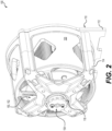
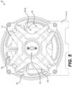
- the motor assembly 100 also referred to as the assembly 100, includes a support frame 110 for supporting the motor and gear components disposed therein, also referred to as a subassembly 102 (described below) of the assembly 100.
- the frame 110 is configured to connected to motor mounts (not shown) when installed in a vehicle or other apparatus.
- the support frame 110 includes a faceplate 112 and a cage 114 connected thereto.
- the cage 114 includes a bearing 116 for supporting an output shaft 154.
- the frame could be formed by a larger structure, such as part of a vehicle frame or a swing arm of a motorcycle or three-wheeled straddle seat vehicle.
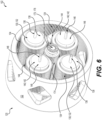
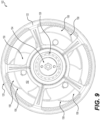
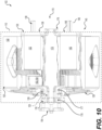
- the subassembly 102 broadly the components of the assembly 100 that are supported by the support frame 110, is additionally illustrated in Figures 6 to 10 .
- the assembly 100/subassembly 102 includes an exterior gear 120, commonly referred to as an annulus gear 120, disposed between the faceplate 112 and the cage 114.
- the annulus gear 120 includes an annulus gear body 122 with a hollow cylindrical form, further illustrated in Figure 11 .
- the annulus gear 120 includes a plurality of annulus gear teeth 124 disposed on an inner surface of the annulus gear body 120 for engaging with other gears of the assembly 100 (described below).
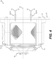
- the annulus gear 120 further includes a rear support structure 126 and a bearing 128 connected to the rear support structure 126 (use thereof is described below). When in use, the annulus gear 120 rotates about a center rotation axis 101 (see Figure 4 ) of the assembly 100.
- the assembly 100 includes one or more electric motors 130 for driving rotation of the annulus gear 120, referred to herein as ring motors 130.
- ring motors 130 are disposed in an interior of the annulus gear 120 and the support frame 110. It is contemplated that in some embodiments, only one ring motor 130 may be included. It is also contemplated that more than two motors 130 could be included.
- the ring motors 130 are specifically two outrunner electric motors 130.
- a main body 132 of each motor 130 houses the operational components thereof, with an outer surface having a plurality of gear teeth 134.
- the teeth 134 are disposed on an exterior of the rotor (not separately illustrated) which rotates about a fixed stator (not shown) having a cover plate 138 and a central passage; the rotor being connected to a rotor shaft 136 extending through the central passage.
- the teeth 134 are formed by a cylindrical plastic gear press-fit around the motor body 132, although it is contemplated that the teeth 134 of each motor 130 could be differently formed. It is also contemplated that the shafts 136 could be omitted in some embodiments.
- the faceplate 112 of the support frame 110 has defined therein openings, specifically shaft apertures 115 in the faceplate 112, for receiving the rotor shafts 136 therethrough.
- the stators are fixed to the faceplate 112 by fasteners, such as bolts (not shown) extending through openings 111 in the faceplate 112 and connecting to the cover plate 138 such that the rotor shafts 136 extend through the apertures 115.
- the shaft apertures 115 may also be omitted.
- the faceplate 112 also includes a plurality of apertures defined therein for receiving therethrough wires (not shown) of the motors 130 for communicatively and electrically connecting the motors 130 to a power source (not shown) and one or more controllers (not shown) for powering and controlling operation of the motors 130.
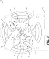
- the exterior-disposed gear teeth 134 rotate about a motor axis 131 defined through a center of the shaft 136 (see Figures 3 and 4 ), with the center position of each motor 130 being fixed relative to the support frame 110 as noted above.
- the motors 130 are positioned and arranged to drive the annulus gear 120, with the gear teeth 134 being engaged with the annulus gear teeth 124.
- the assembly 100/subassembly 102 also includes a center gear 170 disposed in the interior of the annulus gear 120. Commonly referred to as a sun gear, the center gear 170 is disposed at a center of the annulus gear 120.
- the center gear 170 has a center gear body 172 rotationally supported by the support frame 110 and a carrier 150 of the assembly 100 (described below).
- a plurality of center gear teeth 174 are disposed on an outer surface of the center gear body 172 for engaging with other components of the assembly 100.
- An axis of rotation (not separately labeled) of the center gear 170 is coaxial with the center rotation axis 101.
- the center gear 170 also includes a front bearing 176 (see Figures 10 , 11 ) operatively connected to the center gear body 172 for rotationally connecting to the faceplate 112.
- the faceplate 112 has a center aperture 113 for supporting the center gear 170.
- the front bearing 176 is disposed in the center aperture 113 for rotationally supporting a front end portion of the center gear 170, with the center gear 170 freely rotating relative to the faceplate 112.
- the center gear 170 further includes two rear bearings 177, 178 operatively connected to the center gear body 172 for rotationally supporting a rear end portion of the center gear 170, described in more detail below.
- the center gear 170 could include only one rear bearing or be arranged with a different support structure.
- the assembly 100/subassembly 102 further includes one or more electric motors 140 for driving rotation of the center gear 170, referred to herein as hub motors 140 or sun motors 140.
- hub motors 140 for driving rotation of the center gear 170
- sun motors 140 two hub motors 140 are disposed in an interior of the annulus gear 120 and the support frame 110. It is contemplated that in some embodiments, only one hub motor 140 could be included. It is also contemplated that more than two hub motors 140 could be included.
- the two hub motors 140 are specifically two outrunner electric motors 140.
- a main body 142 of each motor 140 houses the operational components thereof, with an outer surface having a plurality of gear teeth 144.
- the teeth 144 are disposed on an exterior of the rotor (not separately illustrated) which rotates about a fixed stator (not shown) having a cover plate 148 and a central passage; the rotor being connected to a rotor shaft 146 extending through the central passage.
- the teeth 144 are formed by a cylindrical plastic gear press-fit around the motor body 142, although it is contemplated that the teeth 144 of each motor 140 could be differently formed. It is also contemplated that the shafts 146 could be omitted in some embodiments.
- the stators are fixed to the faceplate 112 by fasteners, such as bolts (not shown) extending through openings 111 in the faceplate 112 and connecting to the cover plate 148 such that the rotor shafts 146 extend through the apertures 115.
- the apertures 115 may also be omitted.
- the faceplate 112 also includes a plurality of apertures defined therein for receiving therethrough wires (not shown) of the motors 140 for communicatively and electrically connecting the motors 140 to a power source (not shown) and one or more controllers (not shown) for powering and controlling operation of the motors 140. It is also contemplated that one or more controllers could be disposed within the frame 110, in spaces between the motors 130, 140.
- the exterior-disposed gear teeth 144 rotate about a motor axis 141 defined through a center of the shaft 146 (see Figures 3 and 4 ), with the center position of each motor 140 being fixed relative to the support frame 110 as noted above.
- the motors 140 are positioned and arranged to drive the center gear 170, with the gear teeth 144 being engaged with the center gear teeth 174.
- the relative arrangement of the ring motors 130 and the hub motors 140 is illustrated.
- the ring motors 130 and the hub motors 140 are disposed around the center gear 170, with the rotation axis 131, 141 of each motor 130, 140 being positioned parallel to the center rotation axis 101 (see also Figure 4 ).
- the motors 130, 140 are arranged in an alternation sequence; specifically each ring motor 130 is disposed between the two hub motors 140 angularly about the center axis 101 and vice versa.
- the ring motors 130 are thus oppositely disposed about the center gear 170.
- the hub motors 140 are similarly oppositely disposed about the center gear 170. It is contemplated that the specific placement of the motors 130, 140 could vary in different embodiments.
- the assembly 100 further includes a carrier 150 for converting and combining motion from the motors 130, 140, via the annulus gear 120 and the center gear 170.
- the carrier 150 includes a carrier body 152 defining the output shaft 154, the output shaft 154 being configured and arranged for operatively connecting to a drivetrain of the vehicle in which the motor assembly 100 is installed.
- a main portion of the carrier body 152 is disposed in the interior of the annulus gear 120 and inside the support frame 110.
- the output shaft 154 extends from the interior of the annulus gear 120, through the bearing 128 in the rear support structure 126, through the bearing 116 of the cage 114, and out of the support frame 110.
- more of the carrier 150 could be disposed on an exterior of the annulus gear 120.
- the particular arrangement of the carrier 150 and the annulus gear 120 is contemplated to vary depending on the specific embodiment.
- the carrier 150 includes a plurality of carrier gears 156 rotationally connected to the carrier body 152.
- the carrier 150 includes three carrier gears 156. It is contemplated that the carrier 150 could include more or fewer gears in different embodiments.
- the carrier gears 156 each include a plurality of gear teeth 158 for operatively connecting the carrier 150 to the annulus gear 120 and the center gear 170. As is further illustrated in Figure 12 , the carrier gear teeth 158 are engaged with the center gear teeth 174 and the annulus gear teeth 124.
- the subassembly 102 is rotationally supported by the support frame 110 (shown schematically in Figure 10 ), such that the annulus gear 120, the carrier 150, and the center gear 170 are arranged to freely rotate relative to the support frame 110.
- the output shaft 154, and thus the carrier 150 is supported by the cage 114 of the support frame 110 via the bearing 116.
- a front portion of the center gear 170 is supported by the faceplate 112 via the bearing 174 of the center gear 170.
- the center of the subassembly 102 is thus supported by, but freely rotates relative to, the support frame 110.
- the annulus gear 120 is supported in turn via the bearing 128 rotatively connecting the annulus gear 120 to the carrier body 154.
- the motion and speed of the motors 130, 140 can be combined to produce a wide variety of output torques and speeds at the output shaft 154.
- rotation of the ring motors 130 causes rotation of the annulus gear 120 and rotation of the hub motors 140 causes rotation of the center gear 170.
- Rotation of the annulus gear 120 and the center gear 170 in turn drives rotation of the carrier 150 through engagement of the carrier gears 156 therewith, in combination with the free rotation of the carrier 150 relative to the support frame 110.
- the speed and direction of rotation of the carrier 150, and thus the output shaft 154 in the present technology depends on the speed and direction of the motors 130, 140. While the two ring motors 130 need to turn in a same direction, and similarly the two hub motors 140 must turn in a same direction, it is noted that the ring motors 130 could rotate in a direction opposite to the hub motors 140.
Landscapes
- Engineering & Computer Science (AREA)
- General Engineering & Computer Science (AREA)
- Mechanical Engineering (AREA)
- Power Engineering (AREA)
- Physics & Mathematics (AREA)
- Electromagnetism (AREA)
- Thermal Sciences (AREA)
- Connection Of Motors, Electrical Generators, Mechanical Devices, And The Like (AREA)
- General Details Of Gearings (AREA)
Applications Claiming Priority (1)
| Application Number | Priority Date | Filing Date | Title |
|---|---|---|---|
| US202363535706P | 2023-08-31 | 2023-08-31 |
Publications (2)
| Publication Number | Publication Date |
|---|---|
| EP4518110A2 true EP4518110A2 (de) | 2025-03-05 |
| EP4518110A3 EP4518110A3 (de) | 2025-04-02 |
Family
ID=92633031
Family Applications (1)
| Application Number | Title | Priority Date | Filing Date |
|---|---|---|---|
| EP24197537.4A Pending EP4518110A3 (de) | 2023-08-31 | 2024-08-30 | Motoranordnung |
Country Status (3)
| Country | Link |
|---|---|
| US (1) | US12289033B2 (de) |
| EP (1) | EP4518110A3 (de) |
| CA (1) | CA3253576A1 (de) |
Family Cites Families (8)
| Publication number | Priority date | Publication date | Assignee | Title |
|---|---|---|---|---|
| US4691119A (en) | 1985-06-20 | 1987-09-01 | Westinghouse Electric Corp. | Permanent magnet alternator power generation system |
| JP3626151B2 (ja) * | 2002-06-17 | 2005-03-02 | 日産自動車株式会社 | ハイブリッド変速機 |
| ES2364114B1 (es) | 2009-10-30 | 2012-07-04 | Antonio Luis Coloma Llinares | Mecanismo propulsor eléctrico de rotores múltiples. |
| EP3104503B1 (de) * | 2015-06-08 | 2018-03-28 | WMH Herion Antriebstechnik GmbH | Spielfreier drehantrieb |
| IT201800005221A1 (it) | 2018-05-09 | 2019-11-09 | Dispositivo per la trasmissione del moto | |
| DE102019203854B4 (de) | 2019-03-21 | 2025-03-27 | Universität Stuttgart | Antriebseinheit mit zusätzlich angetriebenem Planetengetriebe |
| CN113811703A (zh) * | 2019-04-01 | 2021-12-17 | 詹尼斯高级技术有限公司 | 齿轮箱 |
| US11673463B2 (en) * | 2021-01-07 | 2023-06-13 | Dana Heavy Vehicle Systems Group, Llc | Electric motor system |
-
2024
- 2024-08-29 CA CA3253576A patent/CA3253576A1/en active Pending
- 2024-08-29 US US18/818,772 patent/US12289033B2/en active Active
- 2024-08-30 EP EP24197537.4A patent/EP4518110A3/de active Pending
Also Published As
| Publication number | Publication date |
|---|---|
| CA3253576A1 (en) | 2025-06-03 |
| US12289033B2 (en) | 2025-04-29 |
| EP4518110A3 (de) | 2025-04-02 |
| US20250079934A1 (en) | 2025-03-06 |
Similar Documents
| Publication | Publication Date | Title |
|---|---|---|
| US7458433B2 (en) | Electric motor and gear drive assembly for driving a vehicle wheel | |
| US8771123B2 (en) | Reversible planetary gear assembly | |
| US6974399B2 (en) | Hub motor mechanism | |
| US8033943B2 (en) | In-wheel motor driving unit | |
| KR20070108863A (ko) | 높은 감속비의 전기 허브드라이브 | |
| JP2006112474A (ja) | 差動装置およびこれを用いた車両の駆動力伝達ユニット | |
| EP2711286B1 (de) | Antriebsstruktur für elektrische Fahrräder | |
| US11376952B1 (en) | In-wheel driving device and method for assembling the same | |
| CN109398079A (zh) | 具有电动马达模块的车桥组件 | |
| CN107962943A (zh) | 用于驱动电轴的驱动设备 | |
| KR20140131522A (ko) | 전기적으로 구동되는 차량 구동축 장치 | |
| CN102874096B (zh) | 轮毂驱动装置 | |
| JP3646084B2 (ja) | 車両の駆動装置 | |
| US12289033B2 (en) | Motor assembly | |
| KR20100023217A (ko) | 휠 직접 구동 장치 | |
| EP1461222B1 (de) | Elektrischer motor mit an das zu drehende element gekoppeltem rotor | |
| EP3738809B1 (de) | Kraftfahrzeug-getriebe und kraftfahrzeug-achse mit einem solchen getriebe | |
| KR101219894B1 (ko) | 차량의 리어액슬 | |
| WO2007043514A1 (ja) | 動力出力装置 | |
| US20240141980A1 (en) | Motor shaft with an internal axle differentiating capability | |
| JP2007078174A (ja) | 動力伝達装置 | |
| CN217607642U (zh) | 摆线内齿与机壳一体式无刷汽车转向电机 | |
| CN117685341A (zh) | 一种分动器执行机构及车辆 | |
| CN110203057A (zh) | 一种电动机驱动总成及一种车辆 | |
| US20210140515A1 (en) | Speed reducing unit |
Legal Events
| Date | Code | Title | Description |
|---|---|---|---|
| PUAI | Public reference made under article 153(3) epc to a published international application that has entered the european phase |
Free format text: ORIGINAL CODE: 0009012 |
|
| STAA | Information on the status of an ep patent application or granted ep patent |
Free format text: STATUS: THE APPLICATION HAS BEEN PUBLISHED |
|
| PUAL | Search report despatched |
Free format text: ORIGINAL CODE: 0009013 |
|
| AK | Designated contracting states |
Kind code of ref document: A2 Designated state(s): AL AT BE BG CH CY CZ DE DK EE ES FI FR GB GR HR HU IE IS IT LI LT LU LV MC ME MK MT NL NO PL PT RO RS SE SI SK SM TR |
|
| AK | Designated contracting states |
Kind code of ref document: A3 Designated state(s): AL AT BE BG CH CY CZ DE DK EE ES FI FR GB GR HR HU IE IS IT LI LT LU LV MC ME MK MT NL NO PL PT RO RS SE SI SK SM TR |
|
| RIC1 | Information provided on ipc code assigned before grant |
Ipc: H02K 1/18 20060101ALN20250224BHEP Ipc: H02K 16/00 20060101ALI20250224BHEP Ipc: H02K 7/116 20060101AFI20250224BHEP |
|
| STAA | Information on the status of an ep patent application or granted ep patent |
Free format text: STATUS: REQUEST FOR EXAMINATION WAS MADE |
|
| 17P | Request for examination filed |
Effective date: 20251002 |