EP4517235A1 - Cooling appliance with an item access unit - Google Patents
Cooling appliance with an item access unit Download PDFInfo
- Publication number
- EP4517235A1 EP4517235A1 EP23193621.2A EP23193621A EP4517235A1 EP 4517235 A1 EP4517235 A1 EP 4517235A1 EP 23193621 A EP23193621 A EP 23193621A EP 4517235 A1 EP4517235 A1 EP 4517235A1
- Authority
- EP
- European Patent Office
- Prior art keywords
- cooling appliance
- item
- interior
- cooling
- appliance
- Prior art date
- Legal status (The legal status is an assumption and is not a legal conclusion. Google has not performed a legal analysis and makes no representation as to the accuracy of the status listed.)
- Pending
Links
Images



Classifications
-
- F—MECHANICAL ENGINEERING; LIGHTING; HEATING; WEAPONS; BLASTING
- F25—REFRIGERATION OR COOLING; COMBINED HEATING AND REFRIGERATION SYSTEMS; HEAT PUMP SYSTEMS; MANUFACTURE OR STORAGE OF ICE; LIQUEFACTION SOLIDIFICATION OF GASES
- F25D—REFRIGERATORS; COLD ROOMS; ICE-BOXES; COOLING OR FREEZING APPARATUS NOT OTHERWISE PROVIDED FOR
- F25D25/00—Charging, supporting, and discharging the articles to be cooled
- F25D25/04—Charging, supporting, and discharging the articles to be cooled by conveyors
-
- F—MECHANICAL ENGINEERING; LIGHTING; HEATING; WEAPONS; BLASTING
- F25—REFRIGERATION OR COOLING; COMBINED HEATING AND REFRIGERATION SYSTEMS; HEAT PUMP SYSTEMS; MANUFACTURE OR STORAGE OF ICE; LIQUEFACTION SOLIDIFICATION OF GASES
- F25D—REFRIGERATORS; COLD ROOMS; ICE-BOXES; COOLING OR FREEZING APPARATUS NOT OTHERWISE PROVIDED FOR
- F25D23/00—General constructional features
- F25D23/10—Arrangements for mounting in particular locations, e.g. for built-in type, for corner type
-
- F—MECHANICAL ENGINEERING; LIGHTING; HEATING; WEAPONS; BLASTING
- F25—REFRIGERATION OR COOLING; COMBINED HEATING AND REFRIGERATION SYSTEMS; HEAT PUMP SYSTEMS; MANUFACTURE OR STORAGE OF ICE; LIQUEFACTION SOLIDIFICATION OF GASES
- F25D—REFRIGERATORS; COLD ROOMS; ICE-BOXES; COOLING OR FREEZING APPARATUS NOT OTHERWISE PROVIDED FOR
- F25D2400/00—General features of, or devices for refrigerators, cold rooms, ice-boxes, or for cooling or freezing apparatus not covered by any other subclass
- F25D2400/10—Refrigerator top-coolers
-
- F—MECHANICAL ENGINEERING; LIGHTING; HEATING; WEAPONS; BLASTING
- F25—REFRIGERATION OR COOLING; COMBINED HEATING AND REFRIGERATION SYSTEMS; HEAT PUMP SYSTEMS; MANUFACTURE OR STORAGE OF ICE; LIQUEFACTION SOLIDIFICATION OF GASES
- F25D—REFRIGERATORS; COLD ROOMS; ICE-BOXES; COOLING OR FREEZING APPARATUS NOT OTHERWISE PROVIDED FOR
- F25D2500/00—Problems to be solved
- F25D2500/06—Stock management
-
- F—MECHANICAL ENGINEERING; LIGHTING; HEATING; WEAPONS; BLASTING
- F25—REFRIGERATION OR COOLING; COMBINED HEATING AND REFRIGERATION SYSTEMS; HEAT PUMP SYSTEMS; MANUFACTURE OR STORAGE OF ICE; LIQUEFACTION SOLIDIFICATION OF GASES
- F25D—REFRIGERATORS; COLD ROOMS; ICE-BOXES; COOLING OR FREEZING APPARATUS NOT OTHERWISE PROVIDED FOR
- F25D31/00—Other cooling or freezing apparatus
- F25D31/006—Other cooling or freezing apparatus specially adapted for cooling receptacles, e.g. tanks
- F25D31/007—Bottles or cans
Definitions
- the interior of the cooling appliance typically exhibits a certain height between the bottom wall and the top wall of the housing of the cooling appliance.
- the top region of the interior of the cooling appliance may start at the top wall of the housing of the cooling appliance and may be limited to a distance from the top wall of the housing of the cooling appliance of 20% or less of the height.
- the cooling appliance comprises an item access unit which is located within the interior of the cooling appliance, which comprises a plurality of different item holders and which is configured to move a selected one of the plurality of item holders into the top region of the interior of the cooling appliance, such that a user of the cooling appliance is enabled to access the selected item holder via the opening lid.
- the item holders may be trays onto which one or more items, in particular food items, may be placed.
- a cooling appliance which provides locally constrained access to the cooled interior of the housing of the cooling appliance only via the top region of the cooling appliance.
- the cooling appliance comprises an item access unit which is configured to selectively place different item holders (notably trays) within the top region.
- an energy efficient and comfortable access to the different items within the interior of the cooling appliance may be provided.
- conventional cooling appliances may be less energy efficient because every time somebody opens the front door the cold air flows out of the cooling appliance (as it has a higher density than warm air) and warmer air streams into the cooling appliance, which needs to be cooled down again after the access to the stored food items.
- the item access unit may comprise a conveyor belt, especially a vertical conveyor belt.
- the main axis of the conveyor belt may be oriented vertically.
- the item access unit may comprise a drive pulley and a tail pulley, which are configured to move the conveyor belt.
- the drive pulley and the tail pulley may be aligned along a vertical line (which is vertical with respect to the floor that the cooling appliance is placed on).
- the conveyor belt may have a certain length along the vertical direction, which is dependent on the height of the housing of the cooling appliance.
- the length along the vertical direction is typically 5 times or more, or 10 times or more, larger than the (horizontal) diameter of the pulleys.
- the plurality of item holders may be attached to a corresponding plurality of attachment points of the conveyor belt.
- the item holders of the plurality of item holders may each be attached to the conveyor belt using a hinge.
- the hinges may ensure that the individual item holders which are attached to the conveyor belt are each maintained horizontally during a complete revolution of the respective item holder. By doing this, items may be placed in a secure manner onto the different item holders.
- the plurality of item holders may e.g., comprise 5 or more, or 10 or more item holders.
- the item holders may be arranged in a distributed manner along the conveyor belt.
- the item holders may be uniformly spaced from one another along the longitudinal extension of the conveyor belt.
- the cooling appliance may comprise a fixing mechanism which is configured to selectively hold the item holder which is positioned in the top region of the interior of the cooling appliance in a defined and stable position. By doing this, the comfort-of-use of the cooling appliance may be further increased. Especially, it may be avoided that food items fall down because of a wobbly item holder during the access procedure.
- the item access unit may comprise one or more additional stationary item holders which are positioned between the drive pulley and the tail pulley and which are surrounded by the conveyor belt.
- the cooling appliance may comprise a front door at the front side of the housing of the cooling appliance.
- the front door may be configured to provide access to a region at the front side of the interior of the cooling appliance, which spans from the bottom wall to the top wall of the housing of the cooling appliance.
- the cooling appliance typically comprises a user interface, which is configured to allow the user to select an item, which is to be accessed through the opening lid.
- the user interface may be enabled for natural language processing, thereby providing a particularly comfortable user interaction.
- the cooling appliance may comprise a sensor, in particular a camera, which is configured to capture sensor data regarding items placed within the item access unit. Furthermore, the cooling appliance may comprise a control unit, which is configured to identify the items placed within the item access unit based on the sensor data. This identification may be performed e.g. by an artificial neural networks, which has been trained to be able to recognize food items.
- the cooling appliance may comprise a dedicated object recognition region, in which a plurality of cameras are located, which observe an item holder passing by preferably from different angles.
- a dedicated object recognition region in which a plurality of cameras are located, which observe an item holder passing by preferably from different angles.
- the images taken by the plurality of cameras may be combined to recognize the item. In comparison to conventional cooling appliances this may allow for a higher object recognition rate.
- the control unit may be configured to determine for an, in particular for each, identified item the item holder of the plurality of item holders that the identified item is placed on. By doing this, a stock list of the items which are placed within the item access unit and of the item holders that the respective items are placed on may be managed in an efficient and reliable manner.
- the control unit may be configured to determine, in particular via the user interface of the cooling appliance, a particular item that the user of the cooling appliance wants to access. Based on the managed stock list, the item access unit may be caused to move the item holder that the particular item is placed on into the top region of the interior of the cooling appliance. Furthermore, it may be indicated to the user via the user interface that the particular item is ready for access at the top region of the interior of the cooling appliance. As a result of this, a particularly energy efficient and comfortable access to individual items may be provided.
- the technology described in this disclosure may provide an optimized cooling appliance for accessing stored food items by voice.
- a user may e.g. simply say to the cooling appliance: "Hey fridge, pass me the butter” and the cooling appliance will provide the butter at a predetermined position. This may be especially convenient for visually impaired persons or while working through a recipe when cooking.
- the speech recognition may be performed by the cooling appliance itself (possibly with the aid of a backend server) and/or by being connected to a smart speaker like the Smart Kitchen Dock of Bosch.
- the cooling appliance preferably comprises a communication module, which could be based e.g. on Wi-Fi and/or Bluetooth.
- cooling appliance In comparison to a conventional cooling appliance, no gripper arm is needed to pass a food item to the user. Moreover, object recognition in conventional cooling appliances may be difficult as many food items are located in front of other food items, which then are difficult to recognize.
- the cooling appliance described in this disclosure may allow for a much higher object recognition rate because food items may be easier to observe from multiple angles, e.g. due to the continuous and/or stepless movement of the conveyor belt and/or due to the above described dedicated object recognition region.
Landscapes
- Engineering & Computer Science (AREA)
- Chemical & Material Sciences (AREA)
- Combustion & Propulsion (AREA)
- Physics & Mathematics (AREA)
- Mechanical Engineering (AREA)
- Thermal Sciences (AREA)
- General Engineering & Computer Science (AREA)
- Devices That Are Associated With Refrigeration Equipment (AREA)
Abstract
A cooling appliance (100) for a kitchen of a household is described. The cooling appliance (100) comprises an opening lid (103) which is configured to provide access to the interior (105) of the cooling appliance (100), such that the access is limited to a top region of the interior (105) of the cooling appliance (100). Furthermore, the cooling appliance (100) comprises an item access unit (200) which is located within the interior (105) of the cooling appliance (100), which comprises a plurality of different item holders (201) and which is configured to move a selected one of the plurality of item holders (201) into the top region of the interior (105) of the cooling appliance (100), such that a user is enabled to access the selected item holder (201) via the opening lid (103).
Description
- The present document relates to a cooling appliance, such as a refrigerator or a freezer. In particular, the present document relates to providing access to different items within a cooling appliance in a comfortable and energy efficient manner.
- Within a household one or more cooling appliances, such as a refrigerator and/or a freezer, may be used for cooling different items, notably food items. The present document addresses the technical problem of energy efficiency and comfort-of-use of such a cooling appliance. The technical problem is solved by the independent claim. Preferred examples are described in the dependent claims.
- According to an aspect, a cooling appliance (in particular a refrigerator) for a kitchen of a household is described. The cooling appliance may be configured to be integrated within the worktop of a kitchen, in particular such that the opening lid (which is also referred to herein as an access hatch) of the cooling appliance is aligned with the worktop. The cooling appliance typically comprises a (cuboid shaped) housing. Furthermore, the cooling appliance is typically configured to cool the interior of the housing (e.g., to a temperature of 10° Celsius or less). The housing may comprise a bottom wall (which is facing the floor that the cooling appliance is placed on) and a top wall (which is opposite to the bottom wall and which may be aligned with the worktop). Furthermore, the housing may comprise side walls, in particular a side wall at the front side, which is facing a user of the cooling appliance. The side walls span from the bottom wall to the top wall of the housing.
- The cooling appliance comprises an opening lid (also referred to as an access hatch) which is configured to provide access to the interior of the cooling appliance, such that the access is limited to the top region of the interior of the cooling appliance. The opening lid may be located at the upper (i.e., top) housing wall of the housing of the cooling appliance, wherein the upper (i.e., top) housing wall and/or the opening lid typically have a horizontal orientation.
- The interior of the cooling appliance typically exhibits a certain height between the bottom wall and the top wall of the housing of the cooling appliance. The top region of the interior of the cooling appliance may start at the top wall of the housing of the cooling appliance and may be limited to a distance from the top wall of the housing of the cooling appliance of 20% or less of the height.
- Furthermore, the cooling appliance comprises an item access unit which is located within the interior of the cooling appliance, which comprises a plurality of different item holders and which is configured to move a selected one of the plurality of item holders into the top region of the interior of the cooling appliance, such that a user of the cooling appliance is enabled to access the selected item holder via the opening lid. Some or all of the item holders may be trays onto which one or more items, in particular food items, may be placed.
- Hence, a cooling appliance is described which provides locally constrained access to the cooled interior of the housing of the cooling appliance only via the top region of the cooling appliance. Furthermore, the cooling appliance comprises an item access unit which is configured to selectively place different item holders (notably trays) within the top region. By doing this, an energy efficient and comfortable access to the different items within the interior of the cooling appliance may be provided. In comparison, conventional cooling appliances may be less energy efficient because every time somebody opens the front door the cold air flows out of the cooling appliance (as it has a higher density than warm air) and warmer air streams into the cooling appliance, which needs to be cooled down again after the access to the stored food items.
- The item access unit may comprise a conveyor belt, especially a vertical conveyor belt. The main axis of the conveyor belt may be oriented vertically. Furthermore, the item access unit may comprise a drive pulley and a tail pulley, which are configured to move the conveyor belt. The drive pulley and the tail pulley may be aligned along a vertical line (which is vertical with respect to the floor that the cooling appliance is placed on). The conveyor belt may have a certain length along the vertical direction, which is dependent on the height of the housing of the cooling appliance. The length along the vertical direction is typically 5 times or more, or 10 times or more, larger than the (horizontal) diameter of the pulleys.
- The plurality of item holders may be attached to a corresponding plurality of attachment points of the conveyor belt. The item holders of the plurality of item holders may each be attached to the conveyor belt using a hinge. The hinges may ensure that the individual item holders which are attached to the conveyor belt are each maintained horizontally during a complete revolution of the respective item holder. By doing this, items may be placed in a secure manner onto the different item holders.
- The plurality of item holders may e.g., comprise 5 or more, or 10 or more item holders. The item holders may be arranged in a distributed manner along the conveyor belt. The item holders may be uniformly spaced from one another along the longitudinal extension of the conveyor belt.
- The cooling appliance may comprise a fixing mechanism which is configured to selectively hold the item holder which is positioned in the top region of the interior of the cooling appliance in a defined and stable position. By doing this, the comfort-of-use of the cooling appliance may be further increased. Especially, it may be avoided that food items fall down because of a wobbly item holder during the access procedure.
- The item access unit may comprise one or more additional stationary item holders which are positioned between the drive pulley and the tail pulley and which are surrounded by the conveyor belt. As a result of this, the available space within the interior of the housing of the cooling appliance may be used in a particularly efficient manner.
- As indicated above, the interior of the cooling appliance spans from the bottom wall to the top wall of the housing of the cooling appliance. The cooling appliance may comprise a front door at the front side of the housing of the cooling appliance. The front door may be configured to provide access to a region at the front side of the interior of the cooling appliance, which spans from the bottom wall to the top wall of the housing of the cooling appliance. By providing an additional front door, items may be placed within the cooling appliance in a particularly comfortable manner. Thus, when a consumer returns from the supermarket, he may easily refill the cooling appliance by using the front door, wherein during normal operation he preferably uses only the opening lid at the top to avoid that cold air unnecessarily streams out of the cooling appliance.
- The cooling appliance typically comprises a user interface, which is configured to allow the user to select an item, which is to be accessed through the opening lid. The user interface may be enabled for natural language processing, thereby providing a particularly comfortable user interaction.
- The cooling appliance may comprise a sensor, in particular a camera, which is configured to capture sensor data regarding items placed within the item access unit. Furthermore, the cooling appliance may comprise a control unit, which is configured to identify the items placed within the item access unit based on the sensor data. This identification may be performed e.g. by an artificial neural networks, which has been trained to be able to recognize food items.
- The cooling appliance may comprise a dedicated object recognition region, in which a plurality of cameras are located, which observe an item holder passing by preferably from different angles. When an item on the item holder could not be recognized, it may be possible to drive the conveyor belt more slowly and/or to reverse the driving direction to allow for a closer scrutiny of the item. The images taken by the plurality of cameras (preferably from different perspectives) may be combined to recognize the item. In comparison to conventional cooling appliances this may allow for a higher object recognition rate.
- The control unit may be configured to determine for an, in particular for each, identified item the item holder of the plurality of item holders that the identified item is placed on. By doing this, a stock list of the items which are placed within the item access unit and of the item holders that the respective items are placed on may be managed in an efficient and reliable manner.
- The control unit may be configured to determine, in particular via the user interface of the cooling appliance, a particular item that the user of the cooling appliance wants to access. Based on the managed stock list, the item access unit may be caused to move the item holder that the particular item is placed on into the top region of the interior of the cooling appliance. Furthermore, it may be indicated to the user via the user interface that the particular item is ready for access at the top region of the interior of the cooling appliance. As a result of this, a particularly energy efficient and comfortable access to individual items may be provided.
- The technology described in this disclosure may provide an optimized cooling appliance for accessing stored food items by voice. A user may e.g. simply say to the cooling appliance: "Hey fridge, pass me the butter" and the cooling appliance will provide the butter at a predetermined position. This may be especially convenient for visually impaired persons or while working through a recipe when cooking. The speech recognition may be performed by the cooling appliance itself (possibly with the aid of a backend server) and/or by being connected to a smart speaker like the Smart Kitchen Dock of Bosch. Thus, the cooling appliance preferably comprises a communication module, which could be based e.g. on Wi-Fi and/or Bluetooth.
- In comparison to a conventional cooling appliance, no gripper arm is needed to pass a food item to the user. Moreover, object recognition in conventional cooling appliances may be difficult as many food items are located in front of other food items, which then are difficult to recognize. The cooling appliance described in this disclosure may allow for a much higher object recognition rate because food items may be easier to observe from multiple angles, e.g. due to the continuous and/or stepless movement of the conveyor belt and/or due to the above described dedicated object recognition region.
- It should be noted that the systems including their preferred embodiments as outlined in the present document may be used stand-alone or in combination with the other systems disclosed in this document. In addition, the features outlined in the context of a system are also applicable to a corresponding method. Furthermore, all aspects of the systems outlined in the present document may be arbitrarily combined. In particular, the features of the claims may be combined with one another in an arbitrary manner.
- The invention is explained below in an exemplary manner with reference to the accompanying drawings, wherein
-
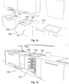
Figures 1a to 1c show a cooling appliance integrated within a worktop of a kitchen; -
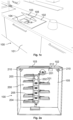
Figures 2a to 2b show different views of an item access unit within a cooling appliance; -
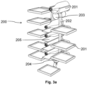
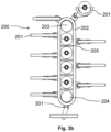
Figures 3a to 3c show different views of an item access unit; -
Figures 4a to 4b show an example item holder of an item access unit; and -
Figures 5a to 5c show an example fixing mechanism for fixing an item holder that is positioned at the access hatch of the cooling appliance. - As outlined above, the present document is directed at increasing the energy efficiency and the comfort-of-use of a cooling appliance. In this context,
Figures 1a to 1c show different views of acooling appliance 100, which is integrated within theworktop 110 of a kitchen. The coolingappliance 100 comprises a housing (e.g., a cuboid shaped housing) with an upper (i.e., top)housing wall 102. Theupper housing wall 102 may be parallel to and/or aligned with theworktop 110 of the kitchen. Theupper housing wall 102 comprises an access hatch (i.e., an opening lid) 103, which may be opened by a user to give access to theinterior 105 of the coolingappliance 100. By providing an access at the top of the housing of the coolingappliance 100, a particularly energy efficient access may be provided. - The cooling
appliance 100 may further comprise afront door 101 which may be opened by the user to provide a particular comfortable and/or relatively large access to theinterior 105 of the cooling appliance 100 (e.g., for placing a relatively large number of items within theinterior 105 of the cooling appliance 100). Thefront door 101 may be positioned at the front side of the housing of theappliance 100, which is facing the user. - The cooling
appliance 100 may further comprise auser interface 104, which allows the user to interact with the coolingappliance 100. In particular, theuser interface 104 may be used to change a setting (such as the cooling temperature) of the coolingappliance 100 and/or to select an item holder of the item access unit of the coolingappliance 100, which should be positioned at the access hatch 103 (i.e., within the top region of the cooling appliance 100). -
Figures 2a to 2b show different views of anitem access unit 200, which is located within theinterior 105 of the coolingappliance 100. Theitem access unit 200 comprises aconveyor belt 202 with adrive pulley 203 and atail pulley 204. Theconveyor belt 202 is arranged vertically within theinterior 105 of the coolingappliance 100, such that theconveyor belt 202 is moving upwards from thetail pulley 204 to the drivepulley 203, and downwards from thedrive pulley 203 to the tail pulley 204 (or vice versa). - The
item access unit 200 comprises a plurality ofitem holders 201, e.g., trays and/or bottle holders, which are attached to theconveyor belt 202.Adjacent item holders 201 may be spaced at substantially equal distances to one another. In the example shown inFig. 2a , theitem access unit 200 comprises tendifferent item holders 201, which are attached to different attachment points of theconveyer belt 202. - By moving the
conveyor belt 202different item holders 201 may be positioned directly below the access hatch 103 (i.e., in the top region of the cooling appliance 100), such that the user can access the one or more items which are placed on theitem holder 201 that is positioned below theaccess hatch 103 in a comfortable and rapid manner, thereby further increasing the energy efficiency of the coolingappliance 100. - The
item access unit 200 may comprise one or more stationary and or fixeditem holders 205, in particular bottle holders, which are located between thedrive pulley 203 and the tail pulley 204 (surrounded by the conveyor belt 202). The one or morestationary item holders 205 may be accessed via thefront door 101 of the coolingappliance 100. - The cooling
appliance 100 may comprise one ormore sensors 210, in particular cameras, which are configured to capture sensor data with regard to theinterior 105 of the coolingappliance 100. Acontrol unit 212 of the coolingappliance 100 may be configured to analyze the sensor data to identify the one or more items, which are placed within theitem access unit 200, in particular, which are placed on thedifferent item holders item access unit 200. This information may be used to enable a user to select a particular item using theuser interface 104 of the coolingappliance 100. Thecontrol unit 212 may then cause theitem access unit 200 to position theitem holder 201 with the selected item below theaccess hatch 103 of the coolingappliance 100, thereby providing a particularly comfortable and energy efficient access to the items, which are located within the coolingappliance 100. -
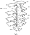
Figures 3a to 3c show different views of theitem access unit 200. In particular, it is illustrated how thedifferent item holders 201 are coupled to theconveyor belt 202 viarespective hinges 301, which are configured to maintain theindividual item holders 201 in a horizontal orientation, during a complete revolution of therespective item holder 201. As a result of this, items may be placed on theitem holders 201 in a reliable manner. -
Figures 4a and 4b shows further details regarding thehinge 301. Thehinge 301 may comprise afirst arm 401 which is attached to thebelt 202 and asecond arm 402 which is coupled to theitem holder 201 via apivot joint 403. Thefirst arm 401 and thesecond arm 402 are coupled to one another via a joint 404 that allows thefirst arm 401 and thesecond arm 402 to be held at different angles with respect to one another, as the item hold 201 revolves around thepulleys -
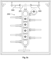
Figures 5a to 5c show afixing mechanism 500, which allows theitem holder 201 that is positioned below theaccess hatch 103 to be maintained at a fixed and stable position, thereby enabling the user to remove an item from theitem holder 201 in a comfortable and secure manner. - Hence, the cooling
appliance 100 may provide anopening lid 103 at the top, such that the cold air is preserved inside when opening thecooling appliance 100. An elevator mechanism (i.e., an item access unit) 200 is described, wherein the different shelves (i.e., item holders) 201 are connected to avertical conveyor belt 202. The user may select theshelf 201 that is to be moved to the top, where it can be accessed via theopening lid 103. - Based on the sensor data of the one or
more sensors 210, the different items, which are located within the coolingappliance 100, in particular within theitem access unit 200, may be identified, thereby providing a reliable stock management. Thecontrol unit 212 may be configured to maintain a stock list of available items. - The user may select an item from the stock list of available items via the
user interface 104. Theuser interface 104 may be configured to provide natural language processing (NLP) to allow the user to interact with the coolingappliance 100 using speech. The user may name the item, and theuser interface 104 may understand the spoken words. If the item is available, theitem holder 201 that comprises the item may be placed at the top position of theitem access unit 200. On the other hand, if the item is not available, theuser interface 104 may propose an alternative item, which is available within the cooling appliance 100 (e.g., using artificial intelligence). - The
opening lid 103 for providing access to theinterior 105 of the coolingappliance 100 may be positioned at the top portion on the front side of the coolingappliance 100, e.g. having the size of a typical kitchen drawer. - The cooling
appliance 100 described herein enables an energy efficient storage of (food) items. Furthermore, accessibility to and/or visibility of the different items is improved, thereby increasing the comfort for the user. Stock management may be improved due to an improved visibility of the different items and due to an improved computer vision. - It should be noted that the description and drawings merely illustrate the principles of the proposed methods and systems. Those skilled in the art will be able to implement various arrangements that, although not explicitly described or shown herein, embody the principles of the invention and are included within its spirit and scope as defined by the appended claims. Furthermore, all examples and embodiment outlined in the present document are principally intended expressly to be only for explanatory purposes to help the reader in understanding the principles of the proposed methods and systems. Furthermore, all statements herein providing principles, aspects, and embodiments of the invention, as well as specific examples thereof, are intended to encompass equivalents thereof.
Claims (15)
- A cooling appliance (100) for a kitchen of a household; wherein the cooling appliance (100) comprises,- an opening lid (103) which is configured to provide access to an interior (105) of the cooling appliance (100), such that the access is limited to a top region of the interior (105) of the cooling appliance (100); and- an item access unit (200) which is located within the interior (105) of the cooling appliance (100), which comprises a plurality of different item holders (201) and which is configured to move a selected one of the plurality of item holders (201) into the top region of the interior (105) of the cooling appliance (100), such that a user is enabled to access the selected item holder (201) via the opening lid (103).
- The cooling appliance (100) of claim 1, wherein- the item access unit (200) comprises a conveyor belt (202), preferably a vertical conveyor belt (202); and- the plurality of item holders (201) is attached to a corresponding plurality of attachment points of the conveyor belt (202).
- The cooling appliance (100) of claim 2, wherein an item holder (201) is attached to the conveyor belt (202) such that the item holder (201) is maintained horizontally during a complete revolution of the item holder (201).
- The cooling appliance (100) of any of claims 2 to 3, wherein the cooling appliance (100) comprises a fixing mechanism (500) which is configured to selectively hold the item holder (201) which is positioned in the top region of the interior (105) of the cooling appliance (100) in a defined and stable position.
- The cooling appliance (100) of any of claims 2 to 4, wherein- the item access unit (200) comprises a drive pulley (203) and a tail pulley (204), which are configured to move the conveyor belt (202); and- the item access unit (200) comprises one or more stationary item holders (205) which are positioned between the drive pulley (203) and the tail pulley (204) and which are surrounded by the conveyor belt (202).
- The cooling appliance (100) of any of claims 2 to 5, wherein the item holders (201) of the plurality of item holders (201) are each attached to the conveyor belt (202) using a hinge (301).
- The cooling appliance (100) of any previous claim, wherein an item holder (201) is a tray onto which an item, in particular a food item, may be placed.
- The cooling appliance (100) of any previous claim, wherein- the opening lid (103) is located at a top housing wall (102) of a housing of the cooling appliance (100); and- the top housing wall (102) and/or the opening lid (103) have a horizontal orientation.
- The cooling appliance (100) of any previous claim, wherein- the interior (105) of the cooling appliance (100) spans from a bottom wall to a top wall of a housing of the cooling appliance (100);- the cooling appliance (100) comprises a front door (101) at a front side of the housing of the cooling appliance (100); and- the front door (101) is configured to provide access to a region at the front side of the interior (105) of the cooling appliance (100) which spans from the bottom wall to the top wall of the housing of the cooling appliance (100).
- The cooling appliance (100) of any previous claim, wherein- the interior (105) of the cooling appliance (100) exhibits a certain height between a bottom wall and a top wall of a housing of the cooling appliance (100);- the top region of the interior (105) of the cooling appliance (100) starts at the top wall of the housing of the cooling appliance (100) and is limited to a distance from the top wall of the housing of the cooling appliance (100) of 20% or less of the height.
- The cooling appliance (100) of any previous claim, wherein the cooling appliance (100) comprises- a sensor (210), in particular a camera, which is configured to capture sensor data regarding items placed within the item access unit (200); and- a control unit (212) which is configured to identify the items placed within the item access unit (200) based on the sensor data.
- The cooling appliance (100) of claim 11, wherein the control unit (212) is configured to- determine for an, in particular for each, identified item the item holder (201) of the plurality of item holders (201) that the identified item is placed on; and- manage a list of the items which are placed within the item access unit (200) and of the item holders (201) that the respective items are placed on.
- The cooling appliance (100) of claim 12, wherein the control unit (212) is configured to- determine, in particular via a user interface (104) of the cooling appliance (100), a particular item that the user of the cooling appliance (100) wants to access;- based on the managed list, cause the item access unit (200) to move the item holder (201) that the particular item is placed on into the top region of the interior (105) of the cooling appliance (100); and- in particular, indicate to the user via the user interface (104) that the particular item is ready for access at the top region of the interior (105) of the cooling appliance (100).
- The cooling appliance (100) of any previous claim, wherein the cooling appliance (100) comprises a user interface (104) which is configured to allow the user to select an item, which is to accessed through the opening lid (103), using natural language processing.
- The cooling appliance (100) of any previous claim, wherein the cooling appliance (100) is configured to be integrated within a worktop (110) of a kitchen, in particular such that the closed opening lid (103) is aligned with the worktop (110).
Priority Applications (1)
| Application Number | Priority Date | Filing Date | Title |
|---|---|---|---|
| EP23193621.2A EP4517235A1 (en) | 2023-08-28 | 2023-08-28 | Cooling appliance with an item access unit |
Applications Claiming Priority (1)
| Application Number | Priority Date | Filing Date | Title |
|---|---|---|---|
| EP23193621.2A EP4517235A1 (en) | 2023-08-28 | 2023-08-28 | Cooling appliance with an item access unit |
Publications (1)
| Publication Number | Publication Date |
|---|---|
| EP4517235A1 true EP4517235A1 (en) | 2025-03-05 |
Family
ID=87847923
Family Applications (1)
| Application Number | Title | Priority Date | Filing Date |
|---|---|---|---|
| EP23193621.2A Pending EP4517235A1 (en) | 2023-08-28 | 2023-08-28 | Cooling appliance with an item access unit |
Country Status (1)
| Country | Link |
|---|---|
| EP (1) | EP4517235A1 (en) |
Citations (6)
| Publication number | Priority date | Publication date | Assignee | Title |
|---|---|---|---|---|
| US1785954A (en) * | 1929-06-26 | 1930-12-23 | Frederick S Hayes | Dispensing refrigerator |
| JP2003090661A (en) * | 2001-09-20 | 2003-03-28 | Hitachi Ltd | Storage with private room and its control method |
| US20060137375A1 (en) * | 2004-06-01 | 2006-06-29 | William Lishman | Appliance with movable carriage for storing goods |
| US20080092582A1 (en) * | 2006-09-20 | 2008-04-24 | John Doran | Rotating freezer unit |
| US20090229293A1 (en) * | 2004-10-29 | 2009-09-17 | Byung-Chul Kim | Cooler of Table-Type |
| US20190316836A1 (en) * | 2016-05-25 | 2019-10-17 | Sungkang Egs Co., Ltd | Smart repository |
-
2023
- 2023-08-28 EP EP23193621.2A patent/EP4517235A1/en active Pending
Patent Citations (6)
| Publication number | Priority date | Publication date | Assignee | Title |
|---|---|---|---|---|
| US1785954A (en) * | 1929-06-26 | 1930-12-23 | Frederick S Hayes | Dispensing refrigerator |
| JP2003090661A (en) * | 2001-09-20 | 2003-03-28 | Hitachi Ltd | Storage with private room and its control method |
| US20060137375A1 (en) * | 2004-06-01 | 2006-06-29 | William Lishman | Appliance with movable carriage for storing goods |
| US20090229293A1 (en) * | 2004-10-29 | 2009-09-17 | Byung-Chul Kim | Cooler of Table-Type |
| US20080092582A1 (en) * | 2006-09-20 | 2008-04-24 | John Doran | Rotating freezer unit |
| US20190316836A1 (en) * | 2016-05-25 | 2019-10-17 | Sungkang Egs Co., Ltd | Smart repository |
Similar Documents
| Publication | Publication Date | Title |
|---|---|---|
| EP3739536A1 (en) | An automated outdoor terminal for storage and handover of online grocery orders and a method to operate the terminal | |
| CN109804416B (en) | Modular vending machine | |
| CN105184975B (en) | Automatic vending machine management system and management method | |
| US7937289B2 (en) | Method and apparatus for monitoring unit depletion in an independent real-time mass storage unit system by using an estimated tare mass of the item | |
| US10154756B2 (en) | Automated kitchen workspace with robot | |
| EP3695178B1 (en) | Refrigerator icemaking system with tandem storage bins and removable dispenser recess | |
| CN104110936A (en) | Refrigerator And Operating Method Thereof | |
| KR102065970B1 (en) | Vending machine | |
| CN112136014A (en) | Refrigerator system | |
| KR102017980B1 (en) | Refrigerator with displaying image by identifying goods using artificial intelligence and method of displaying thereof | |
| US10945524B2 (en) | Refrigerator | |
| JP2002318060A (en) | Refrigerator with food management function | |
| US11633065B2 (en) | Automated food preparation system | |
| US20230058922A1 (en) | Appliance with collocated cameras | |
| KR102154041B1 (en) | A sliding refrigerator monitoring food and control method thereof | |
| US20060162369A1 (en) | Refrigerator | |
| CA3172848A1 (en) | Gesture operated refrigerated display case | |
| US7530473B2 (en) | Thermal separating door in a vending machine | |
| KR101902950B1 (en) | Storage device for a vehicle with an image-capturing device | |
| CN104246399B (en) | There is the refrigerating appliance of cold lattice | |
| EP3281185B1 (en) | Intake mechanism for a merchandiser | |
| WO2019109491A1 (en) | Refrigerator icemaking console | |
| US20200058185A1 (en) | Food Frying and Distribution Device | |
| KR102360350B1 (en) | Apparatus for supplying raw material | |
| KR20190056950A (en) | Receipt device for kitchen |
Legal Events
| Date | Code | Title | Description |
|---|---|---|---|
| PUAI | Public reference made under article 153(3) epc to a published international application that has entered the european phase |
Free format text: ORIGINAL CODE: 0009012 |
|
| STAA | Information on the status of an ep patent application or granted ep patent |
Free format text: STATUS: THE APPLICATION HAS BEEN PUBLISHED |
|
| AK | Designated contracting states |
Kind code of ref document: A1 Designated state(s): AL AT BE BG CH CY CZ DE DK EE ES FI FR GB GR HR HU IE IS IT LI LT LU LV MC ME MK MT NL NO PL PT RO RS SE SI SK SM TR |
|
| STAA | Information on the status of an ep patent application or granted ep patent |
Free format text: STATUS: REQUEST FOR EXAMINATION WAS MADE |
|
| 17P | Request for examination filed |
Effective date: 20250905 |