EP4517221A1 - Microchannel heat exchanger group and air conditioning system having same - Google Patents
Microchannel heat exchanger group and air conditioning system having same Download PDFInfo
- Publication number
- EP4517221A1 EP4517221A1 EP23795561.2A EP23795561A EP4517221A1 EP 4517221 A1 EP4517221 A1 EP 4517221A1 EP 23795561 A EP23795561 A EP 23795561A EP 4517221 A1 EP4517221 A1 EP 4517221A1
- Authority
- EP
- European Patent Office
- Prior art keywords
- heat exchanger
- tubes
- flat tubes
- group
- circulation path
- Prior art date
- Legal status (The legal status is an assumption and is not a legal conclusion. Google has not performed a legal analysis and makes no representation as to the accuracy of the status listed.)
- Pending
Links
Images


Classifications
-
- F—MECHANICAL ENGINEERING; LIGHTING; HEATING; WEAPONS; BLASTING
- F28—HEAT EXCHANGE IN GENERAL
- F28D—HEAT-EXCHANGE APPARATUS, NOT PROVIDED FOR IN ANOTHER SUBCLASS, IN WHICH THE HEAT-EXCHANGE MEDIA DO NOT COME INTO DIRECT CONTACT
- F28D1/00—Heat-exchange apparatus having stationary conduit assemblies for one heat-exchange medium only, the media being in contact with different sides of the conduit wall, in which the other heat-exchange medium is a large body of fluid, e.g. domestic or motor car radiators
- F28D1/02—Heat-exchange apparatus having stationary conduit assemblies for one heat-exchange medium only, the media being in contact with different sides of the conduit wall, in which the other heat-exchange medium is a large body of fluid, e.g. domestic or motor car radiators with heat-exchange conduits immersed in the body of fluid
- F28D1/04—Heat-exchange apparatus having stationary conduit assemblies for one heat-exchange medium only, the media being in contact with different sides of the conduit wall, in which the other heat-exchange medium is a large body of fluid, e.g. domestic or motor car radiators with heat-exchange conduits immersed in the body of fluid with tubular conduits
- F28D1/047—Heat-exchange apparatus having stationary conduit assemblies for one heat-exchange medium only, the media being in contact with different sides of the conduit wall, in which the other heat-exchange medium is a large body of fluid, e.g. domestic or motor car radiators with heat-exchange conduits immersed in the body of fluid with tubular conduits the conduits being bent, e.g. in a serpentine or zig-zag
- F28D1/0477—Heat-exchange apparatus having stationary conduit assemblies for one heat-exchange medium only, the media being in contact with different sides of the conduit wall, in which the other heat-exchange medium is a large body of fluid, e.g. domestic or motor car radiators with heat-exchange conduits immersed in the body of fluid with tubular conduits the conduits being bent, e.g. in a serpentine or zig-zag the conduits being bent in a serpentine or zig-zag
-
- F—MECHANICAL ENGINEERING; LIGHTING; HEATING; WEAPONS; BLASTING
- F24—HEATING; RANGES; VENTILATING
- F24F—AIR-CONDITIONING; AIR-HUMIDIFICATION; VENTILATION; USE OF AIR CURRENTS FOR SCREENING
- F24F13/00—Details common to, or for air-conditioning, air-humidification, ventilation or use of air currents for screening
- F24F13/30—Arrangement or mounting of heat-exchangers
-
- F—MECHANICAL ENGINEERING; LIGHTING; HEATING; WEAPONS; BLASTING
- F25—REFRIGERATION OR COOLING; COMBINED HEATING AND REFRIGERATION SYSTEMS; HEAT PUMP SYSTEMS; MANUFACTURE OR STORAGE OF ICE; LIQUEFACTION SOLIDIFICATION OF GASES
- F25B—REFRIGERATION MACHINES, PLANTS OR SYSTEMS; COMBINED HEATING AND REFRIGERATION SYSTEMS; HEAT PUMP SYSTEMS
- F25B39/00—Evaporators; Condensers
-
- F—MECHANICAL ENGINEERING; LIGHTING; HEATING; WEAPONS; BLASTING
- F28—HEAT EXCHANGE IN GENERAL
- F28D—HEAT-EXCHANGE APPARATUS, NOT PROVIDED FOR IN ANOTHER SUBCLASS, IN WHICH THE HEAT-EXCHANGE MEDIA DO NOT COME INTO DIRECT CONTACT
- F28D1/00—Heat-exchange apparatus having stationary conduit assemblies for one heat-exchange medium only, the media being in contact with different sides of the conduit wall, in which the other heat-exchange medium is a large body of fluid, e.g. domestic or motor car radiators
- F28D1/02—Heat-exchange apparatus having stationary conduit assemblies for one heat-exchange medium only, the media being in contact with different sides of the conduit wall, in which the other heat-exchange medium is a large body of fluid, e.g. domestic or motor car radiators with heat-exchange conduits immersed in the body of fluid
- F28D1/04—Heat-exchange apparatus having stationary conduit assemblies for one heat-exchange medium only, the media being in contact with different sides of the conduit wall, in which the other heat-exchange medium is a large body of fluid, e.g. domestic or motor car radiators with heat-exchange conduits immersed in the body of fluid with tubular conduits
- F28D1/047—Heat-exchange apparatus having stationary conduit assemblies for one heat-exchange medium only, the media being in contact with different sides of the conduit wall, in which the other heat-exchange medium is a large body of fluid, e.g. domestic or motor car radiators with heat-exchange conduits immersed in the body of fluid with tubular conduits the conduits being bent, e.g. in a serpentine or zig-zag
-
- F—MECHANICAL ENGINEERING; LIGHTING; HEATING; WEAPONS; BLASTING
- F28—HEAT EXCHANGE IN GENERAL
- F28D—HEAT-EXCHANGE APPARATUS, NOT PROVIDED FOR IN ANOTHER SUBCLASS, IN WHICH THE HEAT-EXCHANGE MEDIA DO NOT COME INTO DIRECT CONTACT
- F28D1/00—Heat-exchange apparatus having stationary conduit assemblies for one heat-exchange medium only, the media being in contact with different sides of the conduit wall, in which the other heat-exchange medium is a large body of fluid, e.g. domestic or motor car radiators
- F28D1/02—Heat-exchange apparatus having stationary conduit assemblies for one heat-exchange medium only, the media being in contact with different sides of the conduit wall, in which the other heat-exchange medium is a large body of fluid, e.g. domestic or motor car radiators with heat-exchange conduits immersed in the body of fluid
- F28D1/04—Heat-exchange apparatus having stationary conduit assemblies for one heat-exchange medium only, the media being in contact with different sides of the conduit wall, in which the other heat-exchange medium is a large body of fluid, e.g. domestic or motor car radiators with heat-exchange conduits immersed in the body of fluid with tubular conduits
- F28D1/047—Heat-exchange apparatus having stationary conduit assemblies for one heat-exchange medium only, the media being in contact with different sides of the conduit wall, in which the other heat-exchange medium is a large body of fluid, e.g. domestic or motor car radiators with heat-exchange conduits immersed in the body of fluid with tubular conduits the conduits being bent, e.g. in a serpentine or zig-zag
- F28D1/0475—Heat-exchange apparatus having stationary conduit assemblies for one heat-exchange medium only, the media being in contact with different sides of the conduit wall, in which the other heat-exchange medium is a large body of fluid, e.g. domestic or motor car radiators with heat-exchange conduits immersed in the body of fluid with tubular conduits the conduits being bent, e.g. in a serpentine or zig-zag the conduits having a single U-bend
- F28D1/0476—Heat-exchange apparatus having stationary conduit assemblies for one heat-exchange medium only, the media being in contact with different sides of the conduit wall, in which the other heat-exchange medium is a large body of fluid, e.g. domestic or motor car radiators with heat-exchange conduits immersed in the body of fluid with tubular conduits the conduits being bent, e.g. in a serpentine or zig-zag the conduits having a single U-bend the conduits having a non-circular cross-section
-
- F—MECHANICAL ENGINEERING; LIGHTING; HEATING; WEAPONS; BLASTING
- F28—HEAT EXCHANGE IN GENERAL
- F28D—HEAT-EXCHANGE APPARATUS, NOT PROVIDED FOR IN ANOTHER SUBCLASS, IN WHICH THE HEAT-EXCHANGE MEDIA DO NOT COME INTO DIRECT CONTACT
- F28D1/00—Heat-exchange apparatus having stationary conduit assemblies for one heat-exchange medium only, the media being in contact with different sides of the conduit wall, in which the other heat-exchange medium is a large body of fluid, e.g. domestic or motor car radiators
- F28D1/02—Heat-exchange apparatus having stationary conduit assemblies for one heat-exchange medium only, the media being in contact with different sides of the conduit wall, in which the other heat-exchange medium is a large body of fluid, e.g. domestic or motor car radiators with heat-exchange conduits immersed in the body of fluid
- F28D1/04—Heat-exchange apparatus having stationary conduit assemblies for one heat-exchange medium only, the media being in contact with different sides of the conduit wall, in which the other heat-exchange medium is a large body of fluid, e.g. domestic or motor car radiators with heat-exchange conduits immersed in the body of fluid with tubular conduits
- F28D1/053—Heat-exchange apparatus having stationary conduit assemblies for one heat-exchange medium only, the media being in contact with different sides of the conduit wall, in which the other heat-exchange medium is a large body of fluid, e.g. domestic or motor car radiators with heat-exchange conduits immersed in the body of fluid with tubular conduits the conduits being straight
- F28D1/0535—Heat-exchange apparatus having stationary conduit assemblies for one heat-exchange medium only, the media being in contact with different sides of the conduit wall, in which the other heat-exchange medium is a large body of fluid, e.g. domestic or motor car radiators with heat-exchange conduits immersed in the body of fluid with tubular conduits the conduits being straight the conduits having a non-circular cross-section
- F28D1/05366—Assemblies of conduits connected to common headers, e.g. core type radiators
- F28D1/05391—Assemblies of conduits connected to common headers, e.g. core type radiators with multiple rows of conduits or with multi-channel conduits combined with a particular flow pattern, e.g. multi-row multi-stage radiators
-
- F—MECHANICAL ENGINEERING; LIGHTING; HEATING; WEAPONS; BLASTING
- F28—HEAT EXCHANGE IN GENERAL
- F28F—DETAILS OF HEAT-EXCHANGE AND HEAT-TRANSFER APPARATUS, OF GENERAL APPLICATION
- F28F1/00—Tubular elements; Assemblies of tubular elements
- F28F1/02—Tubular elements of cross-section which is non-circular
- F28F1/022—Tubular elements of cross-section which is non-circular with multiple channels
-
- F—MECHANICAL ENGINEERING; LIGHTING; HEATING; WEAPONS; BLASTING
- F28—HEAT EXCHANGE IN GENERAL
- F28F—DETAILS OF HEAT-EXCHANGE AND HEAT-TRANSFER APPARATUS, OF GENERAL APPLICATION
- F28F9/00—Casings; Header boxes; Auxiliary supports for elements; Auxiliary members within casings
- F28F9/02—Header boxes; End plates
- F28F9/026—Header boxes; End plates with static flow control means, e.g. with means for uniformly distributing heat exchange media into conduits
- F28F9/027—Header boxes; End plates with static flow control means, e.g. with means for uniformly distributing heat exchange media into conduits in the form of distribution pipes
- F28F9/0275—Header boxes; End plates with static flow control means, e.g. with means for uniformly distributing heat exchange media into conduits in the form of distribution pipes with multiple branch pipes
-
- F—MECHANICAL ENGINEERING; LIGHTING; HEATING; WEAPONS; BLASTING
- F28—HEAT EXCHANGE IN GENERAL
- F28F—DETAILS OF HEAT-EXCHANGE AND HEAT-TRANSFER APPARATUS, OF GENERAL APPLICATION
- F28F9/00—Casings; Header boxes; Auxiliary supports for elements; Auxiliary members within casings
- F28F9/26—Arrangements for connecting different sections of heat-exchange elements, e.g. of radiators
-
- F—MECHANICAL ENGINEERING; LIGHTING; HEATING; WEAPONS; BLASTING
- F28—HEAT EXCHANGE IN GENERAL
- F28D—HEAT-EXCHANGE APPARATUS, NOT PROVIDED FOR IN ANOTHER SUBCLASS, IN WHICH THE HEAT-EXCHANGE MEDIA DO NOT COME INTO DIRECT CONTACT
- F28D21/00—Heat-exchange apparatus not covered by any of the groups F28D1/00 - F28D20/00
- F28D2021/0019—Other heat exchangers for particular applications; Heat exchange systems not otherwise provided for
- F28D2021/0068—Other heat exchangers for particular applications; Heat exchange systems not otherwise provided for for refrigerant cycles
-
- F—MECHANICAL ENGINEERING; LIGHTING; HEATING; WEAPONS; BLASTING
- F28—HEAT EXCHANGE IN GENERAL
- F28F—DETAILS OF HEAT-EXCHANGE AND HEAT-TRANSFER APPARATUS, OF GENERAL APPLICATION
- F28F1/00—Tubular elements; Assemblies of tubular elements
- F28F1/10—Tubular elements and assemblies thereof with means for increasing heat-transfer area, e.g. with fins, with projections, with recesses
- F28F1/12—Tubular elements and assemblies thereof with means for increasing heat-transfer area, e.g. with fins, with projections, with recesses the means being only outside the tubular element
- F28F1/24—Tubular elements and assemblies thereof with means for increasing heat-transfer area, e.g. with fins, with projections, with recesses the means being only outside the tubular element and extending transversely
- F28F1/32—Tubular elements and assemblies thereof with means for increasing heat-transfer area, e.g. with fins, with projections, with recesses the means being only outside the tubular element and extending transversely the means having portions engaging further tubular elements
-
- F—MECHANICAL ENGINEERING; LIGHTING; HEATING; WEAPONS; BLASTING
- F28—HEAT EXCHANGE IN GENERAL
- F28F—DETAILS OF HEAT-EXCHANGE AND HEAT-TRANSFER APPARATUS, OF GENERAL APPLICATION
- F28F2260/00—Heat exchangers or heat exchange elements having special size, e.g. microstructures
- F28F2260/02—Heat exchangers or heat exchange elements having special size, e.g. microstructures having microchannels
Definitions
- the present application relates to the field of refrigeration, in particular, to a microchannel heat exchanger group and an air conditioning system having the same.
- Microchannel heat exchanger groups belong to a class of compact, lightweight and highly efficient heat exchangers designed to meet the needs of industrial development.
- a refrigeration system usually needs a set of microchannel heat exchanger corresponding to the refrigeration system, which makes the heat exchange of the fins in the microchannel heat exchanger cannot be fully utilized, and thus reduces the heat exchange efficiency of the microchannel heat exchanger.
- a microchannel heat exchanger group capable of improving the thermal efficiency of the microchannel heat exchanger group and an air conditioning system including the same are provided on the basis of embodiments of the present application.
- the present application provides a following technical solution.
- a microchannel heat exchanger group including a plurality of fins, wherein the plurality of fins are arranged in a plurality of rows, and each of the plurality of fins are provided with insertion slots; wherein the microchannel heat exchanger group further at least includes a first heat exchanger and a second heat exchanger, the first heat exchanger includes a plurality of first flat tubes, the second heat exchanger includes a plurality of second flat tubes, the plurality of first flat tubes and the plurality of second flat tubes are arranged in a plurality of layers along a length direction of each of the plurality of fins, the plurality of first flat tubes and the plurality of second flat tubes are arranged in a plurality of rows along a width direction of each of the plurality of fins; the insertion slots include a first insertion slot and a second insertion slot, the plurality of first flat tubes are inserted into the first insertion slot, the plurality of second flat tubes are inserted into the second insertion slot, and the plurality of first flat tubes are separated from the pluralit
- the microchannel heat exchanger group further includes a first heat exchanger and a second heat exchanger independent of each other, when one of the first heat exchanger and the second heat exchanger is out of work, the other one of the first heat exchanger and the second heat exchanger can make full use of the heat exchange area of the plurality of fins to exchange heat, thereby improving an energy efficiency of the microchannel heat exchanger group.
- the plurality of first flat tubes and the plurality of second flat tubes alternate with each other along the length direction of the plurality of fins.
- the other one of the first heat exchanger and the second heat exchanger can further make full use of the heat exchange area of the plurality of fins to exchange heat, thereby improving an energy efficiency of the microchannel heat exchanger group.
- the first heat exchanger includes a first connector assembly and a second connector assembly, each of the plurality of first flat tubes, the first connector assembly and the second connector assembly are connected to and in communication with each other, a first circulation path is defined by a refrigerant flowing into one of the plurality of first flat tubes from the first connector assembly, and flowing out from the second connector assembly; and the second heat exchanger includes a third connector assembly and a fourth connector assembly, each of the plurality of second flat tubes, the third connector assembly and the fourth connector assembly are connected to and in communication with each other, a second circulation path is defined by the refrigerant flowing into one of the plurality of first flat tubes from the third connector assembly, and flowing out from the fourth connector assembly; wherein a group of the first circulation path and a group of the second circulation path and are isolated from one another, the number of the first circulation path in the group of the first circulation path is defined as M , the number of the second circulation path in the group of the second circulation path is defined as N, and both the number M of the first circulation
- the insertion slots are disposed at a same side of the plurality of fins, the insertion slots at adjacent rows of the plurality of fins alternate with each other; optionally wherein both sides of each of the plurality of fins are provided with the insertion slots, and the insertion slots disposed at both sides of each of the plurality of fins alternate with each other.
- the first connector assembly includes a first distributor and a plurality of first capillary tubes being connected to and in communication with the first distributor, both ends of each of the plurality of first capillary tubes are connected to and in communication with the first distributor and corresponding one of the plurality of first flat tubes, respectively; and the third connector assembly includes a second distributor and a plurality of second capillary tubes being connected to and in communication with the second distributor, both ends of each of the plurality of second capillary tubes are connected to and in communication with the second distributor and corresponding one of the plurality of second flat tubes, respectively.
- the refrigerant flows into the plurality of first flat tubes and the plurality of second flat tubes after the refrigerant is evenly distributed by the first distributor and the second distributor, and the processing is simplified.
- the second connector assembly includes a first collecting tube and a plurality of first connecting tubes being connected to and in communication with the first collecting tube, both ends of each of the plurality of the first connecting tubes are connected to and in communication with the first collecting tube and corresponding one of the plurality of first flat tubes; and the fourth connector assembly includes a second collecting tube and a plurality of second connecting tubes being connected to and in communication with the second collecting tube, both ends of each of the plurality of the second connecting tubes are connected to and in communication with the second collecting tube and corresponding one of the plurality of second flat tubes.
- first collecting tube and the second collecting tube it could be understood that by disposing the first collecting tube and the second collecting tube, it is convenient to collect the refrigerant in the first flat tube and the second flat tube.
- both the plurality of first flat tubes and the plurality of second flat tubes are arranged in a plurality of rows
- the first heat exchanger includes a plurality of first bending tubes
- the second heat exchanger comprises a plurality of second bending tubes
- the first flat tubes arranged in adjacent rows of the plurality of first flat tubes are connected to and in communication with each other via corresponding one of the plurality of first bending tubes, and the plurality of first bending tubes and the plurality of first flat tubes are separately arranged
- the second flat tubes arranged in adjacent rows of the plurality of second flat tubes are connected to and in communication with each other via corresponding one of the plurality of second bending tubes, and the plurality of second bending tubes and the plurality of second flat tubes are separately arranged.
- the microchannel heat exchanger group includes a plurality of first bending tubes and a plurality of second bending tubes, the refrigerant can make a turn, and deformation of the plurality of fins caused by bending of the plurality of fins can be avoided.
- the microchannel heat exchanger group further includes an adapter, the adapter is disposed between the plurality of first capillary tubes and the plurality of first flat tubes and between the plurality of second capillary tubes and the plurality of second flat tubes, and a tube orifice of the adapter opposite to the plurality of first flat tubes matches with a tube orifice of corresponding one of the plurality of first flat tube and another tube orifice of the adapter opposite the plurality of second flat tubes matches with a tube orifice of corresponding one of the plurality of second flat tube.
- An air conditioning system which includes a microchannel heat exchanger group.
- the microchannel heat exchanger group further includes a first heat exchanger and a second heat exchanger independent of each other, when one of the first heat exchanger and the second heat exchanger is out of work, the other one of the first heat exchanger and the second heat exchanger can make full use of the heat exchange area of the plurality of fins to exchange heat, thereby improving an energy efficiency of the microchannel heat exchanger group.
- first, second are used for descriptive purposes only and are not to be understood as indicating or implying relative importance or implicitly specifying the number of technical features indicated.
- a feature defined with the terms “first”, “second” may include at least one such feature, either explicitly or implicitly.
- plural means at least two, e.g., two, three, etc., unless otherwise expressly and specifically limited.
- the first feature "on” or “under” the second feature may be that the first feature is in direct contact with the second feature, or that the first feature is in indirect contact with the second feature through an intermediate medium.
- the first feature being “above”, “on” or “upon” the second feature may mean that the first feature is directly above or diagonally above the second feature, or it may simply mean that the first feature is horizontally higher than the second feature.
- the first feature being “below”, “under” or “beneath” the second feature may be that the first feature is directly below or diagonally below the second feature, or it may simply mean that the first feature is horizontally smaller than the second feature.
- a microchannel heat exchanger group 100 is provided in the present application, which is disposed in the air conditioning system.
- a medium flows in the microchannel heat exchanger group 100, and the microchannel heat exchanger group 100 can facilitate heat exchange between the medium and the outside world.
- a refrigeration system usually needs a set of microchannel heat exchanger corresponding to the refrigeration system, which makes the heat exchange of the fins in the microchannel heat exchanger cannot be fully utilized, and thus reduces the heat exchange efficiency of the microchannel heat exchanger.
- a microchannel heat exchanger group 100 is provided in the present application.
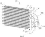
- the microchannel heat exchanger group 100 includes a plurality of fins 10, wherein the plurality of fins 10 are arranged in a plurality of rows, each of the plurality of fins 10 are provided with insertion slots 11, and a first flat tube 21 and a second flat tube 31 extends in the insertion slots 11.
- the microchannel heat exchanger group 100 further includes at least a first heat exchanger 20 and a second heat exchanger 30 independent of the first heat exchanger 20.
- the first heat exchanger 20 includes a plurality of first flat tubes 21, and the second heat exchanger 30 includes a plurality of second flat tubes 31.
- the plurality of first flat tubes 21 and the plurality of second flat tubes 31 are arranged in a plurality of layers along a length direction of each of the plurality of fins 10, and the plurality of first flat tubes 21 and the plurality of second flat tubes 31 are arranged in a plurality of rows along a width direction of each of the plurality of fins 10.
- the insertion slots 11 include a first insertion slot 111 and a second insertion slot 112, the plurality of first flat tubes 21 are inserted into the first insertion slot 111, and the plurality of second flat tubes 31 are inserted into the second insertion slot 112.
- the plurality of first flat tubes 21 are separated from the plurality of second flat tubes 31, and plurality of first flat tubes 21 are not in communication with the plurality of second flat tubes 31.
- the microchannel heat exchanger group 100 includes at least two heat exchangers. Arrangement of at least two heat exchangers independent of each other in the same set of fins 10 of the heat exchanger have following advantages.
- operation of each of the heat exchangers can be controlled according to actual conditions, so that compatibility performances of the microchannel heat exchanger group 100 can be improved; in another aspect, when one of the first heat exchanger 20 and the second heat exchanger 30 is out of work, the other one of the first heat exchanger 20 and the second heat exchanger 30 can make full use of the heat exchange area of the plurality of fins 10 to exchange heat, thereby improving an energy efficiency of the microchannel heat exchanger group.
- the plurality of fins 10 extend along a vertical direction, and the plurality of fins 10 are parallelly arranged in a plurality of rows.
- the plurality of first flat tubes 21 and the plurality of second flat tubes 31 extend along a horizontal direction.
- the plurality of first flat tubes 21 and the plurality of second flat tubes 31 are successively arranged and arranged in a plurality of layers.
- the plurality of layers of first flat tubes 21 and the plurality of layers of second flat tubes 31 are arranged along the horizontal direction in a plurality of rows.
- the plurality of first flat tubes 21 and the plurality of second flat tubes 31 are arranged in a plurality of layers and a plurality of rows.
- the microchannel heat exchanger group 100 at least includes a first heat exchanger 20 and a second heat exchanger 30 indicates that the microchannel heat exchanger group 100 at least includes two independent heat exchangers.
- the microchannel heat exchanger group 100 can further include a third heat exchanger, a fourth heat exchanger, a fifth heat exchanger and even more heat exchangers, which are not limited herein.
- a microchannel heat exchanger 100 is taken as an example.
- each of the plurality of fins 10 extends along the vertical direction, the plurality of fins 10 are parallelly arranged along the horizontal direction in a plurality of rows.
- the insertion slots 11 are disposed at the same side of the fins 10 in each row of the plurality of rows of the fins 10, and the insertion slots 10 in adjacent rows of the plurality of rows of ins 10 are staggered, so that the contact area between the flat tube and the fin 10 is great, improving the heat exchange efficiency of the heat exchanger group 100.
- both sides of each of the plurality of rows of fins are provided with the insertion slots 11, and the insertion slots 11 at both sides of each of the plurality of fins 10 are staggered.
- the flat tubes extend through each of the staggered insertion slots 11.
- the flat tubes extend along the horizontal direction. Since the flat tubes are staggered, the contact area between the flat tubes and the air is greater, so that the heat exchange efficiency of the microchannel heat exchanger group 100 is improved.
- the first heat exchanger 20 includes a first connector assembly 22 and a second connector assembly 23.
- the first connector assembly 22 includes a first distributor 221 and a plurality of first capillary tubes 222 being connected to and in communication with the first distributor 221. Both ends of each of the plurality of first capillary tubes 222 are connected to and in communication with the first distributor 221 and corresponding one of the plurality of first flat tubes 21, respectively.
- the refrigerant in the first distributor 221 are distributed into each of the plurality of first flat tubes 21 via the plurality of first capillary tubes 222. That is, the refrigerant flows into the first distributor 221 from an end of the first distributor 221 away from the first capillary tube 222.
- an outlet of the first distributor 221 is provided with a plurality of small holes being connected to and in communication with the plurality of first capillary tubes 222
- an end of each of the plurality of first capillary tubes 222 are correspondingly connected to and in communication with each of the small holes of the outlet of the first distributor 211
- the other end of each of the plurality of first capillary tubes 222 are correspondingly connected to and in communication with each of the plurality of first flat tubes 21 of the microchannel heat exchanger group 100.
- the refrigerant flows into each of the plurality of first flat tubes 21 via each of the plurality of first capillary tubes 222, so that the refrigerant is distributed into each of the plurality of first capillary tubes 222 more evenly.
- the second connector assembly 23 includes a first collecting tube 231 and a plurality of first connecting tubes 232 being connected to and in communication with the first collecting tube 231. Both ends of each of the plurality of the first connecting tubes 232 are connected to and in communication with the first collecting tube 231 and corresponding one of the plurality of first flat tubes 21. The refrigerant in the plurality of first flat tubes 21 are gathered in the first collecting tube 231 via the plurality of first connecting tubes 232. That is, the first collecting tube 231 is provided with a plurality of flowing holes configured for communicating the first connecting tubes 232.
- each of the plurality of first connecting tubes 232 are connected to and in communication with each of the plurality of flowing holes on the first collecting tubes 231, respectively; and the other end of each of the plurality of first connecting tubes 232 are connected to and in communication with each of the plurality of first flat tubes 21 of the microchannel heat exchanger 100, respectively.
- the refrigerant flows into each of the plurality of first flat tubes 21 via each of the plurality of first capillary tubes 222, and then flows into each of the plurality of first connecting tubes 232, and the flows into and gathers in the first collecting tube 231 from the plurality of first connecting tubes 232, and then entirely flows out from the first collecting tube 231. Therefore, a heat exchange circulation process in the first heat exchanger 20 is accomplished.
- the second heat exchanger 30 includes a third connector assembly 32 and a fourth connector assembly 33.
- the third connector assembly 32 includes a second distributor 321 and a plurality of second capillary tubes 322 being connected to and in communication with the second distributor 321. Both ends of each of the plurality of second capillary tubes 322 are connected to and in communication with the second distributor 321 and corresponding one of the plurality of second flat tubes 31, respectively.
- the refrigerant in the second distributor 321 are distributed into each of the plurality of second flat tubes 31 via the plurality of second capillary tubes 322. That is, the refrigerant flows into the second distributor 321 from an end of the second distributor 321 away from the second capillary tube 322.
- an outlet of the second distributor 321 is provided with a plurality of small holes being connected to and in communication with the plurality of second capillary tubes 322, an end of each of the plurality of second capillary tubes 322 are correspondingly connected to and in communication with each of the small holes of the outlet of the second distributor 321, and the other end of each of the plurality of second capillary tubes 322 are correspondingly connected to and in communication with each of the plurality of second flat tubes 31 of the microchannel heat exchanger group 100.
- the refrigerant flows into each of the plurality of second flat tubes 31 via each of the plurality of second capillary tubes 322, so that the refrigerant is distributed into each of the plurality of second capillary tubes 322 more evenly.
- the fourth connector assembly 33 includes a second collecting tube 331 and a plurality of second connecting tubes 332 being connected to and in communication with the second collecting tube 331. Both ends of each of the plurality of the second connecting tubes 332 are connected to and in communication with the second collecting tube 331 and corresponding one of the plurality of second flat tubes 31.
- the refrigerant in the plurality of second flat tubes 31 are gathered in the second collecting tube 331 via the plurality of second connecting tubes 332. That is, the second collecting tube 331 is provided with a plurality of flowing holes configured for communicating the second connecting tubes 332.
- each of the plurality of second connecting tubes 332 are connected to and in communication with each of the plurality of flowing holes on the second collecting tubes 331, respectively; and the other end of each of the plurality of second connecting tubes 332 are connected to and in communication with each of the plurality of second flat tubes 31 of the microchannel heat exchanger 100, respectively.
- the refrigerant flows into each of the plurality of second flat tubes 31 via each of the plurality of second capillary tubes 322, and then flows into each of the plurality of second connecting tubes 332, and the flows into and gathers in the second collecting tube 331 from the plurality of second connecting tubes 332, and then entirely flows out from the second collecting tube 331. Therefore, a heat exchange circulation process in the second heat exchanger 30 is accomplished.
- the plurality of first flat tubes 21 and the plurality of second flat tubes 31 alternate with each other and separated from each other. In this way, when one of the first heat exchanger 20 and the second heat exchanger 30 is out of work, the other one of the first heat exchanger 20 and the second heat exchanger 30 can make full use of the heat exchange area of the plurality of fins 10 to exchange heat, thereby improving an energy efficiency of the microchannel heat exchanger group 100.
- first flat tubes 21 are parallelly arranged in an upper section of the microchannel heat exchanger group 100
- all of the second flat tubes 31 are correspondingly arranged in a lower section of the microchannel heat exchanger group 100; optionally, when all of the first flat tubes 21 are parallelly arranged in the lower section of the microchannel heat exchanger group 100, all of the second flat tubes 31 are correspondingly arranged in the upper section of the microchannel heat exchanger group 100. Therefore, when one of the first heat exchanger 20 and the second heat exchanger 30 is out of work, the first flat tube 21 or the second flat tube 31 can only make use of a half of the area of the fins 10 in the microchannel heat exchanger group 100 to exchange heat.
- microchannel heat exchanger group 100 includes at least two rows of the first flat tubes 21 and at least two rows of the second flat tubes 31.
- the microchannel heat exchanger group 100 can further include a plurality of first bending tubes 40 and a plurality of second bending tubes 41.
- the first flat tubes 21 arranged in adjacent rows of the plurality of first flat tubes 21 are connected to and in communication with each other via corresponding one of the plurality of first bending tubes 40, and the plurality of first bending tubes 40 are independent of the plurality of first flat tubes 21; and the second flat tubes 31 arranged in adjacent rows of the plurality of second flat tubes 31 are connected to and in communication with each other via corresponding one of the plurality of second bending tubes 41, and the plurality of second bending tubes 41 are independent of the plurality of second flat tubes 31.
- the fins are arranged in a plurality of rows by bending the fins, which may cause deformation of the fins in the bending process and affect the heat exchange efficiency. Therefore, in order to solve the problem described above, adjacent flat tubes are connected to and in communication with each other via the bending tubes in the present application, so that the refrigerant can make a turn, and deformation of the plurality of fins 10 caused by bending of the plurality of fins 10 can be avoided.
- the microchannel heat exchanger group 100 further includes an adapter 50, the adapter 50 is disposed between the plurality of first capillary tubes 222 and the plurality of first flat tubes 21 and between the plurality of second capillary tubes 332 and the plurality of second flat tubes 31.
- first capillary tube 222 and the second capillary tube 322 are thin and has circular-shaped across section, and the cross section of the first flat tube 21 and the cross section of the second flat tube 31 are stripe-shaped, the cross section of the first capillary tube 222 and the cross section of the section capillary tube 322 cannot directly match with and connect to the cross section of the first flat tube and the cross section of the second flat tube 31, and transition of the adapter 50 is required to accomplish the communication between the plurality of first capillary tubes 222 and the plurality of first flat tubes 21 and between the plurality of second capillary tubes 332 and the plurality of second flat tubes 31.
- An end of the adapter 50 adjacent to the first capillary tube 222 or the second capillary tube 322 are set as circular-shaped matching with the capillary tubes, and an end of the adapter adjacent to the first flat tube 21 or the second flat tube 31 are set as stripe-shaped matching with the flat tubes.
- a plurality of flowing channels are generally disposed in the flat tubes to increase the heat exchange area, but only one flowing channel is disposed in the capillary tubes.
- transition of the adapter 50 is required to accomplish communication between the only one flowing channel in the capillary tubes and the plurality of flowing channels in the flat tube.
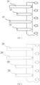
- the refrigerant in the first heat exchanger 20 flows in the first heat exchanger 20 from the first distributor 221, flows into the first flat tube 21 via the first capillary tube 222, then flows into the first collecting tube 231 via the first connecting tube 232 and then flows out from the first collecting tube 231 to define a first circulation path.
- the refrigerant in the second heat exchanger 30 flows in the second heat exchanger 30 from the second distributor 321, flows into the second flat tube 31 via the second capillary tube 322, then flows into the second collecting tube 331 via the second connecting tube 332 and then flows out from the second collecting tube 331 to define a second circulation path.
- the refrigerant in the first heat exchanger 20 flows in the first heat exchanger 20 from the first distributor 221, flows into the first flat tube 21 via the first capillary tube 222, bends via the first bending tube 40, flows into the first flat tube 21 in an adjacent row of first flat tubes 21, then flows into the first collecting tube 231 via the first connecting tube 232 and then flows out from the first collecting tube 231 to define a first circulation path.
- the refrigerant in the first heat exchanger 20 flows in the first heat exchanger 20 from the first distributor 221, flows into the first flat tube 21 via the first capillary tube 222, bends via the first bending tube 40, flows into the first flat tube 21 in the second row of first flat tubes 21, bends via the first bending tube 40, flows into the first flat tube 21 in the third row of first flat tubes 21, then flows into the first collecting tube 231 via the first connecting tube 232 and then flows out from the first collecting tube 231 to define a first circulation path.
- the second circulation path of the second heat exchanger 30 are the same, which is not limited herein.
- a group of the first circulation path and a group of the second circulation path and are isolated from one another the number of the first circulation path in the group of the first circulation path is defined as M , the number of the second circulation path in the group of the second circulation path is defined as N.
- each of the first circulation paths and each of the second circulation paths are disposed in turn and insulated from each other.
- the use ratio is the maximum with the circulation path arrangement.
- every two of the first circulation paths and every two of the second circulation paths are disposed in turns and insulated from each other.
- the number M of the first circulation path in the group of the first circulation path is equal to the number N of the second circulation path in the group of the second circulation path
- the number M of the first circulation path in the group of the first circulation path and the number N of the second circulation path in the group of the second circulation path can be any positive integer greater than 0, which are not illustrated herein.
- the circulation paths can be disposed in many ways, and the number M of the first circulation path in the group of the first circulation path can be not equal to the number N of the second circulation path in the group of the second circulation path.
- every two of the first circulation paths and each of the second circulation paths are disposed in turns and insulated from each other; optionally, each of the first circulation paths and every two of the second circulation paths are disposed in turns and insulated from each other; optionally, every three of the first circulation paths and every two of the second circulation paths are disposed in turns and insulated from each other, which are not limited herein.
- heat exchange intensity of the first heat exchanger 20 and the second heat exchanger 30 can be adjusted according to actual conditions, so as to change the heat exchange intensity at different positions of the microchannel heat exchanger group 100 and effectively control the specific heat exchange method of the microchannel heat exchanger group 100.
- the present application further provides a following technical solution.
- An air conditioning system which includes the microchannel heat exchanger group 100.
- the microchannel heat exchanger group 100 includes the same advantages with the air conditioning system.
- the microchannel heat exchanger group 100 since the microchannel heat exchanger group 100 further includes a first heat exchanger 20 and a second heat exchanger 30 independent of each other, when one of the first heat exchanger 20 and the second heat exchanger 30 is out of work, the other one of the first heat exchanger 20 and the second heat exchanger 30 can make full use of the heat exchange area of the plurality of fins 10 to exchange heat, thereby improving an energy efficiency of the microchannel heat exchanger group 100.
Landscapes
- Engineering & Computer Science (AREA)
- Physics & Mathematics (AREA)
- Mechanical Engineering (AREA)
- General Engineering & Computer Science (AREA)
- Thermal Sciences (AREA)
- Geometry (AREA)
- Chemical & Material Sciences (AREA)
- Combustion & Propulsion (AREA)
- Heat-Exchange Devices With Radiators And Conduit Assemblies (AREA)
Abstract
Description
- This application claims priority to
Chinese patent application No. 202221085342.4, filed on April 29, 2022 - The present application relates to the field of refrigeration, in particular, to a microchannel heat exchanger group and an air conditioning system having the same.
- Microchannel heat exchanger groups belong to a class of compact, lightweight and highly efficient heat exchangers designed to meet the needs of industrial development.
- In the related art, a refrigeration system usually needs a set of microchannel heat exchanger corresponding to the refrigeration system, which makes the heat exchange of the fins in the microchannel heat exchanger cannot be fully utilized, and thus reduces the heat exchange efficiency of the microchannel heat exchanger.
- A microchannel heat exchanger group capable of improving the thermal efficiency of the microchannel heat exchanger group and an air conditioning system including the same are provided on the basis of embodiments of the present application.
- In order to solve the technical problems above, the present application provides a following technical solution.
- A microchannel heat exchanger group, including a plurality of fins, wherein the plurality of fins are arranged in a plurality of rows, and each of the plurality of fins are provided with insertion slots; wherein the microchannel heat exchanger group further at least includes a first heat exchanger and a second heat exchanger, the first heat exchanger includes a plurality of first flat tubes, the second heat exchanger includes a plurality of second flat tubes, the plurality of first flat tubes and the plurality of second flat tubes are arranged in a plurality of layers along a length direction of each of the plurality of fins, the plurality of first flat tubes and the plurality of second flat tubes are arranged in a plurality of rows along a width direction of each of the plurality of fins; the insertion slots include a first insertion slot and a second insertion slot, the plurality of first flat tubes are inserted into the first insertion slot, the plurality of second flat tubes are inserted into the second insertion slot, and the plurality of first flat tubes are separated from the plurality of second flat tubes.
- It could be understood that in the present application, since the microchannel heat exchanger group further includes a first heat exchanger and a second heat exchanger independent of each other, when one of the first heat exchanger and the second heat exchanger is out of work, the other one of the first heat exchanger and the second heat exchanger can make full use of the heat exchange area of the plurality of fins to exchange heat, thereby improving an energy efficiency of the microchannel heat exchanger group.
- In some embodiments, the plurality of first flat tubes and the plurality of second flat tubes alternate with each other along the length direction of the plurality of fins.
- It could be understood that since the plurality of first flat tubes and the plurality of second flat tubes alternate with each other, when one of the first heat exchanger and the second heat exchanger is out of work, the other one of the first heat exchanger and the second heat exchanger can further make full use of the heat exchange area of the plurality of fins to exchange heat, thereby improving an energy efficiency of the microchannel heat exchanger group.
- In some embodiments, the first heat exchanger includes a first connector assembly and a second connector assembly, each of the plurality of first flat tubes, the first connector assembly and the second connector assembly are connected to and in communication with each other, a first circulation path is defined by a refrigerant flowing into one of the plurality of first flat tubes from the first connector assembly, and flowing out from the second connector assembly; and the second heat exchanger includes a third connector assembly and a fourth connector assembly, each of the plurality of second flat tubes, the third connector assembly and the fourth connector assembly are connected to and in communication with each other, a second circulation path is defined by the refrigerant flowing into one of the plurality of first flat tubes from the third connector assembly, and flowing out from the fourth connector assembly; wherein a group of the first circulation path and a group of the second circulation path and are isolated from one another, the number of the first circulation path in the group of the first circulation path is defined as M, the number of the second circulation path in the group of the second circulation path is defined as N, and both the number M of the first circulation path in the group of the first circulation path and the number N of the second circulation path in the group of the second circulation path are natural numbers equal to or greater than 1.
- In some embodiments, the number M of the first circulation path in the group of the first circulation path and the number N of the second circulation path in the group of the second circulation path satisfy the following formula: M = N.
- In some embodiments, the insertion slots are disposed at a same side of the plurality of fins, the insertion slots at adjacent rows of the plurality of fins alternate with each other; optionally wherein both sides of each of the plurality of fins are provided with the insertion slots, and the insertion slots disposed at both sides of each of the plurality of fins alternate with each other.
- It could be understood that since the insertion slots are alternatingly disposed, the contact area between the plurality of first flat tubes, the plurality of second flat tubes and the plurality of fins are improved, thereby improving the heat exchange efficiency of the microchannel heat exchanger group.
- In some embodiments, the first connector assembly includes a first distributor and a plurality of first capillary tubes being connected to and in communication with the first distributor, both ends of each of the plurality of first capillary tubes are connected to and in communication with the first distributor and corresponding one of the plurality of first flat tubes, respectively; and the third connector assembly includes a second distributor and a plurality of second capillary tubes being connected to and in communication with the second distributor, both ends of each of the plurality of second capillary tubes are connected to and in communication with the second distributor and corresponding one of the plurality of second flat tubes, respectively.
- It could be understood that by providing the first distributor and the second distributor, the refrigerant flows into the plurality of first flat tubes and the plurality of second flat tubes after the refrigerant is evenly distributed by the first distributor and the second distributor, and the processing is simplified.
- In some embodiments, the second connector assembly includes a first collecting tube and a plurality of first connecting tubes being connected to and in communication with the first collecting tube, both ends of each of the plurality of the first connecting tubes are connected to and in communication with the first collecting tube and corresponding one of the plurality of first flat tubes; and the fourth connector assembly includes a second collecting tube and a plurality of second connecting tubes being connected to and in communication with the second collecting tube, both ends of each of the plurality of the second connecting tubes are connected to and in communication with the second collecting tube and corresponding one of the plurality of second flat tubes.
- It could be understood that by disposing the first collecting tube and the second collecting tube, it is convenient to collect the refrigerant in the first flat tube and the second flat tube.
- In some embodiments, both the plurality of first flat tubes and the plurality of second flat tubes are arranged in a plurality of rows, the first heat exchanger includes a plurality of first bending tubes, the second heat exchanger comprises a plurality of second bending tubes, the first flat tubes arranged in adjacent rows of the plurality of first flat tubes are connected to and in communication with each other via corresponding one of the plurality of first bending tubes, and the plurality of first bending tubes and the plurality of first flat tubes are separately arranged; and the second flat tubes arranged in adjacent rows of the plurality of second flat tubes are connected to and in communication with each other via corresponding one of the plurality of second bending tubes, and the plurality of second bending tubes and the plurality of second flat tubes are separately arranged.
- It could be understood that since the microchannel heat exchanger group includes a plurality of first bending tubes and a plurality of second bending tubes, the refrigerant can make a turn, and deformation of the plurality of fins caused by bending of the plurality of fins can be avoided.
- In some embodiments, the microchannel heat exchanger group further includes an adapter, the adapter is disposed between the plurality of first capillary tubes and the plurality of first flat tubes and between the plurality of second capillary tubes and the plurality of second flat tubes, and a tube orifice of the adapter opposite to the plurality of first flat tubes matches with a tube orifice of corresponding one of the plurality of first flat tube and another tube orifice of the adapter opposite the plurality of second flat tubes matches with a tube orifice of corresponding one of the plurality of second flat tube.
- It could be understood that by disposing the adapter, it is convenient for matching and connection between the plurality of the capillary tubes and the plurality of the flat tubes.
- The present application further provides the following technical solution. An air conditioning system is provided, which includes a microchannel heat exchanger group.
- In comparison with related art, in the present application, since the microchannel heat exchanger group further includes a first heat exchanger and a second heat exchanger independent of each other, when one of the first heat exchanger and the second heat exchanger is out of work, the other one of the first heat exchanger and the second heat exchanger can make full use of the heat exchange area of the plurality of fins to exchange heat, thereby improving an energy efficiency of the microchannel heat exchanger group.
- In order to more clearly illustrate the technical solutions in the embodiments of the present application or in the conventional technology, the accompanying drawings to be used in the description of the embodiments or the conventional technology will be briefly described below. Obviously, the accompanying drawings in the following description are only some of the embodiments of the present application, and other accompanying drawings may be obtained from these drawings without creative labor for a person of ordinary skill in the art.
-
FIG. 1 is a structural schematic diagram of a microchannel heat exchanger group provided in the present application from an angle of view. -
FIG. 2 is a structural schematic diagram of a microchannel heat exchanger group provided in the present application from an angle of view. -
FIG. 3 is a structural schematic diagram of a circulation path of the microchannel heat exchanger group in an embodiment of the present application. -
FIG. 4 is a structural schematic diagram of a circulation path of the microchannel heat exchanger group in an embodiment of the present application. -
FIG. 5 is a structural schematic diagram of an air conditioning system including a microchannel heat exchanger group provided in the present application. - In the figures, 100 represents a microchannel heat exchanger group; 10 represents a fin; 11 represents an insertion slot; 111 represents a first insertion slot; 112 represents a second insertion slot; 20 represents a first heat exchanger; 21 represents a first flat tube; 22 represents a first connector assembly; 221 represents a first distributor; 222 represents a first capillary tube; 23 represents a second connector assembly; 231 represents a first collecting tube; 232 represents a first connecting tube; 30 represents a second heat exchanger; 31 represents a second flat tube; 32 represents a third connector assembly; 321 represents a second distributor; 322 represents a second capillary tube; 33 represents a fourth connector assembly; 331 represents a second collecting tube; 332 represents a second connecting tube; 40 represents a first bending tube; 41 represents a second bending tube; 50 represents an adapter; and 200 represents an air conditioning system.
- The technical solutions in the embodiments of the present application will be described clearly and completely in the following in conjunction with the accompanying drawings in the embodiments of the present application, and it is obvious that the described embodiments are only a part of the embodiments of the present application, but not all of the embodiments. Based on the embodiments in this application, all other embodiments obtained by a person of ordinary skill in the art without making creative labor fall within the scope of protection of this application.
- It is noted that when a component is said to be "fixed to" or "disposed on" another component, it may be directly on the other component or there may be a centred component. When a component is said to be "connected" to another component, it may be directly connected to the other component or there may be both centred components. The terms "vertical", "horizontal", "up", "down", "left", "right" and similar expressions used in the specification of the present application are for illustrative purposes only and are not meant to be exclusive.
- Furthermore, the terms "first", "second" are used for descriptive purposes only and are not to be understood as indicating or implying relative importance or implicitly specifying the number of technical features indicated. Thus, a feature defined with the terms "first", "second" may include at least one such feature, either explicitly or implicitly. In the description of the present application, "plurality" means at least two, e.g., two, three, etc., unless otherwise expressly and specifically limited.
- In the present application, unless otherwise expressly specified and limited, the first feature "on" or "under" the second feature may be that the first feature is in direct contact with the second feature, or that the first feature is in indirect contact with the second feature through an intermediate medium. Furthermore, the first feature being "above", "on" or "upon" the second feature may mean that the first feature is directly above or diagonally above the second feature, or it may simply mean that the first feature is horizontally higher than the second feature. The first feature being "below", "under" or "beneath" the second feature may be that the first feature is directly below or diagonally below the second feature, or it may simply mean that the first feature is horizontally smaller than the second feature.
- Unless otherwise defined, all technical and scientific terms used in the specification of the present application have the same meaning as commonly understood by those skilled in the art to which the present application belongs. Terms used in the specification of the present application are used only for the purpose of describing specific embodiments and are not intended to limit the present application. The term "and/or" as used in the specification of the present application includes any and all combinations of one or more of the relevant listed items.
- Referring to
FIG.1 to FIG.4 , a microchannelheat exchanger group 100 is provided in the present application, which is disposed in the air conditioning system. A medium flows in the microchannelheat exchanger group 100, and the microchannelheat exchanger group 100 can facilitate heat exchange between the medium and the outside world. - In the related art, a refrigeration system usually needs a set of microchannel heat exchanger corresponding to the refrigeration system, which makes the heat exchange of the fins in the microchannel heat exchanger cannot be fully utilized, and thus reduces the heat exchange efficiency of the microchannel heat exchanger.
- In order to solve the problems of the microchannel heat exchanger group in the related art, a microchannel
heat exchanger group 100 is provided in the present application. The microchannelheat exchanger group 100 includes a plurality offins 10, wherein the plurality offins 10 are arranged in a plurality of rows, each of the plurality offins 10 are provided withinsertion slots 11, and a firstflat tube 21 and a secondflat tube 31 extends in theinsertion slots 11. The microchannelheat exchanger group 100 further includes at least afirst heat exchanger 20 and asecond heat exchanger 30 independent of thefirst heat exchanger 20. Thefirst heat exchanger 20 includes a plurality of firstflat tubes 21, and thesecond heat exchanger 30 includes a plurality of secondflat tubes 31. The plurality of firstflat tubes 21 and the plurality of secondflat tubes 31 are arranged in a plurality of layers along a length direction of each of the plurality offins 10, and the plurality of firstflat tubes 21 and the plurality of secondflat tubes 31 are arranged in a plurality of rows along a width direction of each of the plurality offins 10. Theinsertion slots 11 include afirst insertion slot 111 and asecond insertion slot 112, the plurality of firstflat tubes 21 are inserted into thefirst insertion slot 111, and the plurality of secondflat tubes 31 are inserted into thesecond insertion slot 112. The plurality of firstflat tubes 21 are separated from the plurality of secondflat tubes 31, and plurality of firstflat tubes 21 are not in communication with the plurality of secondflat tubes 31. - It should be noted that in the present application, the microchannel
heat exchanger group 100 includes at least two heat exchangers. Arrangement of at least two heat exchangers independent of each other in the same set offins 10 of the heat exchanger have following advantages. In one aspect, operation of each of the heat exchangers can be controlled according to actual conditions, so that compatibility performances of the microchannelheat exchanger group 100 can be improved; in another aspect, when one of thefirst heat exchanger 20 and thesecond heat exchanger 30 is out of work, the other one of thefirst heat exchanger 20 and thesecond heat exchanger 30 can make full use of the heat exchange area of the plurality offins 10 to exchange heat, thereby improving an energy efficiency of the microchannel heat exchanger group. - It should be noted that in the present application, the plurality of
fins 10 extend along a vertical direction, and the plurality offins 10 are parallelly arranged in a plurality of rows. The plurality of firstflat tubes 21 and the plurality of secondflat tubes 31 extend along a horizontal direction. In addition, along the vertical direction, the plurality of firstflat tubes 21 and the plurality of secondflat tubes 31 are successively arranged and arranged in a plurality of layers. Then, the plurality of layers of firstflat tubes 21 and the plurality of layers of secondflat tubes 31 are arranged along the horizontal direction in a plurality of rows. The plurality of firstflat tubes 21 and the plurality of secondflat tubes 31 are arranged in a plurality of layers and a plurality of rows. Thus, the structure of the microchannelheat exchanger group 100 is more compact and the heat exchange efficiency of the microchannelheat exchanger group 100 is improved. - In the present embodiment, that the microchannel
heat exchanger group 100 at least includes afirst heat exchanger 20 and asecond heat exchanger 30 indicates that the microchannelheat exchanger group 100 at least includes two independent heat exchangers. In some embodiments, the microchannelheat exchanger group 100 can further include a third heat exchanger, a fourth heat exchanger, a fifth heat exchanger and even more heat exchangers, which are not limited herein. In the present application, amicrochannel heat exchanger 100 is taken as an example. - Referring to
FIG. 1 , each of the plurality offins 10 extends along the vertical direction, the plurality offins 10 are parallelly arranged along the horizontal direction in a plurality of rows. Theinsertion slots 11 are disposed at the same side of thefins 10 in each row of the plurality of rows of thefins 10, and theinsertion slots 10 in adjacent rows of the plurality of rows ofins 10 are staggered, so that the contact area between the flat tube and thefin 10 is great, improving the heat exchange efficiency of theheat exchanger group 100. - In some embodiments, both sides of each of the plurality of rows of fins are provided with the
insertion slots 11, and theinsertion slots 11 at both sides of each of the plurality offins 10 are staggered. The flat tubes extend through each of the staggeredinsertion slots 11. The flat tubes extend along the horizontal direction. Since the flat tubes are staggered, the contact area between the flat tubes and the air is greater, so that the heat exchange efficiency of the microchannelheat exchanger group 100 is improved. - Referring to
FIG. 2 , thefirst heat exchanger 20 includes afirst connector assembly 22 and asecond connector assembly 23. Thefirst connector assembly 22 includes afirst distributor 221 and a plurality of firstcapillary tubes 222 being connected to and in communication with thefirst distributor 221. Both ends of each of the plurality of firstcapillary tubes 222 are connected to and in communication with thefirst distributor 221 and corresponding one of the plurality of firstflat tubes 21, respectively. The refrigerant in thefirst distributor 221 are distributed into each of the plurality of firstflat tubes 21 via the plurality of firstcapillary tubes 222. That is, the refrigerant flows into thefirst distributor 221 from an end of thefirst distributor 221 away from the firstcapillary tube 222. Since an outlet of thefirst distributor 221 is provided with a plurality of small holes being connected to and in communication with the plurality of firstcapillary tubes 222, an end of each of the plurality of firstcapillary tubes 222 are correspondingly connected to and in communication with each of the small holes of the outlet of the first distributor 211, and the other end of each of the plurality of firstcapillary tubes 222 are correspondingly connected to and in communication with each of the plurality of firstflat tubes 21 of the microchannelheat exchanger group 100. The refrigerant flows into each of the plurality of firstflat tubes 21 via each of the plurality of firstcapillary tubes 222, so that the refrigerant is distributed into each of the plurality of firstcapillary tubes 222 more evenly. - The
second connector assembly 23 includes afirst collecting tube 231 and a plurality of first connectingtubes 232 being connected to and in communication with thefirst collecting tube 231. Both ends of each of the plurality of the first connectingtubes 232 are connected to and in communication with thefirst collecting tube 231 and corresponding one of the plurality of firstflat tubes 21. The refrigerant in the plurality of firstflat tubes 21 are gathered in thefirst collecting tube 231 via the plurality of first connectingtubes 232. That is, thefirst collecting tube 231 is provided with a plurality of flowing holes configured for communicating the first connectingtubes 232. An end of each of the plurality of first connectingtubes 232 are connected to and in communication with each of the plurality of flowing holes on thefirst collecting tubes 231, respectively; and the other end of each of the plurality of first connectingtubes 232 are connected to and in communication with each of the plurality of firstflat tubes 21 of themicrochannel heat exchanger 100, respectively. The refrigerant flows into each of the plurality of firstflat tubes 21 via each of the plurality of firstcapillary tubes 222, and then flows into each of the plurality of first connectingtubes 232, and the flows into and gathers in thefirst collecting tube 231 from the plurality of first connectingtubes 232, and then entirely flows out from thefirst collecting tube 231. Therefore, a heat exchange circulation process in thefirst heat exchanger 20 is accomplished. - The
second heat exchanger 30 includes athird connector assembly 32 and afourth connector assembly 33. Thethird connector assembly 32 includes asecond distributor 321 and a plurality of secondcapillary tubes 322 being connected to and in communication with thesecond distributor 321. Both ends of each of the plurality of secondcapillary tubes 322 are connected to and in communication with thesecond distributor 321 and corresponding one of the plurality of secondflat tubes 31, respectively. The refrigerant in thesecond distributor 321 are distributed into each of the plurality of secondflat tubes 31 via the plurality of secondcapillary tubes 322. That is, the refrigerant flows into thesecond distributor 321 from an end of thesecond distributor 321 away from the secondcapillary tube 322. Since an outlet of thesecond distributor 321 is provided with a plurality of small holes being connected to and in communication with the plurality of secondcapillary tubes 322, an end of each of the plurality of secondcapillary tubes 322 are correspondingly connected to and in communication with each of the small holes of the outlet of thesecond distributor 321, and the other end of each of the plurality of secondcapillary tubes 322 are correspondingly connected to and in communication with each of the plurality of secondflat tubes 31 of the microchannelheat exchanger group 100. The refrigerant flows into each of the plurality of secondflat tubes 31 via each of the plurality of secondcapillary tubes 322, so that the refrigerant is distributed into each of the plurality of secondcapillary tubes 322 more evenly. - The
fourth connector assembly 33 includes asecond collecting tube 331 and a plurality of second connectingtubes 332 being connected to and in communication with thesecond collecting tube 331. Both ends of each of the plurality of the second connectingtubes 332 are connected to and in communication with thesecond collecting tube 331 and corresponding one of the plurality of secondflat tubes 31. The refrigerant in the plurality of secondflat tubes 31 are gathered in thesecond collecting tube 331 via the plurality of second connectingtubes 332. That is, thesecond collecting tube 331 is provided with a plurality of flowing holes configured for communicating the second connectingtubes 332. An end of each of the plurality of second connectingtubes 332 are connected to and in communication with each of the plurality of flowing holes on thesecond collecting tubes 331, respectively; and the other end of each of the plurality of second connectingtubes 332 are connected to and in communication with each of the plurality of secondflat tubes 31 of themicrochannel heat exchanger 100, respectively. The refrigerant flows into each of the plurality of secondflat tubes 31 via each of the plurality of secondcapillary tubes 322, and then flows into each of the plurality of second connectingtubes 332, and the flows into and gathers in thesecond collecting tube 331 from the plurality of second connectingtubes 332, and then entirely flows out from thesecond collecting tube 331. Therefore, a heat exchange circulation process in thesecond heat exchanger 30 is accomplished. - In some embodiments, the plurality of first
flat tubes 21 and the plurality of secondflat tubes 31 alternate with each other and separated from each other. In this way, when one of thefirst heat exchanger 20 and thesecond heat exchanger 30 is out of work, the other one of thefirst heat exchanger 20 and thesecond heat exchanger 30 can make full use of the heat exchange area of the plurality offins 10 to exchange heat, thereby improving an energy efficiency of the microchannelheat exchanger group 100. It should be noted that when all of the firstflat tubes 21 are parallelly arranged in an upper section of the microchannelheat exchanger group 100, all of the secondflat tubes 31 are correspondingly arranged in a lower section of the microchannelheat exchanger group 100; optionally, when all of the firstflat tubes 21 are parallelly arranged in the lower section of the microchannelheat exchanger group 100, all of the secondflat tubes 31 are correspondingly arranged in the upper section of the microchannelheat exchanger group 100. Therefore, when one of thefirst heat exchanger 20 and thesecond heat exchanger 30 is out of work, the firstflat tube 21 or the secondflat tube 31 can only make use of a half of the area of thefins 10 in the microchannelheat exchanger group 100 to exchange heat. In comparison to the method in which the firstflat tubes 21 and the secondflat tubes 31 alternate in the microchannelheat exchanger group 100, it is obvious that the method in which the firstflat tubes 21 and the secondflat tubes 31 alternate with each other can make best use of the heat change area of thefins 10, thereby improving the energy efficiency of the microchannelheat exchanger group 100. - In some embodiments, microchannel
heat exchanger group 100 includes at least two rows of the firstflat tubes 21 and at least two rows of the secondflat tubes 31. The microchannelheat exchanger group 100 can further include a plurality offirst bending tubes 40 and a plurality ofsecond bending tubes 41. The firstflat tubes 21 arranged in adjacent rows of the plurality of firstflat tubes 21 are connected to and in communication with each other via corresponding one of the plurality offirst bending tubes 40, and the plurality offirst bending tubes 40 are independent of the plurality of firstflat tubes 21; and the secondflat tubes 31 arranged in adjacent rows of the plurality of secondflat tubes 31 are connected to and in communication with each other via corresponding one of the plurality ofsecond bending tubes 41, and the plurality ofsecond bending tubes 41 are independent of the plurality of secondflat tubes 31. - It should be noted that in the microchannel heat exchanger group in the related art, the fins are arranged in a plurality of rows by bending the fins, which may cause deformation of the fins in the bending process and affect the heat exchange efficiency. Therefore, in order to solve the problem described above, adjacent flat tubes are connected to and in communication with each other via the bending tubes in the present application, so that the refrigerant can make a turn, and deformation of the plurality of
fins 10 caused by bending of the plurality offins 10 can be avoided. - In some embodiments, the microchannel
heat exchanger group 100 further includes anadapter 50, theadapter 50 is disposed between the plurality of firstcapillary tubes 222 and the plurality of firstflat tubes 21 and between the plurality of secondcapillary tubes 332 and the plurality of secondflat tubes 31. In one aspect, since the firstcapillary tube 222 and the secondcapillary tube 322 are thin and has circular-shaped across section, and the cross section of the firstflat tube 21 and the cross section of the secondflat tube 31 are stripe-shaped, the cross section of the firstcapillary tube 222 and the cross section of thesection capillary tube 322 cannot directly match with and connect to the cross section of the first flat tube and the cross section of the secondflat tube 31, and transition of theadapter 50 is required to accomplish the communication between the plurality of firstcapillary tubes 222 and the plurality of firstflat tubes 21 and between the plurality of secondcapillary tubes 332 and the plurality of secondflat tubes 31. An end of theadapter 50 adjacent to the firstcapillary tube 222 or the secondcapillary tube 322 are set as circular-shaped matching with the capillary tubes, and an end of the adapter adjacent to the firstflat tube 21 or the secondflat tube 31 are set as stripe-shaped matching with the flat tubes. In another aspect, a plurality of flowing channels are generally disposed in the flat tubes to increase the heat exchange area, but only one flowing channel is disposed in the capillary tubes. Thus, transition of theadapter 50 is required to accomplish communication between the only one flowing channel in the capillary tubes and the plurality of flowing channels in the flat tube. - Specifically, the refrigerant in the
first heat exchanger 20 flows in thefirst heat exchanger 20 from thefirst distributor 221, flows into the firstflat tube 21 via the firstcapillary tube 222, then flows into thefirst collecting tube 231 via the first connectingtube 232 and then flows out from thefirst collecting tube 231 to define a first circulation path. The refrigerant in thesecond heat exchanger 30 flows in thesecond heat exchanger 30 from thesecond distributor 321, flows into the secondflat tube 31 via the secondcapillary tube 322, then flows into thesecond collecting tube 331 via the second connectingtube 332 and then flows out from thesecond collecting tube 331 to define a second circulation path. It should be noted that when the heat exchanger group includes two rows of firstflat tubes 21, the refrigerant in thefirst heat exchanger 20 flows in thefirst heat exchanger 20 from thefirst distributor 221, flows into the firstflat tube 21 via the firstcapillary tube 222, bends via thefirst bending tube 40, flows into the firstflat tube 21 in an adjacent row of firstflat tubes 21, then flows into thefirst collecting tube 231 via the first connectingtube 232 and then flows out from thefirst collecting tube 231 to define a first circulation path. When the heat exchanger group includes three rows of firstflat tubes 21, both ends of the firstflat tube 21 and the secondflat tube 31 are provided with thefirst bending tube 40 and thesecond bending tube 41, the refrigerant in thefirst heat exchanger 20 flows in thefirst heat exchanger 20 from thefirst distributor 221, flows into the firstflat tube 21 via the firstcapillary tube 222, bends via thefirst bending tube 40, flows into the firstflat tube 21 in the second row of firstflat tubes 21, bends via thefirst bending tube 40, flows into the firstflat tube 21 in the third row of firstflat tubes 21, then flows into thefirst collecting tube 231 via the first connectingtube 232 and then flows out from thefirst collecting tube 231 to define a first circulation path. The second circulation path of thesecond heat exchanger 30 are the same, which is not limited herein. - In some embodiments, a group of the first circulation path and a group of the second circulation path and are isolated from one another, the number of the first circulation path in the group of the first circulation path is defined as M, the number of the second circulation path in the group of the second circulation path is defined as N.
- In some embodiments, the number M of the first circulation path in the group of the first circulation path and the number N of the second circulation path in the group of the second circulation path satisfy the following formula: M = N.
- Referring to
FIG. 3 , when the number M of the first circulation path in the group of the first circulation path is equal to the number N of the second circulation path in the group of the second circulation path. In some embodiments, each of the first circulation paths and each of the second circulation paths are disposed in turn and insulated from each other. For use ratio offins 10 of each of the heat exchanger, the use ratio is the maximum with the circulation path arrangement. - Referring to
FIG. 4 , when the number M of the first circulation path in the group of the first circulation path is equal to the number N of the second circulation path in the group of the second circulation path, in some embodiments, every two of the first circulation paths and every two of the second circulation paths are disposed in turns and insulated from each other. - When the number M of the first circulation path in the group of the first circulation path is equal to the number N of the second circulation path in the group of the second circulation path, in some embodiments, the number M of the first circulation path in the group of the first circulation path and the number N of the second circulation path in the group of the second circulation path can be any positive integer greater than 0, which are not illustrated herein.
- The circulation paths can be disposed in many ways, and the number M of the first circulation path in the group of the first circulation path can be not equal to the number N of the second circulation path in the group of the second circulation path. For example, every two of the first circulation paths and each of the second circulation paths are disposed in turns and insulated from each other; optionally, each of the first circulation paths and every two of the second circulation paths are disposed in turns and insulated from each other; optionally, every three of the first circulation paths and every two of the second circulation paths are disposed in turns and insulated from each other, which are not limited herein. By adjusting the arrangement method of the circulation paths, heat exchange intensity of the
first heat exchanger 20 and thesecond heat exchanger 30 can be adjusted according to actual conditions, so as to change the heat exchange intensity at different positions of the microchannelheat exchanger group 100 and effectively control the specific heat exchange method of the microchannelheat exchanger group 100. - The present application further provides a following technical solution.
- An air conditioning system, which includes the microchannel
heat exchanger group 100. The microchannelheat exchanger group 100 includes the same advantages with the air conditioning system. - In the microchannel
heat exchanger group 100 provided in the present application, since the microchannelheat exchanger group 100 further includes afirst heat exchanger 20 and asecond heat exchanger 30 independent of each other, when one of thefirst heat exchanger 20 and thesecond heat exchanger 30 is out of work, the other one of thefirst heat exchanger 20 and thesecond heat exchanger 30 can make full use of the heat exchange area of the plurality offins 10 to exchange heat, thereby improving an energy efficiency of the microchannelheat exchanger group 100. - The technical features of the above-mentioned embodiments can be combined arbitrarily. In order to make the description concise, not all possible combinations of the technical features are described in the embodiments. However, as long as there is no contradiction in the combination of these technical features, the combinations should be considered as in the scope of the present application.
- The above-described embodiments are only several implementations of the present application, and the descriptions are relatively specific and detailed, but they should not be construed as limiting the scope of the present application. It should be understood by those of ordinary skill in the art that various modifications and improvements can be made without departing from the concept of the present application, and all fall within the protection scope of the present application. Therefore, the patent protection of the present application shall be defined by the appended claims.
Claims (10)
- A microchannel heat exchanger group, comprisinga plurality of fins, wherein the plurality of fins are arranged in a plurality of rows, and each of the plurality of fins are provided with insertion slots;characterized in that the microchannel heat exchanger group further at least comprises a first heat exchanger and a second heat exchanger, the first heat exchanger comprises a plurality of first flat tubes, the second heat exchanger comprises a plurality of second flat tubes, the plurality of first flat tubes and the plurality of second flat tubes are arranged in a plurality of layers along a length direction of each of the plurality of fins, the plurality of first flat tubes and the plurality of second flat tubes are arranged in a plurality of rows along a width direction of each of the plurality of fins; andthe insertion slots comprise a first insertion slot and a second insertion slot, the plurality of first flat tubes are inserted into the first insertion slot, the plurality of second flat tubes are inserted into the second insertion slot, and the plurality of first flat tubes are separated from the plurality of second flat tubes.
- The microchannel heat exchanger of claim 1, wherein the plurality of first flat tubes and the plurality of second flat tubes alternate with each other along the length direction of the plurality of fins.
- The microchannel heat exchanger group of claim 2, wherein the first heat exchanger comprises a first connector assembly and a second connector assembly,each of the plurality of first flat tubes, the first connector assembly and the second connector assembly are connected to and in communication with each other, a first circulation path is defined by a refrigerant flowing into one of the plurality of first flat tubes from the first connector assembly, and flowing out from the second connector assembly; andthe second heat exchanger comprises a third connector assembly and a fourth connector assembly, each of the plurality of second flat tubes, the third connector assembly and the fourth connector assembly are connected to and in communication with each other, a second circulation path is defined by the refrigerant flowing into one of the plurality of first flat tubes from the third connector assembly, and flowing out from the fourth connector assembly;wherein a group of the first circulation path and a group of the second circulation path and are isolated from one another, the number of the first circulation path in the group of the first circulation path is defined as M, the number of the second circulation path in the group of the second circulation path is defined as N, and both the number M of the first circulation path in the group of the first circulation path and the number N of the second circulation path in the group of the second circulation path are natural numbers equal to or greater than 1.
- The microchannel heat exchanger group of claim 3, wherein the number M of the first circulation path in the group of the first circulation path and the number N of the second circulation path in the group of the second circulation path satisfy a following formula: M = N.
- The microchannel heat exchanger group of claim 1, wherein the insertion slots are disposed at a same side of the plurality of fins, the insertion slots at adjacent rows of the plurality of fins alternate with each other; optionally wherein
both sides of each of the plurality of fins are provided with the insertion slots, and the insertion slots disposed at both sides of each of the plurality of fins alternate with each other. - The microchannel heat exchanger group of claim 3, wherein the first connector assembly comprises a first distributor and a plurality of first capillary tubes being connected to and in communication with the first distributor, both ends of each of the plurality of first capillary tubes are connected to and in communication with the first distributor and corresponding one of the plurality of first flat tubes, respectively; and
the third connector assembly comprises a second distributor and a plurality of second capillary tubes being connected to and in communication with the second distributor, both ends of each of the plurality of second capillary tubes are connected to and in communication with the second distributor and corresponding one of the plurality of second flat tubes, respectively. - The microchannel heat exchanger group of claim 6, wherein the second connector assembly comprises a first collecting tube and a plurality of first connecting tubes being connected to and in communication with the first collecting tube, both ends of each of the plurality of the first connecting tubes are connected to and in communication with the first collecting tube and corresponding one of the plurality of first flat tubes; and
the fourth connector assembly comprises a second collecting tube and a plurality of second connecting tubes being connected to and in communication with the second collecting tube, both ends of each of the plurality of the second connecting tubes are connected to and in communication with the second collecting tube and corresponding one of the plurality of second flat tubes. - The microchannel heat exchanger group of claim 1, wherein both the plurality of first flat tubes and the plurality of second flat tubes are arranged in a plurality of rows, the first heat exchanger comprises a plurality of first bending tubes, the second heat exchanger comprises a plurality of second bending tubes, the first flat tubes arranged in adjacent rows of the plurality of first flat tubes are connected to and in communication with each other via corresponding one of the plurality of first bending tubes, and the plurality of first bending tubes and the plurality of first flat tubes are separately arranged; and the second flat tubes arranged in adjacent rows of the plurality of second flat tubes are connected to and in communication with each other via corresponding one of the plurality of second bending tubes, and the plurality of second bending tubes and the plurality of second flat tubes are separately arranged.
- The microchannel heat exchanger group of claim 6, further comprising an adapter, the adapter is disposed between the plurality of first capillary tubes and the plurality of first flat tubes and between the plurality of second capillary tubes and the plurality of second flat tubes, and a tube orifice of the adapter opposite to the plurality of first flat tubes matches with a tube orifice of corresponding one of the plurality of first flat tube and another tube orifice of the adapter opposite to the plurality of second flat tubes matches with a tube orifice of corresponding one of the plurality of second flat tube.
- An air conditioning system, characterized by comprising the microchannel heat exchanger group of claims 1 to 9.
Applications Claiming Priority (2)
| Application Number | Priority Date | Filing Date | Title |
|---|---|---|---|
| CN202221085342.4U CN217464958U (en) | 2022-04-29 | 2022-04-29 | Microchannel heat exchanger group and air conditioning system having the same |
| PCT/CN2023/091268 WO2023208129A1 (en) | 2022-04-29 | 2023-04-27 | Microchannel heat exchanger group and air conditioning system having same |
Publications (2)
| Publication Number | Publication Date |
|---|---|
| EP4517221A1 true EP4517221A1 (en) | 2025-03-05 |
| EP4517221A4 EP4517221A4 (en) | 2025-07-30 |
Family
ID=83273566
Family Applications (1)
| Application Number | Title | Priority Date | Filing Date |
|---|---|---|---|
| EP23795561.2A Pending EP4517221A4 (en) | 2022-04-29 | 2023-04-27 | Microchannel heat exchanger group and air conditioning system having same |
Country Status (4)
| Country | Link |
|---|---|
| US (1) | US20250052520A1 (en) |
| EP (1) | EP4517221A4 (en) |
| CN (1) | CN217464958U (en) |
| WO (1) | WO2023208129A1 (en) |
Families Citing this family (1)
| Publication number | Priority date | Publication date | Assignee | Title |
|---|---|---|---|---|
| CN217464958U (en) * | 2022-04-29 | 2022-09-20 | 浙江盾安热工科技有限公司 | Microchannel heat exchanger group and air conditioning system having the same |
Family Cites Families (7)
| Publication number | Priority date | Publication date | Assignee | Title |
|---|---|---|---|---|
| JP5195733B2 (en) * | 2009-12-17 | 2013-05-15 | 三菱電機株式会社 | Heat exchanger and refrigeration cycle apparatus equipped with the same |
| GB2561098B (en) * | 2015-12-25 | 2021-08-04 | Mitsubishi Electric Corp | Heat exchanger, air-conditioning apparatus including the same, and method of producing flat-tube u-bend |
| CN111520934A (en) * | 2020-05-18 | 2020-08-11 | 浙江盾安热工科技有限公司 | Heat exchanger and air conditioner with same |
| CN215114092U (en) * | 2021-05-31 | 2021-12-10 | 浙江盾安热工科技有限公司 | Heat exchanger |
| CN215766688U (en) * | 2021-05-31 | 2022-02-08 | 浙江盾安热工科技有限公司 | Connecting pipe and heat exchanger with same |
| CN215984104U (en) * | 2021-06-17 | 2022-03-08 | 浙江盾安热工科技有限公司 | Heat exchanger |
| CN217464958U (en) * | 2022-04-29 | 2022-09-20 | 浙江盾安热工科技有限公司 | Microchannel heat exchanger group and air conditioning system having the same |
-
2022
- 2022-04-29 CN CN202221085342.4U patent/CN217464958U/en active Active
-
2023
- 2023-04-27 EP EP23795561.2A patent/EP4517221A4/en active Pending
- 2023-04-27 WO PCT/CN2023/091268 patent/WO2023208129A1/en not_active Ceased
-
2024
- 2024-10-29 US US18/929,650 patent/US20250052520A1/en active Pending
Also Published As
| Publication number | Publication date |
|---|---|
| US20250052520A1 (en) | 2025-02-13 |
| WO2023208129A1 (en) | 2023-11-02 |
| CN217464958U (en) | 2022-09-20 |
| EP4517221A4 (en) | 2025-07-30 |
Similar Documents
| Publication | Publication Date | Title |
|---|---|---|
| US11815318B2 (en) | Flattened tube finned heat exchanger and fabrication method | |
| EP2972037B1 (en) | Heat exchanger for air-cooled chiller | |
| EP2948724B1 (en) | Multiple tube bank heat exchange unit with manifold assembly | |
| US6286590B1 (en) | Heat exchanger with flat tubes of two columns | |
| EP2810010B1 (en) | Multiple tube bank heat exchanger assembly and fabrication method | |
| US20230366637A1 (en) | Microchannel flat tube and microchannel heat exchanger | |
| AU2017206116B2 (en) | Improvement of thermal capacity of elliptically finned heat exchanger | |
| JP3110196U (en) | Thin tube heat exchanger | |
| JPH03177795A (en) | Double system integrated type heat exchanger | |
| US9901966B2 (en) | Method for fabricating flattened tube finned heat exchanger | |
| CN103608639B (en) | Fin tube heat exchanger | |
| US20250052520A1 (en) | Microchannel heat exchanger group and air conditioning system having same | |
| EP2956728B1 (en) | Multiple bank flattened tube heat exchanger | |
| CN105783338A (en) | Heat exchanger | |
| US20160054075A1 (en) | Folded tube multiple bank heat exchange unit | |
| KR20050084778A (en) | Heat exchanger | |
| EP4431856A1 (en) | Micro-channel heat exchanger and heat pump system having the same | |
| US12044479B2 (en) | Heat exchanger | |
| CN210128532U (en) | Multi-refrigeration system air conditioning unit | |
| CN217358209U (en) | Hairpin pipe, heat exchange structure and air conditioner | |
| CN214747458U (en) | Heat exchange fin, heat exchanger and air conditioner | |
| CN211739946U (en) | Micro-channel parallel flow heat exchanger | |
| JP3107159B2 (en) | cooling tower | |
| JPH03194370A (en) | Heat exchanger for air conditioner | |
| CN211146969U (en) | Heat exchanger |
Legal Events
| Date | Code | Title | Description |
|---|---|---|---|
| STAA | Information on the status of an ep patent application or granted ep patent |
Free format text: STATUS: THE INTERNATIONAL PUBLICATION HAS BEEN MADE |
|
| PUAI | Public reference made under article 153(3) epc to a published international application that has entered the european phase |
Free format text: ORIGINAL CODE: 0009012 |
|
| STAA | Information on the status of an ep patent application or granted ep patent |
Free format text: STATUS: REQUEST FOR EXAMINATION WAS MADE |
|
| 17P | Request for examination filed |
Effective date: 20241031 |
|
| AK | Designated contracting states |
Kind code of ref document: A1 Designated state(s): AL AT BE BG CH CY CZ DE DK EE ES FI FR GB GR HR HU IE IS IT LI LT LU LV MC ME MK MT NL NO PL PT RO RS SE SI SK SM TR |
|
| A4 | Supplementary search report drawn up and despatched |
Effective date: 20250702 |
|
| RIC1 | Information provided on ipc code assigned before grant |
Ipc: F25B 39/00 20060101AFI20250626BHEP Ipc: F28F 9/26 20060101ALI20250626BHEP Ipc: F24F 13/30 20060101ALI20250626BHEP |
|
| DAV | Request for validation of the european patent (deleted) | ||
| DAX | Request for extension of the european patent (deleted) |