-
Die vorliegende Erfindung betrifft eine Dunstabzugshaube mit einer Beleuchtungsvorrichtung.
-
Es ist bekannt eine "atmosphärische" Beleuchtung, die auch als Stimmungslicht oder Moodlight bezeichnet werden kann, an einer Dunstabzugshaube vorzusehen. Hierbei wird insbesondere die Wand, an der die Dunstabzugshaube befestigt ist, über Beleuchtungselemente, die beispielsweise an der Rückseite der Dunstabzugshaube vorgesehen sein können, beleuchtet. Hierdurch wird eine indirekte Beleuchtung des Raums erzeugt.
-
Zudem ist es bekannt bei einer Dunstabzugshaube mit Schirmvorrichtung mit Ansaugfenster und einer Dekoreinrichtung, die das Ansaugfenster abdeckt, an dem Ansaugfenster ein Beleuchtungsmodul vorzusehen. Das Beleuchtungsmodul umfasst dazu mehrere Beleuchtungsgruppen mit jeweils einem Leuchtmittel, die unterschiedliche Beleuchtungsmethoden zur Verfügung stellen. Eine solche Dunstabzugshaube ist in der
DE 10 2015 101 099 B4 beschrieben.
-
Ein Nachteil des Standes der Technik besteht darin, dass das von dem jeweiligen Beleuchtungselement beziehungsweise der Beleuchtungsgruppe ausgegebene Licht nur für eine Art der Beleuchtung verwendet werden kann. Zudem ist bei der in der
DE 10 2015 101 099 B4 beschriebenen Dunstabzugshaube für eine Beleuchtung des unterhalb der Dunstabzugshaube befindlichen Absaugbereiches eine Beleuchtungsgruppe vorzusehen, die von dem Ansaugfenster entgegen der Strömungsrichtung hervorsteht.
-
Aufgabe der vorliegenden Erfindung ist es daher eine Dunstabzugshaube mit einer Beleuchtungsvorrichtung zu schaffen, die bei einfachem Aufbau eine flexible Ausleuchtung erlaubt.
-
Erfindungsgemäß wird diese Aufgabe gelöst durch eine Dunstabzugshaube, die ein Dunstabzugsgehäuse mit einer Einlassöffnung, eine in Strömungsrichtung vor der Einlassöffnung angeordnete Frontplatte, die die Einlassöffnung überdeckt, und eine Beleuchtungsvorrichtung, die mindestens eine Lichtquelle aufweist, umfasst. Die Dunstabzugshaube ist dadurch gekennzeichnet, dass die Beleuchtungsvorrichtung an der Innenseite der Frontplatte beabstandet zu einer Kante der Fronplatte angeordnet ist und zwischen der Beleuchtungsvorrichtung und dieser Kante ein optisches Element zum Umlenken eines Teils des von der Beleuchtungsvorrichtung ausgegebenen Lichts auf der Innenseite der Frontplatte angeordnet ist.
-
Als Dunstabzugshaube wird insbesondere eine Dunstabzugsvorrichtung bezeichnet, die über einem Kochfeld in einer Küche montiert wird. Über die Dunstabzugshaube werden Dünste und Wrasen, die während des Kochvorgangs entstehen, eingesaugt und vorzugsweise gereinigt. Zu diesem Zweck weist die Dunstabzugshaube ein Dunstabzugsgehäuse auf. In dem Dunstabzugsgehäuse ist vorzugsweise ein Gebläse aufgenommen. Das Dunstabzugsgehäuse weist eine Einlassöffnung auf, die in der Vorderseite des Dunstabzugsgehäuses oder zu der Vorderseite nach hinten versetzt in dem Dunstabzugsgehäuse vorgesehen ist. Die Einlassöffnung dient für den Einlass von Dünsten und Wrasen in das Innere des Dunstabzugsgehäuses. In der Einlassöffnung ist daher vorzugsweise ein Filter vorgesehen, durch den Partikel aus den Dünsten und Wrasen ausgefiltert werden.
-
Erfindungsgemäß ist in Strömungsrichtung vor der Einlassöffnung eine Frontplatte angeordnet. Die Frontplatte kann auch als Prallplatte bezeichnet werden. Die Frontplatte überdeckt die Einlassöffnung. Die Frontplatte kann hierbei eine Breite und Höhe aufweisen, die der Breite und der Höhe der Einlassöffnung entspricht oder größer ist. In diesen Fällen kann die Frontplatte zu der Einlassöffnung und insbesondere der Vorderseite, in die die Einlassöffnung eingebracht ist, nach vorne beabstandet angeordnet sein. Durch den Abstand zwischen der Einlassöffnung und der Frontplatte kann ein umlaufender Spalt zwischen der Frontplatte und der Vorderseite des Dunstabzugsgehäuses gebildet werden, durch den Dünste und Wrasen hindurchtreten können. Alternativ oder zusätzlich kann die Fläche der Einlassöffnung geringer als die Fläche der Vorderseite des Dunstabzugsgehäuses sein. In dieser Ausführungsform ist in der Vorderseite des Dunstabzugsgehäuses eine Vertiefung gebildet, an deren tiefsten Punkt die Einlassöffnung eingebracht ist. Die Vertiefung kann eine wannenförmige Vertiefung sein und die Einlassöffnung bildet den Boden dieser Vertiefung. Dabei stellen die Seitenwände der Vertiefung geneigte Wände dar. Bei dieser Ausführungsform wird somit in dem Dunstabzugsgehäuse ein Absaugraum gebildet, der sich von der Vorderseite des Dunstabzugsgehäuses zu der Einlassöffnung hin verjüngt. Der Absaugraum wird nach vorne durch die Frontplatte begrenzt. Insbesondere bei dieser Ausführungsform bei dem die Einlassöffnung in einer Vertiefung eingebracht ist, kann beispielsweise die Frontplatte, deren Breite und Höhe der Breite und Höhe der Vorderseite entspricht, zumindest für den Betrieb der Dunstabzugshaube nach oben verschoben werden. Hierdurch liegt die Unterkante der Frontplatte in einer höheren Ebene als die Unterkante der Vorderseite des Dunstabzugsgehäuses. Dadurch wird in diesem Bereich ein Einsaugspalt gebildet, über den eine große Menge an Dünsten und Wrasen in den Absaugraum eintreten kann. Die Menge an Dünsten und Wrasen, die über den Einsaugspalt in den Absaugraum in der Dunstabzugshaube eingesaugt werden kann, ist vorzugweise größer als die Menge an Dünsten und Wrasen, die über einen gegebenenfalls zusätzlich bestehenden umlaufenden Spalt an den Seitenrändern und der Oberseite zwischen der Frontplatte und der Vorderseite des Dunstabzugsgehäuses besteht. Bei der Ausführungsform mit einer verschiebbaren Frontplatte kann die Frontplatte im geschlossenen Zustand aber auch an der Innenseite der Frontplatte an der Vorderseite des Dunstabzugsgehäuses anliegen, so dass im geschlossenen Zustand kein Spalt zwischen der Vorderseite des Dunstabzugsgehäuses und der Innenseite der Frontplatte vorliegt. Die Frontplatte wird bei einer nach oben verschiebbaren Frontplatte vorzugsweise nur soweit nach oben verschoben, dass die Ebene, in der die Unterkante der Frontplatte liegt nicht höher liegt als die Ebene, in der die Unterkante der Einlassöffnung liegt. Hierdurch wird die Einsicht auf die Einlassöffnung des Dunstabzugsgehäuses für den Benutzer von vorne weiterhin durch die Frontplatte verhindert.
-
Richtungsangaben, wie vorne, hinten, oben und unten beziehen sich, soweit nicht anders angegeben auf die Dunstabzugshaube und deren Bestandteile im installierten Zustand der Dunstabzugshaube. In diesem Zustand ist die Vorderseite der Dunstabzugshaube die dem Benutzer zugewandte Seite der Dunstabzugshaube. Die Rückseite der Dunstabzugshaube ist vorzugsweise an einer Raumwand befestigt.
-
Die Dunstabzugshaube weißt erfindungsgemäß eine Beleuchtungsvorrichtung auf. Die Beleuchtungsvorrichtung weist mindestens eine Lichtquelle auf. Jede Lichtquelle kann hierbei ein oder mehrere Leuchtelemente aufweisen. Das Leuchtelement ist vorzugsweise eine LED (light emitting diode). Die Beleuchtungsvorrichtung kann zusätzlich zu der mindestens einen Lichtquelle ein Gehäuse, das auch als Abdeckung bezeichnet werden kann, aufweisen. Das Gehäuse beziehungsweise die Abdeckung weist hierbei vorzugsweise mindestens eine Öffnung auf, über die das von der Lichtquelle ausgegebenen Licht aus dem Gehäuse austreten kann. Die Öffnung kann mit einem lichtdurchlässigen Material verdeckt sein.
-
Die Dunstabzugshaube ist dadurch gekennzeichnet, dass die Beleuchtungsvorrichtung an der Innenseite der Frontplatte beabstandet zu einer Kante der Fronplatte angeordnet ist und zwischen der Beleuchtungsvorrichtung und dieser Kante ein optisches Element zum Umlenken eines Teils des von der Beleuchtungsvorrichtung ausgegebenen Lichts auf der Innenseite der Frontplatte angeordnet ist.
-
Als Innenseite der Frontplatte wird die Seite der Frontplatte bezeichnet, die dem Dunstabzugsgehäuse und insbesondere der Einlassöffnung zugewandt ist. Die Innenseite kann daher auch als Rückseite der Frontplatte bezeichnet werden. Die Beleuchtungsvorrichtung kann an der Innenseite der Frontplatte direkt oder indirekt befestigt sein. Beispielsweise kann die Beleuchtungsvorrichtung an der Innenseite angeklebt oder an einer Halterung, über die die Frontplatte mit dem Dunstabzugsgehäuse verbunden werden kann, befestigt sein.
-
Indem die Beleuchtungsvorrichtung an der Innenseite der Frontplatte angeordnet ist, können einige Vorteile erzielt werden. Insbesondere liegt die Beleuchtungsvorrichtung nicht in dem direkten Luftstrom der Dünste und Wrasen, der zu der Einlassöffnung strömt. Zudem kann die Beleuchtungsvorrichtung auf der Fläche der Innenseite frei platziert werden, insbesondere beispielsweise auch im dem Bereich, der die Einlassöffnung überdeckt, angeordnet sein. Darüber hinaus kann von der Beleuchtungsvorrichtung parallel zu der Frontplatte ausgegebenes Licht aufgrund des zwischen dem Dunstabzugsgehäuse und der Frontplatte vorzugsweise bestehenden Spalts in den Bereich unterhalb der Dunstabzugshaube gelangen und somit ein darunter liegendes Kochfeld oder zumindest die die Dunstabzugshaube anströmenden Dünste und Wrasen auf einfache Weise beleuchten. Weiterhin kann durch die vorliegende Erfindung auf einfache Weise zumindest ein Teil der Frontplatte gezielt ausgeleuchtet werden und diese kann damit als Dekorelement genutzt werden. Die Beleuchtung der anströmenden Dünste und Wrasen, das heißt des Einsaugbereiches der Dunstabzugshaube, und der Frontplatte wird erfindungsgemäß durch dieselbe Beleuchtungsvorrichtung erzielt. Schließlich sind bei der Anordnung der Beleuchtungsvorrichtung an der Innenseite der Frontplatte keine baulichen Änderungen des Dunstabzugsgehäuses notwendig.
-
Die Beleuchtungsvorrichtung ist zu einer Kante der Frontplatte beabstandet angeordnet. Die Kante der Frontplatte kann auch als Rand der Frontplatte bezeichnet werden. Die Kante ist vorzugsweise die Unterkante der Frontplatte.
-
Zudem ist zwischen der Beleuchtungsvorrichtung und der Kante, zu der die Beleuchtungsvorrichtung beanstandet ist, auf der Innenseite der Frontplatte ein optisches Element angeordnet. Das optische Element dient dabei zum Umlenken eines Teils des von der Beleuchtungsvorrichtung ausgegebenen Lichts.
-
Die Beleuchtungsvorrichtung ist so an der Innenseite der Frontplatte angeordnet, dass diese Licht in Richtung einer Kante der Frontplatte ausgibt. Hierbei ist die Hauptrichtung des Lichts vorzugsweise parallel zu der Innenseite der Frontplatte. Allerdings wird das Licht in der Regel in einer kegelförmigen Form ausgegeben, so dass auch in Richtungen abweichend von dieser Hauptrichtung zumindest ein Teil des Lichts ausgegeben wird.
-
Vorzugsweise ist das optische Element separat zu der Beleuchtungsvorrichtung an der Innenseite der Frontplatte angebracht. Hierdurch kann eine Beleuchtungsvorrichtung unabhängig von dem optischen Element gewählt werden. Zudem können die Form und das Material des optischen Elementes frei gewählt werden.
-
Das optische Element kann zu der Beleuchtungsvorrichtung beabstandet vorgesehen sein. Hierdurch kann beispielsweise die Abmessung des optischen Elementes entlang der Kante der Frontplatte, der Kantenlänge der Frontplatte entsprechen, wohingegen die Beleuchtungsvorrichtung in dieser Richtung eine geringere Abmessung aufweist. Aufgrund des von der Beleuchtungsvorrichtung in der Regel nicht linear ausgegebenen Lichts kann auch bei dieser Ausführungsform das gesamte optische Element von der Beleuchtungsvorrichtung angestrahlt werden.
-
Allerdings liegt es auch im Rahmen der Erfindung, dass das optische Element unmittelbar an der Beleuchtungsvorrichtung anliegt.
-
Als Umlenken des Lichts wird eine Änderung der Hauptrichtung des Lichts, das von der Beleuchtungsvorrichtung ausgegeben wird, bezeichnet. Vorzugsweise ist das umgelenkte Licht in Richtung auf die Innenseite der Frontplatte gerichtet. Hierbei kann beispielsweise eine Änderung der Hauptrichtung des Lichts um 90° erfolgen. Alternativ oder zusätzlich kann das Licht in Richtung auf das Dunstabzugsgehäuse gerichtet sein. Auch hierbei kann beispielsweise eine Änderung um 90° erfolgen.
-
Indem nur ein Teil des von der Beleuchtungsvorrichtung ausgegebenen Lichts durch das optische Element umgelenkt wird, kann das von der Beleuchtungsvorrichtung ausgegebene Licht in zwei unterschiedliche Lichtausgaben aufgeteilt werden. Hierbei kann beispielsweise der Teil des Lichts, der von dem optischen Element nicht umgelenkt wird, zur Ausleuchtung eines Teils des Raumes unterhalb der Dunstabzugshaube verwendet werden, während der umgelenkte Teil des Lichts zum Beleuchten eines Teils der Dunstabzugshaube verwendet werden. Der Teil der Dunstabzugshaube, der hierbei beleuchtet werden kann, kann beispielsweise die Frontplatte oder ein Teil eines Ansaugraumes in dem Dunstabzugsgehäuse sein.
-
Mit der vorliegenden Erfindung kann somit eine Reihe von Vorteilen erzielt werden. Insbesondere können mit der Beleuchtungsvorrichtung auf einfache Weise mehrere Beleuchtungsarten realisiert werden und die Dunstabzugshaube weist dabei dennoch einen einfachen Aufbau auf.
-
Gemäß einer bevorzugten Ausführungsform weist das optische Element eine geringere Bauhöhe auf, als die Beleuchtungsvorrichtung. Als Bauhöhe wird hierbei die Abmessung der Beleuchtungsvorrichtung und des optischen Elementes verstanden, die sich von der Innenseite der Frontplatte in Richtung des Dunstabzugsgehäuses erstreckt.
-
Diese Ausführungsform weist zum einen den Vorteil auf, dass die Gestaltung des optischen Elementes einfach sein kann. Insbesondere bei einer Beleuchtungsvorrichtung, die über deren gesamte Bauhöhe Licht ausgibt, kann mit einem optischen Element, das eine geringere Bauhöhe aufweist ein Aufspalten des von der Beleuchtungsvorrichtung ausgegebenen Lichts auf einfache Weise erzielt werden. Insbesondere wird durch diese Ausführungsform ein Teil des von der Beleuchtungsvorrichtung ausgegebenen Lichts an dem optischen Element vorbei strahlen, während ein weiterer Teil in dem optischen Element umgelenkt wird. Eine Unterteilung des optischen Elementes in unterschiedliche Bereiche von denen einer eine Umlenkung und ein weiterer Bereich keine Umlenkung des Lichts ausführt, ist daher nicht erforderlich.
-
Zudem wird durch die Ausführungsform der geringeren Bauhöhe des optischen Elementes und Anordnung der Beleuchtungsvorrichtung in einem Abstand zu der Kante der Frontplatte der Vorteil erzielt, dass der Luftstrom durch einen Spalt zwischen der Frontplatte und dem Dunstabzugsgehäuse, insbesondere einen Einsaugspalt an dem unteren Rand der Frontplatte, weniger beeinflusst wird als bei einer Anordnung der Beleuchtungsvorrichtung am Rand der Frontplatte. Somit weist diese Ausführungsform gegenüber dem Stand der Technik, bei der eine der Beleuchtungsgruppen über das Ansaugfenster an dessen äußeren Rand in Richtung des Dekorelementes nach vorne hervorstehen muss, um die Funktion dieser Beleuchtungsgruppe zu erfüllen, den Vorteil auf, dass die in der Regel eine große Bauhöhe aufweisende Beleuchtungsvorrichtung in einem Bereich angeordnet werden kann, der in der Fläche der Lufteinlassöffnung liegt und somit den Luftstrom durch einen Einsaugspalt nicht behindert wird. Lediglich das optische Element liegt in dem Bereich des Einsaugspaltes, behindert aber aufgrund der geringeren Bauhöhe den Luftstrom nicht oder nur unwesentlich.
-
Die Bauhöhe des optischen Elementes kann beispielsweise im Bereich von 2 bis 10mm, beispielsweise bei 3mm liegen, während die Bauhöhe der Beleuchtungsvorrichtung beispielsweise im Bereich von 15 bis 30mm, insbesondere beispielsweise im Bereich von 20-25mm liegen kann.
-
Gemäß einer weiteren Ausführungsform ist bevorzugt die Bauhöhe des optischen Elementes geringer als die Erstreckung eines Lichtauslasses eines Gehäuses der Beleuchtungsvorrichtung, über die Licht von der Beleuchtungsvorrichtung ausgegeben wird, in der Richtung von der Innenseite der Frontplatte zu dem Dunstabzugsgehäuse. Bei dieser Ausführungsform kann ein Teil des von der Beleuchtungsvorrichtung ausgegebenen Lichts das optische Element umgehen und dennoch weiterhin ein Teil des Lichts in das optische Element geleitet werden und dadurch umgelenkt werden.
-
Obwohl die vorliegende Erfindung auch für Dunstabzugshauben anwendbar ist, bei denen eine Prallplatte zu einer horizontal liegenden Einlassöffnung nach unten versetzt ist, angewendet werden kann, ist die Dunstabzugshaube vorzugsweise eine Schrägesse oder eine Vertikalesse. Eine Schrägesse kann auch als Kopffrei-Esse bezeichnet werden. Bei einer solchen Schrägesse liegt bei der vorliegenden Erfindung die Vorderseite der Dunstabzugshaube in einer aus der Horizontalen nach oben geneigten Ebene, wobei diese Vorderseite von unten nach oben nach vorne geneigt ist. Hierbei liegt insbesondere die Frontplatte sowie vorzugsweise die Einlassöffnung in einer aus der Horizontalen geneigten Richtung. Eine Vertikalesse kann auch als Wandesse bezeichnet werden. Bei dieser Esse liegt die Frontplatte und vorzugsweise auch die Einlassöffnung in der Vertikalen.
-
Bei diesen Arten von Dunstabzugshauben lassen sich die Vorteile der vorliegenden Erfindung besonders vorteilhaft nutzen. Zudem ist bei diesen Dunstabzugshauben die Frontplatte für den Benutzer sichtbar und kann somit als Dekorelement genutzt werden.
-
Die Frontplatte kann aus einem lichtdurchlässigen Material bestehen. Insbesondere kann die Frontplatte aus Kunststoff oder vorzugsweise aus Glas bestehen. Die Frontplatte kann dabei transparent oder transluzent sein.
-
Vorzugsweise ist diese lichtdurchlässige Frontplatte bereichsweise lichtundurchlässig, das heißt nicht-lichtdurchlässig. Insbesondere kann die Frontplatte in diesem nichtlichtdurchlässigen Bereich opak sein. Der nicht-lichtdurchlässige Bereich kann bei einer Frontplatte, die aus lichtdurchlässigem Material, insbesondere aus Glas, besteht, bedruckt oder beschichtet sein. Insbesondere kann eine der Oberflächen, beispielsweise die Innenseite oder die Außenseite der Frontplatte bereichsweise bedruckt oder beschichtet sein. Hierbei können die Kanten, das heißt die Ränder der Frontplatte unbedruckt beziehungsweise unbeschichtet und somit weiterhin lichtdurchlässig sein. Zusätzlich oder alternativ kann auch ein Teil der Innenseite oder Außenseite der Frontplatte lichtdurchlässig sein. In diesem Fall ist der lichtdurchlässige Bereich bei der Bedruckung oder Beschichtung ausgespart. Allerdings ist es bei einer Bedruckung auch möglich den lichtdurchlässigen Bereich nur diffus zu bedrucken.
-
Gemäß einer Ausführungsform ist ein lichtdurchlässiger, insbesondere ein unbedruckter, diffus bedruckter oder unbeschichtete Bereich, zumindest teilweise durch das optische Element abgedeckt oder zu dem optischen Element benachbart. Insbesondere ist der lichtdurchlässige Bereich dabei an der Innenseite der Frontplatte vorgesehen und wird dort zumindest bereichsweise durch das optische Element abgedeckt. Auf diese Weise kann Licht von dem optischen Element in die Frontplatte eingeleitet werden. Bei dieser Ausführungsform ist vorzugsweise zumindest ein weiterer Bereich der Frontplatte lichtdurchlässig. Insbesondere die Kante, die zu dem optischen Element benachbart ist, kann lichtdurchlässig sein. Zusätzlich oder alternativ können auch weitere Bereiche der Außenseite der Frontplatte lichtdurchlässig sein. Beispielsweise kann der dem lichtdurchlässigen Bereich der Innenseite gegenüberliegende Bereich an der Außenseite der Frontplatte lichtdurchlässig sein. Allerdings liegt es auch im Rahmen der Erfindung, dass zusätzlich oder alternativ zu der oder den Kanten der Frontplatte ein zu dem lichtdurchlässigen Bereich an der Innenseite versetzter Bereich der Frontplatte lichtdurchlässig ist. In diesem versetzten Bereich kann beispielsweise ein Logo von der Bedruckung oder Beschichtung ausgespart sein. Bei Einleitung von Licht über das optische Element in die Frontplatte kann dadurch das Logo ausgeleuchtet und dieses somit für den Benutzer sichtbar gemacht werden.
-
Gemäß einer Ausführungsform grenzt der lichtdurchlässige Bereich, insbesondere der lichtdurchlässige Bereich an der Innenseite der Frontplatte, an die untere Kante der Frontplatte an. Dies bedeutet, dass sich der lichtdurchlässige Bereich von der unteren Kante der Frontplatte, die vorzugsweise ebenfalls lichtdurchlässig ist, nach oben erstreckt. Gemäß einer Ausführungsform ist dieser lichtdurchlässige Bereich nur an der Innenseite der Frontplatte vorgesehen. Gemäß einer weiteren Ausführungsform ist ein entsprechender lichtdurchlässiger Bereich auch an der Außenseite der Frontplatte vorgesehen. Vorzugsweise erstreckt sich der lichtdurchlässige Bereich nur in dem Maß von der unteren Kante, dass dessen oberes Ende auf einer geringeren Höhe liegt, als die Unterkante der Einlassöffnung.
-
Der lichtdurchlässige Bereich, der an die Unterkante der Frontplatte angrenzt, kann streifenförmig sein und sich in Breitenrichtung der Frontplatte erstrecken. Allerdings kann dieser lichtdurchlässige Bereich auch eine andere Form beispielsweise Dreiecksform, Halbkreisform oder dergleichen aufweisen.
-
Bei den Ausführungsformen mit einem lichtdurchlässigen Bereich, der an die untere Kante der Frontplatte angrenzt, kann Licht von der Beleuchtungsvorrichtung über ein optisches Element, das an der unteren Kante der Innenseite der Frontplatte vorgesehen ist, in die Frontplatte eingeleitet werden und über die Außenseite und/oder die untere Kante ausgegeben werden. Somit wird der untere Bereich der Frontplatte beleuchtet und hebt sich damit gegenüber dem Dunstabzugsgehäuse ab und verleiht der Dunstabzugshaube ein anderes Aussehen.
-
Gemäß einer weiteren Ausführungsform ist zusätzlich oder alternativ zu einem an die Unterkante, insbesondere der Innenseite der Frontplatte, angrenzenden lichtdurchlässigen Bereich ein lichtdurchlässiger Bereich vorgesehen, der von der Unterkante der Innenseite der Frontplatte nach oben beabstandet ist. Dieser weitere oder alternative lichtdurchlässige Bereich ist vorzugsweise zu dem an die Unterkante der Frontplatte angrenzenden Bereich nach oben beabstandet. Auch dieser weitere oder alternative lichtdurchlässige Bereich kann streifenförmig sein und sich in Breitenrichtung der Frontplatte erstrecken oder eine andere Form beispielsweise Dreiecksform, Halbkreisform oder dergleichen aufweisen. Zudem kann auch dieser Bereich beispielsweise ein Logo darstellen.
-
Bei einem von der Unterkante beabstandeten lichtdurchlässigen Bereich kann somit in der Fläche der Frontplatte nach vorne ein Lichteffekt ausgegeben werden.
-
Das optische Element weist mindestens eine Reflexionsfläche auf, die bezüglich der Innenseite der Frontplatte geneigt ist. Die Reflexionsfläche kann auch als Reflektor bezeichnet werden. Insbesondere ist die Reflexionsfläche so geneigt, dass der Winkel zwischen dieser Reflexionsfläche und der Innenseite der Frontplatte ausreichend ist, zumindest eines Teils des von der Beleuchtungsvorrichtung parallel oder im Wesentlichen parallel zu der Innenseite der Frontplatte ausgegebenen Lichts, auf die Innenseite der Frontplatte umzulenken. Die Reflexionsfläche kann beispielsweise durch ein Reflexionsblech gebildet werden.
-
Gemäß einer bevorzugten Ausführungsform besteht das optische Element aber aus einem Grundkörper, an dem an der Unterseite eine Fase angebracht ist, so dass im angebrachten Zustand des optischen Elementes an der Innenseite der Frontplatte der Winkel zwischen der Innenseite der Frontplatte und der Fläche der Fase, die dem Inneren des Grundkörpers zugewandt ist, kleiner als 90° ist. Der Grundkörper kann einen Streifen mit rechteckigem Querschnitt darstellen, der sich über die Breite der Frontplatte erstreckt. Die Ausführungsform eines optischen Elementes als Grundkörper mit Fase weist eine Reihe von Vorteilen auf. Zum einen liegt bei dieser Ausführungsform die Reflexionsfläche im Inneren des optischen Elementes und ist daher vor Verunreinigungen, die in den Dünsten und Wrasen enthalten sind, geschützt. Zudem liegt aufgrund der Fase, die an dem Grundkörper vorgesehen ist, in dem Strömungsweg der Dünste und Wrasen keine scharfe Kante. Zudem kann der Grundkörper als Lichtleiter dienen und somit zu einem gezielten Führen des von der Beleuchtungsvorrichtung ausgegebenen Lichts zu der Reflexionsfläche dienen. Schließlich ist die Befestigung des optischen Elements bei dieser Ausführungsform gegenüber einem Reflexionsblech vereinfacht, da zur Befestigung an der Innenseite der Frontplatte der Grundkörper an der Innenseite befestigt werden kann.
-
Gemäß einer Ausführungsform ist das optische Element aus transparentem oder transluzentem Material hergestellt. Hierdurch kann die Lichtleitung in dem optischen Element gewährleistet werden. Das optische Element kann beispielsweise aus einem Kunststoff, wie beispielsweise Polykarbonat hergestellt sein.
-
Gemäß einer Ausführungsform weist die Oberfläche der Fase eine Oberflächenrauigkeit auf, die größer ist, als die einer polierten Oberfläche. Ein vollständiges optisches Polieren ist daher nicht erforderlich. Hierdurch kann eine gewisse Homogenität des Lichts in dem Grundkörper nach der Umlenkung erzielt werden. Zudem ist die Herstellung des optischen Elementes vereinfacht.
-
Zusätzlich zu der Oberfläche der Fase können auch die weiteren Oberflächen des Grundkörpers eine Oberflächenrauigkeit aufweisen, die größer ist, als die einer polierten Oberfläche. Hierdurch kann eine gewisse Homogenität des Lichts beim Eintritt in und Austritt aus dem Grundköper werden. Zudem ist die Herstellung des optischen Elementes hierdurch weiter vereinfacht.
-
Die Kanten des Grundköpers, insbesondere zwischen der Fase und den daran angrenzenden Oberflächen des optischen Elementes, können einen Radius oder eine Abschrägung aufweisen, die beispielsweise eine Breite von mindestens 0,25mm aufweisen kann.
-
Die Erfindung wird im Folgenden erneut unter Bezugnahme auf die beiliegenden Figuren beschrieben. Es zeigen:
- Figur 1:
- eine schematische, seitliche Schnittansicht einer Ausführungsform einer erfindungsgemäßen Dunstabzugshaube;
- Figur 2:
- eine schematische, perspektivische Rückansicht der Frontplatte der Ausführungsform der Dunstabzugshaube nach Figur 1;
- Figur 3:
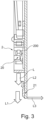
- eine schematische Schnittansicht der Frontplatte, der Beleuchtungsvorrichtung und des optischen Element nach Figur 2;
- Figur 3a:
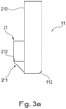
- eine Detailansicht der unteren Kante der Frontplatte mit optischem Element aus Figur 3;
- Figur 3b:
- eine weitere Detailansicht der unteren Kante der Frontplatte mit optischem Element aus Figur 3;
- Figur 4:
- eine schematische Blockdarstellung der Ausführungsform der erfindungsgemäßen Dunstabzugshaube nach Figur 1 mit der Frontplatte in einer ersten Position;
- Figur 5:
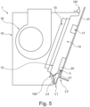
- eine schematische Blockdarstellung einer der Ausführungsform der erfindungsgemäßen Dunstabzugshaube nach Figur 4 mit der Frontplatte in einer zweiten Position;
- Figur 6:
- eine schematische, perspektivische Schnittansicht des Bereiches der Unterkante einer Ausführungsform der Frontplatte; und
- Figur 7:
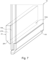
- eine schematische, perspektivische Schnittansicht des Bereiches der Unterkante einer weiteren Ausführungsform der Frontplatte.
-
In Figur 1 ist eine Ausführungsform einer erfindungsgemäßen Dunstabzugshaube 1 gezeigt. Die Dunstabzugshaube 1 weist in der dargestellten Ausführungsform ein Dunstabzugsgehäuse 10 und eine Frontklappe 11 auf. In dem Dunstabzugsgehäuse 10 ist das Gebläse 16 der Dunstabzugshaube 1 aufgenommen. Die Vorderseite des Dunstabzugsgehäuses 10 ist von der Horizontalen nach oben geneigt. In der Vorderseite ist eine Einlassöffnung 12 eingebracht, in der ein Filterelement 15 eingesetzt ist. Die Größe der Einlassöffnung 12 ist geringer als die Größe der Vorderseite des Dunstabzugsgehäuses 10. Die Einlassöffnung 12 wird in der gezeigten Ausführungsform daher durch den Boden einer Vertiefung in der Vorderseite des Dunstabzugsgehäuses 10 gebildet. Dadurch wird in der Vorderseite des Dunstabzugsgehäuses 10 ein Absaugraum 14 gebildet. Nach vorne ist der Absaugraum 14 teilweise durch die Frontklappe 11 begrenzt. Die Frontklappe 11 ist in der in Figur 1 gezeigten Ausführungsform parallel zu der Vorderseite des Dunstabzugsgehäuses 10 und zudem parallel zu der Einsaugöffnung 12 angeordnet. Die Unterkante der Frontklappe 11 ist in dem in Figur 1 gezeigten Zustand zu der Unterseite des Dunstabzugsgehäuses 10 und insbesondere zu der Unterseite des Absaugraums 14 nach oben versetzt. Aus diesem Zustand kann die Frontplatte 11 aber auch in einen Zustand gebracht werden, in dem die Frontplatte 11 so nach unten verschoben ist, dass die Unterkante der Frontplatte 11 in der Ebene der Unterseite des Dunstabzugsgehäuses liegt, was später unter Bezugnahme auf die Figuren 4 und 5 genauer erläutert wird.
-
Durch den Versatz der Unterkante der Frontplatte 11 nach oben ist ein Einsaugspalt 13 gebildet, über den Dünste und Wrasen in den Absaugraum 14 und insbesondere zu der Einlassöffnung 12 gelangen können. Auch an den seitlichen Rändern der Frontplatte 11 kann zwischen der Vorderseite des Dunstabzugsgehäuses 10 und der Innenseite der Frontplatte 11 ein Spalt zum Einlass von Dünsten und Wrasen gebildet sein. Zu diesem Zweck kann die Frontplatte 11 in einem Abstand zu der Vorderseite des Dunstabzugsgehäuses 10 angeordnet sein. Die Breite der Frontplatte 11 entspricht dabei vorzugsweise der Breite des Dunstabzugsgehäuses 10 und kann auch größer als die Breite des Dunstabzugsgehäuses 10 sein.
-
In der Ausführungsform nach Figur 1 ist an der Innenseite der Frontklappe 11 eine Beleuchtungsvorrichtung 2 angeordnet.
-
Die Beleuchtungsvorrichtung 2 ist insbesondere aus Figur 2 zu erkennen. Die Beleuchtungsvorrichtung 2 erstreckt sich in Breitenrichtung der Frontplatte 11, weist aber in der dargestellten Ausführungsform eine geringere Breite als die Frontplatte 11 auf. Insbesondere ist in der dargestellten Ausführungsform die Beleuchtungsvorrichtung 2 zwischen zwei Schienen einer Halterung 18 angeordnet, die in Höhenrichtung der Frontplatte 11 jeweils in einem Abstand zu den Seitenrändern der Frontplatte 11 angeordnet sind. An dem oberen Ende der Halterung sind im Bereich der Oberkante der Frontplatte 11 Scharniere 181 vorgesehen, über die die Frontplatte mit dem Dunstabzugsgehäuse 10 verbunden werden kann.
-
Die Beleuchtungsvorrichtung 2 ist über einen Verbindungskanal 170 mit einem Elektronikkasten 17 verbunden, der zu der Beleuchtungsvorrichtung 2 nach oben versetzt an der Innenseite der Frontplatte 11 angeordnet ist.
-
Die Beleuchtungsvorrichtung 2 weist eine Abdeckung 200 auf, die in Figur 2 transparent gezeigt ist, um den Einblick in das Innere der Abdeckung 200 zu ermöglichen. Unter der Abdeckung 200 sind Lichtquellen 20 der Beleuchtungsvorrichtung 2 angeordnet. In der gezeigten Ausführungsform sind sechs Lichtquellen 20 nebeneinander angeordnet. Die Erfindung ist aber nicht auf diese Anzahl beschränkt. Die Abdeckung 200 kann auch Gehäuse sein, das die Lichtquellen 20 und gegebenenfalls weitere Teile (nicht gezeigt) der Beleuchtungsvorrichtung 2 vollständig umgibt. In der Unterseite der Abdeckung 200 sind Lichtauslässe 2001 vorgesehen, über die Licht von den Lichtquellen 20 nach unten aus der Abdeckung 200 und damit der Beleuchtungsvorrichtung 2 austreten kann. An der unteren Kante der Frontplatte 11 ist an der Innenseite der Frontplatte 11 ein optisches Element 21 befestigt. Das optische Element 21 erstreckt sich in der gezeigten Ausführungsform über die gesamte Breite der Frontplatte 11.
-
Wie sich aus Figur 3, Figur 3a und Figur 3b ergibt, besteht das optische Element 21 aus einem Grundkörper 210, der an dessen Unterseite eine Fase 211 aufweist, durch die eine Reflexionsfläche 212 gebildet wird, die zu der Innenseite der Frontplatte 11 geneigt ist. Insbesondere ist der kleinste Winkel zwischen der Reflexionsfläche 212 und der Innenseite der Frontplatte 11 beispielsweise 45°.
-
Die Bauhöhe des optischen Elementes 21 ist bei der gezeigten Ausführungsform geringer als Bauhöhe der Beleuchtungsvorrichtung 2 aber insbesondere größer als der Abstand zwischen der Innenseite der Frontplatte 11 und dem Lichtauslass 2001. Hierdurch wird das von der Beleuchtungsvorrichtung 2 ausgegebene Licht L, das nach unten gerichtet ist, aufgeteilt in Licht L1, das an dem optischen Element 21 vorbeistrahlt, und Licht L2, das in das optische Element 21 eintritt. Wie sich aus Figur 3b ergibt, wird dieses Licht L2 an der Reflexionsfläche 212 in dem optischen Element 21 umgelenkt und tritt durch den unteren Bereich der Frontplatte 11 hindurch und kann an der Vorderseite bzw. Außenseite der Frontplatte 11 austreten. Hierdurch wird die Frontplatte 11 im unteren Bereich, gegebenenfalls auch teilweise über die Unterkante 110 ausgeleuchtet. Das von dem optischen Element nach vorne ausgegebene Licht ist in den Figuren mit L3 bezeichnet.
-
In Figur 4 ist eine Ausführungsform der Dunstabzugshaube 1 nach Figur 1 in Blockdarstellung gezeigt. In dem in Figur 4 gezeigten Zustand ist die Frontplatte 11 so zu dem Dunstabzugsgehäuse 10 positioniert, dass die Unterkante der Frontplatte 11 mit der Unterseite des Dunstabzugsgehäuses 10 auf einer Ebene liegt. Zwischen der Innenseite der Frontplatte 11 und der Vorderseite des Dunstabzugsgehäuses 10 liegt zumindest ein an der Unterseite nach vorne ein Abstand, durch den Dünste und Wrasen in den Absaugraum 14 eingesaugt werden kann. Wie sich aus Figur 4 ergibt, wird das Licht L, das von der Beleuchtungsvorrichtung 2 und insbesondere von der der Lichtquelle 20 der Beleuchtungsvorrichtung 2 ausgegeben wird, im Wesentlichen parallel zu der Innenseite der Frontplatte 11 nach unten ausgegeben. Durch das optisches Element 21, das an der unteren Kante der Innenseite der Frontplatte 11 angeordnet ist, wird das Licht L teilweise abgelenkt. Hierdurch werden zwei Lichtstrahlen L2 und L3 gebildet. Das Licht L1 wird im Wesentlichen in der ursprünglichen Richtung des Lichts L, das heißt parallel zu der Innenseite der Frontplatte 11 ausgegeben und tritt über den Einsaugspalt 13 nach unten aus. Das Licht L3 hingegen wird durch den Teil des Lichts L erzeugt, der in das optische Element 21 eintritt und in diesem umgelenkt wird, gebildet. Dieses Licht tritt über die Vorderseite bzw. Außenseite der Frontplatte 11 im Wesentlichen senkrecht zu der ursprünglichen Richtung des Lichts L aus. Somit werden durch das Licht L1 die die Dunstabzugshaube 1 anströmenden Dünste und Wrasen angeleuchtet. Durch das Licht L3 hingegen wird der untere Bereich der Frontplatte 11 ausgeleuchtet.
-
In Figur 5 ist die Dunstabzugshaube 1 in einem Zustand gezeigt, in dem die Frontplatte 11 gegenüber dem Dunstabzugsgehäuse 10 nach oben verschoben ist. In diesem Zustand liegt die Unterkante der Frontplatte 11 zu der Unterkante des Dunstabzugsgehäuses 10 nach oben versetzt. Hierdurch wird der Einsaugspalt 13 vergrößert. Dieser Zustand der Dunstabzugshaube 1 kann auch als Betriebszustand bezeichnet werden. In diesem Zustand wird, wie bezüglich Figur 4 bereits beschrieben, das Licht L von der Beleuchtungsvorrichtung 2 und insbesondere von der Lichtquelle 20 in einen Lichtstrahl L1 und einen Lichtstrahl L2 aufgeteilt. Die Unterkante der Frontplatte 11 liegt in einer Ebene, die über der Unterseite des Dunstabzugsgehäuses 10 liegt. Allerdings liegt die Unterkante der Frontplatte 11 auch in dem Betriebszustand unter der Ebene der Unterkante der Einlassöffnung 12 des Dunstabzugsgehäuses 10. Somit ist für den Benutzer im Betriebszustand die untere Schräge 140 des Absaugraumes 14 von vorne sichtbar.
-
Wie in Figur 5 schematisch angedeutet, wird durch das Licht L die untere Schräge 140 des Absaugraumes 14 angeleuchtet. Da das Licht L von der Beleuchtungsvorrichtung 2 in der Regel in Form eines Lichtkegels ausgegeben wird, wird zumindest ein Teil des Lichts L auf die untere Schräge 140 gerichtet. Dies ist in Figur 5 durch den Pfeil L4 schematisch angedeutet. Somit wird in dem Betriebszustand der Dunstabzugshaube 1 durch das Licht L1 zumindest ein Teil der die Dunstabzugshaube 1 anströmenden Dünste und Wrasen, durch das Licht L4 zumindest ein Teil der unteren Schräge 140 des Absaugraumes und durch das Licht L3 der untere Bereich der Frontplatte 11 beleuchtet beziehungsweise angeleuchtet.
-
Die Frontplatte 11 kann von dem in Figur 4 gezeigten, geschlossenen Zustand oder Ruhezustand in den in der Figur 5 gezeigten Betriebszustand beispielsweise durch den Betätigungsmechanismus 182, der in Figuren 1 und 2 schematisch gezeigt ist, gebracht werden. Der Betätigungsmechanismus 182 kann zusätzlich auch für ein Verschwenken der Frontplatte 11 verwendet werden, um dem Benutzer einen Zugriff auf die in der Einlassöffnung 12 und das darin vorgesehene Filterelement 15 oder zu anderen Instandhaltungs- und Reinigungszwecken zu ermöglichen.
-
In Figur 6 ist eine Ausführungsform der Frontplatte 11 im unteren Bereich gezeigt. Bei dieser Ausführungsform ist das optische Element 21 an der unteren Kante der Innenseite der Frontplatte 11 angeordnet. Zudem ist in der gezeigten Ausführungsform eine Beschichtung oder Druckschicht 213 an der Innenseite der Frontplatte 11 vorgesehen. In dem Bereich der Fase 211 des optischen Elementes 21 ist die Beschichtung oder Bedruckung ausgespart, so dass ein lichtdurchlässiger Bereich 113 gebildet wird. Hierdurch kann das Einkoppeln des in dem optischen Element 21 umgelenkten Lichts L2 gezielt auf den unteren Bereich der Frontplatte 11 gerichtet werden. Auch an der Innenseite des optischen Elementes 21 ist in Figur 6 schematisch eine weitere Beschichtung angedeutet, durch die die Lichtleitung in dem Grundkörper 210 zu der Fase 211 unterstützt werden kann. Schließlich ist in der gezeigten Ausführungsform an der Vorderseite der Frontplatte 11 eine untere Abschrägung 112 vorgesehen.
-
In Figur 7 ist eine weitere Ausführungsform des unteren Bereichs der Frontplatte 11 gezeigt. Die Ausführungsform nach Figur 7 unterscheidet sich von der in Figur 6 gezeigten Ausführungsform dadurch, dass bei der Ausführungsform nach Figur 7 das optische Element 21 zu der Unterkante der Frontplatte 11 nach oben versetzt angeordnet ist. Zudem ist bei dieser Ausführungsform an der Außenseite oder Vorderseite der unteren Kante der Frontplatte 11 eine Kantenabdeckung 111 angeordnet, die lichtundurchlässig ist. In der gezeigten Ausführungsform ist die Kantenabdeckung 111 An einem an der Unterkante der Frontplatte 11 vorgesehene Abstufung befestigt. Durch die in Figur 7 gezeigte Anordnung kann das von dem optischen Element 21 ausgegebene Licht L3 durch die Fläche der Frontplatte 11 nach vorne ausgegeben werden. Insbesondere wird das Licht in dem Bereich zwischen der Oberkante der lichtundurchlässigen Kantenabdeckung 111 und der Oberkante des lichtdurchlässigen Bereichs 113 der Bedruckung oder Beschichtung 114 der Innenseite der Frontplatte 11 nach vorne ausgegeben.
-
Die vorliegende Erfindung ist nicht auf die gezeigten Ausführungsformen beschränkt. Insbesondere kann die Form und Anbringung des optischen Elementes von dem gezeigten abweichen, solange dieses eine Reflexionsfläche aufweist, über die zumindest ein Teil des von der Beleuchtungsvorrichtung ausgegebenen Lichts in Richtung auf die Frontplatte umgelenkt werden kann. Auch die Ausgestaltung der Unterkante der Frontplatte kann von den gezeigten Ausführungsformen abweichen und beispielsweise nur eine Abrundung aufweisen.
-
Die erfindungsgemäße Beleuchtungsvorrichtung mit dem optischen Element kann auch als Linien- und Dunst-Beleuchtung bezeichnet werden.
-
Vorzugsweise dient die Erfindung dazu ein eine "atmosphärische" Beleuchtung, die auch als Stimmungslicht oder Moodlight bezeichnet werden kann, in einer Schrägesse zu schaffen.
-
Insbesondere kann vorzugsweise mit der vorliegenden Erfindung Licht verwendet werden, um Designelemente, wie beispielsweise Glaskanten oder unbedruckte Teile in der Frontplatte, insbesondere Glasplatte, zu betonen beziehungsweise hervorzuheben sowie den Absaugbereich der Dunstabzugshaube zu Beleuchten und die Dünste und Wrasen, die in die Dunstabzugshaube gesaugt werden, zu beleuchten.
-
Die Beleuchtungsvorrichtung, die erfindungsgemäß genutzt werden kann, kann eine Lichtquelle oder eine Gruppe von Lichtquellen aufweisen, die dann als eine betrachtet werden können. Zudem ist erfindungsgemäß ein optisches Element vorgesehen, um das Licht zu teilen und einen Teil des Lichts durch ein Designelement, insbesondere einen Bereich der Frontplatte zu führen. Die Lichtquelle(n) werden dabei in einem Abstand zu den Kanten der Frontplatte der Dunstabzugshaube angeordnet. Das optische Element kann als Lichtführung ausgestaltet sein und dazu verwendet werden, um den Lichtstrahl, der von der Beleuchtungsvorrichtung ausgegeben wird, aufzuteilen und einen Teil des Lichts durch die Frontplatte zu leiten.
-
Das optische Element kann an der Kante der Frontplatte oder zwischen der Kante und der Beleuchtungsvorrichtung positioniert werden. Der Abstand zwischen der Kante und der Beleuchtungsvorrichtung, die auch als Lichtquellenanordnung bezeichnet werden kann, kann variiert werden, ist aber größer als Null, um sicherzustellen, dass die Performance der Dunstabzugshaube nicht beeinflusst wird.
-
In einer Ausführungsform wird das Licht durch die Kante der Frontplatte geleitet. In einer weiteren Ausführungsform wird das Licht durch Bereiche der Frontplatte, die vorzugsweise aus Glas besteht und daher auch als Glasfrontplatte bezeichnet werden kann und die beispielsweise eine diffuse Bedruckung aufweist, geleitet. Es ist auch möglich das Licht vollständig durch einen vollständig bedruckungsfreien Bereich einer bedruckten Glasplatte / Frontplatte zu leiten.
-
Das optische Element kann aus einem transparenten oder transluzenten Material hergestellt sein und beispielsweise aus Kunststoff, wie Polykarbonat, bestehen.
-
Die Kanten und Oberflächen des optischen Elementes müssen, obwohl die Theorie etwas anderes suggerieren könnte, nicht vollständig optisch poliert sein, da es für die
-
Homogenität vorteilhaft sein kann eine geringe Rauigkeit zu haben. Alle von Benutzer berührbaren Kanten des optischen Elementes weisen vorzugsweise einen Radius oder Abschrägung von mindestens 0,25mm auf, um die Sicherheit des Benutzers zu gewährleisten.
-
Die vorliegende Erfindung weist eine Reihe von Vorteilen auf. Insbesondere ist die Beleuchtungsvorrichtung beziehungsweise Lichtquelle von der Kante der Frontplatte beabstandet angeordnet, so dass keine Behinderung des Luftstroms in die Dunstabzugshaube existiert und damit die Performance der Dunstabzugshaube nicht negativ beeinflusst wird. Vorzugsweise weist dazu zusätzlich das optische Element eine wesentlich geringe Bauhöhe auf, als die Beleuchtungsvorrichtung.
-
Zudem kann mit der vorliegenden Erfindung das Licht von einer oder einer Gruppe von Lichtquellen durch das optische Element aufgeteilt werden um separate Effekte zu erzielen. Insbesondere können zumindest zwei unterschiedliche Beleuchtungseffekte mit einer Art einer Beleuchtungsvorrichtung realisiert werden. Zudem erhält die Rückseite der Frontplatte ein sauberes Erscheinungsbild.
Bezugszeichenliste
-
- 1
- Dunstabzugshaube
- 10
- Dunstabzugsgehäuse / Backend
- 11
- Frontplatte
- 110
- Unterkante
- 111
- Kantenabdeckung
- 112
- Kantenabschrägung
- 113
- lichtdurchlässiger Bereich
- 114
- Bedruckung / Beschichtung
- 12
- Einlassöffnung
- 13
- Einsaugspalt
- 14
- Absaugraum
- 140
- untere Schräge
- 15
- Filterelement
- 16
- Gebläse
- 17
- Elektronikkasten
- 170
- Verbindungskanal
- 18
- Halterung
- 180
- Schienen
- 181
- Scharnier
- 182
- Betätigungsmechanismus
- 2
- Beleuchtungsvorrichtung
- 20
- Lichtquelle
- 200
- Abdeckung
- 2001
- Lichtauslass
- 21
- Optisches Element
- 210
- Grundkörper
- 211
- Fase
- 212
- Reflexionsfläche
- 213
- Bedruckung / Beschichtung Innenseite Frontplatte
- L
- Lichtausgabe Beleuchtungsvorrichtung
- L1
- Licht neben optischem Element
- L2
- Licht in optischem Element
- L3
- Licht von optischem Element nach vorne
- L4
- Licht von Lichtkegel