EP4517092A1 - Rotationsverdichter - Google Patents
Rotationsverdichter Download PDFInfo
- Publication number
- EP4517092A1 EP4517092A1 EP23819705.7A EP23819705A EP4517092A1 EP 4517092 A1 EP4517092 A1 EP 4517092A1 EP 23819705 A EP23819705 A EP 23819705A EP 4517092 A1 EP4517092 A1 EP 4517092A1
- Authority
- EP
- European Patent Office
- Prior art keywords
- cylinder
- blade
- refrigerant
- groove
- axial direction
- Prior art date
- Legal status (The legal status is an assumption and is not a legal conclusion. Google has not performed a legal analysis and makes no representation as to the accuracy of the status listed.)
- Pending
Links
Images

Classifications
-
- F—MECHANICAL ENGINEERING; LIGHTING; HEATING; WEAPONS; BLASTING
- F04—POSITIVE - DISPLACEMENT MACHINES FOR LIQUIDS; PUMPS FOR LIQUIDS OR ELASTIC FLUIDS
- F04C—ROTARY-PISTON, OR OSCILLATING-PISTON, POSITIVE-DISPLACEMENT MACHINES FOR LIQUIDS; ROTARY-PISTON, OR OSCILLATING-PISTON, POSITIVE-DISPLACEMENT PUMPS
- F04C18/00—Rotary-piston pumps specially adapted for elastic fluids
- F04C18/30—Rotary-piston pumps specially adapted for elastic fluids having the characteristics covered by two or more of groups F04C18/02, F04C18/08, F04C18/22, F04C18/24, F04C18/48, or having the characteristics covered by one of these groups together with some other type of movement between co-operating members
- F04C18/34—Rotary-piston pumps specially adapted for elastic fluids having the characteristics covered by two or more of groups F04C18/02, F04C18/08, F04C18/22, F04C18/24, F04C18/48, or having the characteristics covered by one of these groups together with some other type of movement between co-operating members having the movement defined in group F04C18/08 or F04C18/22 and relative reciprocation between the co-operating members
- F04C18/356—Rotary-piston pumps specially adapted for elastic fluids having the characteristics covered by two or more of groups F04C18/02, F04C18/08, F04C18/22, F04C18/24, F04C18/48, or having the characteristics covered by one of these groups together with some other type of movement between co-operating members having the movement defined in group F04C18/08 or F04C18/22 and relative reciprocation between the co-operating members with vanes reciprocating with respect to the outer member
- F04C18/3562—Rotary-piston pumps specially adapted for elastic fluids having the characteristics covered by two or more of groups F04C18/02, F04C18/08, F04C18/22, F04C18/24, F04C18/48, or having the characteristics covered by one of these groups together with some other type of movement between co-operating members having the movement defined in group F04C18/08 or F04C18/22 and relative reciprocation between the co-operating members with vanes reciprocating with respect to the outer member the inner and outer member being in contact along one line or continuous surfaces substantially parallel to the axis of rotation
-
- F—MECHANICAL ENGINEERING; LIGHTING; HEATING; WEAPONS; BLASTING
- F01—MACHINES OR ENGINES IN GENERAL; ENGINE PLANTS IN GENERAL; STEAM ENGINES
- F01C—ROTARY-PISTON OR OSCILLATING-PISTON MACHINES OR ENGINES
- F01C21/00—Component parts, details or accessories not provided for in groups F01C1/00 - F01C20/00
- F01C21/08—Rotary pistons
- F01C21/0809—Construction of vanes or vane holders
- F01C21/0818—Vane tracking; control therefor
- F01C21/0827—Vane tracking; control therefor by mechanical means
- F01C21/0845—Vane tracking; control therefor by mechanical means comprising elastic means, e.g. springs
-
- F—MECHANICAL ENGINEERING; LIGHTING; HEATING; WEAPONS; BLASTING
- F04—POSITIVE - DISPLACEMENT MACHINES FOR LIQUIDS; PUMPS FOR LIQUIDS OR ELASTIC FLUIDS
- F04C—ROTARY-PISTON, OR OSCILLATING-PISTON, POSITIVE-DISPLACEMENT MACHINES FOR LIQUIDS; ROTARY-PISTON, OR OSCILLATING-PISTON, POSITIVE-DISPLACEMENT PUMPS
- F04C23/00—Combinations of two or more pumps, each being of rotary-piston or oscillating-piston type, specially adapted for elastic fluids; Pumping installations specially adapted for elastic fluids; Multi-stage pumps specially adapted for elastic fluids
- F04C23/008—Hermetic pumps
-
- F—MECHANICAL ENGINEERING; LIGHTING; HEATING; WEAPONS; BLASTING
- F04—POSITIVE - DISPLACEMENT MACHINES FOR LIQUIDS; PUMPS FOR LIQUIDS OR ELASTIC FLUIDS
- F04C—ROTARY-PISTON, OR OSCILLATING-PISTON, POSITIVE-DISPLACEMENT MACHINES FOR LIQUIDS; ROTARY-PISTON, OR OSCILLATING-PISTON, POSITIVE-DISPLACEMENT PUMPS
- F04C2250/00—Geometry
Definitions
- the present disclosure relates to a rotary compressor.
- a rotary compressor is known as one of compressors used for a refrigerating apparatus, an air conditioning device, or the like (refer to PTL 1).
- the core diameter is reduced, and thus a refrigerant displacement amount of a compression portion may be reduced.
- a low-pressure refrigerant for example, a refrigerant in which a combustion class is set to have mild-flammability (A2L) or high-flammability (A3)
- the displacement amount is required to be about twice as much as that in a case of R32. Accordingly, it is desired to miniaturize the rotary compressor while securing the displacement amount.
- the present disclosure has been made in view of such circumstances, and an object of the present disclosure is to provide a rotary compressor that can be miniaturized while securing a refrigerant displacement amount from a compression portion.
- a rotary compressor includes a cylinder (60) in which a compression chamber (60A) with a cylindrical shape inside is formed, a piston rotor (63) that compresses a refrigerant by eccentrically rotating inside the compression chamber, a blade (64) that partitions a space of the compression chamber by abutting on an outer peripheral surface of the piston rotor, and a pressing spring that presses a base end portion of the blade in a direction in which a tip portion of the blade abuts on the outer peripheral surface of the piston rotor, in which the cylinder includes a blade groove (66) for slidably holding the base end portion (64b) of the blade, a bridge portion (70) that is provided on a rear end side of the blade groove and forms an outer peripheral portion of the cylinder, and a spring groove (72) that is formed in the bridge portion and accommodates the pressing spring, the spring groove is formed to face in a horizontal direction orthogonal to an axial direction of the cylinder at a center position
- a rotary compressor can be miniaturized while securing a refrigerant displacement amount from a compression portion.
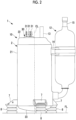
- a rotary compressor (hereinafter, simply referred to as a "compressor") 1 according to the present embodiment is a sealed-type electric rotary compressor used for, for example, an air conditioner, a refrigerating apparatus, or the like.
- the compressor 1 includes a compressor main body 10 and an accumulator 12.
- the accumulator 12 is connected to the compressor main body 10 via a suction pipe 11.
- the compressor main body 10 includes an approximately cylindrical housing 2, a rotary shaft body 3, an electric motor 5, and a rotary compression portion 6.
- a rotational axis CL of the rotary shaft body 3 coincides with a central axis of the housing 2.
- the rotary shaft body 3 is disposed such that an extending direction thereof is an up-down direction, and rotates around the rotational axis CL in the housing 2.
- the housing 2 is a sealed-type and extends in the up-down direction.
- the housing 2 includes a main body portion 21 having a cylindrical shape, and an upper cover portion 22 and a lower cover portion 23 that close upper and lower openings of the main body portion 21.
- An oil reservoir for storing a lubricant is formed in a bottom portion of the housing 2.
- a liquid surface of the oil reservoir at a time of initial enclosure of oil is located above the rotary compression portion 6.
- the rotary compression portion 6 is driven in the oil reservoir.
- a discharge pipe 13 and a terminal block 30 are provided in the upper cover portion 22.
- the discharge pipe 13 penetrates the upper cover portion 22 in a thickness direction, has a lower portion disposed in the housing 2, and has an upper portion disposed outside the housing 2.
- the discharge pipe 13 discharges the compressed refrigerant to the outside of the housing 2.
- the terminal block 30 is provided with three power supply terminals 31 that supply power to the electric motor 5.
- the power supply terminals 31 are supplied with three-phase power from an inverter device (not shown).
- a low-pressure refrigerant is used, and for example, a refrigerant with mild-flammability (A2L) or a refrigerant with high-flammability (A3) such as propane is used.
- A2L refrigerant with mild-flammability
- A3 refrigerant with high-flammability
- R410A, R32, R1234yf, and a natural refrigerant R290, Iso-butane, or the like
- the electric motor 5 is accommodated in a central portion of the housing 2 in the up-down direction.
- the electric motor 5 includes a rotor 51 and a stator 52.
- the rotor 51 is fixed to an outer peripheral surface of the rotary shaft body 3 and is disposed above the rotary compression portion 6.
- the stator 52 is disposed to surround an outer peripheral surface of the rotor 51 and is fixed to an inner surface 21a of the main body portion 21 of the housing 2.
- Power is supplied to the stator 52 from each of the power supply terminals 31 via wiring 32.
- the electric motor 5 rotates the rotary shaft body 3 by the power supplied from the power supply terminals 31.
- the rotary compression portion 6 is disposed in a state of being sandwiched from above and below by an upper bearing 4A and a lower bearing 4B.
- Each of the upper bearing 4A and the lower bearing 4B is formed of a metallic material and is fixed to the cylinder 60 configuring the rotary compression portion 6 by bolts 61.
- the rotary shaft body 3 is rotatably supported around the rotational axis CL by the upper bearing 4A and the lower bearing 4B.
- the rotary compression portion 6 is disposed at the bottom portion in the housing 2 below the electric motor 5.
- the rotary compression portion 6 includes the cylinder 60, an eccentric shaft portion 62, and a piston rotor 63.
- the cylinder 60 is formed with a compression chamber 60A, a suction hole 60B, and a discharge hole (not shown).
- the compression chamber 60A is formed inside the cylinder 60.
- the piston rotor 63 is accommodated in the compression chamber 60A.
- the rotary compression portion 6 is fixed to the inner surface 21a of the main body portion 21 of the housing 2.
- the upper bearing 4A sandwiching the cylinder 60 is fixed to the inner surface 21a of the main body portion 21 of the housing 2.
- the upper bearing 4A is fixed by performing plug welding at a plurality of locations in a circumferential direction of the housing 2.
- plug welding shrink fitting, cold fitting, or the like may be used.
- the eccentric shaft portions 62 are provided at a lower end portion of the rotary shaft body 3 and are provided inside the piston rotor 63 in a state of being offset from the central axis of the rotary shaft body 3 in a direction orthogonal to the central axis.
- the piston rotor 63 has a cylindrical shape with an outer diameter smaller than an inner diameter of the cylinder 60, is disposed inside the cylinder 60, and is fixed in a state of being mounted to an outer periphery of the eccentric shaft portion 62.
- the piston rotor 63 rotates eccentrically with respect to the rotational axis CL as the rotary shaft body 3 rotates.
- the suction hole 60B is a hole for guiding the refrigerant into the inside of the cylinder 60, and is formed in a direction orthogonal to the rotational axis CL.
- a high-pressure refrigerant discharged from the discharge hole (not shown) formed in the cylinder 60 is guided into a space formed between a discharge cover 65 and the upper bearing 4A, and then is guided into an internal space of the housing 2.
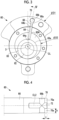
- Fig. 3 is a plan view of the cylinder 60.
- the cylinder 60 is provided with a blade 64 that divides the compression chamber 60A into two.
- a blade groove 66 formed to extend in a radial direction is formed in the cylinder 60.
- the blade 64 is slidably guided on an inner surface 66a of the blade groove 66 and is forward/backward movably held with respect to the piston rotor 63 in a direction of approaching and separating from the piston rotor 63.
- a base end portion 64b of the blade 64 on an outside in the radial direction is elastically pressed by a pressing spring (compression spring) (not shown), and a tip portion 64a is always in a state of being pressed against an outer peripheral surface 63a of the piston rotor 63.
- the eccentric shaft portion 62 has an outer diameter slightly smaller than the inner diameter of the piston rotor 63. Accordingly, in a case where the rotary shaft body 3 rotates, the eccentric shaft portion 62 revolves around the rotary shaft body 3, and the piston rotor 63 eccentrically rotates in the cylinder 60. In this case, since the blade 64 is pressed by the pressing spring (not shown), the tip portion 64a moves forward and backward following a movement of the piston rotor 63 and is always pressed against the piston rotor 63.
- An outer diameter D1 of the cylinder 60 is 90 mm or more and 105 mm or less.
- An inner diameter D2 of the compression chamber 60A is 37 mm or more and 50 mm or less.
- a through-hole 66b that penetrates the blade groove 66 in the axial direction (that is, the rotational axis CL direction) of the cylinder 60 at a rear end, that is, an outer peripheral side is formed.
- the through-hole 66b has a cylindrical shape.
- a bridge portion 70 is provided on a further rear end side, that is, an outer peripheral side of the through-hole 66b.
- the bridge portion 70 forms an outer peripheral portion of the cylinder 60. As can be seen from Fig. 3 , the bridge portion 70 is weak in terms of strength at a position in which a wall thickness is a thinnest in the cylinder 60. In addition, since the bridge portion 70 is formed with a spring groove 72 (refer to Fig. 4 ) that accommodates the pressing spring, the strength is further weakened.
- Fig. 4 is a view showing a cross section in arrow IV of Fig. 3 and in which the cylinder 60 is viewed in a longitudinal cross section, in a cross section including a central axis of the spring groove 72, the blade groove 66, and the bridge portion 70.
- the spring groove 72 is formed to face in a horizontal direction orthogonal to the axial direction (that is, the rotational axis CL direction) of the cylinder 60 at a center position in the axial direction. That is, a spring groove central axis CL2 is provided to face horizontally. It is preferable that the spring groove central axis CL2 is provided to intersect with the rotational axis CL.
- a diameter of the spring groove 72 is set to, for example, ⁇ 6 or more and ⁇ 10 or less.
- a remaining portion 70a of the bridge portion 70 is provided on each of both sides of the spring groove 72 in the axial direction. In these remaining portions 70a, the strength of the bridge portion 70 is secured.
- a horizontal direction dimension of the remaining portion 70a is set as v and an axial direction dimension thereof is set as h, v ⁇ h is satisfied. That is, the axial direction dimension h is larger than the horizontal direction dimension v of the remaining portion 70a, and the remaining portion 70a has a longitudinally long rectangular shape as viewed in Fig. 4 .
- a value of h/v is more preferably in the following range. 1.4 ⁇ h/v ⁇ 3 .5 .
- the horizontal direction dimension v is, for example, 2.0 mm or more and 7.5 mm or less.
- the axial direction dimension h is, for example, 2.5 mm or more and 8.5 mm or less.
- the above-described compressor 1 operates as follows.
- the refrigerant guided from the evaporator (not shown) is taken into the accumulator 12 via the inlet pipe 15.
- the refrigerant is gas-liquid-separated in the accumulator 12, and the gas phase thereof is guided to the rotary compression portion 6 via the suction pipe 11.
- the refrigerant is guided to the compression chamber 60A via the suction hole 60B.
- a volume of the compression chamber 60A gradually decreases, and the refrigerant is compressed.
- the refrigerant after being compressed is guided to the internal space of the housing 2 after passing through the space in the discharge cover 65 via the discharge hole.
- the refrigerant discharged into the internal space of the housing 2 is guided to a condenser (not shown) from the discharge pipe 13 provided in an upper portion of the housing 2.
- the bridge portion 70 that is provided on a rear end side of the blade groove 66 and forms the outer peripheral portion of the cylinder 60 is weak in terms of strength at a position in which the wall thickness is the thinnest in the cylinder 60.
- the bridge portion 70 is formed with the spring groove 72 that accommodates the pressing spring, the strength is further weakened.
- the present inventors or the like have found a shape of the bridge portion 70 that secures the strength of the bridge portion 70 under such a restriction. That is, in a case where the cylinder 60 is viewed in a longitudinal cross section, in a cross section including the spring groove central axis CL2 of the spring groove 72, the blade groove 66, and the bridge portion 70 (refer to Fig. 4 ), in a case where a dimension of the remaining portion 70a of the bridge portion 70 in the horizontal direction, which is located on each of both sides of the spring groove 72 in the axial direction, is set as v, and a dimension in the axial direction is set as h, v ⁇ h is satisfied. h is set to be larger than v, that is, the axial direction dimension h is set to be larger than the horizontal direction dimension v of the remaining portion 70a.
- a desired strength of the bridge portion 70 can be obtained by increasing the horizontal direction dimension v to secure an area of the remaining portion 70a.
- the outer diameter D1 of the cylinder 60 is reduced, and the horizontal direction dimension v cannot be increased to obtain the refrigerant displacement amount. Therefore, in the present embodiment, the axial direction dimension h is set to be larger than the horizontal direction dimension v to secure the area of the remaining portion 70a and to obtain the desired strength of the bridge portion 70.
- the desired refrigerant displacement amount can be obtained, and thus a compressor having a predetermined performance can be provided.
- a rotary compressor (1) includes a cylinder (60) in which a compression chamber (60A) with a cylindrical shape inside is formed, a piston rotor (63) that compresses a refrigerant by eccentrically rotating inside the compression chamber, a blade (64) that partitions a space of the compression chamber by abutting on an outer peripheral surface of the piston rotor, and a pressing spring that presses a base end portion of the blade in a direction in which a tip portion of the blade abuts on the outer peripheral surface of the piston rotor, in which the cylinder includes a blade groove (66) for slidably holding the base end portion (64b) of the blade, a bridge portion (70) that is provided on a rear end side of the blade groove and forms an outer peripheral portion of the cylinder, and a spring groove (72) that is formed in the bridge portion and accommodates the pressing spring, the spring groove is formed to face in a horizontal direction orthogonal to an axial direction of the cylinder at
- a refrigerant with mild-flammability or a refrigerant with high-flammability is used as the refrigerant.
Landscapes
- Engineering & Computer Science (AREA)
- Mechanical Engineering (AREA)
- General Engineering & Computer Science (AREA)
- Applications Or Details Of Rotary Compressors (AREA)
Applications Claiming Priority (2)
| Application Number | Priority Date | Filing Date | Title |
|---|---|---|---|
| JP2022093808A JP2023180461A (ja) | 2022-06-09 | 2022-06-09 | ロータリ圧縮機 |
| PCT/JP2023/019929 WO2023238725A1 (ja) | 2022-06-09 | 2023-05-29 | ロータリ圧縮機 |
Publications (2)
| Publication Number | Publication Date |
|---|---|
| EP4517092A1 true EP4517092A1 (de) | 2025-03-05 |
| EP4517092A4 EP4517092A4 (de) | 2025-08-13 |
Family
ID=89118247
Family Applications (1)
| Application Number | Title | Priority Date | Filing Date |
|---|---|---|---|
| EP23819705.7A Pending EP4517092A4 (de) | 2022-06-09 | 2023-05-29 | Rotationsverdichter |
Country Status (5)
| Country | Link |
|---|---|
| EP (1) | EP4517092A4 (de) |
| JP (1) | JP2023180461A (de) |
| CN (1) | CN119343528A (de) |
| AU (1) | AU2023285487A1 (de) |
| WO (1) | WO2023238725A1 (de) |
Family Cites Families (7)
| Publication number | Priority date | Publication date | Assignee | Title |
|---|---|---|---|---|
| JPH01247786A (ja) * | 1988-03-29 | 1989-10-03 | Toshiba Corp | 2シリンダ型ロータリ式圧縮機 |
| JP2000283073A (ja) * | 1999-03-26 | 2000-10-10 | Sanyo Electric Co Ltd | ロータリ圧縮機 |
| JP5079670B2 (ja) * | 2008-11-20 | 2012-11-21 | 日立アプライアンス株式会社 | ロータリ圧縮機 |
| WO2015062048A1 (zh) * | 2013-10-31 | 2015-05-07 | 广东美芝制冷设备有限公司 | 旋转式压缩机及制冷循环装置 |
| JP6394681B2 (ja) | 2016-11-09 | 2018-09-26 | 株式会社富士通ゼネラル | ロータリ圧縮機 |
| CN106870373B (zh) * | 2017-03-27 | 2019-09-06 | 广东美芝制冷设备有限公司 | 旋转压缩机及具有其的制冷循环装置 |
| CN111502991B (zh) * | 2020-04-29 | 2022-05-31 | 广东美芝制冷设备有限公司 | 旋转压缩机及其滑片组件和制冷循环系统 |
-
2022
- 2022-06-09 JP JP2022093808A patent/JP2023180461A/ja active Pending
-
2023
- 2023-05-29 CN CN202380044479.6A patent/CN119343528A/zh active Pending
- 2023-05-29 AU AU2023285487A patent/AU2023285487A1/en active Pending
- 2023-05-29 EP EP23819705.7A patent/EP4517092A4/de active Pending
- 2023-05-29 WO PCT/JP2023/019929 patent/WO2023238725A1/ja not_active Ceased
Also Published As
| Publication number | Publication date |
|---|---|
| EP4517092A4 (de) | 2025-08-13 |
| CN119343528A (zh) | 2025-01-21 |
| JP2023180461A (ja) | 2023-12-21 |
| WO2023238725A1 (ja) | 2023-12-14 |
| AU2023285487A1 (en) | 2024-12-19 |
Similar Documents
| Publication | Publication Date | Title |
|---|---|---|
| US20220268277A1 (en) | Multi-bearing scroll compressor to enhance load management | |
| US6428296B1 (en) | Horizontal scroll compressor having an oil injection fitting | |
| AU2016225716A1 (en) | Scroll-type compressor | |
| JP7280726B2 (ja) | スクロール圧縮機 | |
| EP3940230B1 (de) | Verdichter | |
| US8360752B2 (en) | Electric compressor | |
| US12421967B2 (en) | Rotary compressor and refrigeration device | |
| EP4513038A1 (de) | Rotationsverdichter und verfahren zur herstellung eines rotationsverdichters | |
| EP1555437A1 (de) | Verdichter | |
| KR20200140967A (ko) | 전동식 압축기 | |
| EP2236829B1 (de) | Versiegelungs-spiralverdichter | |
| EP4517092A1 (de) | Rotationsverdichter | |
| EP3922854B1 (de) | Rotationsverdichter, verfahren zur herstellung eines rotationsverdichters und kältekreislaufvorrichtung | |
| US10533554B2 (en) | Cylinder-rotation compressor with improved vane and suction passage locations | |
| US10125770B2 (en) | Cylinder-rotation compressor with a discharge valve | |
| US12129852B2 (en) | Compressor | |
| EP4621241A1 (de) | Verdichter | |
| US10253773B2 (en) | Attachment structure for compressor | |
| JP2019190468A (ja) | スクロール圧縮機 | |
| EP4621242A1 (de) | Verdichter | |
| EP4417814A1 (de) | Verdichter und entwurfsverfahren dafür | |
| EP4242460A1 (de) | Spiralverdichter | |
| EP3409944A1 (de) | Hermetischer verdichter und verfahren zur herstellung eines hermetischen verdichters |
Legal Events
| Date | Code | Title | Description |
|---|---|---|---|
| STAA | Information on the status of an ep patent application or granted ep patent |
Free format text: STATUS: THE INTERNATIONAL PUBLICATION HAS BEEN MADE |
|
| PUAI | Public reference made under article 153(3) epc to a published international application that has entered the european phase |
Free format text: ORIGINAL CODE: 0009012 |
|
| STAA | Information on the status of an ep patent application or granted ep patent |
Free format text: STATUS: REQUEST FOR EXAMINATION WAS MADE |
|
| 17P | Request for examination filed |
Effective date: 20241129 |
|
| AK | Designated contracting states |
Kind code of ref document: A1 Designated state(s): AL AT BE BG CH CY CZ DE DK EE ES FI FR GB GR HR HU IE IS IT LI LT LU LV MC ME MK MT NL NO PL PT RO RS SE SI SK SM TR |
|
| A4 | Supplementary search report drawn up and despatched |
Effective date: 20250710 |
|
| RIC1 | Information provided on ipc code assigned before grant |
Ipc: F04C 18/356 20060101AFI20250704BHEP Ipc: F04C 29/00 20060101ALI20250704BHEP Ipc: F01C 21/08 20060101ALI20250704BHEP Ipc: F04C 23/00 20060101ALI20250704BHEP |
|
| DAV | Request for validation of the european patent (deleted) | ||
| DAX | Request for extension of the european patent (deleted) |