EP4516729A1 - Hydrogen production device, power generation system, and steelmaking system - Google Patents
Hydrogen production device, power generation system, and steelmaking system Download PDFInfo
- Publication number
- EP4516729A1 EP4516729A1 EP23795852.5A EP23795852A EP4516729A1 EP 4516729 A1 EP4516729 A1 EP 4516729A1 EP 23795852 A EP23795852 A EP 23795852A EP 4516729 A1 EP4516729 A1 EP 4516729A1
- Authority
- EP
- European Patent Office
- Prior art keywords
- catalyst
- accommodating tank
- diffuser tube
- raw material
- material gas
- Prior art date
- Legal status (The legal status is an assumption and is not a legal conclusion. Google has not performed a legal analysis and makes no representation as to the accuracy of the status listed.)
- Pending
Links
Images



Classifications
-
- C—CHEMISTRY; METALLURGY
- C01—INORGANIC CHEMISTRY
- C01B—NON-METALLIC ELEMENTS; COMPOUNDS THEREOF; METALLOIDS OR COMPOUNDS THEREOF NOT COVERED BY SUBCLASS C01C
- C01B3/00—Hydrogen; Gaseous mixtures containing hydrogen; Separation of hydrogen from mixtures containing it; Purification of hydrogen; Reversible storage of hydrogen
- C01B3/02—Production of hydrogen; Production of gaseous mixtures containing hydrogen
- C01B3/22—Production of hydrogen; Production of gaseous mixtures containing hydrogen by decomposition of gaseous or liquid organic compounds
- C01B3/24—Production of hydrogen; Production of gaseous mixtures containing hydrogen by decomposition of gaseous or liquid organic compounds of hydrocarbons
- C01B3/28—Production of hydrogen; Production of gaseous mixtures containing hydrogen by decomposition of gaseous or liquid organic compounds of hydrocarbons using moving solid particles, e.g. fluidised bed technique
-
- B—PERFORMING OPERATIONS; TRANSPORTING
- B01—PHYSICAL OR CHEMICAL PROCESSES OR APPARATUS IN GENERAL
- B01J—CHEMICAL OR PHYSICAL PROCESSES, e.g. CATALYSIS OR COLLOID CHEMISTRY; THEIR RELEVANT APPARATUS
- B01J21/00—Catalysts comprising the elements, oxides, or hydroxides of magnesium, boron, aluminium, carbon, silicon, titanium, zirconium, or hafnium
- B01J21/02—Boron or aluminium; Oxides or hydroxides thereof
-
- B—PERFORMING OPERATIONS; TRANSPORTING
- B01—PHYSICAL OR CHEMICAL PROCESSES OR APPARATUS IN GENERAL
- B01J—CHEMICAL OR PHYSICAL PROCESSES, e.g. CATALYSIS OR COLLOID CHEMISTRY; THEIR RELEVANT APPARATUS
- B01J23/00—Catalysts comprising metals or metal oxides or hydroxides, not provided for in group B01J21/00
- B01J23/70—Catalysts comprising metals or metal oxides or hydroxides, not provided for in group B01J21/00 of the iron group metals or copper
- B01J23/74—Iron group metals
-
- B—PERFORMING OPERATIONS; TRANSPORTING
- B01—PHYSICAL OR CHEMICAL PROCESSES OR APPARATUS IN GENERAL
- B01J—CHEMICAL OR PHYSICAL PROCESSES, e.g. CATALYSIS OR COLLOID CHEMISTRY; THEIR RELEVANT APPARATUS
- B01J8/00—Chemical or physical processes in general, conducted in the presence of fluids and solid particles; Apparatus for such processes
- B01J8/18—Chemical or physical processes in general, conducted in the presence of fluids and solid particles; Apparatus for such processes with fluidised particles
- B01J8/1818—Feeding of the fluidising gas
-
- C—CHEMISTRY; METALLURGY
- C01—INORGANIC CHEMISTRY
- C01B—NON-METALLIC ELEMENTS; COMPOUNDS THEREOF; METALLOIDS OR COMPOUNDS THEREOF NOT COVERED BY SUBCLASS C01C
- C01B2203/00—Integrated processes for the production of hydrogen or synthesis gas
- C01B2203/02—Processes for making hydrogen or synthesis gas
- C01B2203/0266—Processes for making hydrogen or synthesis gas containing a decomposition step
- C01B2203/0277—Processes for making hydrogen or synthesis gas containing a decomposition step containing a catalytic decomposition step
-
- C—CHEMISTRY; METALLURGY
- C01—INORGANIC CHEMISTRY
- C01B—NON-METALLIC ELEMENTS; COMPOUNDS THEREOF; METALLOIDS OR COMPOUNDS THEREOF NOT COVERED BY SUBCLASS C01C
- C01B2203/00—Integrated processes for the production of hydrogen or synthesis gas
- C01B2203/06—Integration with other chemical processes
-
- C—CHEMISTRY; METALLURGY
- C01—INORGANIC CHEMISTRY
- C01B—NON-METALLIC ELEMENTS; COMPOUNDS THEREOF; METALLOIDS OR COMPOUNDS THEREOF NOT COVERED BY SUBCLASS C01C
- C01B2203/00—Integrated processes for the production of hydrogen or synthesis gas
- C01B2203/08—Methods of heating or cooling
- C01B2203/0805—Methods of heating the process for making hydrogen or synthesis gas
- C01B2203/0833—Heating by indirect heat exchange with hot fluids, other than combustion gases, product gases or non-combustive exothermic reaction product gases
-
- C—CHEMISTRY; METALLURGY
- C01—INORGANIC CHEMISTRY
- C01B—NON-METALLIC ELEMENTS; COMPOUNDS THEREOF; METALLOIDS OR COMPOUNDS THEREOF NOT COVERED BY SUBCLASS C01C
- C01B2203/00—Integrated processes for the production of hydrogen or synthesis gas
- C01B2203/08—Methods of heating or cooling
- C01B2203/0805—Methods of heating the process for making hydrogen or synthesis gas
- C01B2203/085—Methods of heating the process for making hydrogen or synthesis gas by electric heating
-
- C—CHEMISTRY; METALLURGY
- C01—INORGANIC CHEMISTRY
- C01B—NON-METALLIC ELEMENTS; COMPOUNDS THEREOF; METALLOIDS OR COMPOUNDS THEREOF NOT COVERED BY SUBCLASS C01C
- C01B2203/00—Integrated processes for the production of hydrogen or synthesis gas
- C01B2203/10—Catalysts for performing the hydrogen forming reactions
- C01B2203/1041—Composition of the catalyst
- C01B2203/1047—Group VIII metal catalysts
- C01B2203/1052—Nickel or cobalt catalysts
- C01B2203/1058—Nickel catalysts
-
- C—CHEMISTRY; METALLURGY
- C01—INORGANIC CHEMISTRY
- C01B—NON-METALLIC ELEMENTS; COMPOUNDS THEREOF; METALLOIDS OR COMPOUNDS THEREOF NOT COVERED BY SUBCLASS C01C
- C01B2203/00—Integrated processes for the production of hydrogen or synthesis gas
- C01B2203/10—Catalysts for performing the hydrogen forming reactions
- C01B2203/1041—Composition of the catalyst
- C01B2203/1076—Copper or zinc-based catalysts
-
- C—CHEMISTRY; METALLURGY
- C01—INORGANIC CHEMISTRY
- C01B—NON-METALLIC ELEMENTS; COMPOUNDS THEREOF; METALLOIDS OR COMPOUNDS THEREOF NOT COVERED BY SUBCLASS C01C
- C01B2203/00—Integrated processes for the production of hydrogen or synthesis gas
- C01B2203/12—Feeding the process for making hydrogen or synthesis gas
- C01B2203/1205—Composition of the feed
- C01B2203/1211—Organic compounds or organic mixtures used in the process for making hydrogen or synthesis gas
- C01B2203/1235—Hydrocarbons
Definitions
- the present disclosure relates to a hydrogen production apparatus, a power generation system, and a steelmaking system.
- This application claims the benefit of priority to Japanese Patent Application No. 2022-073628 filed on April 27, 2022 , and contents thereof are incorporated herein.
- an apparatus including a reaction furnace, a raw material gas supply source, and a heating unit provided outside the reaction furnace (e.g., Patent Literature 1).
- the reaction furnace accommodates a catalyst.
- the raw material gas supply source supplies hydrocarbon to the reaction furnace.
- the heating unit is provided on the periphery of the reaction furnace and heats the inside of the reaction furnace.
- the pyrolysis reaction of hydrocarbon progresses efficiently at 800°C or more through use of a catalyst.
- the pyrolysis reaction of hydrocarbon is an endothermic reaction, and hence it is required to supply heat from outside.
- it is required to heat a furnace wall of the reaction furnace to at least an inside temperature(for example, 1,000°C or more) in order to heat the inside of the reaction furnace to 800°C or more.
- the reaction furnace needs to be formed of a material such as an expensive heat-resistant alloy having satisfactory heat conductivity while having a heat resistance of 1,000°C or more, causing a problem in that the cost for a heating apparatus and the reaction furnace is increased.
- the catalyst in the reaction furnace is heated from a wall surface, and hence a temperature difference occurs between the vicinity of the wall surface and the central portion when the volume of the catalyst becomes large.
- a temperature difference occurs between the vicinity of the wall surface and the central portion when the volume of the catalyst becomes large.
- the present disclosure has an object to provide a hydrogen production apparatus, a power generation system, and a steelmaking system that are capable of subjecting hydrocarbon to pyrolysis at low cost.
- a hydrogen production apparatus including: an accommodating tank; a heating unit placed in the accommodating tank; a first diffuser tube placed below the heating unit in the accommodating tank; a second diffuser tube placed below the first diffuser tube in the accommodating tank; a catalyst supply unit that supplies a catalyst containing any one or more of iron, nickel, copper, and aluminum from a supply port formed above the heating unit in the accommodating tank; a catalyst discharge unit that discharges the catalyst from a discharge port formed below the second diffuser tube in the accommodating tank; and a raw material gas supply unit that supplies a raw material gas containing at least hydrocarbon to the first diffuser tube and the second diffuser tube.
- a flow rate of the raw material gas to be supplied to the first diffuser tube by the raw material gas supply unit may be larger than a flow rate of the raw material gas to be supplied to the second diffuser tube.
- a superficial velocity ratio UO/Umf of a total of the raw material gas diffused from the first diffuser tube and the raw material gas diffused from the second diffuser tube may be 1.1 or more and 2.0 or less.
- a fluidized bed of the catalyst may be formed above the first diffuser tube, and a moving bed of the catalyst may be formed below the first diffuser tube.
- the accommodating tank may include: an upper portion having a tubular shape; and a lower portion, which is formed below the upper portion, and in which a horizontal cross-section area of an internal space is gradually decreased from above to below.
- the heating unit may be placed in the upper portion.
- the second diffuser tube may be placed in the lower portion.
- the accommodating tank may include one upper portion and a plurality of lower portions.
- a power generation system including: a hydrogen production apparatus including: an accommodating tank; a heating unit placed in the accommodating tank; a first diffuser tube placed below the heating unit in the accommodating tank; a second diffuser tube placed below the first diffuser tube in the accommodating tank; a catalyst supply unit that supplies a catalyst containing any one or more of iron, nickel, copper, and aluminum from a supply port formed above the heating unit in the accommodating tank; a catalyst discharge unit that discharges the catalyst from a discharge port formed below the second diffuser tube in the accommodating tank; and a raw material gas supply unit that supplies a raw material gas containing at least hydrocarbon to the first diffuser tube and the second diffuser tube; and a power generation apparatus that generates power through use of hydrogen produced by the hydrogen production apparatus.
- a hydrogen production apparatus including: an accommodating tank; a heating unit placed in the accommodating tank; a first diffuser tube placed below the heating unit in the accommodating tank; a second diffuser tube placed below the first diffuser tube in the accommodating tank; a catalyst supply unit that supplies a catalyst containing any
- a steelmaking system including: a hydrogen production apparatus including: an accommodating tank; a heating unit placed in the accommodating tank; a first diffuser tube placed below the heating unit in the accommodating tank; a second diffuser tube placed below the first diffuser tube in the accommodating tank; a catalyst supply unit that supplies a catalyst containing any one or more of iron, nickel, copper, and aluminum from a supply port formed above the heating unit in the accommodating tank; a catalyst discharge unit that discharges the catalyst from a discharge port formed below the second diffuser tube in the accommodating tank; and a raw material gas supply unit that supplies a raw material gas containing at least hydrocarbon to the first diffuser tube and the second diffuser tube; and a steelmaking apparatus that produces iron through use of hydrogen produced by the hydrogen production apparatus.
- a hydrogen production apparatus including: an accommodating tank; a heating unit placed in the accommodating tank; a first diffuser tube placed below the heating unit in the accommodating tank; a second diffuser tube placed below the first diffuser tube in the accommodating tank; a catalyst supply unit that supplies a catalyst containing any one
- FIG. 1 is a view for schematically illustrating a hydrogen production apparatus 100 according to this embodiment.
- the solid arrows indicate flows of a raw material gas and a generated gas.
- the dashed line arrows indicate flows of a catalyst and solid carbon.
- a heating unit 120 is indicated by hatching.
- the hydrogen production apparatus 100 includes an accommodating tank 110, the heating unit 120, a first diffuser tube 130, a second diffuser tube 140, a catalyst supply unit 150, a catalyst discharge unit 160, and a raw material gas supply unit 170.
- the upper portion 112 is a portion having a tubular shape, such as a cylinder, an elliptical cylinder, or a rectangular tube.
- the horizontal cross-section area of the internal space of the upper portion 112 is, for example, substantially constant from above to below.
- the lower portion 114 is a portion formed below the upper portion 112.
- the horizontal cross-section area of the internal space of the lower portion 114 is gradually decreased from above to below.
- the lower portion 114 is a tube having a cone shape in which the inner diameter is gradually decreased from above to below.
- An inclination angle ⁇ of the lower portion 114 is, for example, 60 degrees.
- the lid portion 116 is a portion formed above the upper portion 112.
- the horizontal cross-section area of the internal space of the lid portion 116 is gradually increased from above to below.
- the lid portion 116 is a tube having a cone shape in which the inner diameter is gradually increased from above to below.
- the catalyst contains any one or more of iron, nickel, copper, and aluminum.
- the catalyst is a natural mineral, for example, iron ore.
- the catalyst is not required to be a natural mineral as long as the catalyst contains any one or more of iron, nickel, copper and aluminum.
- the particle size of the catalyst is, for example, 50 ⁇ m or more and 1,000 ⁇ m or less, preferably 100 ⁇ m or more and 300 ⁇ m or less.
- the heating unit 120 is placed in the upper portion 112 forming the accommodating tank 110.
- the heating unit 120 heats the catalyst to a temperature at which the pyrolysis reaction represented by the above-mentioned formula (1) is efficiently accelerated.
- the heating unit 120 heats the catalyst so that the temperature of the catalyst becomes, for example, 800°C or more and 900°C or less.
- the heating unit 120 includes a plurality of heating members 122.
- the heating members 122 each have, for example, a columnar shape or a cylindrical shape.
- the plurality of heating members 122 are installed in the upper portion 112 so that the central axis directions thereof are in a horizontal direction.
- the plurality of heating members 122 are placed substantially evenly in the upper portion 112.
- the plurality of heating members 122 are placed in parallel to the horizontal direction.
- the plurality of heating members 122 are placed in two stages at different positions in the vertical direction.
- the heating unit 120 is formed of, for example, an electric heater or a heat transfer tube.
- the heating unit 120 includes, for example, a heat transfer body (ceramic) having a columnar shape and a heat generator built in the heat transfer body.
- a heat transfer body ceramic having a columnar shape
- a heat generator built in the heat transfer body.
- a heat medium that passes through the inside of the heat transfer tube is, for example, a combustion exhaust gas.
- the second diffuser tube 140 is placed below the first diffuser tubes 130 in the accommodating tank 110.
- the second diffuser tube 140 is placed in the lower portion 114 forming the accommodating tank 110.
- a plurality of second diffuser tubes 140 are placed.
- the plurality of second diffuser tubes 140 are placed in the lower portion 114 so that the central axis directions thereof are in the horizontal direction.
- the plurality of second diffuser tubes 140 are placed in parallel to the horizontal direction.
- a plurality of holes are formed in each of the second diffuser tubes 140.
- the catalyst supply unit 150 supplies the catalyst from a supply port 116a formed in the lid portion 116.
- the catalyst discharge unit 160 discharges the catalyst from a discharge port 114a formed on a bottom surface of the lower portion 114.
- the raw material gas supply unit 170 supplies a raw material gas to the first diffuser tubes 130 and the second diffuser tubes 140.
- the raw material gas is a gas containing at least hydrocarbon (e.g., methane).
- the raw material gas is, for example, a natural gas obtained by vaporizing a liquefied natural gas (LNG).
- the raw material gas supply unit 170 includes a first supply tube 172, a flow rate adjustment valve 174, a first blower 176, a second supply tube 182, a flow rate adjustment valve 184, a second blower 186, and flowmeters 190, 192, and 194.
- the first supply tube 172 is a pipe that connects a supply source S of the raw material gas and the first diffuser tubes 130 to each other.
- the first supply tube 172 includes the flow rate adjustment valve 174 and the first blower 176.
- the flow rate adjustment valve 174 adjusts the opening degree of a flow path formed in the first supply tube 172.
- the flow rate adjustment valve 174 is, for example, a butterfly valve.
- the first blower 176 is placed between the flow rate adjustment valve 174 in the first supply tube 172 and the first diffuser tubes 130.
- the suction side of the first blower 176 is connected to the flow rate adjustment valve 174.
- the ejection side of the first blower 176 is connected to the first diffuser tubes 130.
- the first blower 176 boosts the pressure of the raw material gas.
- the second supply tube 182 is a pipe branched from between the first blower 176 in the first supply tube 172 and the first diffuser tubes 130 and connected to the second diffuser tubes 140.
- the second supply tube 182 includes a flow rate adjustment valve 184 and a second blower 186.
- the flow rate adjustment valve 184 adjusts the opening degree of a flow path formed in the second supply tube 182.
- the flow rate adjustment valve 184 is, for example, a butterfly valve.
- the second blower 186 is placed between the flow rate adjustment valve 184 in the second supply tube 182 and the second diffuser tubes 140.
- the suction side of the second blower 186 is connected to the flow rate adjustment valve 184.
- the ejection side of the second blower 186 is connected to the second diffuser tubes 140.
- the second blower 186 further boosts the pressure of the raw material gas having the pressure boosted by the first blower 176.
- the flowmeter 190 detects a flow rate QT of the raw material gas ejected from the first blower 176.
- the flowmeter 192 detects a flow rate Q1 of the raw material gas supplied to the first diffuser tubes 130.
- the opening degree of the flow rate adjustment valve 174 and the ejection pressures of the first blower 176 and the second blower 186 are set so that the superficial velocity ratio U0/Umf of a total of the raw material gas diffused from the first diffuser tubes 130 and the raw material gas diffused from the second diffuser tubes 140 becomes 1.1 or more and 2.0 or less, preferably 1.1 or more and 1.5 or less.
- U0 represents the velocity at which the raw material gas moves inside a fluidized bed FB.
- Umf represents the fluidization start velocity (minimum fluidization velocity).
- the opening degree of the flow rate adjustment valve 184 is set so that the flow rate Q1) of the raw material gas to be supplied to the first diffuser tubes 130 becomes larger than the flow rate Q2 of the raw material gas to be supplied to the second diffuser tubes 140.
- the catalyst supply unit 150 supplies the catalyst to the accommodating tank 110, and the catalyst discharge unit 160 discharges the catalyst from the accommodating tank 110.
- the catalyst moves inside the accommodating tank 110 from above to below by its own weight.
- a moving bed of the catalyst is formed in the accommodating tank 110.
- the hydrogen production apparatus 100 includes the first diffuser tubes 130, the second diffuser tubes 140, and the raw material gas supply unit 170. Then, the raw material gas supply unit 170 supplies the raw material gas to the first diffuser tubes 130 and the second diffuser tubes 140 so that the superficial velocity ratio U0/Umf of a total of the raw material gas diffused from the first diffuser tubes 130 and the raw material gas diffused from the second diffuser tubes 140 becomes 1.1 or more and 2.0 or less. As a result, the hydrogen production apparatus 100 can form the fluidized bed FB of the catalyst above the first diffuser tubes 130 and the moving bed MB of the catalyst below the first diffuser tubes 130 in the accommodating tank 110. Thus, the catalyst supplied from the catalyst supply unit 150 forms the moving bed MB after forming the fluidized bed FB, and is discharged by the catalyst discharge unit 160.
- the catalyst supply unit 150 supplies the catalyst and the catalyst discharge unit 160 discharges the catalyst, so that the upper surface of the fluidized bed FB is maintained at a predetermined position above the heating unit 120.
- the residence time period of the catalyst in the accommodating tank 110 can be controlled by controlling the supply flow rate of the catalyst by the catalyst supply unit 150 and the discharge flow rate of the catalyst by the catalyst discharge unit 160.
- the heating unit 120 is placed above the first diffuser tubes 130. As a result, the heating unit 120 is arranged in the fluidized bed FB of the catalyst. Thus, the fluidized bed FB of the catalyst is heated by the heating unit 120.
- the raw material gas diffused from the first diffuser tubes 130 and the second diffuser tubes 140 is heated by the catalyst (convection heat transfer) in the process of passing through the fluidized bed FB of the catalyst.
- the pyrolysis reaction represented by the above-mentioned formula (1) progresses, and hydrogen and solid carbon are generated from the hydrocarbon contained in the raw material gas. That is, the main pyrolysis reaction progresses in the fluidized bed FB.
- the hydrogen generated as described above and the unreacted raw material gas are fed to a gas treatment facility T in a subsequent stage through an exhaust port 116b formed in the lid portion 116.
- the solid carbon generated by the pyrolysis reaction adheres to the surface of the catalyst.
- the solid carbon moves together with the catalyst from the fluidized bed FB to the moving bed MB by their own weight .
- the solid carbon forms the moving bed MB together with the catalyst, and is finally discharged to outside by the catalyst discharge unit 160.
- the catalyst discharged to outside and having the solid carbon adhering thereto may be supplied to the accommodating tank 110 again by the catalyst supply unit 150.
- the catalyst having the solid carbon adhering thereto may be separated into the catalyst and the solid carbon. The separated catalyst may be supplied to the accommodating tank 110 again by the catalyst supply unit 150.
- the second diffuser tubes 140 are placed below the first diffuser tubes 130.
- the second diffuser tubes 140 are arranged in the moving bed MB of the catalyst.
- the raw material gas diffused from the second diffuser tubes 140 undergoes heat exchange with the catalyst forming the moving bed MB.
- the raw material gas is heated, and the catalyst is cooled.
- the hydrogen production apparatus 100 forms the fluidized bed FB of the catalyst above the first diffuser tubes 130 in the accommodating tank 110, and forms the moving bed MB of the catalyst below the second diffuser tubes 140.
- the hydrogen production apparatus 100 can cause the catalyst after the reaction to continuously move from the fluidized bed FB to the moving bed MB while continuously bringing the catalyst and the raw material gas into contact with each other to continuously perform the pyrolysis reaction of the raw material gas in the fluidized bed FB. That is, the hydrogen production apparatus 100 according to this embodiment can continuously replace the catalyst in the fluidized bed FB while continuously performing the pyrolysis reaction of the raw material gas.
- a new catalyst and the raw material gas are constantly brought into contact with each other, and hence the pyrolysis reaction can be efficiently progressed.
- the heating unit 120 is placed evenly in the fluidized bed FB, and hence the catalyst is substantially uniformly heated by the heating unit 120 in the fluidized bed FB. Accordingly, the hydrogen production apparatus 100 is not required to heat the accommodating tank 110 from outside.
- a furnace wall of the accommodating tank 110 is not required to be formed of a high-grade material such as a heat-resistant alloy having a heat resistance of 1,000°C or more and high heat conductivity.
- a furnace installation structure using a carbon steel plate lined with a refractory material can be applied to the hydrogen production apparatus 100, and hence the manufacturing cost of the accommodating tank 110 can be reduced.
- the hydrogen production apparatus 100 can subject hydrocarbon to pyrolysis at low cost. In other words, the hydrogen production apparatus 100 can produce hydrogen at low cost.
- the heating unit 120 is evenly placed in the fluidized bed FB, and hence the temperature of the fluidized bed FB in the accommodating tank 110 can be made uniform as compared to the conventional art of heating the inside of the accommodating tank from outside.
- the hydrogen production apparatus 100 can avoid the situation in which the temperature of the catalyst is locally decreased in the fluidized bed FB. Accordingly, the hydrogen production apparatus 100 can efficiently subject hydrocarbon to pyrolysis.
- the hydrogen production apparatus 100 can make the temperature of the fluidized bed FB uniform, and hence the size of the accommodating tank 110 can also be increased. Thus, the hydrogen production apparatus 100 can produce a large amount of hydrogen at low cost.
- the hydrogen production apparatus 100 subjects the raw material gas to pyrolysis to generate hydrogen and solid carbon.
- the hydrogen production apparatus 100 can produce hydrogen without emitting carbon dioxide derived from the raw material gas.
- the superficial velocity ratio U0/Umf of a total of the raw material gas diffused from the first diffuser tubes 130 and the raw material gas diffused from the second diffuser tubes 140 is 1.1 or more and 2.0 or less.
- the second diffuser tubes 140 are placed in the moving bed MB of the catalyst.
- the heat exchange can be performed between the raw material gas diffused from the second diffuser tubes 140 and the catalyst forming the moving bed MB.
- the raw material gas can be preheated (convection heat transfer) with the heat of the catalyst forming the moving bed MB.
- the heating energy with which the catalyst is heated by the heating unit 120 can be reduced.
- the catalyst forming the moving bed MB is cooled to from about 200°C to about 300°C by the raw material gas. As a result, the deterioration of the catalyst discharge unit 160 due to the heat of the catalyst can be suppressed.
- first diffuser tubes 130 and the second diffuser tubes 140 are placed in the moving bed MB. As a result, the wear of the first diffuser tubes 130 and the second diffuser tubes 140 caused by the catalyst can be reduced.
- the flow rate of the raw material gas to be supplied to the first diffuser tubes 130 by the raw material gas supply unit 170 is larger than the flow rate of the raw material gas to be supplied to the second diffuser tubes 140 by the raw material gas supply unit 170.
- the pressure loss of the first blower 176 is increased when the layer height of the catalyst located above the first diffuser tubes 130 is increased.
- the pressure loss of the second blower 186 is increased when the layer height of the catalyst located above the second diffuser tubes 140 is increased.
- the motive power of the second blower 186 can be reduced.
- the horizontal cross-section area of the internal space of the lower portion 114 of the accommodating tank 110 is gradually decreased from above to below.
- the catalyst can be caused to move smoothly in the lower portion 114.
- the places in the lower portion 114 in which the catalyst stagnates can be reduced.
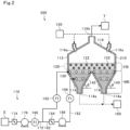
- FIG. 2 is a view for illustrating a hydrogen production apparatus 200 according to a modification example.
- the hydrogen production apparatus 200 includes an accommodating tank 210, the heating unit 120, the first diffuser tubes 130, the second diffuser tubes 140, the catalyst supply unit 150, the catalyst discharge unit 160, and the raw material gas supply unit 170.
- the shape of the accommodating tank 210 is different from that of the accommodating tank 110 of the hydrogen production apparatus 100, and other configurations are substantially the same as those of the hydrogen production apparatus 100.
- constituent elements that are substantially the same as those of the above-mentioned hydrogen production apparatus 100 are denoted by the same reference symbols, and description thereof is omitted.
- the accommodating tank 210 of the modification example includes one upper portion 112, a plurality of lower portions 114, and one lid portion 116.
- the lid portion 116 has a plurality of supply ports 116a formed therein. The number of the supply ports 116a may be equal to the number of the lower portions 114.
- the accommodating tank 110 includes only one lower portion 114 as in the above-mentioned hydrogen production apparatus 100
- the accommodating tank 210 of the hydrogen production apparatus 200 includes the plurality of lower portions 114.
- the height of the accommodating tank 210 can be reduced even when the upper portion 112 is increased in size in the horizontal direction with the inclination angle of each of the lower portions 114 being maintained while the bottom surface extending in the horizontal direction is eliminated.
- the height of the accommodating tank 210 can be reduced while the fluidized bed FB of the catalyst, that is, the reaction field for the pyrolysis reaction is enlarged.
- the treatment amount (pyrolysis amount) of the raw material gas per unit time can be increased by enlarging the reaction field for the pyrolysis reaction.
- the hydrogen production apparatus 200 according to the modification example can increase the production amount of hydrogen per unit time.
- the height of the accommodating tank 210 can be reduced.
- the construction cost of the accommodating tank 210 can be reduced.
- FIG. 3 is a diagram for illustrating a power generation system 500 according to this embodiment.
- the power generation system 500 includes the hydrogen production apparatus 100 and a power generation apparatus 510.
- the power generation apparatus 510 is, for example, a thermal power generation facility.
- the power generation apparatus 510 includes a boiler 512, a steam turbine 514, and a power generator 516.
- the hydrogen produced by the hydrogen production apparatus 100 and air are supplied to the boiler 512.
- the boiler 512 burns the hydrogen to generate steam.
- Fuel may be supplied to the boiler 512 in addition to the hydrogen.
- the fuel is, for example, coal.
- the steam generated by the boiler 512 is supplied to the steam turbine 514.
- the steam turbine 514 converts the energy of the steam into rotational energy.
- the power generator 516 converts the rotational energy transmitted from the steam turbine 514 into electric power.
- the power generation system 500 generates power through use of the hydrogen produced by the hydrogen production apparatus 100. As a result, the power generation system 500 can generate power at low cost.
- the power generation apparatus 510 may include a gas turbine instead of the boiler 512 or in addition to the boiler 512.
- the gas turbine burns the hydrogen produced by the hydrogen production apparatus 100 to generate rotational energy.
- the rotational energy generated by the gas turbine is then transmitted to the steam turbine 514.
- fuel may be supplied to the gas turbine in addition to the hydrogen.
- the fuel is, for example, a natural gas obtained by vaporizing a liquefied natural gas.
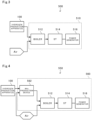
- FIG. 4 is a diagram for illustrating another power generation system 550 according to this embodiment.
- the power generation system 550 includes the hydrogen production apparatus 100 and a power generation apparatus 560.
- the power generation apparatus 560 is, for example, a thermal power generation facility.
- the power generation apparatus 560 includes an ammonia production device 562, the boiler 512, the steam turbine 514, and the power generator 516.
- the constituent elements that are substantially the same as those of the above-mentioned power generation system 500 are denoted by the same reference symbols, and description thereof is omitted.
- the hydrogen produced by the hydrogen production apparatus 100 and air are supplied to the ammonia production device 562.
- the ammonia production device 562 produces ammonia from hydrogen and nitrogen contained in air.
- the ammonia produced by the ammonia production device 562 is supplied to the boiler 512.
- the boiler 512 of the power generation apparatus 560 burns the ammonia to generate steam.
- Fuel may be supplied to the boiler 512 of the power generation apparatus 560 in addition to the ammonia.
- the fuel is, for example, coal.
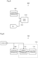
- the power generation apparatus 610 of the power generation system 600 includes a fuel cell 612.
- the fuel cell 612 includes a fuel electrode, an air electrode, and an electrolyte placed between the fuel electrode and the air electrode.
- the hydrogen produced by the hydrogen production apparatus 100 is supplied to the fuel electrode of the fuel cell 612.
- Air is supplied to the air electrode of the fuel cell 612.
- the fuel cell 612 generates electric power by reacting the hydrogen with oxygen contained in the air.
- the power generation system 600 generates power through use of the hydrogen produced by the hydrogen production apparatus 100. As a result, the power generation system 600 can generate power at low cost.
- FIG. 6 is a diagram for illustrating a steelmaking system 700 according to this embodiment.
- the steelmaking system 700 includes the hydrogen production apparatus 100 and a steelmaking apparatus 710.
- the hydrogen production apparatus 100 uses iron ore as a catalyst.
- the steelmaking apparatus 710 includes a direct reduction furnace 712 and an electric furnace 714.
- the hydrogen produced by the hydrogen production apparatus 100 and the iron ore are supplied to the direct reduction furnace 712.
- the direct reduction furnace 712 reduces the iron ore in a solid state with the hydrogen.
- the electric furnace 714 melts and refines the iron ore reduced by the direct reduction furnace 712. Thus, iron (e.g., steel) is produced.
- the steelmaking system 700 produces iron through use of the hydrogen produced by the hydrogen production apparatus 100.
- the steelmaking system 700 can produce iron while reducing carbon dioxide (CO 2 ) emission.
- FIG. 7 is a diagram for illustrating another steelmaking system 750 according to this embodiment.
- the steelmaking system 750 according to this embodiment includes the hydrogen production apparatus 100 and a steelmaking apparatus 760.
- the hydrogen production apparatus 100 uses iron ore as a catalyst.
- the steelmaking apparatus 760 of the steelmaking system 750 includes a blast furnace 762 and a converter 764.
- the hydrogen produced by the hydrogen production apparatus 100, the iron ore, and coke are supplied to the blast furnace 762.
- the blast furnace 762 reduces the iron ore while melting the iron ore to produce pig iron.
- the converter 764 converts the pig iron to steel. Thus, iron (e.g., steel) is produced.
- the steelmaking system 750 produces iron through use of the hydrogen produced by the hydrogen production apparatus 100.
- the steelmaking system 750 can produce iron while reducing carbon dioxide emission.
- the supply port 116a, the heating unit 120, the first diffuser tubes 130, the second diffuser tubes 140, and the discharge port 114a be placed in the stated order from above to below.
- FIG. 8 is a view for illustrating another example of the installation form of the first diffuser tubes 130.
- the hydrogen production apparatuses 100 and 200 may each include first first diffuser tubes 130A placed in parallel to the horizontal direction and second first diffuser tubes 130B placed in parallel to the horizontal direction so that the central axis directions thereof intersect with (for example, are orthogonal to) the first first diffuser tubes 130A.
- the hydrogen production apparatuses 100 and 200 may each include first second diffuser tubes 140 placed in parallel to the horizontal direction and second second diffuser tubes 140 placed in parallel to the horizontal direction so that the central axis directions thereof intersect with (for example, are orthogonal to) the first second diffuser tubes 140.
- the heating unit 120 may include first heating members 122 placed in parallel to the horizontal direction and second heating members 122 placed in parallel to the horizontal direction so that the central axis directions thereof intersect with (for example, are orthogonal to) the first heating members 122.
- the flow rate of the raw material gas to be supplied to the first diffuser tubes 130 by the raw material gas supply unit 170 is larger than the flow rate of the raw material gas to be supplied to the second diffuser tubes 140.
- the flow rate of the raw material gas to be supplied to the first diffuser tubes 130 by the raw material gas supply unit 170 may be equal to or smaller than the flow rate of the raw material gas to be supplied to the second diffuser tubes 140.
- the superficial velocity ratio U0/Umf of a total of the raw material gas diffused from the first diffuser tubes 130 and the raw material gas diffused from the second diffuser tubes 140 is 1.1 or more and 2.0 or less.
- the superficial velocity ratio U0/Umf of a total of the raw material gas diffused from the first diffuser tubes 130 and the raw material gas diffused from the second diffuser tubes 140 be 1.0 or more, or the superficial velocity ratio U0/Umf may be more than 2.0.
- the accommodating tanks 110 and 210 each include the upper portion 112 and the lower portion 114.
- the shapes of the accommodating tanks 110 and 210 there is no limitation on the shapes of the accommodating tanks 110 and 210.
- the plurality of heating members 122 are placed in two stages at different positions in the vertical direction.
- the plurality of heating members 122 may be placed in one stage or may be placed in three or more stages at different positions in the vertical direction. It is appropriate that the plurality of heating members 122 be placed in the number of stages corresponding to the layer height of the fluidized bed FB.
- FIG. 9 is a first view for illustrating another example of the shape of an accommodating tank 310.
- an upper portion 312 of the accommodating tank 310 includes a small-diameter portion 312a, a large-diameter portion 312b, and a radially expanding portion 312c.
- the small-diameter portion 312a is continuous with an upper end of the lower portion 114.
- the horizontal cross-section area of the internal space of the small-diameter portion 312a is substantially constant from above to below.
- the heating unit 120 and the first diffuser tubes 130 are placed in the small-diameter portion 312a.
- the fluidized bed FB is formed in the small-diameter portion 312a.
- the large-diameter portion 312b is placed above the small-diameter portion 312a.
- An upper end of the large-diameter portion 312b is continuous with the lid portion 116.
- the horizontal cross-section area of the internal space of the large-diameter portion 312b is substantially constant from above to below.
- the horizontal cross-section area of the internal space of the large-diameter portion 312b is larger than that of the small-diameter portion 312a.
- the radially expanding portion 312c is continuous with an upper end of the small-diameter portion 312a and a lower end of the large-diameter portion 312b.
- the horizontal cross-section area of the internal space of the radially expanding portion 312c is gradually increased from below to above.
- the upper portion 312 includes the small-diameter portion 312a, the large-diameter portion 312b, and the radially expanding portion 312c, the flow velocity of an upward airflow toward the exhaust port 116b can be reduced, and hence the scattering of the catalyst can be suppressed.
- FIG. 10 is a second view for illustrating another example of the shape of an accommodating tank 410.
- an upper portion 412 of the accommodating tank 410 includes a large-diameter portion 412a, a small-diameter portion 412b, a large-diameter portion 412c, a radially contracting portion 412d, and a radially expanding portion 412e.
- the large-diameter portion 412a is continuous with the upper end of the lower portion 114.
- the horizontal cross-section area of the internal space of the large-diameter portion 412a is substantially constant from above to below.
- the heating unit 120 and the first diffuser tubes 130 are placed in the large-diameter portion 412a.
- the fluidized bed FB is formed in the large-diameter portion 412a.
- the small-diameter portion 412b is placed above the large-diameter portion 412a.
- the horizontal cross-section area of the internal space of the small-diameter portion 412b is smaller than that of the large-diameter portion 412a.
- the radially contracting portion 412d is continuous with an upper end of the large-diameter portion 412a and a lower end of the small-diameter portion 412b.
- the horizontal cross-section area of the internal space of the radially contracting portion 412d is gradually decreased from below to above.
- the large-diameter portion 412c is placed above the small-diameter portion 412b.
- An upper end of the large-diameter portion 412c is continuous with the lid portion 116.
- the horizontal cross-section area of the internal space of the large-diameter portion 412c is larger than that of the small-diameter portion 412b.
- the radially expanding portion 412e is continuous with an upper end of the small-diameter portion 412b and a lower end of the large-diameter portion 412c.
- the horizontal cross-section area of the internal space of the radially expanding portion 412e is gradually increased from below to above.
- the diffusion flow rate is allowed to have a difference in the horizontal direction, and for example, when the diffusion flow rate in a central portion is reduced and the diffusion flow rate in an outer peripheral portion of the central portion is increased, the catalyst can be concentrated in the center.
- the above-mentioned power generation systems 500, 550, and 600 may each include the hydrogen production apparatus 200 instead of the hydrogen production apparatus 100.
- the above-mentioned steelmaking systems 700 and 750 may each include the hydrogen production apparatus 200 instead of the hydrogen production apparatus 100.
- the hydrogen produced by the hydrogen production apparatuses 100 and 200 may be supplied to a gas pipeline.
- the present disclosure can contribute to, for example, Goal 7 "Ensure access to affordable, reliable, sustainable and modern energy for all” in sustainable Development Goals (SDGs).
- SDGs Sustainable Development Goals
- FB fluidized bed
- MB moving bed
- 100 hydrogen production apparatus
- 110 accommodating tank
- 112 upper portion
- 114 lower portion
- 114a discharge port
- 116a supply port
- 120 heating unit
- 130 first diffuser tube
- 140 second diffuser tube
- 150 catalyst supply unit
- 160 catalyst discharge unit
- 170 raw material gas supply unit
- 200 hydrogen production apparatus
- 210 accommodating tank
- 310 accommodating tank
- 312 upper portion
- 410 accommodating tank
- 412 upper portion
- 510 power generation apparatus
- 550 power generation system
- 560 power generation apparatus
- 600 power generation system
- 610 power generation apparatus
- 700 steelmaking system
- 710 steelmaking apparatus
- 750 steelmaking system
- 760 steelmaking apparatus
Landscapes
- Chemical & Material Sciences (AREA)
- Organic Chemistry (AREA)
- Engineering & Computer Science (AREA)
- Combustion & Propulsion (AREA)
- Chemical Kinetics & Catalysis (AREA)
- Health & Medical Sciences (AREA)
- General Health & Medical Sciences (AREA)
- Inorganic Chemistry (AREA)
- Materials Engineering (AREA)
- Devices And Processes Conducted In The Presence Of Fluids And Solid Particles (AREA)
- Hydrogen, Water And Hydrids (AREA)
- Catalysts (AREA)
Abstract
Description
- The present disclosure relates to a hydrogen production apparatus, a power generation system, and a steelmaking system. This application claims the benefit of priority to
Japanese Patent Application No. 2022-073628 filed on April 27, 2022 - As a technology for producing hydrogen, there has been known a technology for subjecting hydrocarbon, such as methane, to steam reforming. However, the steam reforming of hydrocarbon produces carbon dioxide in a production process of hydrogen. Thus, it is conceived to produce hydrogen without emitting carbon dioxide by subjecting hydrocarbon to pyrolysis to generate carbon as a solid.
- As a technology for subjecting hydrocarbon to pyrolysis, there is a disclosure of an apparatus including a reaction furnace, a raw material gas supply source, and a heating unit provided outside the reaction furnace (e.g., Patent Literature 1). The reaction furnace accommodates a catalyst. The raw material gas supply source supplies hydrocarbon to the reaction furnace. The heating unit is provided on the periphery of the reaction furnace and heats the inside of the reaction furnace.
- [PTL 1]
JP 5862559 B2 - The pyrolysis reaction of hydrocarbon progresses efficiently at 800°C or more through use of a catalyst. However, the pyrolysis reaction of hydrocarbon is an endothermic reaction, and hence it is required to supply heat from outside. Thus, in the technology for heating the reaction furnace from outside as in Patent Literature 1 described above, it is required to heat a furnace wall of the reaction furnace to at least an inside temperature(for example, 1,000°C or more) in order to heat the inside of the reaction furnace to 800°C or more. Then, the reaction furnace needs to be formed of a material such as an expensive heat-resistant alloy having satisfactory heat conductivity while having a heat resistance of 1,000°C or more, causing a problem in that the cost for a heating apparatus and the reaction furnace is increased. In addition, in the technology of heating the reaction furnace from outside, the catalyst in the reaction furnace is heated from a wall surface, and hence a temperature difference occurs between the vicinity of the wall surface and the central portion when the volume of the catalyst becomes large. Thus, it is difficult to uniformly and efficiently decompose hydrocarbon in the reaction furnace, and hence it is difficult to increase the size of the reaction furnace.
- In view of the above-mentioned problem, the present disclosure has an object to provide a hydrogen production apparatus, a power generation system, and a steelmaking system that are capable of subjecting hydrocarbon to pyrolysis at low cost.
- In order to solve the above-mentioned problem, according to one aspect of the present disclosure, there is provided a hydrogen production apparatus, including: an accommodating tank; a heating unit placed in the accommodating tank; a first diffuser tube placed below the heating unit in the accommodating tank; a second diffuser tube placed below the first diffuser tube in the accommodating tank; a catalyst supply unit that supplies a catalyst containing any one or more of iron, nickel, copper, and aluminum from a supply port formed above the heating unit in the accommodating tank; a catalyst discharge unit that discharges the catalyst from a discharge port formed below the second diffuser tube in the accommodating tank; and a raw material gas supply unit that supplies a raw material gas containing at least hydrocarbon to the first diffuser tube and the second diffuser tube.
- Further, a flow rate of the raw material gas to be supplied to the first diffuser tube by the raw material gas supply unit may be larger than a flow rate of the raw material gas to be supplied to the second diffuser tube.
- Further, a superficial velocity ratio UO/Umf of a total of the raw material gas diffused from the first diffuser tube and the raw material gas diffused from the second diffuser tube may be 1.1 or more and 2.0 or less.
- Further, in the accommodating tank, a fluidized bed of the catalyst may be formed above the first diffuser tube, and a moving bed of the catalyst may be formed below the first diffuser tube.
- Further, the accommodating tank may include: an upper portion having a tubular shape; and a lower portion, which is formed below the upper portion, and in which a horizontal cross-section area of an internal space is gradually decreased from above to below. The heating unit may be placed in the upper portion. The second diffuser tube may be placed in the lower portion.
- Further, the accommodating tank may include one upper portion and a plurality of lower portions.
- In order to solve the above-mentioned problem, according to one aspect of the present disclosure, there is provided a power generation system, including: a hydrogen production apparatus including: an accommodating tank; a heating unit placed in the accommodating tank; a first diffuser tube placed below the heating unit in the accommodating tank; a second diffuser tube placed below the first diffuser tube in the accommodating tank; a catalyst supply unit that supplies a catalyst containing any one or more of iron, nickel, copper, and aluminum from a supply port formed above the heating unit in the accommodating tank; a catalyst discharge unit that discharges the catalyst from a discharge port formed below the second diffuser tube in the accommodating tank; and a raw material gas supply unit that supplies a raw material gas containing at least hydrocarbon to the first diffuser tube and the second diffuser tube; and a power generation apparatus that generates power through use of hydrogen produced by the hydrogen production apparatus.
- In order to solve the above-mentioned problem, according to one aspect of the present disclosure, there is provided a steelmaking system, including: a hydrogen production apparatus including: an accommodating tank; a heating unit placed in the accommodating tank; a first diffuser tube placed below the heating unit in the accommodating tank; a second diffuser tube placed below the first diffuser tube in the accommodating tank; a catalyst supply unit that supplies a catalyst containing any one or more of iron, nickel, copper, and aluminum from a supply port formed above the heating unit in the accommodating tank; a catalyst discharge unit that discharges the catalyst from a discharge port formed below the second diffuser tube in the accommodating tank; and a raw material gas supply unit that supplies a raw material gas containing at least hydrocarbon to the first diffuser tube and the second diffuser tube; and a steelmaking apparatus that produces iron through use of hydrogen produced by the hydrogen production apparatus.
- According to the present disclosure, it is possible to subject hydrocarbon to pyrolysis at low cost.
-
-
FIG. 1 is a view for schematically illustrating a hydrogen production apparatus according to an embodiment. -
FIG. 2 is a view for illustrating a hydrogen production apparatus according to a modification example. -
FIG. 3 is a diagram for illustrating a power generation system according to an embodiment. -
FIG. 4 is a diagram for illustrating another power generation system according to an embodiment. -
FIG. 5 is a diagram for illustrating another power generation system according to an embodiment. -
FIG. 6 is a diagram for illustrating a steelmaking system according to an embodiment. -
FIG. 7 is a diagram for illustrating another steelmaking system according to an embodiment. -
FIG. 8 is a view for illustrating another example of the installation form of first diffuser tubes. -
FIG. 9 is a first view for illustrating another example of the shape of an accommodating tank. -
FIG. 10 is a second view for illustrating another example of the shape of the accommodating tank. - Now, with reference to the attached drawings, embodiments of the present disclosure are described in detail. The dimensions, materials, and other specific numerical values represented in the embodiment are merely examples used for facilitating the understanding of the disclosure, and do not limit the present disclosure unless otherwise particularly noted. Elements having substantially the same functions and configurations herein and in the drawings are denoted by the same reference symbols to omit redundant description thereof. Further, illustration of elements with no direct relationship to the present disclosure is omitted.
-
FIG. 1 is a view for schematically illustrating ahydrogen production apparatus 100 according to this embodiment. InFIG. 1 , the solid arrows indicate flows of a raw material gas and a generated gas. InFIG. 1 , the dashed line arrows indicate flows of a catalyst and solid carbon. In addition, inFIG. 1 , aheating unit 120 is indicated by hatching. - As illustrated in
FIG. 1 , thehydrogen production apparatus 100 includes anaccommodating tank 110, theheating unit 120, afirst diffuser tube 130, asecond diffuser tube 140, acatalyst supply unit 150, acatalyst discharge unit 160, and a raw materialgas supply unit 170. - The
accommodating tank 110 is a container (hopper) that temporarily accommodates a catalyst. Theaccommodating tank 110 has a tubular shape and is installed so that the central axis direction thereof is in a vertical direction. In this embodiment, theaccommodating tank 110 includes anupper portion 112, alower portion 114, and alid portion 116. - The
upper portion 112 is a portion having a tubular shape, such as a cylinder, an elliptical cylinder, or a rectangular tube. The horizontal cross-section area of the internal space of theupper portion 112 is, for example, substantially constant from above to below. - The
lower portion 114 is a portion formed below theupper portion 112. The horizontal cross-section area of the internal space of thelower portion 114 is gradually decreased from above to below. For example, thelower portion 114 is a tube having a cone shape in which the inner diameter is gradually decreased from above to below. An inclination angle θ of thelower portion 114 is, for example, 60 degrees. - The
lid portion 116 is a portion formed above theupper portion 112. The horizontal cross-section area of the internal space of thelid portion 116 is gradually increased from above to below. For example, thelid portion 116 is a tube having a cone shape in which the inner diameter is gradually increased from above to below. - The catalyst to be accommodated in the
accommodating tank 110 is a catalyst that accelerates the pyrolysis reaction represented by the following formula (1).
CH4→C+2H2 ··· Formula (1)
- The catalyst contains any one or more of iron, nickel, copper, and aluminum. In this embodiment, the catalyst is a natural mineral, for example, iron ore. The catalyst is not required to be a natural mineral as long as the catalyst contains any one or more of iron, nickel, copper and aluminum. The particle size of the catalyst is, for example, 50 µm or more and 1,000 µm or less, preferably 100 µm or more and 300 µm or less.
- The
heating unit 120 is placed in theupper portion 112 forming theaccommodating tank 110. Theheating unit 120 heats the catalyst to a temperature at which the pyrolysis reaction represented by the above-mentioned formula (1) is efficiently accelerated. Theheating unit 120 heats the catalyst so that the temperature of the catalyst becomes, for example, 800°C or more and 900°C or less. In this embodiment, theheating unit 120 includes a plurality ofheating members 122. Theheating members 122 each have, for example, a columnar shape or a cylindrical shape. The plurality ofheating members 122 are installed in theupper portion 112 so that the central axis directions thereof are in a horizontal direction. The plurality ofheating members 122 are placed substantially evenly in theupper portion 112. In this embodiment, the plurality ofheating members 122 are placed in parallel to the horizontal direction. In addition, in this embodiment, the plurality ofheating members 122 are placed in two stages at different positions in the vertical direction. - The
heating unit 120 is formed of, for example, an electric heater or a heat transfer tube. When theheating unit 120 is formed of an electric heater, theheating unit 120 includes, for example, a heat transfer body (ceramic) having a columnar shape and a heat generator built in the heat transfer body. In addition, it is appropriate that one or both of electric power generated by renewable energy and electric power generated by nuclear power generation be supplied to the electric heater. In addition, when theheating unit 120 is formed of a heat transfer tube, a heat medium that passes through the inside of the heat transfer tube is, for example, a combustion exhaust gas. - The
first diffuser tube 130 is placed below theheating unit 120 in theaccommodating tank 110. In this embodiment, thefirst diffuser tube 130 is placed in theupper portion 112. A plurality offirst diffuser tubes 130 are placed. The plurality offirst diffuser tubes 130 are placed in theupper portion 112 so that the central axis directions thereof are in the horizontal direction. In this embodiment, the plurality offirst diffuser tubes 130 are placed in parallel to the horizontal direction. A plurality of holes are formed in each of thefirst diffuser tubes 130. - The
second diffuser tube 140 is placed below thefirst diffuser tubes 130 in theaccommodating tank 110. In this embodiment, thesecond diffuser tube 140 is placed in thelower portion 114 forming theaccommodating tank 110. In this embodiment, a plurality ofsecond diffuser tubes 140 are placed. The plurality ofsecond diffuser tubes 140 are placed in thelower portion 114 so that the central axis directions thereof are in the horizontal direction. In this embodiment, the plurality ofsecond diffuser tubes 140 are placed in parallel to the horizontal direction. A plurality of holes are formed in each of thesecond diffuser tubes 140. - The
catalyst supply unit 150 supplies the catalyst from asupply port 116a formed in thelid portion 116. - The
catalyst discharge unit 160 discharges the catalyst from adischarge port 114a formed on a bottom surface of thelower portion 114. - The raw material
gas supply unit 170 supplies a raw material gas to thefirst diffuser tubes 130 and thesecond diffuser tubes 140. The raw material gas is a gas containing at least hydrocarbon (e.g., methane). The raw material gas is, for example, a natural gas obtained by vaporizing a liquefied natural gas (LNG). - In this embodiment, the raw material
gas supply unit 170 includes afirst supply tube 172, a flowrate adjustment valve 174, afirst blower 176, asecond supply tube 182, a flowrate adjustment valve 184, asecond blower 186, andflowmeters - The
first supply tube 172 is a pipe that connects a supply source S of the raw material gas and thefirst diffuser tubes 130 to each other. Thefirst supply tube 172 includes the flowrate adjustment valve 174 and thefirst blower 176. - The flow
rate adjustment valve 174 adjusts the opening degree of a flow path formed in thefirst supply tube 172. The flowrate adjustment valve 174 is, for example, a butterfly valve. - The
first blower 176 is placed between the flowrate adjustment valve 174 in thefirst supply tube 172 and thefirst diffuser tubes 130. The suction side of thefirst blower 176 is connected to the flowrate adjustment valve 174. The ejection side of thefirst blower 176 is connected to thefirst diffuser tubes 130. Thefirst blower 176 boosts the pressure of the raw material gas. - The
second supply tube 182 is a pipe branched from between thefirst blower 176 in thefirst supply tube 172 and thefirst diffuser tubes 130 and connected to thesecond diffuser tubes 140. Thesecond supply tube 182 includes a flowrate adjustment valve 184 and asecond blower 186. - The flow
rate adjustment valve 184 adjusts the opening degree of a flow path formed in thesecond supply tube 182. The flowrate adjustment valve 184 is, for example, a butterfly valve. - The
second blower 186 is placed between the flowrate adjustment valve 184 in thesecond supply tube 182 and thesecond diffuser tubes 140. The suction side of thesecond blower 186 is connected to the flowrate adjustment valve 184. The ejection side of thesecond blower 186 is connected to thesecond diffuser tubes 140. Thesecond blower 186 further boosts the pressure of the raw material gas having the pressure boosted by thefirst blower 176. - The
flowmeter 190 detects a flow rate QT of the raw material gas ejected from thefirst blower 176. Theflowmeter 192 detects a flow rate Q1 of the raw material gas supplied to thefirst diffuser tubes 130. Theflowmeter 194 detects a flow rate Q2 of the raw material gas to be supplied to thesecond diffuser tubes 140. Flow rate QT=flow rate Q1+flow rate Q2 is established. - The opening degree of the flow
rate adjustment valve 174 and the ejection pressures of thefirst blower 176 and thesecond blower 186 are set so that the superficial velocity ratio U0/Umf of a total of the raw material gas diffused from thefirst diffuser tubes 130 and the raw material gas diffused from thesecond diffuser tubes 140 becomes 1.1 or more and 2.0 or less, preferably 1.1 or more and 1.5 or less. U0 represents the velocity at which the raw material gas moves inside a fluidized bed FB. Umf represents the fluidization start velocity (minimum fluidization velocity). - In addition, the opening degree of the flow
rate adjustment valve 184 is set so that the flow rate Q1) of the raw material gas to be supplied to thefirst diffuser tubes 130 becomes larger than the flow rate Q2 of the raw material gas to be supplied to thesecond diffuser tubes 140. In this embodiment, the opening degree of the flowrate adjustment valve 184 is set so that the ratio between the flow rate Q1 and the flow rate Q2 satisfies flow rate Q1:flow rate Q2=7:3. - Next, the flows of the catalyst and the raw material gas in the above-mentioned
hydrogen production apparatus 100 are described. As described above, in thehydrogen production apparatus 100, thecatalyst supply unit 150 supplies the catalyst to theaccommodating tank 110, and thecatalyst discharge unit 160 discharges the catalyst from theaccommodating tank 110. Thus, the catalyst moves inside theaccommodating tank 110 from above to below by its own weight. As a result, a moving bed of the catalyst is formed in theaccommodating tank 110. - In addition, the
hydrogen production apparatus 100 includes thefirst diffuser tubes 130, thesecond diffuser tubes 140, and the raw materialgas supply unit 170. Then, the raw materialgas supply unit 170 supplies the raw material gas to thefirst diffuser tubes 130 and thesecond diffuser tubes 140 so that the superficial velocity ratio U0/Umf of a total of the raw material gas diffused from thefirst diffuser tubes 130 and the raw material gas diffused from thesecond diffuser tubes 140 becomes 1.1 or more and 2.0 or less. As a result, thehydrogen production apparatus 100 can form the fluidized bed FB of the catalyst above thefirst diffuser tubes 130 and the moving bed MB of the catalyst below thefirst diffuser tubes 130 in theaccommodating tank 110. Thus, the catalyst supplied from thecatalyst supply unit 150 forms the moving bed MB after forming the fluidized bed FB, and is discharged by thecatalyst discharge unit 160. - The
catalyst supply unit 150 supplies the catalyst and thecatalyst discharge unit 160 discharges the catalyst, so that the upper surface of the fluidized bed FB is maintained at a predetermined position above theheating unit 120. In addition, the residence time period of the catalyst in theaccommodating tank 110 can be controlled by controlling the supply flow rate of the catalyst by thecatalyst supply unit 150 and the discharge flow rate of the catalyst by thecatalyst discharge unit 160. - In addition, the
heating unit 120 is placed above thefirst diffuser tubes 130. As a result, theheating unit 120 is arranged in the fluidized bed FB of the catalyst. Thus, the fluidized bed FB of the catalyst is heated by theheating unit 120. - Then, the raw material gas diffused from the
first diffuser tubes 130 and thesecond diffuser tubes 140 is heated by the catalyst (convection heat transfer) in the process of passing through the fluidized bed FB of the catalyst. As a result, the pyrolysis reaction represented by the above-mentioned formula (1) progresses, and hydrogen and solid carbon are generated from the hydrocarbon contained in the raw material gas. That is, the main pyrolysis reaction progresses in the fluidized bed FB. - The hydrogen generated as described above and the unreacted raw material gas are fed to a gas treatment facility T in a subsequent stage through an
exhaust port 116b formed in thelid portion 116. - Meanwhile, the solid carbon generated by the pyrolysis reaction adheres to the surface of the catalyst. Thus, the solid carbon moves together with the catalyst from the fluidized bed FB to the moving bed MB by their own weight . Then, the solid carbon forms the moving bed MB together with the catalyst, and is finally discharged to outside by the
catalyst discharge unit 160. The catalyst discharged to outside and having the solid carbon adhering thereto may be supplied to theaccommodating tank 110 again by thecatalyst supply unit 150. In addition, the catalyst having the solid carbon adhering thereto may be separated into the catalyst and the solid carbon. The separated catalyst may be supplied to theaccommodating tank 110 again by thecatalyst supply unit 150. - In addition, the
second diffuser tubes 140 are placed below thefirst diffuser tubes 130. As a result, thesecond diffuser tubes 140 are arranged in the moving bed MB of the catalyst. Thus, the raw material gas diffused from thesecond diffuser tubes 140 undergoes heat exchange with the catalyst forming the moving bed MB. As a result, the raw material gas is heated, and the catalyst is cooled. - As described above, the
hydrogen production apparatus 100 according to this embodiment forms the fluidized bed FB of the catalyst above thefirst diffuser tubes 130 in theaccommodating tank 110, and forms the moving bed MB of the catalyst below thesecond diffuser tubes 140. As a result, thehydrogen production apparatus 100 can cause the catalyst after the reaction to continuously move from the fluidized bed FB to the moving bed MB while continuously bringing the catalyst and the raw material gas into contact with each other to continuously perform the pyrolysis reaction of the raw material gas in the fluidized bed FB. That is, thehydrogen production apparatus 100 according to this embodiment can continuously replace the catalyst in the fluidized bed FB while continuously performing the pyrolysis reaction of the raw material gas. Thus, in the fluidized bed FB, a new catalyst and the raw material gas are constantly brought into contact with each other, and hence the pyrolysis reaction can be efficiently progressed. - In addition, in the
hydrogen production apparatus 100 according to this embodiment, theheating unit 120 is placed evenly in the fluidized bed FB, and hence the catalyst is substantially uniformly heated by theheating unit 120 in the fluidized bed FB. Accordingly, thehydrogen production apparatus 100 is not required to heat theaccommodating tank 110 from outside. As a result, in thehydrogen production apparatus 100, a furnace wall of theaccommodating tank 110 is not required to be formed of a high-grade material such as a heat-resistant alloy having a heat resistance of 1,000°C or more and high heat conductivity. Thus, a furnace installation structure using a carbon steel plate lined with a refractory material can be applied to thehydrogen production apparatus 100, and hence the manufacturing cost of theaccommodating tank 110 can be reduced. As a result, thehydrogen production apparatus 100 can subject hydrocarbon to pyrolysis at low cost. In other words, thehydrogen production apparatus 100 can produce hydrogen at low cost. - In addition, with the conventional art of heating the inside of the accommodating tank from outside, it is difficult to make the internal temperature of the accommodating tank (temperature of the catalyst) uniform, and hence it is difficult to increase the size of the accommodating tank. Meanwhile, in the
hydrogen production apparatus 100, theheating unit 120 is evenly placed in the fluidized bed FB, and hence the temperature of the fluidized bed FB in theaccommodating tank 110 can be made uniform as compared to the conventional art of heating the inside of the accommodating tank from outside. Thus, thehydrogen production apparatus 100 can avoid the situation in which the temperature of the catalyst is locally decreased in the fluidized bed FB. Accordingly, thehydrogen production apparatus 100 can efficiently subject hydrocarbon to pyrolysis. In addition, thehydrogen production apparatus 100 can make the temperature of the fluidized bed FB uniform, and hence the size of theaccommodating tank 110 can also be increased. Thus, thehydrogen production apparatus 100 can produce a large amount of hydrogen at low cost. - In addition, as described above, the
hydrogen production apparatus 100 subjects the raw material gas to pyrolysis to generate hydrogen and solid carbon. Thus, thehydrogen production apparatus 100 can produce hydrogen without emitting carbon dioxide derived from the raw material gas. - In addition, as described above, the superficial velocity ratio U0/Umf of a total of the raw material gas diffused from the
first diffuser tubes 130 and the raw material gas diffused from thesecond diffuser tubes 140 is 1.1 or more and 2.0 or less. As a result, the wear of theheating unit 120 caused by the catalyst can be suppressed. Thus, the durability of theheating unit 120 can be improved. - In addition, as described above, the
second diffuser tubes 140 are placed in the moving bed MB of the catalyst. As a result, the heat exchange can be performed between the raw material gas diffused from thesecond diffuser tubes 140 and the catalyst forming the moving bed MB. Accordingly, the raw material gas can be preheated (convection heat transfer) with the heat of the catalyst forming the moving bed MB. Thus, the heating energy with which the catalyst is heated by theheating unit 120 can be reduced. In addition, the catalyst forming the moving bed MB is cooled to from about 200°C to about 300°C by the raw material gas. As a result, the deterioration of thecatalyst discharge unit 160 due to the heat of the catalyst can be suppressed. - In addition, the
first diffuser tubes 130 and thesecond diffuser tubes 140 are placed in the moving bed MB. As a result, the wear of thefirst diffuser tubes 130 and thesecond diffuser tubes 140 caused by the catalyst can be reduced. - In addition, as described above, the flow rate of the raw material gas to be supplied to the
first diffuser tubes 130 by the raw materialgas supply unit 170 is larger than the flow rate of the raw material gas to be supplied to thesecond diffuser tubes 140 by the raw materialgas supply unit 170. The pressure loss of thefirst blower 176 is increased when the layer height of the catalyst located above thefirst diffuser tubes 130 is increased. Similarly, the pressure loss of thesecond blower 186 is increased when the layer height of the catalyst located above thesecond diffuser tubes 140 is increased. Thus, when the flow rate of the raw material gas to be supplied to thefirst diffuser tubes 130 in which the layer height of the catalyst located above thefirst diffuser tubes 130 is relatively low is set to be larger than the flow rate of the raw material gas to be supplied to thesecond diffuser tubes 140 in which the layer height of the catalyst located above thesecond diffuser tubes 140 is relatively high, the motive power of thesecond blower 186 can be reduced. - In addition, as described above, the horizontal cross-section area of the internal space of the
lower portion 114 of theaccommodating tank 110 is gradually decreased from above to below. As a result, the catalyst can be caused to move smoothly in thelower portion 114. Thus, the places in thelower portion 114 in which the catalyst stagnates can be reduced. -
FIG. 2 is a view for illustrating ahydrogen production apparatus 200 according to a modification example. As illustrated inFIG. 2 , thehydrogen production apparatus 200 includes anaccommodating tank 210, theheating unit 120, thefirst diffuser tubes 130, thesecond diffuser tubes 140, thecatalyst supply unit 150, thecatalyst discharge unit 160, and the raw materialgas supply unit 170. In thehydrogen production apparatus 200 according to the modification example, the shape of theaccommodating tank 210 is different from that of theaccommodating tank 110 of thehydrogen production apparatus 100, and other configurations are substantially the same as those of thehydrogen production apparatus 100. Thus, constituent elements that are substantially the same as those of the above-mentionedhydrogen production apparatus 100 are denoted by the same reference symbols, and description thereof is omitted. - The
accommodating tank 210 of the modification example includes oneupper portion 112, a plurality oflower portions 114, and onelid portion 116. In the modification example, thelid portion 116 has a plurality ofsupply ports 116a formed therein. The number of thesupply ports 116a may be equal to the number of thelower portions 114. - In a case in which the
accommodating tank 110 includes only onelower portion 114 as in the above-mentionedhydrogen production apparatus 100, when an attempt is made to increase the size of theupper portion 112 in the horizontal direction with the inclination angle of thelower portion 114 being maintained while the bottom surface extending in the horizontal direction is eliminated in order to reduce the places in theupper portion 112 in which the catalyst stagnates, the entire height of theaccommodating tank 110 is increased. In view of the foregoing, theaccommodating tank 210 of thehydrogen production apparatus 200 according to the modification example includes the plurality oflower portions 114. As a result, the height of theaccommodating tank 210 can be reduced even when theupper portion 112 is increased in size in the horizontal direction with the inclination angle of each of thelower portions 114 being maintained while the bottom surface extending in the horizontal direction is eliminated. Thus, the height of theaccommodating tank 210 can be reduced while the fluidized bed FB of the catalyst, that is, the reaction field for the pyrolysis reaction is enlarged. - In the
hydrogen production apparatus 200 according to the modification example, the treatment amount (pyrolysis amount) of the raw material gas per unit time can be increased by enlarging the reaction field for the pyrolysis reaction. Thus, thehydrogen production apparatus 200 according to the modification example can increase the production amount of hydrogen per unit time. - In addition, in the
hydrogen production apparatus 200 according to the modification example, the height of theaccommodating tank 210 can be reduced. As a result, in thehydrogen production apparatus 200 according to the modification example, the construction cost of theaccommodating tank 210 can be reduced. -
FIG. 3 is a diagram for illustrating apower generation system 500 according to this embodiment. As illustrated inFIG. 3 , thepower generation system 500 includes thehydrogen production apparatus 100 and apower generation apparatus 510. Thepower generation apparatus 510 is, for example, a thermal power generation facility. Thepower generation apparatus 510 includes aboiler 512, asteam turbine 514, and apower generator 516. - The hydrogen produced by the
hydrogen production apparatus 100 and air are supplied to theboiler 512. Theboiler 512 burns the hydrogen to generate steam. Fuel may be supplied to theboiler 512 in addition to the hydrogen. The fuel is, for example, coal. - The steam generated by the
boiler 512 is supplied to thesteam turbine 514. Thesteam turbine 514 converts the energy of the steam into rotational energy. - The
power generator 516 converts the rotational energy transmitted from thesteam turbine 514 into electric power. - As described above, the
power generation system 500 according to this embodiment generates power through use of the hydrogen produced by thehydrogen production apparatus 100. As a result, thepower generation system 500 can generate power at low cost. - The
power generation apparatus 510 may include a gas turbine instead of theboiler 512 or in addition to theboiler 512. In this case, the gas turbine burns the hydrogen produced by thehydrogen production apparatus 100 to generate rotational energy. The rotational energy generated by the gas turbine is then transmitted to thesteam turbine 514. In addition, fuel may be supplied to the gas turbine in addition to the hydrogen. The fuel is, for example, a natural gas obtained by vaporizing a liquefied natural gas. -
FIG. 4 is a diagram for illustrating anotherpower generation system 550 according to this embodiment. As illustrated inFIG. 4 , thepower generation system 550 includes thehydrogen production apparatus 100 and apower generation apparatus 560. Thepower generation apparatus 560 is, for example, a thermal power generation facility. Thepower generation apparatus 560 includes anammonia production device 562, theboiler 512, thesteam turbine 514, and thepower generator 516. The constituent elements that are substantially the same as those of the above-mentionedpower generation system 500 are denoted by the same reference symbols, and description thereof is omitted. - The hydrogen produced by the
hydrogen production apparatus 100 and air are supplied to theammonia production device 562. Theammonia production device 562 produces ammonia from hydrogen and nitrogen contained in air. The ammonia produced by theammonia production device 562 is supplied to theboiler 512. - The
boiler 512 of thepower generation apparatus 560 burns the ammonia to generate steam. Fuel may be supplied to theboiler 512 of thepower generation apparatus 560 in addition to the ammonia. The fuel is, for example, coal. - As described above, the
power generation system 550 according to this embodiment generates power through use of the hydrogen produced by thehydrogen production apparatus 100. As a result, thepower generation system 550 can generate power at low cost. - In the same way as in the
power generation apparatus 510, thepower generation apparatus 560 may include a gas turbine instead of theboiler 512 or in addition to theboiler 512. In this case, the gas turbine burns the ammonia produced by theammonia production device 562 to generate rotational energy. The rotational energy generated by the gas turbine is then transmitted to thesteam turbine 514. In addition, fuel may be supplied to the gas turbine in addition to the ammonia. The fuel is, for example, a natural gas obtained by vaporizing a liquefied natural gas. -
FIG. 5 is a diagram for illustrating anotherpower generation system 600 according to this embodiment. As illustrated inFIG. 5 , thepower generation system 600 includes thehydrogen production apparatus 100 and apower generation apparatus 610. - The
power generation apparatus 610 of thepower generation system 600 includes afuel cell 612. Thefuel cell 612 includes a fuel electrode, an air electrode, and an electrolyte placed between the fuel electrode and the air electrode. The hydrogen produced by thehydrogen production apparatus 100 is supplied to the fuel electrode of thefuel cell 612. Air is supplied to the air electrode of thefuel cell 612. Thefuel cell 612 generates electric power by reacting the hydrogen with oxygen contained in the air. - As described above, the
power generation system 600 according to this embodiment generates power through use of the hydrogen produced by thehydrogen production apparatus 100. As a result, thepower generation system 600 can generate power at low cost. -
FIG. 6 is a diagram for illustrating asteelmaking system 700 according to this embodiment. As illustrated inFIG. 6 , thesteelmaking system 700 includes thehydrogen production apparatus 100 and asteelmaking apparatus 710. In this embodiment, thehydrogen production apparatus 100 uses iron ore as a catalyst. - The
steelmaking apparatus 710 includes adirect reduction furnace 712 and anelectric furnace 714. - The hydrogen produced by the
hydrogen production apparatus 100 and the iron ore are supplied to thedirect reduction furnace 712. Thedirect reduction furnace 712 reduces the iron ore in a solid state with the hydrogen. - The
electric furnace 714 melts and refines the iron ore reduced by thedirect reduction furnace 712. Thus, iron (e.g., steel) is produced. - As described above, the
steelmaking system 700 according to this embodiment produces iron through use of the hydrogen produced by thehydrogen production apparatus 100. As a result, thesteelmaking system 700 can produce iron while reducing carbon dioxide (CO2) emission. -
FIG. 7 is a diagram for illustrating anothersteelmaking system 750 according to this embodiment. As illustrated inFIG. 7 , thesteelmaking system 750 according to this embodiment includes thehydrogen production apparatus 100 and asteelmaking apparatus 760. In this embodiment, thehydrogen production apparatus 100 uses iron ore as a catalyst. - The
steelmaking apparatus 760 of thesteelmaking system 750 includes ablast furnace 762 and aconverter 764. The hydrogen produced by thehydrogen production apparatus 100, the iron ore, and coke are supplied to theblast furnace 762. Theblast furnace 762 reduces the iron ore while melting the iron ore to produce pig iron. Theconverter 764 converts the pig iron to steel. Thus, iron (e.g., steel) is produced. - As described above, the
steelmaking system 750 according to this embodiment produces iron through use of the hydrogen produced by thehydrogen production apparatus 100. As a result, thesteelmaking system 750 can produce iron while reducing carbon dioxide emission. - The embodiments have been described above with reference to the attached drawings, but, needless to say, the present disclosure is not limited to the embodiments. It is apparent that those skilled in the art may arrive at various alterations and modifications within the scope of claims, and those examples are construed as naturally falling within the technical scope of the present disclosure.
- For example, in the above-mentioned embodiments and the modification example, there has been given, as an example, the case in which the
heating unit 120 is placed in theupper portion 112. However, there is no limitation on the installation position of theheating unit 120 as long as theheating unit 120 is placed above thefirst diffuser tubes 130 in each of theaccommodating tanks - Similarly, in the above-mentioned embodiments and the modification example, there has been given, as an example, the case in which the
first diffuser tubes 130 are placed in theupper portion 112. However, there is no limitation on the installation position of thefirst diffuser tubes 130 as long as thefirst diffuser tubes 130 are placed between theheating unit 120 and thesecond diffuser tubes 140 in each of theaccommodating tanks - Similarly, in the above-mentioned embodiments and the modification example, there has been given, as an example, the case in which the
second diffuser tubes 140 are placed in thelower portion 114. However, there is no limitation on the installation position of thesecond diffuser tubes 140 as long as thesecond diffuser tubes 140 are placed below thefirst diffuser tubes 130 in each of theaccommodating tanks - Similarly, in the above embodiments and the modification example, there has been given, as an example, the case in which the
supply port 116a is formed in thelid portion 116. However, it is appropriate that thesupply port 116a be formed above theheating unit 120 in theaccommodating tank 110. - Similarly, in the above embodiments and the modification example, there has been given, as an example, the case in which the
discharge port 114a is formed in thelower portion 114. However, it is appropriate that thedischarge port 114a be formed below thesecond diffuser tubes 140 in theaccommodating tank 110. - In any case, it is appropriate that the
supply port 116a, theheating unit 120, thefirst diffuser tubes 130, thesecond diffuser tubes 140, and thedischarge port 114a be placed in the stated order from above to below. - In addition, in the above-mentioned embodiments and the modification example, there has been given, as an example, the configuration in which the plurality of
first diffuser tubes 130 are placed in parallel to the horizontal direction. However, there is no limitation on the installation form of the plurality offirst diffuser tubes 130.FIG. 8 is a view for illustrating another example of the installation form of thefirst diffuser tubes 130. As illustrated inFIG. 8 , for example, thehydrogen production apparatuses first diffuser tubes 130A placed in parallel to the horizontal direction and secondfirst diffuser tubes 130B placed in parallel to the horizontal direction so that the central axis directions thereof intersect with (for example, are orthogonal to) the firstfirst diffuser tubes 130A. - Similarly, in the above-mentioned embodiments and the modification example, there has been given, as an example, the configuration in which the plurality of
second diffuser tubes 140 are placed in parallel to the horizontal direction. However, there is no limitation on the installation form of the plurality ofsecond diffuser tubes 140. For example, thehydrogen production apparatuses second diffuser tubes 140 placed in parallel to the horizontal direction and secondsecond diffuser tubes 140 placed in parallel to the horizontal direction so that the central axis directions thereof intersect with (for example, are orthogonal to) the firstsecond diffuser tubes 140. - Similarly, in the above-mentioned embodiments and the modification example, there has been given, as an example, the configuration in which the plurality of
heating members 122 forming theheating unit 120 are placed in parallel to the horizontal direction. However, there is no limitation on the installation form of the plurality ofheating members 122. For example, theheating unit 120 may includefirst heating members 122 placed in parallel to the horizontal direction andsecond heating members 122 placed in parallel to the horizontal direction so that the central axis directions thereof intersect with (for example, are orthogonal to) thefirst heating members 122. - In addition, in the above-mentioned embodiments and the modification example, there has been given, as an example, the case in which the flow rate of the raw material gas to be supplied to the
first diffuser tubes 130 by the raw materialgas supply unit 170 is larger than the flow rate of the raw material gas to be supplied to thesecond diffuser tubes 140. However, the flow rate of the raw material gas to be supplied to thefirst diffuser tubes 130 by the raw materialgas supply unit 170 may be equal to or smaller than the flow rate of the raw material gas to be supplied to thesecond diffuser tubes 140. - In addition, in the above-mentioned embodiments and the modification example, there has been given, as an example, the case in which the superficial velocity ratio U0/Umf of a total of the raw material gas diffused from the
first diffuser tubes 130 and the raw material gas diffused from thesecond diffuser tubes 140 is 1.1 or more and 2.0 or less. However, it is appropriate that the superficial velocity ratio U0/Umf of a total of the raw material gas diffused from thefirst diffuser tubes 130 and the raw material gas diffused from thesecond diffuser tubes 140 be 1.0 or more, or the superficial velocity ratio U0/Umf may be more than 2.0. - In addition, in the above-mentioned embodiments and the modification example, there has been given, as an example, the case in which the
accommodating tanks upper portion 112 and thelower portion 114. However, there is no limitation on the shapes of theaccommodating tanks - In addition, in the above-mentioned embodiments and the modification example, there has been given, as an example, the case in which the plurality of
heating members 122 are placed in two stages at different positions in the vertical direction. However, the plurality ofheating members 122 may be placed in one stage or may be placed in three or more stages at different positions in the vertical direction. It is appropriate that the plurality ofheating members 122 be placed in the number of stages corresponding to the layer height of the fluidized bed FB. - In addition, in the above-mentioned embodiments and the modification example, there has been given, as an example, the case in which the horizontal cross-section area of the internal space of the
upper portion 112 of theaccommodating tank 110 is substantially constant from above to below. However, there is no limitation on the shape of the internal space of theaccommodating tank 110. -
FIG. 9 is a first view for illustrating another example of the shape of anaccommodating tank 310. As illustrated inFIG. 9 , anupper portion 312 of theaccommodating tank 310 includes a small-diameter portion 312a, a large-diameter portion 312b, and aradially expanding portion 312c. The small-diameter portion 312a is continuous with an upper end of thelower portion 114. The horizontal cross-section area of the internal space of the small-diameter portion 312a is substantially constant from above to below. Theheating unit 120 and thefirst diffuser tubes 130 are placed in the small-diameter portion 312a. Thus, the fluidized bed FB is formed in the small-diameter portion 312a. - The large-
diameter portion 312b is placed above the small-diameter portion 312a. An upper end of the large-diameter portion 312b is continuous with thelid portion 116. The horizontal cross-section area of the internal space of the large-diameter portion 312b is substantially constant from above to below. The horizontal cross-section area of the internal space of the large-diameter portion 312b is larger than that of the small-diameter portion 312a. Theradially expanding portion 312c is continuous with an upper end of the small-diameter portion 312a and a lower end of the large-diameter portion 312b. The horizontal cross-section area of the internal space of theradially expanding portion 312c is gradually increased from below to above. When theupper portion 312 includes the small-diameter portion 312a, the large-diameter portion 312b, and theradially expanding portion 312c, the flow velocity of an upward airflow toward theexhaust port 116b can be reduced, and hence the scattering of the catalyst can be suppressed. -
FIG. 10 is a second view for illustrating another example of the shape of anaccommodating tank 410. As illustrated inFIG. 10 , anupper portion 412 of theaccommodating tank 410 includes a large-diameter portion 412a, a small-diameter portion 412b, a large-diameter portion 412c, aradially contracting portion 412d, and aradially expanding portion 412e. The large-diameter portion 412a is continuous with the upper end of thelower portion 114. The horizontal cross-section area of the internal space of the large-diameter portion 412a is substantially constant from above to below. Theheating unit 120 and thefirst diffuser tubes 130 are placed in the large-diameter portion 412a. Thus, the fluidized bed FB is formed in the large-diameter portion 412a. - The small-
diameter portion 412b is placed above the large-diameter portion 412a. The horizontal cross-section area of the internal space of the small-diameter portion 412b is smaller than that of the large-diameter portion 412a. Theradially contracting portion 412d is continuous with an upper end of the large-diameter portion 412a and a lower end of the small-diameter portion 412b. The horizontal cross-section area of the internal space of theradially contracting portion 412d is gradually decreased from below to above. - The large-
diameter portion 412c is placed above the small-diameter portion 412b. An upper end of the large-diameter portion 412c is continuous with thelid portion 116. The horizontal cross-section area of the internal space of the large-diameter portion 412c is larger than that of the small-diameter portion 412b. Theradially expanding portion 412e is continuous with an upper end of the small-diameter portion 412b and a lower end of the large-diameter portion 412c. The horizontal cross-section area of the internal space of theradially expanding portion 412e is gradually increased from below to above. When theupper portion 412 includes the large-diameter portion 412a, the small-diameter portion 412b, the large-diameter portion 412c, theradially contracting portion 412d, and theradially expanding portion 412e, the diffusion flow rate is allowed to have a difference in the horizontal direction, and for example, when the diffusion flow rate in a central portion is reduced and the diffusion flow rate in an outer peripheral portion of the central portion is increased, the catalyst can be concentrated in the center. - In addition, the above-mentioned
power generation systems hydrogen production apparatus 200 instead of thehydrogen production apparatus 100. Similarly, the above-mentionedsteelmaking systems hydrogen production apparatus 200 instead of thehydrogen production apparatus 100. - In addition, the hydrogen produced by the
hydrogen production apparatuses - The present disclosure can contribute to, for example, Goal 7 "Ensure access to affordable, reliable, sustainable and modern energy for all" in Sustainable Development Goals (SDGs).
- FB: fluidized bed, MB: moving bed, 100: hydrogen production apparatus, 110: accommodating tank, 112: upper portion, 114: lower portion, 114a: discharge port, 116a: supply port, 120: heating unit, 130: first diffuser tube, 140: second diffuser tube, 150: catalyst supply unit, 160: catalyst discharge unit, 170: raw material gas supply unit, 200: hydrogen production apparatus, 210: accommodating tank, 310: accommodating tank, 312: upper portion, 410: accommodating tank, 412: upper portion, 500: power generation system, 510: power generation apparatus, 550: power generation system, 560: power generation apparatus, 600: power generation system, 610: power generation apparatus, 700: steelmaking system, 710: steelmaking apparatus, 750: steelmaking system, 760: steelmaking apparatus
Claims (8)
- A hydrogen production apparatus, comprising:an accommodating tank;a heating unit placed in the accommodating tank;a first diffuser tube placed below the heating unit in the accommodating tank;a second diffuser tube placed below the first diffuser tube in the accommodating tank;a catalyst supply unit that supplies a catalyst containing any one or more of iron, nickel, copper, and aluminum from a supply port formed above the heating unit in the accommodating tank;a catalyst discharge unit that discharges the catalyst from a discharge port formed below the second diffuser tube in the accommodating tank; anda raw material gas supply unit that supplies a raw material gas containing at least hydrocarbon to the first diffuser tube and the second diffuser tube.
- The hydrogen production apparatus according to claim 1, wherein a flow rate of the raw material gas to be supplied to the first diffuser tube by the raw material gas supply unit is larger than a flow rate of the raw material gas to be supplied to the second diffuser tube.
- The hydrogen production apparatus according to claim 1, wherein a superficial velocity ratio UO/Umf of a total of the raw material gas diffused from the first diffuser tube and the raw material gas diffused from the second diffuser tube is 1.1 or more and 2.0 or less.
- The hydrogen production apparatus according to claim 1, wherein, in the accommodating tank, a fluidized bed of the catalyst is formed above the first diffuser tube, and a moving bed of the catalyst is formed below the first diffuser tube.
- The hydrogen production apparatus according to claim 1,wherein the accommodating tank includes:an upper portion having a tubular shape; anda lower portion, which is formed below the upper portion, and in which a horizontal cross-section area of an internal space is gradually decreased from above to below,wherein the heating unit is placed in the upper portion, andwherein the second diffuser tube is placed in the lower portion.
- The hydrogen production apparatus according to claim 5, wherein the accommodating tank includes one upper portion and a plurality of lower portions.
- A power generation system, comprising:a hydrogen production apparatus including:an accommodating tank;a heating unit placed in the accommodating tank;a first diffuser tube placed below the heating unit in the accommodating tank;a second diffuser tube placed below the first diffuser tube in the accommodating tank;a catalyst supply unit that supplies a catalyst containing any one or more of iron, nickel, copper, and aluminum from a supply port formed above the heating unit in the accommodating tank;a catalyst discharge unit that discharges the catalyst from a discharge port formed below the second diffuser tube in the accommodating tank; anda raw material gas supply unit that supplies a raw material gas containing at least hydrocarbon to the first diffuser tube and the second diffuser tube; anda power generation apparatus that generates power through use of hydrogen produced by the hydrogen production apparatus.
- A steelmaking system, comprising:a hydrogen production apparatus including:an accommodating tank;a heating unit placed in the accommodating tank;a first diffuser tube placed below the heating unit in the accommodating tank;a second diffuser tube placed below the first diffuser tube in the accommodating tank;a catalyst supply unit that supplies a catalyst containing any one or more of iron, nickel, copper, and aluminum from a supply port formed above the heating unit in the accommodating tank;a catalyst discharge unit that discharges the catalyst from a discharge port formed below the second diffuser tube in the accommodating tank; anda raw material gas supply unit that supplies a raw material gas containing at least hydrocarbon to the first diffuser tube and the second diffuser tube; anda steelmaking apparatus that produces iron through use of hydrogen produced by the hydrogen production apparatus.
Applications Claiming Priority (2)
| Application Number | Priority Date | Filing Date | Title |
|---|---|---|---|
| JP2022073628 | 2022-04-27 | ||
| PCT/JP2023/004436 WO2023210104A1 (en) | 2022-04-27 | 2023-02-09 | Hydrogen production device, power generation system, and steelmaking system |
Publications (2)
| Publication Number | Publication Date |
|---|---|
| EP4516729A1 true EP4516729A1 (en) | 2025-03-05 |
| EP4516729A4 EP4516729A4 (en) | 2026-04-08 |
Family
ID=88518354
Family Applications (1)
| Application Number | Title | Priority Date | Filing Date |
|---|---|---|---|
| EP23795852.5A Pending EP4516729A4 (en) | 2022-04-27 | 2023-02-09 | HYDROGEN PRODUCTION DEVICE, POWER GENERATION SYSTEM AND STEEL PRODUCTION SYSTEM |
Country Status (6)
| Country | Link |
|---|---|
| US (1) | US20250033959A1 (en) |
| EP (1) | EP4516729A4 (en) |
| JP (1) | JP7726388B2 (en) |
| AU (1) | AU2023262740A1 (en) |
| CA (1) | CA3256450A1 (en) |
| WO (1) | WO2023210104A1 (en) |
Family Cites Families (12)
| Publication number | Priority date | Publication date | Assignee | Title |
|---|---|---|---|---|
| US2444990A (en) * | 1941-09-12 | 1948-07-13 | Standard Oil Dev Co | Contacting solid particles and gaseous fluids |
| US3573224A (en) * | 1967-11-14 | 1971-03-30 | Chemical Construction Corp | Production of hydrogen-rich synthesis gas |
| BE759490A (en) * | 1969-11-28 | 1971-04-30 | Nippon Kokan Kk | PROCESS FOR INTRODUCING A GAS BY BLOWING INTO A FLUIDIZED BED |
| US4221638A (en) * | 1976-01-05 | 1980-09-09 | Paraho Corporation | Fluid-solid contact vessel having fluid distributors therein |
| JPS535209A (en) * | 1976-07-05 | 1978-01-18 | Daizo Kunii | Method and apparatus for gasification of heavy hydrocarbons |
| FR2561541B1 (en) * | 1984-03-20 | 1990-03-23 | Creusot Loire | FLUIDIZATION DEVICE |
| JP2001270703A (en) * | 2000-03-27 | 2001-10-02 | Toshiba Corp | Reforming and decomposition reactor |
| JP2003095614A (en) * | 2001-09-18 | 2003-04-03 | Toshiba International Fuel Cells Corp | Apparatus for producing hydrogen |
| JP2003206102A (en) * | 2002-01-10 | 2003-07-22 | Matsushita Electric Ind Co Ltd | Hydrogen generator and fuel cell system |
| JP5396749B2 (en) * | 2008-06-11 | 2014-01-22 | 株式会社Ihi | Glycerin reforming apparatus and reforming method |
| JP6594206B2 (en) * | 2012-12-10 | 2019-10-23 | サザン カンパニー | Second stage gasifier in staged gasification |
| JP7458299B2 (en) | 2020-11-02 | 2024-03-29 | 株式会社オカムラ | Partition devices, storage fixtures |
-
2023
- 2023-02-09 AU AU2023262740A patent/AU2023262740A1/en active Pending
- 2023-02-09 WO PCT/JP2023/004436 patent/WO2023210104A1/en not_active Ceased
- 2023-02-09 JP JP2024517849A patent/JP7726388B2/en active Active
- 2023-02-09 CA CA3256450A patent/CA3256450A1/en active Pending
- 2023-02-09 EP EP23795852.5A patent/EP4516729A4/en active Pending
-
2024
- 2024-10-11 US US18/913,009 patent/US20250033959A1/en active Pending
Also Published As
| Publication number | Publication date |
|---|---|
| WO2023210104A1 (en) | 2023-11-02 |
| AU2023262740A1 (en) | 2024-10-31 |
| JPWO2023210104A1 (en) | 2023-11-02 |
| CA3256450A1 (en) | 2025-03-03 |
| JP7726388B2 (en) | 2025-08-20 |
| EP4516729A4 (en) | 2026-04-08 |
| US20250033959A1 (en) | 2025-01-30 |
Similar Documents
| Publication | Publication Date | Title |
|---|---|---|
| US8828106B2 (en) | Circulating fluidized-bed reformer | |
| CN102145877B (en) | Hydrogen generator using steam-reforming reaction | |
| CN1127997A (en) | Apparatus and methods for endothermic reactions | |
| KR102851474B1 (en) | Steam or dry reforming of hydrocarbons | |
| KR20040058180A (en) | Highly Efficient, Compact Reformer Unit for Generating Hydrogen from Gaseous Hydrocarbons in the Low Power Range | |
| CN102165047B (en) | Combined synthesis gas generator | |
| GB2126118A (en) | Fuel-reforming apparatus | |
| US20250033959A1 (en) | Hydrogen production apparatus, power generation system, and steelmaking system | |
| CN223087847U (en) | Feed gas reforming system for ironmaking hydrogen-based shaft furnace | |
| CN103517869B (en) | Process and reactor for producing synthesis gas | |
| JPH06219706A (en) | Adiabatic reformer reactor | |
| JPS63126539A (en) | Fuel reformer | |
| KR101359415B1 (en) | Method and apparatus of collecting carbon nano tube | |
| CN119082392B (en) | Feed gas reforming system and process for hydrogen-based vertical shaft furnace in ironmaking | |
| KR101843556B1 (en) | The reformer of SOFC | |
| CN106560441A (en) | Steam Reformer For Producing Synthesis Gas | |
| AU2022242243B2 (en) | Hydrogen production apparatus | |
| CN221344490U (en) | Biomass fixed bed gasifier and green methanol production system | |
| EP4495060A1 (en) | Fuel treatment device | |
| KR20090011785A (en) | Carbon nanotube synthesis method and device | |
| US20230158465A1 (en) | Fluidized bed reactor and method for operating the fluidized bed reactor | |
| KR101278780B1 (en) | Separating type steam reformer | |
| JP2024052069A (en) | Hydrogen production device and method for producing hydrogen | |
| JPH06206702A (en) | Hydrocarbon reactor | |
| WO2025173361A1 (en) | Hydrogen production device |
Legal Events
| Date | Code | Title | Description |
|---|---|---|---|
| STAA | Information on the status of an ep patent application or granted ep patent |
Free format text: STATUS: THE INTERNATIONAL PUBLICATION HAS BEEN MADE |
|
| PUAI | Public reference made under article 153(3) epc to a published international application that has entered the european phase |
Free format text: ORIGINAL CODE: 0009012 |
|
| STAA | Information on the status of an ep patent application or granted ep patent |
Free format text: STATUS: REQUEST FOR EXAMINATION WAS MADE |
|
| 17P | Request for examination filed |
Effective date: 20241024 |
|
| AK | Designated contracting states |
Kind code of ref document: A1 Designated state(s): AL AT BE BG CH CY CZ DE DK EE ES FI FR GB GR HR HU IE IS IT LI LT LU LV MC ME MK MT NL NO PL PT RO RS SE SI SK SM TR |
|
| DAV | Request for validation of the european patent (deleted) | ||
| DAX | Request for extension of the european patent (deleted) | ||
| REG | Reference to a national code |
Ref country code: DE Ref legal event code: R079 Free format text: PREVIOUS MAIN CLASS: C01B0003300000 Ipc: C01B0003280000 |
|
| A4 | Supplementary search report drawn up and despatched |
Effective date: 20260306 |
|
| RIC1 | Information provided on ipc code assigned before grant |
Ipc: C01B 3/28 20060101AFI20260302BHEP Ipc: B01J 8/18 20060101ALI20260302BHEP Ipc: B01J 21/02 20060101ALI20260302BHEP Ipc: B01J 23/74 20060101ALI20260302BHEP |