EP4516700A1 - Trockenpulverzuführvorrichtung - Google Patents
Trockenpulverzuführvorrichtung Download PDFInfo
- Publication number
- EP4516700A1 EP4516700A1 EP24177179.9A EP24177179A EP4516700A1 EP 4516700 A1 EP4516700 A1 EP 4516700A1 EP 24177179 A EP24177179 A EP 24177179A EP 4516700 A1 EP4516700 A1 EP 4516700A1
- Authority
- EP
- European Patent Office
- Prior art keywords
- dry powder
- pattern portions
- feeding apparatus
- feeder
- trough
- Prior art date
- Legal status (The legal status is an assumption and is not a legal conclusion. Google has not performed a legal analysis and makes no representation as to the accuracy of the status listed.)
- Pending
Links
Images




Classifications
-
- B—PERFORMING OPERATIONS; TRANSPORTING
- B29—WORKING OF PLASTICS; WORKING OF SUBSTANCES IN A PLASTIC STATE IN GENERAL
- B29C—SHAPING OR JOINING OF PLASTICS; SHAPING OF MATERIAL IN A PLASTIC STATE, NOT OTHERWISE PROVIDED FOR; AFTER-TREATMENT OF THE SHAPED PRODUCTS, e.g. REPAIRING
- B29C43/00—Compression moulding, i.e. applying external pressure to flow the moulding material; Apparatus therefor
- B29C43/32—Component parts, details or accessories; Auxiliary operations
-
- B—PERFORMING OPERATIONS; TRANSPORTING
- B65—CONVEYING; PACKING; STORING; HANDLING THIN OR FILAMENTARY MATERIAL
- B65G—TRANSPORT OR STORAGE DEVICES, e.g. CONVEYORS FOR LOADING OR TIPPING, SHOP CONVEYOR SYSTEMS OR PNEUMATIC TUBE CONVEYORS
- B65G27/00—Jigging conveyors
- B65G27/10—Applications of devices for generating or transmitting jigging movements
- B65G27/16—Applications of devices for generating or transmitting jigging movements of vibrators, i.e. devices for producing movements of high frequency and small amplitude
-
- B—PERFORMING OPERATIONS; TRANSPORTING
- B65—CONVEYING; PACKING; STORING; HANDLING THIN OR FILAMENTARY MATERIAL
- B65G—TRANSPORT OR STORAGE DEVICES, e.g. CONVEYORS FOR LOADING OR TIPPING, SHOP CONVEYOR SYSTEMS OR PNEUMATIC TUBE CONVEYORS
- B65G27/00—Jigging conveyors
- B65G27/04—Load carriers other than helical or spiral channels or conduits
-
- B—PERFORMING OPERATIONS; TRANSPORTING
- B05—SPRAYING OR ATOMISING IN GENERAL; APPLYING FLUENT MATERIALS TO SURFACES, IN GENERAL
- B05C—APPARATUS FOR APPLYING FLUENT MATERIALS TO SURFACES, IN GENERAL
- B05C19/00—Apparatus specially adapted for applying particulate materials to surfaces
- B05C19/04—Apparatus specially adapted for applying particulate materials to surfaces the particulate material being projected, poured or allowed to flow onto the surface of the work
-
- B—PERFORMING OPERATIONS; TRANSPORTING
- B29—WORKING OF PLASTICS; WORKING OF SUBSTANCES IN A PLASTIC STATE IN GENERAL
- B29C—SHAPING OR JOINING OF PLASTICS; SHAPING OF MATERIAL IN A PLASTIC STATE, NOT OTHERWISE PROVIDED FOR; AFTER-TREATMENT OF THE SHAPED PRODUCTS, e.g. REPAIRING
- B29C31/00—Handling, e.g. feeding of the material to be shaped, storage of plastics material before moulding; Automation, i.e. automated handling lines in plastics processing plants, e.g. using manipulators or robots
- B29C31/04—Feeding of the material to be moulded, e.g. into a mould cavity
-
- B—PERFORMING OPERATIONS; TRANSPORTING
- B65—CONVEYING; PACKING; STORING; HANDLING THIN OR FILAMENTARY MATERIAL
- B65G—TRANSPORT OR STORAGE DEVICES, e.g. CONVEYORS FOR LOADING OR TIPPING, SHOP CONVEYOR SYSTEMS OR PNEUMATIC TUBE CONVEYORS
- B65G11/00—Chutes
- B65G11/02—Chutes of straight form
- B65G11/026—Chutes of straight form for bulk
-
- B—PERFORMING OPERATIONS; TRANSPORTING
- B65—CONVEYING; PACKING; STORING; HANDLING THIN OR FILAMENTARY MATERIAL
- B65G—TRANSPORT OR STORAGE DEVICES, e.g. CONVEYORS FOR LOADING OR TIPPING, SHOP CONVEYOR SYSTEMS OR PNEUMATIC TUBE CONVEYORS
- B65G11/00—Chutes
- B65G11/16—Interior surfaces; Linings
- B65G11/166—Interior surfaces; Linings for bulk
-
- B—PERFORMING OPERATIONS; TRANSPORTING
- B65—CONVEYING; PACKING; STORING; HANDLING THIN OR FILAMENTARY MATERIAL
- B65G—TRANSPORT OR STORAGE DEVICES, e.g. CONVEYORS FOR LOADING OR TIPPING, SHOP CONVEYOR SYSTEMS OR PNEUMATIC TUBE CONVEYORS
- B65G11/00—Chutes
- B65G11/20—Auxiliary devices, e.g. for deflecting, controlling speed of, or agitating articles or solids
- B65G11/206—Auxiliary devices, e.g. for deflecting, controlling speed of, or agitating articles or solids for bulk
-
- B—PERFORMING OPERATIONS; TRANSPORTING
- B65—CONVEYING; PACKING; STORING; HANDLING THIN OR FILAMENTARY MATERIAL
- B65G—TRANSPORT OR STORAGE DEVICES, e.g. CONVEYORS FOR LOADING OR TIPPING, SHOP CONVEYOR SYSTEMS OR PNEUMATIC TUBE CONVEYORS
- B65G47/00—Article or material-handling devices associated with conveyors; Methods employing such devices
- B65G47/02—Devices for feeding articles or materials to conveyors
- B65G47/16—Devices for feeding articles or materials to conveyors for feeding materials in bulk
- B65G47/18—Arrangements or applications of hoppers or chutes
-
- H—ELECTRICITY
- H01—ELECTRIC ELEMENTS
- H01M—PROCESSES OR MEANS, e.g. BATTERIES, FOR THE DIRECT CONVERSION OF CHEMICAL ENERGY INTO ELECTRICAL ENERGY
- H01M4/00—Electrodes
- H01M4/02—Electrodes composed of, or comprising, active material
- H01M4/04—Processes of manufacture in general
-
- H—ELECTRICITY
- H01—ELECTRIC ELEMENTS
- H01M—PROCESSES OR MEANS, e.g. BATTERIES, FOR THE DIRECT CONVERSION OF CHEMICAL ENERGY INTO ELECTRICAL ENERGY
- H01M4/00—Electrodes
- H01M4/02—Electrodes composed of, or comprising, active material
- H01M4/04—Processes of manufacture in general
- H01M4/043—Processes of manufacture in general involving compressing or compaction
- H01M4/0435—Rolling or calendering
-
- B—PERFORMING OPERATIONS; TRANSPORTING
- B65—CONVEYING; PACKING; STORING; HANDLING THIN OR FILAMENTARY MATERIAL
- B65G—TRANSPORT OR STORAGE DEVICES, e.g. CONVEYORS FOR LOADING OR TIPPING, SHOP CONVEYOR SYSTEMS OR PNEUMATIC TUBE CONVEYORS
- B65G2201/00—Indexing codes relating to handling devices, e.g. conveyors, characterised by the type of product or load being conveyed or handled
- B65G2201/04—Bulk
-
- B—PERFORMING OPERATIONS; TRANSPORTING
- B65—CONVEYING; PACKING; STORING; HANDLING THIN OR FILAMENTARY MATERIAL
- B65G—TRANSPORT OR STORAGE DEVICES, e.g. CONVEYORS FOR LOADING OR TIPPING, SHOP CONVEYOR SYSTEMS OR PNEUMATIC TUBE CONVEYORS
- B65G2201/00—Indexing codes relating to handling devices, e.g. conveyors, characterised by the type of product or load being conveyed or handled
- B65G2201/04—Bulk
- B65G2201/042—Granular material
-
- B—PERFORMING OPERATIONS; TRANSPORTING
- B65—CONVEYING; PACKING; STORING; HANDLING THIN OR FILAMENTARY MATERIAL
- B65G—TRANSPORT OR STORAGE DEVICES, e.g. CONVEYORS FOR LOADING OR TIPPING, SHOP CONVEYOR SYSTEMS OR PNEUMATIC TUBE CONVEYORS
- B65G2812/00—Indexing codes relating to the kind or type of conveyors
- B65G2812/03—Vibrating conveyors
- B65G2812/0384—Troughs, tubes or the like
-
- H—ELECTRICITY
- H01—ELECTRIC ELEMENTS
- H01M—PROCESSES OR MEANS, e.g. BATTERIES, FOR THE DIRECT CONVERSION OF CHEMICAL ENERGY INTO ELECTRICAL ENERGY
- H01M10/00—Secondary cells; Manufacture thereof
- H01M10/04—Construction or manufacture in general
- H01M10/0404—Machines for assembling batteries
-
- Y—GENERAL TAGGING OF NEW TECHNOLOGICAL DEVELOPMENTS; GENERAL TAGGING OF CROSS-SECTIONAL TECHNOLOGIES SPANNING OVER SEVERAL SECTIONS OF THE IPC; TECHNICAL SUBJECTS COVERED BY FORMER USPC CROSS-REFERENCE ART COLLECTIONS [XRACs] AND DIGESTS
- Y02—TECHNOLOGIES OR APPLICATIONS FOR MITIGATION OR ADAPTATION AGAINST CLIMATE CHANGE
- Y02E—REDUCTION OF GREENHOUSE GAS [GHG] EMISSIONS, RELATED TO ENERGY GENERATION, TRANSMISSION OR DISTRIBUTION
- Y02E60/00—Enabling technologies; Technologies with a potential or indirect contribution to GHG emissions mitigation
- Y02E60/10—Energy storage using batteries
Definitions
- the present disclosure relates to a dry powder feeding apparatus.
- a rechargeable battery is a battery that may be charged and discharged.
- An apparatus that manufactures a dry electrode for the rechargeable battery that does not use a solvent is desired.
- a free-standing film for a dry electrode may be manufactured by supplying a fibrous dry powder (including an active material, a binder, and a conductive material) to a roll that performs calendering, and the dry electrode may be manufactured by laminating the free-standing film on a current collector.
- a dry powder feeding apparatus including a feeder that discharges (or accommodates) a fibrous dry powder including an active material, a conductive material, and a binder, and a trough that is adjacent to the feeder and includes a bottom surface moving the dry powder discharged from the feeder in a first direction and a plurality of bottom pattern portions protruding from the bottom surface.
- a dry powder feeding apparatus comprising: a feeder configured to discharge (and/or to accommodate) a fibrous dry powder, the fibrous dry powder including an active material, a conductive material, and a binder; and a trough adjacent to the feeder, the trough including a bottom and a plurality of bottom pattern portions protruding from (e.g. an inner surface of) the bottom, the bottom of the trough being configured to move the fibrous dry powder discharged from the feeder in a first direction.
- the plurality of bottom pattern portions may protrude at an obtuse angle from the bottom surface or bottom.
- the plurality of bottom pattern portions may form an obtuse angle with respect to the bottom surface or bottom in the first direction.
- the plurality of bottom pattern portions may be spaced apart from each other in the first direction.
- the plurality of bottom pattern portions may extend in a second direction intersecting the first direction in a plan view.
- the plurality of bottom pattern portions may have the same shape.
- the plurality of bottom pattern portions may have a line shape in a plan view.
- the plurality of bottom pattern portions may have a V-shape in a plan view.
- the plurality of bottom pattern portions may have an M-shape in a plan view.
- the plurality of bottom pattern portions may have different shapes.
- the plurality of bottom pattern portions may include a first bottom pattern portion and a second bottom pattern portion spaced apart from each other in the first direction, the first bottom pattern portion may have a V-shape in a plan view, and the second bottom pattern portion may have a line shape in a plan view.
- the trough may further include a vibrator that vibrates the bottom surface or bottom.
- the dry powder feeding apparatus may further include a chute disposed between the feeder and the trough and guiding the dry powder discharged from the feeder to the trough.
- the chute may include: a main body including an internal space through which the dry powder passes; and a plurality of internal pattern portions disposed in the internal space.
- the main body may further include: an inlet disposed at an upper side of the internal space and through which the dry powder discharged from the feeder is supplied; and an outlet disposed at a lower side of the internal space to discharge the dry powder to the trough and having a wider width than that of the inlet.
- the plurality of internal pattern portions may be distributed and disposed in the internal space from the inlet to the outlet.
- the plurality of internal pattern portions may have a triangular shape in a third direction intersecting the first direction.
- Each of the plurality of internal pattern portions may include a mesh extending from the inlet to an outer region of the outlet.
- the mesh may include a first sub-mesh that is adjacent to the inlet and includes the first through hole; a second sub-mesh that extends from the first sub-mesh to the outlet and includes a second through hole larger than the first through hole; and a third sub-mesh that extends from the second sub-mesh to the outlet and includes a third through hole larger than the second through hole.
- the present invention also provides a dry powder feeding apparatus, comprising: a feeder configured to discharge (and/or accommodate) a fibrous dry powder, the fibrous dry powder including an active material, a conductive material, and a binder; a trough adjacent to the feeder, the trough being configured to move the dry powder discharged from the feeder in one direction; and a chute between the feeder and the trough, the chute including a main body having an internal space and a plurality of internal pattern portions in the internal space, the internal space guiding the dry powder discharged from the feeder to the trough.
- a dry powder feeding apparatus including a feeder that discharges and/or accommodates a fibrous dry powder including an active material, a conductive material, and a binder; and a trough that is adjacent to the feeder and moves the dry powder discharged from the feeder in one direction; and a chute that is disposed between the feeder and the trough and includes a main body including an internal space that guides the dry powder discharged from the feeder to the trough and a plurality of internal pattern portions disposed in the internal space.
- the dry powder may be a dry powder for making a dry electrode for a rechargeable battery.
- the dry powder feeding apparatus may be an apparatus that supplies a fibrous dry powder for manufacturing a dry electrode for a rechargeable battery to a roll performing calendering.
- the dry powder feeding apparatus according to embodiments may be an apparatus that supplies a fibrous dry powder to various known apparatuses for manufacturing the dry electrode.
- FIG. 1 is a side view showing the dry powder feeding apparatus according to embodiments.
- the dry powder feeding apparatus may move a fibrous dry powder DP in a first direction X to supply the fibrous dry powder DP to a dry electrode manufacturing apparatus, e.g., to any suitable dry electrode manufacturing apparatus.
- the fibrous dry powder DP may include an active material, a conductive material, and a binder.
- the active material may include various known, or any suitable, electrode active materials
- the conductive material may include various known, or any suitable, conductive materials
- the binder may include various known, or any suitable, fibrous binders, e.g., polytetrafluoroethylene (PTFE) or the like.
- PTFE polytetrafluoroethylene
- the dry electrode manufacturing apparatus adjacent to the dry powder feeding apparatus may be an apparatus including various known, or any suitable, calendering roll.
- the calendering roll may be for calendering the fibrous dry powder DP to manufacture a free-standing film.
- a dry powder feeding apparatus may include a feeder 100, a trough 200, and a chute 300.
- the chute 300 may be between the feeder 100 and the trough 200.
- the feeder 100 may discharge the fibrous dry powder DP (which includes the active material, the conductive material, and the binder).
- the feeder 100 may discharge the dry powder DP in a fixed amount using various known, or any suitable fixed amount control portions (or fixed amount control units).
- the dry powder DP discharged from the feeder 100 may be moved to the trough 200 through the chute 300.
- the trough 200 may be adjacent to the feeder 100 with the chute 300 interposed therebetween.
- the trough 200 may be disposed below the feeder 100 with the chute 300 interposed therebetween, e.g., a distance between a top of the trough 200 and a surface supporting the dry powder feeding apparatus (in the third direction Z) may be smaller than a distance between a bottom of the feeder 100 and the surface supporting the dry powder feeding apparatus (in the third direction Z).
- the dry powder DP moved from the feeder 100 to the trough 200 may move in the first direction X (e.g., in parallel to the surface supporting the dry powder feeding apparatus) through the trough 200 to be supplied to the, or any suitable, dry electrode manufacturing apparatus, including a calendering roll or the like.
- FIG. 2 is an enlarged top plan view of the trough 200 in FIG. 1 .
- FIG. 3 is a cross-sectional view taken along line III-III of FIG. 2 .
- the trough 200 may include a bottom 210, a plurality of bottom pattern portions 220, and a vibrator 230.
- the trough 200 may have a shape of an open trench or an open channel extending in parallel to a surface supporting the dry powder feeding apparatus, such that the bottom 210 of the trough 200 may be the bottom of the trench or channel. Sidewalls may extend from the bottom 210 of the trough 200 along the length of the bottom 210, and a top of the trough 200 may be open.
- the bottom 210 of the trough 200 may be between the bottom pattern portions 220 and the vibrator 230.
- the bottom 210 of the trough 200 may include an inner surface 210a facing the feeder 100 and an outer surface 210b opposite the inner surface 210a and facing the vibrator 230.
- the bottom 210 may extend lengthwise in the first direction X, and may have a predetermined width in a second direction Y that intersects the first direction X.
- the bottom 210 may be vibrated by the vibrator 230, and the dry powder DP discharged from the feeder 100 into the trough 200 (i.e., the dry powder DP on the inner surface 210a of the bottom 210) may move in the first direction X along the inner surface 210a of the bottom 210.
- the plurality of bottom pattern portions 220 may protrude from the inner surface 210a of the bottom 210 in the third direction Z that intersects the first direction X and the second direction Y, e.g., the plurality of bottom pattern portions 220 may protrude from the inner surface 210a toward the feeder 100.
- the plurality of bottom pattern portions 220 may be spaced apart from each other along the first direction X, and each of plurality of bottom pattern portions 220 may extend continuously in the second direction Y along an entire width of the bottom 210.
- the plurality of bottom pattern portions 220 protrude from the bottom 210 toward the feeder 100, and the dry powder DP passing along the bottom 210 may be widely dispersed in the second direction Y on the bottom 210 by the plurality of bottom pattern portions 220 that vibrate due to vibration of the bottom 210.
- Each of the plurality of bottom pattern portions 220 may be slanted (e.g., inclined or angled) at an oblique angle with respect to the inner surface 210a of the bottom 210, e.g., each of the plurality of bottom pattern portions 220 may protrude from the inner surface 210a of the bottom 210 at an obtuse angle a with respect to the inner surface 210a of the bottom 210.
- the plurality of bottom pattern portions 220 may form an obtuse angle with respect to the inner surface 210a of the bottom 210 in the first direction X, e.g., the plurality of bottom pattern portions 220 may be oriented to be inclined away from the feeder 100.
- the plurality of bottom pattern portions 220 protrude at an oblique angle from the inner surface 210a of the bottom 210 in a direction oriented away from the feeder 100, and the dry powder DP passing along the bottom 210 may be widely dispersed in the first direction X and the second direction Y on the inner surface 210a of the bottom 210 by the plurality of bottom pattern portions 220 that vibrate due to vibration of the bottom 210.
- the plurality of bottom pattern portions 220 may be spaced apart from each other in the first direction X.
- the plurality of bottom pattern portions 220 may extend in the second direction Y that intersects the first direction X in a plan view.
- the plurality of bottom pattern portions 220 extend in the second direction Y that is a width direction of the bottom 210 to protrude from the inner surface 210a of the bottom, and the dry powder DP passing along the bottom 210 may be widely dispersed in the second direction Y on the bottom 210 by the plurality of bottom pattern portions 220 that vibrate due to vibration of the bottom 210.
- the plurality of bottom pattern portions 220 may have the same shape.
- the plurality of bottom pattern portions 220 may have a line shape extending in the second direction Y that is the width direction of the bottom 210 in a plan view, e.g., the plurality of bottom pattern portions 220 may have linear shapes parallel to each other in a top view.
- FIG. 4 is a plan view illustrating examples of a trough of a dry powder feeding apparatus according to embodiments.
- the plurality of bottom pattern portions 220 may have a V-shape extending in the second direction Y in a plan (e.g., top) view.
- each of the plurality of bottom pattern portions 220 may have a bent shape, e.g., may include a single bend, the same as and aligned with an adjacent one of the plurality of bottom pattern portions 220, as viewed in a top view.
- the plurality of bottom pattern portions 220 may have an M-shape extending in the second direction Y in a plan view.
- each of the plurality of bottom pattern portions 220 may have a bent shape, e.g., may include multiple bends, the same as and aligned with an adjacent one of the plurality of bottom pattern portions 220, as viewed in a top view.
- the plurality of bottom pattern portions 220 may have different shapes, as viewed in a top view.
- the plurality of bottom pattern portions 220 may include a first bottom pattern portion 221 and a second bottom pattern portion 222 spaced apart in the first direction X.
- the first bottom pattern portion 221 may have a V-shape extending in the second direction Y in a plan view
- the second bottom pattern portion 222 may have a line shape extending in the second direction Y in a plan view.
- each of the plurality of bottom pattern portions 220 may have various shapes, e.g., a curved shape, a circular shape, an oval shape, a quadrangular shape, a triangular shape, and/or an irregular shape in a plan view.
- the vibrator 230 may be disposed on the outer surface 210b of the bottom 210 of the trough 200.
- the vibrator 230 may vibrate the bottom 210 of the trough 200 using any suitable vibration means.
- the chute 300 may be disposed between the feeder 100 and the trough 200.
- the chute 300 may guide the dry powder DP discharged from the feeder 100 to the trough 200.
- the dry powder DP passing through the chute 300 from the feeder 100 may be dispersed in the second direction Y that is a width direction of the trough 200.
- FIG. 5 is an enlarged front view of the chute 300 in FIG. 1 .
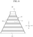
- FIG. 6 is a view seen when facing a cross-section along line VI-VI of FIG. 5 . It is noted that FIG. 6 illustrates a depth view seen when facing half the chute 300 cut along line VI-VI of FIG. 5 .
- the chute 300 may include a main body 310 and a plurality of internal pattern portions 320.
- the main body 310 may include an internal space IS through which the dry powder DP passes, an inlet 311 through which the dry powder DP discharged from the feeder 100 is supplied into the main body 310, and an outlet 312 through which the dry powder DP is discharged from the main body 310 into the trough 200.
- the inlet 311 and outlet 312 may be on opposite sides of the internal space IS of the main body 310 along the third direction Z.
- the internal space IS may be formed by expanding from the inlet 311 to the outlet 312 in the third direction Z that is a direction in which the main body 310 extends. That is, a width of the main body 310 may, e.g., gradually, increase in a direction oriented from the inlet 311 toward the outlet 312.
- the internal space IS may have a shape of an internal space of each of various known or any suitable chute, e.g., a shape of a cone or a pyramid.
- the inlet 311 may be disposed at an upper side of the internal space IS in the third direction Z, e.g., the inlet 311 may face the feeder 100.
- the inlet 311 may be a portion where the dry powder DP discharged from the feeder 100 is supplied.
- the outlet 312 may be disposed at a lower side of the internal space IS in the third direction Z, e.g., the outlet 312 may face the trough 200.
- the outlet 312 may be a portion where the dry powder DP is discharged from the inlet 311 through the internal space IS.
- the dry powder DP may be discharged from the outlet 312 to the trough 200.
- the outlet 312 may have a wider width than that of the inlet 311, e.g., in the first direction X and/or the second direction Y.
- a width of the outlet 312 may be greater than a width of the inlet 311.
- a width of the outlet 312 may include at least one of a width of the first direction X and a width of the second direction Y.
- the plurality of internal pattern portions 320 may be disposed in the internal space IS of the main body 310.
- the plurality of internal pattern portions 320 may be distributed and disposed in the internal space IS from the inlet 311 of the main body 310 to the outlet 312 of the main body 310.
- the plurality of internal pattern portions 320 may extend in the first direction X to be connected (e.g., directly connected) to an internal wall of the main body 310, e.g., each of the plurality of internal pattern portions 320 may extend continuously in the first direction X to be connected (e.g., directly connected) to opposite internal walls of the main body 310.
- the plurality of internal pattern portions 320 may be distributed and disposed, e.g., spaced apart from each other, in the second direction Y and the third direction Z in the internal space IS of the main body 310. For example, referring to FIG.
- the rows of internal pattern portions 320 may be offset relative to each other in the second direction Y, but a viewer with respect to FIG. 6 may still face three internal pattern portions 320 that are on line VI-VI of FIG. 5 and additional two internal pattern portions 320 that are offset from the line VI-VI of FIG. 5 along the second direction Y.
- each of the plurality of internal pattern portions 320 may have a triangular shape in the third direction Z, e.g., a triangular cross-section in a plane defined by the second and third directions Y and Z that is oriented to have an increasing width toward the outlet 312.
- each of the plurality of internal pattern portions 320 may have various shapes such as any suitable polygonal shape (e.g., a quadrangular shape, a pentagonal shape, a hexagonal shape, or the like), a circular shape, an oval shape, a linear shape, a curved shape, and the like.
- the plurality of internal pattern portions 320 may be distributed and disposed, e.g., spaced apart from each other, in the second direction Y and the third direction Z in the internal space IS of the main body 310, so that the dry powder DP supplied from the feeder 100 to the inlet 311 collides with the plurality of internal pattern portions 320 to be widely dispersed (e.g., via the offset and spaced apart triangular shapes) in the second direction Y while passing through the internal space IS in the third direction Z.
- FIG. 7 is a front view of a chute 300' of a dry powder feeding apparatus according to example embodiments.
- FIG. 8 is a cross-sectional view taken along line VIII-VIII of FIG. 7 . It is noted that FIG. 8 illustrates a depth view seen when facing half the chute 300' cut along line VIII-VIII of FIG. 7 .
- the dry powder feeding apparatus may include the feeder 100, the trough 200, and the chute 300' therebetween.
- Each of the plurality of internal pattern portions 320 of the chute 300' may include a mesh extending from the inlet 311 of the main body 310 toward an outer region of the outlet 312 of the main body 310.
- the mesh may extend from a central region of the inlet 311 to the outer region of the outlet 312 along the internal wall of the main body 310, and the mesh may extend in the first direction X, the second direction Y, the third direction Z, or another direction to be connected to the internal wall of the main body 310.
- the plurality of internal pattern portions 320 may have a predetermined thickness along a radial direction of the chute 300' and may extend along the internal wall of the main body 310 (i.e., the dashed rectangles in FIG. 7 ) to surround an empty space of the internal space IS.
- the mesh included in the internal pattern portion 320 may include a first sub-mesh 321, a second sub-mesh 322, and a third sub-mesh 323, e.g., stacked on top of each other in the third direction Z.
- sizes of the holes in the first through third sub-meshes may gradually increase from the inlet 311 toward the outlet 312 (e.g., FIG. 8 illustrates the mesh as it extends along the sidewall of the main body 310 and is spaced apart from the center of the chute 300').
- the first sub-mesh 321 may be adjacent to the inlet 311 of the main body 310, and may include a first through hole TH1.
- the second sub-mesh 322 may extend from the first sub-mesh 321 toward the outlet 312, and may include a second through hole TH2 that is larger than the first through hole TH1.
- the second sub-mesh 322 may connect the first sub-mesh 321 and the third sub-mesh 323.
- the third sub-mesh 323 may extend from the second sub-mesh 322 toward the outlet 312, and may include a third through hole TH3 that is larger than the second through hole TH2.
- each of the plurality of internal pattern portions 320 may include the mesh extending from the inlet 311 of the main body 310 to the outer region of the outlet 312 of the main body 310, so that the dry powder DP supplied from the feeder 100 to the inlet 311 sequentially passes through the first through hole TH1 of the first sub-mesh 321 of the mesh, the second through hole TH2 of the second sub-mesh 322 of the mesh, and the third through hole TH3 of the third sub-mesh 323 of the mesh to be widely dispersed in the second direction Y while passing through the internal space IS in the third direction Z.
- the dry powder DP discharged from the feeder 100 may collide with the plurality of internal pattern portions 320 to be widely dispersed in the second direction Y while passing through the chute 300 (or chute 300') in the third direction Z so that the dry powder DP discharged from the feeder 100 is moved to the trough 200.
- the dry powder DP passing along the bottom 210 of the trough 200 in the first direction X may be widely dispersed in the second direction Y on the bottom 210 by the plurality of bottom pattern portions 220 that vibrate due to vibration of the bottom 210 so that the dry powder DP passing along the bottom 210 of the trough 200 in the first direction X is moved to the dry electrode manufacturing apparatus.
- a dry powder feeding apparatus may include a feeder that discharges a fibrous dry powder, and a trough that moves the dry powder discharged from the feeder in one direction to supply the dry powder to a roll that performs calendering.
- the dry powder discharged from the feeder may not be widely dispersed on the trough due to low dispersibility and high cohesiveness of the fibrous dry powder, so that supply deviation may occur in the dry powder supplied to the roll performing calendering.
- example embodiments provide a dry powder feeding apparatus that manufactures a large-area dry electrode with improved uniformity because a supply deviation of a dry powder supplied to a roll performing calendering is minimized by widely dispersing a fibrous dry powder discharged from a feeder on a trough. That is, the dry powder feeding apparatus according to example embodiments includes internal pattern portions within the chute and bottom pattern portions inside the trough to increase dispersion distribution of the dry powder within the trough along a direction perpendicular to a length direction of the trough, thereby reducing supply deviation and increasing uniformity of the dry powder supplied to the calendering roll.
Landscapes
- Engineering & Computer Science (AREA)
- Mechanical Engineering (AREA)
- Manufacturing & Machinery (AREA)
- Chemical & Material Sciences (AREA)
- Chemical Kinetics & Catalysis (AREA)
- Electrochemistry (AREA)
- General Chemical & Material Sciences (AREA)
- Robotics (AREA)
- Battery Electrode And Active Subsutance (AREA)
Applications Claiming Priority (1)
| Application Number | Priority Date | Filing Date | Title |
|---|---|---|---|
| KR1020230112991A KR20250031468A (ko) | 2023-08-28 | 2023-08-28 | 건식 파우더 공급 장치 |
Publications (1)
| Publication Number | Publication Date |
|---|---|
| EP4516700A1 true EP4516700A1 (de) | 2025-03-05 |
Family
ID=91226802
Family Applications (1)
| Application Number | Title | Priority Date | Filing Date |
|---|---|---|---|
| EP24177179.9A Pending EP4516700A1 (de) | 2023-08-28 | 2024-05-21 | Trockenpulverzuführvorrichtung |
Country Status (4)
| Country | Link |
|---|---|
| US (1) | US20250074712A1 (de) |
| EP (1) | EP4516700A1 (de) |
| KR (1) | KR20250031468A (de) |
| CN (1) | CN119526671A (de) |
Citations (7)
| Publication number | Priority date | Publication date | Assignee | Title |
|---|---|---|---|---|
| JPS4835024B1 (de) * | 1968-10-04 | 1973-10-25 | ||
| JPS4947786B1 (de) * | 1970-02-05 | 1974-12-18 | ||
| JPS54183091U (de) * | 1978-06-16 | 1979-12-25 | ||
| JPH02133625U (de) * | 1989-04-12 | 1990-11-06 | ||
| JPH0647225U (ja) * | 1992-12-09 | 1994-06-28 | 株式会社エー・アンド・デイ | 粉粒体均し装置 |
| WO1998018571A1 (en) * | 1996-10-29 | 1998-05-07 | A.S.T. Advanced Screening Technologies Ltd. | A separator plate for the screening of particulate material |
| JP2000304900A (ja) * | 1999-04-22 | 2000-11-02 | Natl Food Res Inst | 電子線照射装置と粒状体殺菌方法 |
-
2023
- 2023-08-28 KR KR1020230112991A patent/KR20250031468A/ko active Pending
-
2024
- 2024-03-13 US US18/603,295 patent/US20250074712A1/en active Pending
- 2024-05-21 EP EP24177179.9A patent/EP4516700A1/de active Pending
- 2024-07-03 CN CN202410881755.0A patent/CN119526671A/zh active Pending
Patent Citations (7)
| Publication number | Priority date | Publication date | Assignee | Title |
|---|---|---|---|---|
| JPS4835024B1 (de) * | 1968-10-04 | 1973-10-25 | ||
| JPS4947786B1 (de) * | 1970-02-05 | 1974-12-18 | ||
| JPS54183091U (de) * | 1978-06-16 | 1979-12-25 | ||
| JPH02133625U (de) * | 1989-04-12 | 1990-11-06 | ||
| JPH0647225U (ja) * | 1992-12-09 | 1994-06-28 | 株式会社エー・アンド・デイ | 粉粒体均し装置 |
| WO1998018571A1 (en) * | 1996-10-29 | 1998-05-07 | A.S.T. Advanced Screening Technologies Ltd. | A separator plate for the screening of particulate material |
| JP2000304900A (ja) * | 1999-04-22 | 2000-11-02 | Natl Food Res Inst | 電子線照射装置と粒状体殺菌方法 |
Also Published As
| Publication number | Publication date |
|---|---|
| KR20250031468A (ko) | 2025-03-07 |
| CN119526671A (zh) | 2025-02-28 |
| US20250074712A1 (en) | 2025-03-06 |
Similar Documents
| Publication | Publication Date | Title |
|---|---|---|
| US11779953B2 (en) | Slot die for manufacturing rechargeable battery electrode | |
| EP1617495B1 (de) | Separator für eine speicherbatterie und speicherbatterie | |
| EP3657576A1 (de) | Elektrodenstruktur, verfahren zur herstellung davon und sekundärbatterie mit der elektrodenstruktur | |
| KR102731112B1 (ko) | 전극 구조체 및 그 제조방법과, 전극 구조체를 포함하는 이차 전지 | |
| EP3933964A1 (de) | Vorrichtung zur herstellung einer elektrode für sekundärbatterie, elektrode für sekundärbatterie und damit hergestellte sekundärbatterie | |
| EP4516700A1 (de) | Trockenpulverzuführvorrichtung | |
| EP4679513A1 (de) | Sekundärbatterie, batterieanordnung und elektronische vorrichtung | |
| US20220293963A1 (en) | Electrode structure, secondary battery including the same, and method of fabricating the electrode structure | |
| KR20170097515A (ko) | 이물질의 제거가 용이한 전극 시트 커팅 장치 | |
| US20240408694A1 (en) | Ultrasonic Welding Apparatus and Electrode Assembly Manufactured Thereby | |
| US10910663B2 (en) | Secondary battery | |
| KR101653215B1 (ko) | 슬롯 다이 코팅 장치 | |
| EP4272877A1 (de) | Abscheidungssystem | |
| EP4268975A1 (de) | Doppelschicht-abscheidung | |
| JP2025521993A (ja) | 電極組立体 | |
| KR20160002050A (ko) | 전극 조립체 | |
| US20250312817A1 (en) | Dry electrode manufacturing device and manufacturing method of the same | |
| US20250316676A1 (en) | Dry electrode manufacturing device and manufacturing method of the same | |
| US20260100403A1 (en) | Mandrel for winding electrode of secondary battery | |
| EP4566724A1 (de) | Schlitzdüse zur herstellung einer wiederaufladbaren batterieelektrode, wiederaufladbare batterieelektrode und herstellungsverfahren damit | |
| KR20260024279A (ko) | 다이 코터 및 이를 구비하는 코팅 장치 | |
| EP4670854A1 (de) | Schlitzdüsenbeschichter | |
| EP4238664A1 (de) | Vorrichtung zur entfernung von fremdstoffen | |
| US20240375143A1 (en) | Coating die and coating device | |
| KR20260057871A (ko) | 이차전지 전극기재 노칭장치 |
Legal Events
| Date | Code | Title | Description |
|---|---|---|---|
| PUAI | Public reference made under article 153(3) epc to a published international application that has entered the european phase |
Free format text: ORIGINAL CODE: 0009012 |
|
| STAA | Information on the status of an ep patent application or granted ep patent |
Free format text: STATUS: REQUEST FOR EXAMINATION WAS MADE |
|
| 17P | Request for examination filed |
Effective date: 20240521 |
|
| AK | Designated contracting states |
Kind code of ref document: A1 Designated state(s): AL AT BE BG CH CY CZ DE DK EE ES FI FR GB GR HR HU IE IS IT LI LT LU LV MC ME MK MT NL NO PL PT RO RS SE SI SK SM TR |