EP4516680A1 - Flugzeug mit mindestens einem hohlraum, der an einer aerodynamischen wand mit einer reduzierung des teildurchgangsquerschnitts aufweist - Google Patents
Flugzeug mit mindestens einem hohlraum, der an einer aerodynamischen wand mit einer reduzierung des teildurchgangsquerschnitts aufweist Download PDFInfo
- Publication number
- EP4516680A1 EP4516680A1 EP24196046.7A EP24196046A EP4516680A1 EP 4516680 A1 EP4516680 A1 EP 4516680A1 EP 24196046 A EP24196046 A EP 24196046A EP 4516680 A1 EP4516680 A1 EP 4516680A1
- Authority
- EP
- European Patent Office
- Prior art keywords
- side wall
- tubular side
- passage section
- cavity
- aircraft
- Prior art date
- Legal status (The legal status is an assumption and is not a legal conclusion. Google has not performed a legal analysis and makes no representation as to the accuracy of the status listed.)
- Pending
Links
Images

Classifications
-
- B—PERFORMING OPERATIONS; TRANSPORTING
- B64—AIRCRAFT; AVIATION; COSMONAUTICS
- B64C—AEROPLANES; HELICOPTERS
- B64C23/00—Influencing air flow over aircraft surfaces, not otherwise provided for
-
- B—PERFORMING OPERATIONS; TRANSPORTING
- B64—AIRCRAFT; AVIATION; COSMONAUTICS
- B64D—EQUIPMENT FOR FITTING IN OR TO AIRCRAFT; FLIGHT SUITS; PARACHUTES; ARRANGEMENT OR MOUNTING OF POWER PLANTS OR PROPULSION TRANSMISSIONS IN AIRCRAFT
- B64D33/00—Arrangement in aircraft of power plant parts or auxiliaries not otherwise provided for
- B64D33/02—Arrangement in aircraft of power plant parts or auxiliaries not otherwise provided for of combustion air intakes
-
- B—PERFORMING OPERATIONS; TRANSPORTING
- B64—AIRCRAFT; AVIATION; COSMONAUTICS
- B64D—EQUIPMENT FOR FITTING IN OR TO AIRCRAFT; FLIGHT SUITS; PARACHUTES; ARRANGEMENT OR MOUNTING OF POWER PLANTS OR PROPULSION TRANSMISSIONS IN AIRCRAFT
- B64D13/00—Arrangements or adaptations of air-treatment apparatus for aircraft crew or passengers, or freight space
-
- B—PERFORMING OPERATIONS; TRANSPORTING
- B64—AIRCRAFT; AVIATION; COSMONAUTICS
- B64C—AEROPLANES; HELICOPTERS
- B64C2230/00—Boundary layer controls
- B64C2230/08—Boundary layer controls by influencing fluid flow by means of surface cavities, i.e. net fluid flow is null
-
- B—PERFORMING OPERATIONS; TRANSPORTING
- B64—AIRCRAFT; AVIATION; COSMONAUTICS
- B64C—AEROPLANES; HELICOPTERS
- B64C2230/00—Boundary layer controls
- B64C2230/14—Boundary layer controls achieving noise reductions
-
- B—PERFORMING OPERATIONS; TRANSPORTING
- B64—AIRCRAFT; AVIATION; COSMONAUTICS
- B64D—EQUIPMENT FOR FITTING IN OR TO AIRCRAFT; FLIGHT SUITS; PARACHUTES; ARRANGEMENT OR MOUNTING OF POWER PLANTS OR PROPULSION TRANSMISSIONS IN AIRCRAFT
- B64D33/00—Arrangement in aircraft of power plant parts or auxiliaries not otherwise provided for
- B64D33/02—Arrangement in aircraft of power plant parts or auxiliaries not otherwise provided for of combustion air intakes
- B64D2033/0206—Arrangement in aircraft of power plant parts or auxiliaries not otherwise provided for of combustion air intakes comprising noise reduction means, e.g. acoustic liners
Definitions
- the present application relates to an aircraft comprising at least one cavity opening at an aerodynamic wall and provided with a partial passage section reduction.
- an aircraft 10 comprises a fuselage 12, wings 14 provided on either side of the fuselage 12 as well as propulsion assemblies 16 connected to the wings by masts 18.
- the aircraft 10 comprises at least one air intake device 20, visible in the figure 2 , which opens at an aerodynamic wall 22 in contact with an air flow 24 when the aircraft 10 is in flight.
- This air intake device 20 is configured to capture a portion of the air flow 24 and route it towards equipment of the aircraft.
- the aerodynamic wall 22 may be provided at the fuselage 12, a wing 14, a propulsion assembly 16 or a mast 18.
- the air intake device 20 comprises an intake duct 26, which extends between a first end 26.1 connected to the aerodynamic wall 22 and a second end 26.2, as well as a valve 28 connected to the second end 26.2 of the intake duct 26 and configured to occupy a passing state in which the valve 28 allows an air flow channeled by the intake duct 26 to pass through it and a closed state in which the valve 28 blocks the air flow in the intake duct 26.
- the first end 26.1 which opens at the level of the aerodynamic wall 22, is flared and forms a flush-type air inlet.
- the first end 26.1 of the intake duct 26 is positioned on a reference surface substantially parallel to the air flow 24, said reference surface being, outside the intake duct 26, merged with the outer face of the aerodynamic wall 22 in contact with the air flow 24.
- the air intake device 20 is optimized to reduce aircraft drag when the valve 28 is in the open state.
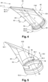
- the inlet duct 26 and the valve 28 in the closed state form a cavity 30, shown schematically in the figure 3 , which opens at the level of the aerodynamic wall 22.
- the air flow 24 which flows above the cavity 30 generates a noise of aerodynamic origin, in particular a whistling sound, due to the coupling between a return air flow 24.1 formed in the cavity 30 and a disturbed flow 24.2 appearing after the upstream edge 30.1 of the cavity 30.
- the present invention aims to remedy all or part of the drawbacks of the prior art.
- the invention relates to an aircraft comprising at least one aerodynamic wall against which an air flow flows in a flow direction when the aircraft is in flight and at least one cavity opening at the aerodynamic wall, said cavity being delimited by a tubular side wall which extends between first and second ends as well as a bottom distant from the aerodynamic wall and located at the second end of the tubular side wall, the first end of the tubular side wall being located at the aerodynamic wall, the cavity having a reference passage section and a depth, the tubular side wall being parallel to a reference direction and having a circumference.
- the cavity comprises at least one passage section reduction, distant from the bottom, which extends only over a part of the circumference of the tubular side wall.
- the reduction in passage section extends over half the circumference of the tubular side wall with a tolerance interval of +/- 20%, preferably +/- 5%.
- the passage section reduction is positioned in an upstream half-space delimited by a median plane perpendicular to the flow direction of the air flow.
- the passage section reduction is positioned in a transverse plane perpendicular to the reference direction.
- the transverse plane is located at a distance from the bottom of the order of 30% of the depth of the cavity with a tolerance interval of +/- 20%, preferably +/- 5%.
- the passage section reduction has a passage section of the order of 80% of the reference passage section with a tolerance interval of the order of +/- 10%, preferably +/- 5%.
- the tubular side wall is cylindrical and has a reference diameter.
- the reduction in passage section has a diameter of the order of 80% of the reference diameter with a tolerance interval of the order of +/- 10%, preferably +/- 5%.
- the passage section reduction comprises a rib, projecting relative to the tubular side wall, comprising a first edge which extends from the tubular side wall, oriented towards the first end of the tubular side wall, as well as a second edge which extends from the tubular side wall, oriented towards the bottom.
- the first edge forms an angle with the tubular side wall of between 20 and 60°, preferably between 30 and 40°.
- the second edge is substantially perpendicular to the tubular side wall.
- the rib is a hollow sausage attached to the tubular side wall.
- an aircraft comprises at least one aerodynamic wall 40 as well as at least one air intake device 42.
- the aerodynamic wall 40 has an outer face F40 against which an air flow 44 flows in a flow direction when the aircraft is in flight.
- the aerodynamic wall may be provided at the fuselage, a wing, a propulsion assembly or a mast of the aircraft.
- the air intake device 42 comprises an intake duct 46, which extends between a first end 46.1 connected to the aerodynamic wall 40 and a second end 46.2, as well as a valve 48 connected to the second end 46.2 of the intake duct 46 and configured to occupy a passing state in which the valve 48 allows an air flow channeled by the intake duct 46 to pass through it and a closed state in which the valve 48 blocks the air flow in the intake duct 46.
- the first end 46.1 opens at the aerodynamic wall 40 and has a shape that flares out toward the outer face F40 of the aerodynamic wall 40.
- the first end 46.1 of the intake duct 46 forms a flush-type air inlet.
- the first end 46.1 of the intake duct 46 is positioned on a reference surface S substantially parallel to the air flow 44, said reference surface S being, outside the intake duct 46, coincident with the outer face F40 of the aerodynamic wall 40 in contact with the air flow 44.
- the reference surface S and the outer face F40 can be either flat or curved.
- the intake duct 46 and the valve 48 in the closed state form a cavity 50 which opens at the level of the aerodynamic wall 40.
- This cavity 50 is delimited by a tubular side wall 52 (corresponding to the intake duct 46), which extends between first and second ends 52.1, 52.2, as well as by a bottom 54 (corresponding to the valve 48 and more particularly to the flap of the valve) distant from the aerodynamic wall 40 and located at the second end 52.2 of the tubular side wall 52, the first end 52.1 of the tubular side wall 52 (corresponding to the first end 46.1 of the intake duct 46) being located at the outer face F40 of the aerodynamic wall 40.
- the tubular side wall 52 is substantially parallel to a reference direction DD which may be perpendicular or inclined relative to the reference surface S. As an indication, the reference direction DD forms an angle of approximately 60° with the reference surface S.
- the tubular side wall 52 is cylindrical and has an axis of revolution A52 parallel to the reference direction.
- the bottom 54 is substantially perpendicular to the reference direction DD.
- the cavity 50 has a reference passage section Sr corresponding to the section of the tubular side wall 52.
- the reference passage section Sr is characterized by a diameter Dr, as illustrated in the figure. figure 6 .
- the cavity 50 has a depth P corresponding to the average distance between the reference surface S and the bottom 54.
- the depth P corresponds to a distance separating a first point of intersection between the axis of revolution A52 and the reference surface S as well as a second point of intersection between the axis of revolution A52 and the bottom 54.
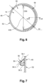
- the cavity 50 comprises at least one reduction in passage section 56 distant from the bottom 54 and partial.
- partial it is meant that the reduction in passage section 56 extends only over a portion of the circumference of the tubular side wall 52 and not over the entire circumference.
- the passage section reduction 56 is positioned in a transverse plane perpendicular to the reference direction DD.
- This transverse plane is located at a distance from bottom 54 of the order of 30% of depth P with a tolerance interval of +/- 20% and preferably +/- 5%.
- the passage section reduction 56 has a passage section of the order of 80% of the reference passage section Sr with a tolerance interval of the order of +/- 10%, preferably +/- 5%.
- the passage section reduction 56 has a diameter D56 of the order of 80% of the reference diameter Dr with a tolerance interval of the order of +/- 10%, preferably +/- 5%.
- the passage section reduction 56 extends over half the circumference of the tubular side wall 52 with a tolerance interval of +/- 20% and preferably +/- 5%.
- the passage section reduction 56 when the tubular side wall 52 is inclined, the passage section reduction 56 is positioned in an upstream half-space delimited by a median plane, passing through the axis of revolution A52, perpendicular to the direction of flow of the air flow 44.
- the term upstream refers to the direction of flow of the air flow 44, which flows from upstream to downstream.
- the passage section reduction 56 comprises a rib 58, projecting relative to the tubular side wall 52, comprising a first edge 58.1 which extends from the tubular side wall 52, oriented towards the first end 52.1 of the tubular side wall 52, as well as a second edge 58.1 which extends from the tubular side wall 52, oriented towards the bottom 54.
- the first edge 58.1 forms an angle A1 with the tubular side wall 52 of between 20 and 60°, preferably of between 30 and 40°.
- the second edge 58.2 is substantially perpendicular to the tubular side wall 52.
- the rib 58 has an intermediate zone 58.3 interposed between the first and second edges 58.1, 58.2 and connecting them. According to one configuration, this intermediate zone 58.3 may be curved.
- the rib 58 is a hollow bead attached to the tubular side wall 52.
- the rib 58 is made of plastic and fixed to the tubular side wall 52 by gluing or any other means.
- Rib 58 could be solid. The fact that the sausage is hollow allows the mass to be reduced.
- passage section reduction 56 is distant from the bottom 54 and partial (not continuous over the entire circumference of the tubular side wall 52) makes it possible to obtain a reduction in noise of aerodynamic origin.
Landscapes
- Engineering & Computer Science (AREA)
- Aviation & Aerospace Engineering (AREA)
- Chemical & Material Sciences (AREA)
- Combustion & Propulsion (AREA)
- Health & Medical Sciences (AREA)
- General Health & Medical Sciences (AREA)
- Pulmonology (AREA)
- Structures Of Non-Positive Displacement Pumps (AREA)
- Check Valves (AREA)
Applications Claiming Priority (1)
| Application Number | Priority Date | Filing Date | Title |
|---|---|---|---|
| FR2309021 | 2023-08-28 |
Publications (1)
| Publication Number | Publication Date |
|---|---|
| EP4516680A1 true EP4516680A1 (de) | 2025-03-05 |
Family
ID=88689517
Family Applications (1)
| Application Number | Title | Priority Date | Filing Date |
|---|---|---|---|
| EP24196046.7A Pending EP4516680A1 (de) | 2023-08-28 | 2024-08-23 | Flugzeug mit mindestens einem hohlraum, der an einer aerodynamischen wand mit einer reduzierung des teildurchgangsquerschnitts aufweist |
Country Status (3)
| Country | Link |
|---|---|
| US (1) | US20250074580A1 (de) |
| EP (1) | EP4516680A1 (de) |
| CN (1) | CN119527560A (de) |
Citations (4)
| Publication number | Priority date | Publication date | Assignee | Title |
|---|---|---|---|---|
| EP0926064B1 (de) * | 1997-12-19 | 2003-05-07 | The Boeing Company | Strömungskontrollevorrichtung zur Beseitigung von Hohlraumresonanzen |
| EP1251069B1 (de) * | 2001-04-20 | 2004-09-29 | Liebherr-Aerospace Lindenberg GmbH | Stauluftkanal für eine Flugzeugklimaanlage |
| EP2464568B1 (de) * | 2009-08-11 | 2015-07-15 | Airbus Operations Limited | Abgasumleiter |
| EP1828571B1 (de) * | 2004-12-20 | 2016-04-20 | Airbus Operations (Sas) | Lufteinlassanordnung einer belüftung |
-
2024
- 2024-08-22 CN CN202411160617.XA patent/CN119527560A/zh active Pending
- 2024-08-23 EP EP24196046.7A patent/EP4516680A1/de active Pending
- 2024-08-26 US US18/814,698 patent/US20250074580A1/en active Pending
Patent Citations (4)
| Publication number | Priority date | Publication date | Assignee | Title |
|---|---|---|---|---|
| EP0926064B1 (de) * | 1997-12-19 | 2003-05-07 | The Boeing Company | Strömungskontrollevorrichtung zur Beseitigung von Hohlraumresonanzen |
| EP1251069B1 (de) * | 2001-04-20 | 2004-09-29 | Liebherr-Aerospace Lindenberg GmbH | Stauluftkanal für eine Flugzeugklimaanlage |
| EP1828571B1 (de) * | 2004-12-20 | 2016-04-20 | Airbus Operations (Sas) | Lufteinlassanordnung einer belüftung |
| EP2464568B1 (de) * | 2009-08-11 | 2015-07-15 | Airbus Operations Limited | Abgasumleiter |
Also Published As
| Publication number | Publication date |
|---|---|
| CN119527560A (zh) | 2025-02-28 |
| US20250074580A1 (en) | 2025-03-06 |
Similar Documents
| Publication | Publication Date | Title |
|---|---|---|
| EP3380399B1 (de) | Von einer turbomaschine mit schallwand angetriebenes flugzeug | |
| CA2694996C (fr) | Chevron anti-bruit pour tuyere, tuyere et turbomoteur pourvus d'un tel chevron | |
| EP1270101B1 (de) | Dünne und verteilte rohrförmige Struktur und Herstellungsverfahren | |
| EP2554822B1 (de) | Speziell angepasste Verbindungsvorrichtung zur Sicherstellung der Verbindung zwischen einem Lufteinlass und der Motorisierung einer Luftfahrzeuggondel | |
| FR2958624A1 (fr) | Mat d'accrochage pour turbomoteur d'aeronef, comprenant un volet arriere mobile en incidence | |
| FR2929334A1 (fr) | Dispositif de reduction du bruit genere par reacteur d'aeronef a conduits de fluide coudes | |
| FR3013393A1 (de) | ||
| CA2872207A1 (fr) | Dispositif d'ejection d'air comprenant un profil aerodynamique muni d'une languette flexible d'obturation de fente | |
| FR3044295A1 (fr) | Dispositif formant un bord de fuite d'un profil aerodynamique et comportant un systeme de soufflage | |
| FR2974563A1 (fr) | Profil aerodynamique reduisant le deficit de vitesse dans son sillage | |
| FR3055612A1 (fr) | Structure compartimentee pour le traitement acoustique et le degivrage d'une nacelle d'aeronef et nacelle d'aeronef incorporant ladite structure | |
| EP3534360B1 (de) | Schalldämmende beschichtung, die eine wabenstruktur mit gekrümmten zellen umfasst, die auf der einen und der anderen seite aus derselben innenwand gebildet werden | |
| EP4516680A1 (de) | Flugzeug mit mindestens einem hohlraum, der an einer aerodynamischen wand mit einer reduzierung des teildurchgangsquerschnitts aufweist | |
| CA2576700C (fr) | Entree d'air de turboreacteur a double flux | |
| WO2010061071A2 (fr) | Nacelle integree sur aile volante | |
| EP4501793A1 (de) | Flugzeuglufteinlass mit einer aussenwand und vorder- und hinterrahmen, die durch mindestens ein separates verbindungselement der aussenwand verbunden sind | |
| FR2993862A1 (fr) | Entree d'air pour moteur d'helicoptere a circulation de contournement augmentee | |
| FR2913401A1 (fr) | Mat pour nacelle d'aeronef incorporant des moyens pour limiter l'apparition de vibrations, en particulier a certains regimes de vol, a fort nombre de mach et faible portance | |
| EP4375192A1 (de) | Flugzeug mit mindestens einer zur begrenzung des auftretens von aerodynamischem geräusch konfigurierten lufteinlassvorrichtung | |
| EP4173961B1 (de) | Flugzeuggondel mit einer verbindung zwischen durchgängen mit nach innen gerichteten flanschen und flugzeug mit mindestens einer solchen gondel | |
| FR3044292A1 (fr) | Profil aerodynamique d'aeronef a bord d'attaque ouvert, mat et aeronef comportant un tel profil aerodynamique | |
| FR3117548A1 (fr) | Dispositif d’entrainement d’un flux d’air principal pour une turbomachine d’aeronef | |
| FR2866931A1 (fr) | Helice monica | |
| EP4341540A1 (de) | Vorrichtung zur führung eines hauptluftstroms für ein flugzeugturbinentriebwerk | |
| FR3068080B1 (fr) | Nacelle d'aeronef comportant un volet inverseur et un joint |
Legal Events
| Date | Code | Title | Description |
|---|---|---|---|
| PUAI | Public reference made under article 153(3) epc to a published international application that has entered the european phase |
Free format text: ORIGINAL CODE: 0009012 |
|
| STAA | Information on the status of an ep patent application or granted ep patent |
Free format text: STATUS: THE APPLICATION HAS BEEN PUBLISHED |
|
| AK | Designated contracting states |
Kind code of ref document: A1 Designated state(s): AL AT BE BG CH CY CZ DE DK EE ES FI FR GB GR HR HU IE IS IT LI LT LU LV MC ME MK MT NL NO PL PT RO RS SE SI SK SM TR |
|
| STAA | Information on the status of an ep patent application or granted ep patent |
Free format text: STATUS: REQUEST FOR EXAMINATION WAS MADE |
|
| 17P | Request for examination filed |
Effective date: 20250820 |