EP4516677A1 - Ensemble pour un aéronef comportant une aile et un mât réacteur pour coupler un système de propulsion à ladite aile - Google Patents
Ensemble pour un aéronef comportant une aile et un mât réacteur pour coupler un système de propulsion à ladite aile Download PDFInfo
- Publication number
- EP4516677A1 EP4516677A1 EP24196886.6A EP24196886A EP4516677A1 EP 4516677 A1 EP4516677 A1 EP 4516677A1 EP 24196886 A EP24196886 A EP 24196886A EP 4516677 A1 EP4516677 A1 EP 4516677A1
- Authority
- EP
- European Patent Office
- Prior art keywords
- starboard
- port
- fixed
- fitting
- assembly
- Prior art date
- Legal status (The legal status is an assumption and is not a legal conclusion. Google has not performed a legal analysis and makes no representation as to the accuracy of the status listed.)
- Pending
Links
Images
Classifications
-
- B—PERFORMING OPERATIONS; TRANSPORTING
- B64—AIRCRAFT; AVIATION; COSMONAUTICS
- B64D—EQUIPMENT FOR FITTING IN OR TO AIRCRAFT; FLIGHT SUITS; PARACHUTES; ARRANGEMENT OR MOUNTING OF POWER PLANTS OR PROPULSION TRANSMISSIONS IN AIRCRAFT
- B64D27/00—Arrangement or mounting of power plants in aircraft; Aircraft characterised by the type or position of power plants
- B64D27/40—Arrangements for mounting power plants in aircraft
-
- B—PERFORMING OPERATIONS; TRANSPORTING
- B64—AIRCRAFT; AVIATION; COSMONAUTICS
- B64D—EQUIPMENT FOR FITTING IN OR TO AIRCRAFT; FLIGHT SUITS; PARACHUTES; ARRANGEMENT OR MOUNTING OF POWER PLANTS OR PROPULSION TRANSMISSIONS IN AIRCRAFT
- B64D27/00—Arrangement or mounting of power plants in aircraft; Aircraft characterised by the type or position of power plants
- B64D27/40—Arrangements for mounting power plants in aircraft
- B64D27/404—Suspension arrangements specially adapted for supporting vertical loads
-
- B—PERFORMING OPERATIONS; TRANSPORTING
- B64—AIRCRAFT; AVIATION; COSMONAUTICS
- B64D—EQUIPMENT FOR FITTING IN OR TO AIRCRAFT; FLIGHT SUITS; PARACHUTES; ARRANGEMENT OR MOUNTING OF POWER PLANTS OR PROPULSION TRANSMISSIONS IN AIRCRAFT
- B64D27/00—Arrangement or mounting of power plants in aircraft; Aircraft characterised by the type or position of power plants
- B64D27/02—Aircraft characterised by the type or position of power plants
- B64D27/10—Aircraft characterised by the type or position of power plants of gas-turbine type
- B64D27/12—Aircraft characterised by the type or position of power plants of gas-turbine type within, or attached to, wings
-
- B—PERFORMING OPERATIONS; TRANSPORTING
- B64—AIRCRAFT; AVIATION; COSMONAUTICS
- B64D—EQUIPMENT FOR FITTING IN OR TO AIRCRAFT; FLIGHT SUITS; PARACHUTES; ARRANGEMENT OR MOUNTING OF POWER PLANTS OR PROPULSION TRANSMISSIONS IN AIRCRAFT
- B64D27/00—Arrangement or mounting of power plants in aircraft; Aircraft characterised by the type or position of power plants
- B64D27/02—Aircraft characterised by the type or position of power plants
- B64D27/16—Aircraft characterised by the type or position of power plants of jet type
- B64D27/18—Aircraft characterised by the type or position of power plants of jet type within, or attached to, wings
-
- B—PERFORMING OPERATIONS; TRANSPORTING
- B64—AIRCRAFT; AVIATION; COSMONAUTICS
- B64D—EQUIPMENT FOR FITTING IN OR TO AIRCRAFT; FLIGHT SUITS; PARACHUTES; ARRANGEMENT OR MOUNTING OF POWER PLANTS OR PROPULSION TRANSMISSIONS IN AIRCRAFT
- B64D27/00—Arrangement or mounting of power plants in aircraft; Aircraft characterised by the type or position of power plants
- B64D27/40—Arrangements for mounting power plants in aircraft
- B64D27/402—Arrangements for mounting power plants in aircraft comprising box like supporting frames, e.g. pylons or arrangements for embracing the power plant
Definitions
- the present invention relates to an assembly for an aircraft comprising a wing and a power plant for coupling a propulsion system to the wing, as well as to an aircraft comprising a propulsion system and such an assembly for coupling the propulsion system to the wing.
- a propulsion system typically includes, for example, a turbojet engine that is attached to a wing of the aircraft using a jet engine pylon.
- the jet engine pylon is typically made up of a primary structure formed by a box consisting of an upper spar, a lower spar, and two side panels connecting the two spars, and internal ribs distributed along the box.
- the turbojet engine is fixed under the engine pylon by means of engine mounts which conventionally comprise, at the front, a front engine mount, at the rear, a rear engine mount, and between the front and rear engine mounts, a thrust force recovery assembly comprising recovery rods fixed between the turbojet engine and the primary structure of the pylon, to absorb the thrust forces generated by the turbojet engine.
- engine mounts which conventionally comprise, at the front, a front engine mount, at the rear, a rear engine mount, and between the front and rear engine mounts, a thrust force recovery assembly comprising recovery rods fixed between the turbojet engine and the primary structure of the pylon, to absorb the thrust forces generated by the turbojet engine.
- the engine pylon is further secured to the wing structure by means of fittings through which the forces from the turbojet are transferred to the wing structure.
- An object of the present invention is to provide an assembly for an aircraft comprising a wing and a reactor mast for coupling a propulsion system to the wing and which comprises means of attachment to the wing which ensure an improved transfer of forces to the structure of the wing while making it possible to guarantee the transmission of these forces in the event of breakage of a fixing element.
- a rear portion of said primary structure comprises a first fixing yoke extending at the rear and at the level of the vertical median plane, said first fixing yoke being fixed to said first fitting by a seventh connection having at least one degree of freedom in rotation about an axis extending generally parallel to the median plane.
- the rear part also includes a starboard fixing clevis and a port fixing clevis extending on either side and aft of said rear part.
- each shackle comprises two plates joined together and fixed against each other.
- said starboard and port fittings have a generally T-shaped section with a horizontal part fixed to the lower part of said front spar and a vertical part in which the associated pivot connections are made.
- each starboard and port fitting is made up of two elements having a generally ⁇ -shaped section and being integral with one another.
- said first fixing yoke comprises two sub-yokes joined together and fixed against each other.
- the seventh connection between said first fixing yoke and said first fitting comprises a main axis and a secondary axis extending coaxially and inside said main axis.
- said rear part comprises a first port outgrowth and a first starboard outgrowth extending vertically in a plane generally perpendicular to the vertical median plane, said first outgrowths being arranged on either side of said primary structure.
- the assembly comprises a first connecting rod, a first end of which is fixed to said first outgrowth by an eighth pivot connection.
- the assembly comprises a second connecting rod, a first end of which is fixed to said first starboard outgrowth by a ninth pivot connection.
- Said port and starboard fittings respectively comprise a second port protrusion and a second starboard protrusion extending vertically in a plane generally perpendicular to the vertical median plane.
- Said second protrusions extend in the lower part of the fittings, the second starboard protrusion being fixed to a second end of said first connecting rod by a tenth pivot connection and said second port protrusion being fixed to a second end of said second connecting rod by an eleventh pivot connection.
- said eighth and ninth pivot links have an adjusted connection axis and at least one of said tenth and eleventh pivot links has play.
- the invention also provides an aircraft comprising a propulsion system and an assembly as described above, where the propulsion system is attached to the engine pylon.
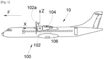
- FIG. 1 shows an aircraft 10 which comprises a propulsion system 102, for example of the turbojet or turboprop type.
- the propulsion system 102 is linked to a wing 104 of the aircraft 10 by means of a reactor mast 106.
- the wing 104 and the reactor mast 106 form an assembly 100 according to the invention and the propulsion system 102 is fixed to the reactor mast 106 by any suitable fixing means known to those skilled in the art such as those disclosed in the document US-A-2016/0221682 .
- X the longitudinal direction of the propulsion system which is horizontal when the aircraft is on the ground
- Y the transverse direction which is horizontal when the aircraft is on the ground
- Z the vertical direction which is vertical when the aircraft is on the ground
- the reactor mast 106 and the propulsion system 102 have a vertical median plane XZ and the propulsion system 102 is here a turboprop with a propeller 102a, but it could be of the double-flow turbojet type with a nacelle.
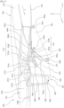
- the reactor mast 106 comprises a rigid structure forming a box and also called primary structure 202.
- the primary structure 202 illustrated here in section along a plane parallel to the ZY plane, is conventionally formed of an upper spar 204, a lower spar 206 and two starboard and port side panels connecting the two spars 204 and 206.
- the shape of the primary structure 202 is in this example configured so that the reactor mast 106 has a substantially rectangular rear portion 203, located at the rear end of the reactor mast 106 in the direction of advancement F.
- the structure of the wing 104 comprises a front spar 210, an extrados panel 214 and a lower surface panel 216 which are both fixed to the front spar 210 and extend generally in horizontal planes XY.
- its structure comprises other elements (not illustrated) such as ribs which are distributed between the extrados panel 214 and the lower surface panel 216.
- the front spar 210 here takes the form of a profile in the shape of an inverted Z step on the Figs. 2 And 3 , with an upper wing 210a (also called a top portion) and a lower wing 210b (also called a bottom portion) that are generally horizontal and a central portion 210c generally perpendicular to the median plane and extending generally vertically parallel to the YZ plane.
- the extrados panel 214 is attached above the upper wing 210a of the spar 210 and the intrados panel 216 is attached below the lower wing 210b of the spar 210.
- the attachment of the front spar 210 to the panels 214 and 216 is achieved by any suitable means such as welds, bolts, etc.
- the extrados panel 214 is thus fixed in the upper part of the front spar 210 and the intrados panel 216 is fixed in the lower part of the front spar 210.
- the central part 210c is at the level of the leading edge of the wing 104.
- the front spar 210 carries a first fitting 211a, called the central fitting, fixed at the level of the vertical median plane XZ and more particularly here at the central part 210c of the front spar 210.
- the intrados panel 216 carries a starboard fitting 212 and a port fitting 213 which are fixed to the external face of the intrados panel 216.
- the starboard 212 and port 213 fittings are fixed at the level, that is to say generally in vertical alignment, of the lower part 210b of the front spar 210.
- the assembly 100 comprises a first starboard shackle 282 fixed to the starboard fitting 212 by a first 292a and a second 292c pivot links whose axis of rotation is generally horizontal. More precisely, the axes of the links 292a and 292c extend generally perpendicular to the median plane XZ.
- the assembly also includes a first port shackle 283 fixed to the port fitting 213 by a fourth 293a and a fifth 293c pivot links around an axis whose axis of rotation is generally horizontal. More precisely, the axes of the links 293a and 293c extend generally perpendicular to the median plane (XZ).
- the rear portion 203 of the primary structure 202 comprises a first fixing yoke 211b which extends to the rear and at the level of the vertical median plane XZ. More precisely, the first fixing yoke 211b extends at the top of the rear portion 203 and is located opposite the first fitting 211a.
- the first fixing yoke 211b is fixed to the first fitting 211a by a seventh connection 211c having at least one degree of freedom in rotation about a vertical axis extending parallel to the vertical axis Z.
- the seventh connection 211c may be in the form of a pivot connection or a pivot-sliding connection.
- the first fitting 211a takes the form of a female yoke and the first fixing yoke 211b takes the form of a male yoke inserted into the female yoke.
- This attachment point between the engine mast 106 and the wing 104 makes it possible to absorb the axial forces along the X axis and the lateral forces along the Y axis. This attachment point also makes it possible to absorb the moment around the Y axis.
- the rear portion 203 also includes a starboard fixing yoke 272 and a port fixing yoke 273 which extend to the rear of the rear portion 203. More particularly here, the starboard fixing yoke 272 and port fixing yoke 273 extend in the lower part and on either side of said rear portion 203.
- the starboard attachment yoke 272 is attached by a third pivot link 292e to the starboard shackle 282 about a generally horizontal axis and the port attachment yoke 273 is attached by a sixth pivot link 293e to the port shackle 283 about a horizontal axis.
- the axes of the third and sixth pivot links 292e and 293e extend generally perpendicular to the median plane XZ, i.e. generally parallel to the transverse axis Y.
- the axes of the links 292e and 293e may further extend generally coaxially.
- the two attachment points of the starboard 272 and port 273 attachment clevises located on either side of the lower spar 206 of the primary structure 202 are connected to the starboard 212 and port 213 fittings secured to the wing 104 by two first starboard 282 and port 283 shackles having three attachment points (namely the associated pivot connections described above).
- these different attachment points of the engine pylon 106 to the wing 104 make it possible to ensure the transfer of vertical forces (along the Z axis) and axial forces (along the X axis).
- These fixing points also make it possible to take up the moments around the X and Z axes.
- This particular implementation also makes it possible to precisely determine the paths taken by the forces through the engine mast 106 to the wing 104.
- the first starboard 282 and port 283 shackles, the starboard 282 and port 283 clevises and the starboard 212 and port 213 fittings each have a bore into which a pin is threaded so as to form the pivot connections 292a, 292c, 292e and 293a, 293c, 293e.
- the first starboard shackle 282 and the first port shackle 283 have a generally triangular shape.
- the first 292a and second 292c pivot links are disposed respectively in a first 292b and a second 292d corner.
- top of the first starboard shackle and the third pivot link 292e is disposed in a third bottom corner 292f of the first starboard shackle 282.
- the fourth 293a and fifth 293c pivot links are disposed respectively in a fourth 293b and a fifth 293d top corners of the first port shackle 213 and the sixth pivot link 293e is disposed in a sixth bottom corner 293f of the first port shackle 283.
- triangular shackles makes it possible in particular to make the assembly 100 compatible with the use of an aerodynamically shaped fairing at least partially covering the reactor mast 106.
- the assembly 100 comprises a second starboard shackle 282' which extends generally parallel to the first starboard shackle 282 and which is fixed to the starboard fitting 212 by the first 292a and second 292c connections and to the starboard fixing clevis by the third connection 292e.
- the assembly 100 comprises a second port shackle 283' which extends generally parallel to the first port shackle 283 and which is fixed to the port fitting 213 by the fourth 293a and fifth 293c connections and to the port fixing clevis 273 by said sixth connection 293e.
- first 282 and second 282' starboard shackles grip the starboard fitting 212 and the starboard fixing clevis 272 while the first 283 and second 283' port shackles grip the port fitting 213 and the port fixing clevis 273.
- each starboard 212 and port 213 fitting is connected respectively to the starboard fixing clevis 272 and to the port fixing clevis 273 by two shackles, respectively 282, 282' and 283, 283'.
- Doubling the starboard and port shackles makes it possible to multiply the paths taken by the forces passing from the propulsion system 102 to the wing 104. This also makes it possible to ensure continuity of the transfers of forces in the event of breakage of one of the shackles or of a point of attachment of these shackles at the level of the engine pylon 106 or the wing 104.
- first and second starboard shackles 282 and 282' are generally identical. The same is true for the first and second port shackles 283 and 283'. However, it is conceivable to provide different shapes for the first and second shackles.
- each shackle 282, 282', 283, 283' comprises two plates 282a, 282a', 282b, 282b', 283a, 283a', 283b, 283b' joined and fixed against each other.
- the first starboard shackle 282 comprises two plates 282a and 282b
- the second starboard shackle 282' comprises two plates 282a' and 282b'
- the first shackle port shackle 283 has two plates 283a and 283b
- the second port shackle 283' has two plates 283a' and 283b'.
- the plates of each shackle are identical.
- each shackle makes it possible to multiply the paths taken by the forces passing from the propulsion system 102 to the wing 104 and to ensure continuity of the transfers of forces in the event of breakage of one of the plates of each shackle or of a fixing point of these plates.
- the starboard 212 and port 213 fittings have a generally T-shaped section with a horizontal part fixed to the lower part 210b of the front spar 210 and a vertical part in which the associated pivot connections are made. More precisely, the vertical part of the starboard fitting 212 has two bores in which pins are threaded to respectively form the first 292a and the second 292b connections.
- the vertical part of the port fitting 213 has two bores into which pins are threaded to respectively form the fourth 293a and the fifth 293b connections.
- each starboard 212 and port 213 fitting is made up of two elements, respectively 212a, 212b and 213a, 213b, having a generally ⁇ -shaped section.
- the two elements of each fitting are secured to each other. More precisely, the two elements of each fitting are secured to each other by the vertical parts of the ⁇ which together form the vertical part of the T of the fitting, while the horizontal parts of these ⁇ -shaped elements are arranged opposite each other and together form the horizontal part of the T of the fitting.
- each fitting makes it possible to multiply the paths taken by the forces passing from the propulsion system 102 to the wing 104 and to ensure continuity of the transfers of forces in the event of breakage of one of the elements of each fitting.
- the first fixing yoke 211b comprises two sub-yokes 2111 and 2113 joined and fixed against each other.
- the two sub-yokes 2111 and 2113 are identical.
- the implementation of two sub-yokes 2111 and 2113 fixed to each other to form the first fixing yoke 221b makes it possible to multiply the paths taken by the forces passing from the propulsion system 102 to the wing 104 and to ensure continuity of the transfers of forces in the event of rupture of one of the sub-yokes of the first fixing yoke 211b.
- the seventh connection 211c between the first fixing yoke 211b and the first fitting 211a comprises a main axis (not shown) and a secondary axis (not shown) extending coaxially and inside the main axis.
- the main axis and the secondary axis extend parallel to the vertical axis Z.
- first fitting 211a and the first fixing yoke 211b each comprise a bore in which the main axis is threaded to form the seventh pivot connection 211c.
- the secondary axis is threaded into the main axis so as to ensure continuity of force transfers in the event of breakage of the main axis.
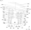
- the assembly 100 further comprises a set of two connecting rods 275a, 275b making it possible to react to the forces coming from the propulsion system 102 and which could generate an oscillatory movement on the reactor mast 106.
- the rear part 203 of the primary structure 202 comprises a first port outgrowth 274a and a first starboard outgrowth 274b.
- each first outgrowth 274a, 274b has an ear shape and extends vertically and perpendicularly to the side walls 208 of the primary structure 202, that is to say in a plane perpendicular to the vertical median plane XZ. More precisely, the first outgrowths 274a and 274b here extend generally to half the height of their respective side wall 208.
- the port 213 and starboard 212 fittings respectively carry a second port protrusion 274c and a second starboard protrusion 274d.
- each second protrusion 274c, 274d also has an ear shape and extends vertically in a plane perpendicular to the vertical median plane XZ.
- the second protrusions 274c, 274d extend on the vertical part of the T of each fitting.
- first protrusions 274a and 274b face each other.
- second protrusions 274c and 274d also face each other.
- the set of connecting rods 275a, 275b crosswise connects the fittings 212 and 213 to the rear part 203 of the primary structure 202. More precisely, a first connecting rod 275a connects the first port protrusion 274a to the second starboard protrusion 274d while the second connecting rod 275b connects the first starboard protrusion 274b to the second port protrusion 274c.
- the first 275a and second 275b connecting rods are therefore crossed and extend substantially in two parallel planes perpendicular to the vertical median plane XZ. The two parallel planes are slightly spaced to facilitate the crossing of the first 275a and second 275b connecting rods.
- first connecting rod 275a The ends of the first connecting rod 275a are secured to the first port outgrowth 274a and to the second starboard outgrowth 274d respectively by an eighth 284a and a ninth 284b pivot connections.
- the ends of the second connecting rod 275b are secured to the first starboard outgrowth 274b and to the second port outgrowth 274c respectively by a tenth 284c and an eleventh 284d pivot connections.
- the first connecting rod 275a is said to be “engaged” while the second connecting rod 275b is said to be “on standby”.
- the connecting axes of the eighth 284a and ninth 284b pivot connections are adjusted and therefore react to the forces under stress, so that the first connecting rod 275a represents the so-called "main" force path for the transmission of forces having a component substantially oriented in the transverse direction Y.
- At least one of the tenth 284c and eleventh 284d pivot connections has a clearance which allows, in the event of breakage of the first connecting rod 275a, to engage the second connecting rod 275b so that it is the second connecting rod 275b which reacts to the forces.
- the second connecting rod 275b thus represents the so-called “secondary” force path.
- the twelfth 284c and thirteenth 284d pivot connections each have a connecting pin carried respectively by the first starboard protrusion 274b and by the second port protrusion 274c.
- At least one of the bores provided at the ends of the second connecting rod 275b and cooperating with these connecting pins has, for example, an oblong shape such that the second connecting rod 275b is mounted with play at at least one of the tenth 284c and eleventh 284d pivot connections.
Landscapes
- Engineering & Computer Science (AREA)
- Aviation & Aerospace Engineering (AREA)
- Mutual Connection Of Rods And Tubes (AREA)
- Jib Cranes (AREA)
- Transmission Devices (AREA)
Abstract
Description
- La présente invention concerne un ensemble pour un aéronef qui comporte une aile et un mât réacteur pour coupler un système de propulsion à l'aile, ainsi qu'un aéronef comportant un système de propulsion et un tel ensemble pour coupler le système de propulsion à l'aile.
- Habituellement, pour un aéronef, un ensemble de propulsion comporte par exemple un turboréacteur qui est fixé à une aile de l'aéronef à l'aide d'un mât réacteur. Le mât réacteur est généralement constitué d'une structure primaire formée d'un caisson constitué d'un longeron supérieur, d'un longeron inférieur et de deux panneaux latéraux reliant les deux longerons et de nervures internes réparties le long du caisson.
- Le turboréacteur est fixé sous le mât réacteur au moyen d'attaches moteur qui comprennent classiquement, à l'avant, une attache moteur avant, à l'arrière, une attache moteur arrière, et entre les attaches moteur avant et arrière, un assemblage de reprise d'effort de poussée comprenant des bielles de reprise fixées entre le turboréacteur et la structure primaire du mât, pour absorber les forces de poussée générées par le turboréacteur.
- Le mât réacteur est en outre fixé à la structure de l'aile à l'aide de ferrures à travers lesquelles les efforts provenant du turboréacteur transitent vers la structure de l'aile. Bien que les installations actuelles donnent satisfaction, il est nécessaire de fournir une implantation où le transfert d'efforts est amélioré et où la sécurité est améliorée, par exemple en cas de rupture d'un élément constitutif de la fixation.
- Un objet de la présente invention est de proposer un ensemble pour un aéronef comportant une aile et un mât réacteur pour coupler un système de propulsion à l'aile et qui comporte des moyens de fixation à l'aile qui assurent un transfert amélioré des efforts vers la structure de l'aile tout en permettant de garantir la transmission de ces efforts en cas de rupture d'un élément de fixation.
- À cet effet, est proposé un ensemble pour le montage sur un aéronef d'un système de propulsion présentant un plan médian vertical, ledit ensemble comportant :
- une aile avec un longeron avant et un panneau d'intrados fixé à une partie basse dudit longeron avant, où le longeron avant porte une première ferrure au niveau du plan médian vertical et où ledit panneau d'intrados porte une ferrure tribord et une ferrure bâbord,
- un mât réacteur comportant une structure primaire,
- une première manille tribord fixée à ladite ferrure tribord par une première et une deuxième liaisons pivot autour d'un axe s'étendant globalement perpendiculairement au plan médian,
- une première manille bâbord fixée à ladite ferrure bâbord par une quatrième et une cinquième liaisons pivot autour d'un axe s'étendant globalement perpendiculairement au plan médian.
- Une partie arrière de ladite structure primaire comporte une première chape de fixation s'étendant à l'arrière et au niveau du plan médian vertical, ladite première chape de fixation étant fixée à ladite première ferrure par une septième liaison présentant au moins un degré de liberté en rotation autour d'un axe s'étendant globalement parallèlement au plan médian.
- La partie arrière comporte aussi une chape de fixation tribord et une chape de fixation bâbord s'étendant de part et d'autre et à l'arrière de ladite partie arrière.
- Ladite chape de fixation tribord est fixée par une troisième liaison pivot à ladite première manille tribord autour d'un axe s'étendant globalement perpendiculairement au plan médian et ladite chape de fixation bâbord est fixée par une sixième liaison pivot à ladite première manille bâbord autour d'un axe s'étendant globalement perpendiculairement au plan médian. Avantageusement, l'ensemble comporte en outre :
- une deuxième manille tribord s'étendant globalement parallèlement à ladite première manille tribord, ladite deuxième manille tribord étant fixée à ladite ferrure tribord par lesdites première et deuxième liaisons et à ladite chape tribord par ladite troisième liaison,
- une deuxième manille bâbord s'étendant globalement parallèlement à ladite première manille bâbord, ladite deuxième manille bâbord étant fixée à ladite ferrure bâbord par lesdites quatrième et cinquième liaisons et à ladite chape de fixation bâbord par ladite sixième liaison. Lesdites première et deuxième manilles tribord enserrent ladite ferrure tribord et ladite chape de fixation tribord tandis que lesdites première et deuxième manilles bâbord enserrent ladite ferrure bâbord et ladite chape de fixation bâbord.
- Selon un aspect particulier de l'invention, chaque manille comporte deux plaques accolées et fixées l'une contre l'autre.
- Selon un autre aspect particulier de l'invention, lesdites ferrures tribord et bâbord présentent une section globalement en T avec une partie horizontale fixée à la partie basse dudit longeron avant et une partie verticale dans laquelle sont réalisées les liaisons pivot associées.
- Selon encore un autre aspect particulier de l'invention, chaque ferrure tribord et bâbord est constituée de deux éléments présentant une section globalement en Γ et étant solidaires l'un de l'autre.
- Selon un aspect particulier de l'invention, ladite première chape de fixation comporte deux sous-chapes accolées et fixées l'une contre l'autre.
- Selon un aspect particulier de l'invention, la septième liaison entre ladite première chape de fixation et ladite première ferrure comporte un axe principal et un axe secondaire s'étendant coaxialement et à l'intérieur dudit axe principal.
- Selon un aspect particulier de l'invention, ladite partie arrière comporte une première excroissance bâbord et une première excroissance tribord s'étendant verticalement dans un plan globalement perpendiculaire au plan médian vertical, lesdites premières excroissances étant disposées de part et d'autre de ladite structure primaire. Pour la première excroissance bâbord, l'ensemble comporte une première biellette dont une première extrémité est fixée à ladite première excroissance par une huitième liaison pivot. Pour la première excroissance tribord, l'ensemble comporte une deuxième biellette dont une première extrémité est fixée à ladite première excroissance tribord par une neuvième liaison pivot.
- Lesdites ferrures bâbord et tribord comportent respectivement une deuxième excroissance bâbord et une deuxième excroissance tribord s'étendant verticalement dans un plan globalement perpendiculaire au plan médian vertical. Lesdites deuxièmes excroissances s'étendent en partie basse des ferrures, la deuxième excroissance tribord étant fixée à une deuxième extrémité de ladite première biellette par une dixième liaison pivot et ladite deuxième excroissance bâbord étant fixée à une deuxième extrémité de ladite deuxième biellette par une onzième liaison pivot.
- Selon un aspect particulier de l'invention, lesdites huitième et neuvième liaisons pivot présentent un axe de liaison ajusté et au moins une desdites dixième et onzième liaisons pivot présente un jeu.
- L'invention propose également un aéronef comportant un système de propulsion et un ensemble tel que décrit précédemment, où le système de propulsion est fixé au mât réacteur.
- Les caractéristiques de l'invention mentionnées ci-dessus, ainsi que d'autres, apparaîtront plus clairement à la lecture de la description suivante d'un exemple de réalisation, ladite description étant faite en relation avec les dessins joints, parmi lesquels :
- [
Fig. 1 ] est une vue de côté d'un aéronef selon l'invention ; - [
Fig. 2 ] est une vue en perspective d'un ensemble selon un mode de réalisation de l'invention ; et - [
Fig. 3 ] est une vue de derrière illustrant partiellement l'ensemble de laFig. 2 . - La
Fig. 1 montre un aéronef 10 qui comporte un système de propulsion 102, par exemple du type turboréacteur ou turbopropulseur. Le système de propulsion 102 est lié à une aile 104 de l'aéronef 10 par l'intermédiaire d'un mât réacteur 106. L'aile 104 et le mât réacteur 106 forment un ensemble 100 selon l'invention et le système de propulsion 102 est fixé au mât réacteur 106 par tous moyens de fixation appropriés et connus de l'homme du métier tels que ceux divulgués dans le documentUS-A-2016/0221682 . - Dans la description qui suit, les termes relatifs à une position sont pris en référence à un aéronef en position normale de vol, c'est-à-dire comme il est représenté sur la
Fig. 1 et les positions « avant » et « arrière » sont prises par rapport à l'avant et l'arrière du système de propulsion 102 et par rapport à la direction d'avancement F de l'aéronef 10 lorsque le système de propulsion 102 fonctionne. - Dans la description qui suit, et par convention, on appelle X la direction longitudinale du système de propulsion qui est horizontale lorsque l'aéronef est au sol, on appelle Y la direction transversale qui est horizontale lorsque l'aéronef est au sol, et Z la direction verticale qui est verticale lorsque l'aéronef est au sol, ces trois directions X, Y et Z étant orthogonales entre elles.
- Le mât réacteur 106 et le système de propulsion 102 présentent un plan médian vertical XZ et le système de propulsion 102 est ici un turbopropulseur avec une hélice 102a, mais il pourrait être du type turboréacteur à double flux avec une nacelle.
- La
Fig. 2 montre l'ensemble 100 selon l'invention. Le mât réacteur 106 comprend une structure rigide formant un caisson et également appelée structure primaire 202. La structure primaire 202, illustrée ici en coupe selon un plan parallèle au plan ZY, est classiquement formée d'un longeron supérieur 204, d'un longeron inférieur 206 et de deux panneaux latéraux tribord et bâbord reliant les deux longerons 204 et 206. - La forme de la structure primaire 202 est dans cet exemple configurée pour que le mât réacteur 106 présente une partie arrière 203 sensiblement rectangulaire, située à l'extrémité arrière du mât réacteur 106 selon la direction d'avancement F.
- La structure de l'aile 104 comporte un longeron avant 210, un panneau d'extrados 214 et un panneau d'intrados 216 qui sont tous les deux fixés au longeron avant 210 et s'étendent globalement dans des plans horizontaux XY. Bien sûr, pour assurer la rigidité de l'aile, sa structure comporte d'autres éléments (non illustrés) tels que des nervures qui sont réparties entre le panneau d'extrados 214 et le panneau d'intrados 216.
- Le longeron avant 210 prend ici la forme d'un profilé en forme d'une marche en Z inversé sur les
Figs. 2 et3 , avec une aile supérieure 210a (également appelée partie haute) et une aile inférieure 210b (également appelée partie basse) qui sont globalement horizontales et une partie centrale 210c globalement perpendiculaire au plan médian et s'étendant globalement verticalement parallèlement au plan YZ. Le panneau d'extrados 214 est fixé au-dessus de l'aile supérieure 210a du longeron 210 et le panneau d'intrados 216 est fixé au-dessous de l'aile inférieure 210b du longeron 210. La fixation du longeron avant 210 aux panneaux 214 et 216 est réalisée par tous moyens appropriés comme des soudures, des boulons, etc. Le panneau d'extrados 214 est ainsi fixé en partie haute du longeron avant 210 et le panneau d'intrados 216 est fixé en partie basse du longeron avant 210. La partie centrale 210c est au niveau du bord d'attaque de l'aile 104. - De sorte à permettre la fixation du mât réacteur 106 à l'aile 104, le longeron avant 210 porte une première ferrure 211a, dite ferrure centrale, fixée au niveau du plan médian vertical XZ et plus particulièrement ici à la partie centrale 210c du longeron avant 210. Le panneau d'intrados 216 porte une ferrure tribord 212 et une ferrure bâbord 213 qui sont fixées sur la face externe du panneau d'intrados 216. Dans cet exemple, les ferrures tribord 212 et bâbord 213 sont fixées au niveau, c'est-à-dire globalement dans l'alignement vertical, de la partie basse 210b du longeron avant 210.
- L'ensemble 100 comporte une première manille tribord 282 fixée à la ferrure tribord 212 par une première 292a et une deuxième 292c liaisons pivot dont l'axe de rotation est globalement horizontal. Plus précisément, les axes des liaisons 292a et 292c s'étendent globalement perpendiculairement au plan médian XZ.
- L'ensemble comporte aussi une première manille bâbord 283 fixée à la ferrure bâbord 213 par une quatrième 293a et une cinquième 293c liaisons pivot autour d'un axe dont l'axe de rotation est globalement horizontal. Plus précisément, les axes des liaisons 293a et 293c s'étendent globalement perpendiculairement au plan médian (XZ).
- De sorte à permettre la fixation du mât réacteur 106 à l'aile 104, la partie arrière 203 de la structure primaire 202 comporte une première chape de fixation 211b qui s'étend à l'arrière et au niveau du plan médian vertical XZ. Plus précisément, la première chape de fixation 211b s'étend en haut de la partie arrière 203 et se trouve en vis-à-vis de la première ferrure 211a. La première chape de fixation 211b est fixée à la première ferrure 211a par une septième liaison 211c présentant au moins un degré de liberté en rotation autour d'un axe vertical s'étendant parallèlement à l'axe vertical Z. La septième liaison 211c peut se présenter sous la forme d'une liaison pivot ou d'une liaison pivot-glissant. Dans le mode de réalisation de l'invention présenté ici, la première ferrure 211a prend la forme d'une chape femelle et la première chape de fixation 211b prend la forme d'une chape mâle insérée dans la chape femelle.
- Ce point de fixation entre le mât réacteur 106 et l'aile 104 permet de reprendre les efforts axiaux selon l'axe X et les efforts latéraux selon l'axe Y. Ce point de fixation permet également de reprendre le moment autour de l'axe Y.
- La partie arrière 203 comporte aussi une chape de fixation tribord 272 et une chape de fixation bâbord 273 qui s'étendent à l'arrière de la partie arrière 203. Plus particulièrement ici, les chapes de fixation tribord 272 et bâbord 273 s'étendent en partie basse et de part et d'autre de ladite partie arrière 203.
- La chape de fixation tribord 272 est fixée par une troisième liaison pivot 292e à la manille tribord 282 autour d'un axe globalement horizontal et la chape de fixation bâbord 273 est fixée par une sixième liaison pivot 293e à la manille bâbord 283 autour d'un axe horizontal. Plus précisément, les axes des troisième et sixième liaisons pivot 292e et 293e s'étendent globalement perpendiculairement au plan médian XZ, c'est-à-dire globalement parallèlement à l'axe transversal Y. Les axes des liaisons 292e et 293e peuvent en outre s'étendre globalement coaxialement.
- Ainsi, les deux points de fixation des chapes de fixation tribord 272 et bâbord 273 situées de part et d'autre du longeron inférieur 206 de la structure primaire 202 sont reliés aux ferrures tribord 212 et bâbord 213 solidaires de l'aile 104 par deux premières manilles tribord 282 et bâbord 283 présentant trois points de fixation (à savoir les liaisons pivot associées décrites précédemment). De cette manière, la transmission des efforts provenant du système de propulsion 102 et transitant à travers le mât réacteur 106 vers l'aile 104 est optimisée. Plus précisément, ces différents points de fixation du mât réacteur 106 à l'aile 104 permettent d'assurer le transfert des efforts verticaux (selon l'axe Z) et axiaux (selon l'axe X). Ces points de fixation permettent également de reprendre les moments autour des axes X et Z. Cette mise en oeuvre particulière permet également de déterminer de manière précise les chemins empruntés par les efforts à travers le mât réacteur 106 jusqu'à l'aile 104.
- Dans cet exemple, les premières manilles tribord 282 et bâbord 283, les chapes tribord 282 et bâbord 283 et les ferrures tribord 212 et bâbord 213 comportent chacune un alésage dans lequel est enfilé un axe de sorte à former les liaisons pivot 292a, 292c, 292e et 293a, 293c, 293e.
- Dans cet exemple, la première manille tribord 282 et la première manille bâbord 283 présentent une forme globalement triangulaire. Ainsi, les première 292a et deuxième 292c liaisons pivot sont disposées respectivement dans un premier 292b et un deuxième 292d coins haut de la première manille tribord et la troisième liaison pivot 292e est disposée dans un troisième coin 292f bas de la première manille tribord 282. De la même manière, les quatrième 293a et cinquième 293c liaisons pivot sont disposées respectivement dans un quatrième 293b et un cinquième 293d coins haut de la première manille bâbord 213 et la sixième liaison pivot 293e est disposée dans un sixième coin 293f bas de la première manille bâbord 283.
- La mise en oeuvre de manilles triangulaires permet notamment de rendre l'ensemble 100 compatible avec l'utilisation d'un carénage de forme aérodynamique recouvrant au moins en partie le mât réacteur 106.
- Selon ce mode de réalisation de l'invention, l'ensemble 100 comporte une deuxième manille tribord 282' qui s'étend globalement parallèlement à la première manille tribord 282 et qui est fixée à la ferrure tribord 212 par les première 292a et deuxième 292c liaisons et à la chape de fixation tribord par la troisième liaison 292e. De la même manière, l'ensemble 100 comporte une deuxième manille bâbord 283' qui s'étend globalement parallèlement à la première manille bâbord 283 et qui est fixée à la ferrure bâbord 213 par les quatrième 293a et cinquième 293c liaisons et à la chape de fixation bâbord 273 par ladite sixième liaison 293e. De plus, les première 282 et deuxième 282' manilles tribord enserrent la ferrure tribord 212 et la chape de fixation tribord 272 tandis que les première 283 et deuxième 283' manilles bâbord enserrent la ferrure bâbord 213 et la chape de fixation bâbord 273.
- Ainsi, chaque ferrure tribord 212 et bâbord 213 est reliée respectivement à la chape de fixation tribord 272 et à la chape de fixation bâbord 273 par deux manilles, respectivement 282, 282' et 283, 283'.
- Le doublage des manilles tribord et bâbord permet de multiplier les chemins empruntés par les efforts transitant du système de propulsion 102 vers l'aile 104. Cela permet également d'assurer une continuité des transferts d'efforts en cas de rupture d'une des manilles ou d'un point de fixation de ces manilles au niveau du mât réacteur 106 ou de l'aile 104.
- Dans cet exemple, les première et deuxième manilles tribord 282 et 282' sont globalement identiques. Il en est de même pour les première et deuxième manilles bâbord 283 et 283'. Il est toutefois envisageable de prévoir des formes différentes pour les première et deuxième manilles.
- Selon ce mode de réalisation, chaque manille 282, 282', 283, 283' comporte deux plaques 282a, 282a', 282b, 282b', 283a, 283a', 283b, 283b'accolées et fixées l'une contre l'autre. Plus particulièrement, la première manille tribord 282 comporte deux plaques 282a et 282b, la deuxième manille tribord 282' comporte deux plaques 282a' et 282b', la première manille bâbord 283 comporte deux plaques 283a et 283b et la deuxième manille bâbord 283' comporte deux plaques 283a' et 283b'. De préférence, les plaques de chaque manille sont identiques.
- La mise en oeuvre de deux plaques accolées et fixées l'une à l'autre pour former chaque manille permet de multiplier les chemins empruntés par les efforts transitant du système de propulsion 102 vers l'aile 104 et d'assurer une continuité des transferts d'efforts en cas de rupture d'une des plaques de chaque manille ou d'un point de fixation de ces plaques.
- Selon ce mode de réalisation, les ferrures tribord 212 et bâbord 213 présentent une section globalement en T avec une partie horizontale fixée à la partie basse 210b du longeron avant 210 et une partie verticale dans laquelle sont réalisées les liaisons pivot associées. Plus précisément, la partie verticale de la ferrure tribord 212 comporte deux alésages dans lesquels sont enfilés des axes pour respectivement former la première 292a et la deuxième 292b liaisons.
- De la même manière, la partie verticale de la ferrure bâbord 213 comporte deux alésages dans lesquels sont enfilés des axes pour respectivement former la quatrième 293a et la cinquième 293b liaisons.
- Préférentiellement, chaque ferrure tribord 212 et bâbord 213 est constituée de deux éléments, respectivement 212a, 212b et 213a, 213b, présentant une section globalement en Γ. Les deux éléments de chaque ferrure sont solidaires l'un de l'autre. Plus précisément, la solidarisation des deux éléments de chaque ferrure se fait par les parties verticales du Γ qui forment ensemble la partie verticale du T de la ferrure, tandis que les parties horizontales de ces éléments en Γ sont disposées à l'opposé l'une de l'autre et forment ensemble la partie horizontale du T de la ferrure.
- La mise en oeuvre de deux éléments fixés l'un à l'autre pour former chaque ferrure permet de multiplier les chemins empruntés par les efforts transitant du système de propulsion 102 vers l'aile 104 et d'assurer une continuité des transferts d'efforts en cas de rupture d'un des éléments de chaque ferrure.
- Selon ce mode de réalisation, la première chape de fixation 211b comporte deux sous-chapes 2111 et 2113 accolées et fixées l'une contre l'autre. Dans cet exemple, les deux sous-chapes 2111 et 2113 sont identiques. La mise en oeuvre de deux sous-chapes 2111 et 2113 fixées l'une à l'autre pour former la première chape de fixation 221b permet de multiplier les chemins empruntés par les efforts transitant du système de propulsion 102 vers l'aile 104et d'assurer une continuité des transferts d'efforts en cas de rupture d'une des sous-chapes de la première chape de fixation 211b.
- Selon ce mode de réalisation, la septième liaison 211c entre la première chape de fixation 211b et la première ferrure 211a comporte un axe principal (non illustré) et un axe secondaire (non illustré) s'étendant coaxialement et à l'intérieur de l'axe principal. Dans cet exemple, l'axe principal et l'axe secondaire s'étendent parallèlement à l'axe vertical Z.
- Plus précisément, la première ferrure 211a et la première chape de fixation 211b comportent chacune un alésage dans lequel est enfilé l'axe principal pour former la septième liaison pivot 211c. L'axe secondaire est enfilé dans l'axe principal de sorte à assurer une continuité des transferts d'efforts en cas de rupture de l'axe principal.
- Comme illustré sur la
Fig. 3 , qui représente partiellement l'ensemble selon une vue de derrière, l'ensemble 100 comporte en outre un jeu de deux biellettes 275a, 275b permettant de réagir aux efforts provenant du système de propulsion 102 et qui pourraient générer un mouvement oscillatoire sur le mât réacteur 106. Dans cet exemple la partie arrière 203 de la structure primaire 202 comporte une première excroissance bâbord 274a et une première excroissance tribord 274b. Dans cet exemple, chaque première excroissance 274a, 274b présente une forme d'oreille et s'étend verticalement et perpendiculairement aux parois latérales 208 de la structure primaire 202, c'est-à-dire dans un plan perpendiculaire au plan médian vertical XZ. Plus précisément, les premières excroissances 274a et 274b s'étendent ici globalement à la moitié de la hauteur de leur paroi latérale 208 respective. - Les ferrures bâbord 213 et tribord 212 portent respectivement une deuxième excroissance bâbord 274c et une deuxième excroissance tribord 274d. Dans cet exemple, chaque deuxième excroissance 274c, 274d présente également une forme d'oreille et s'étend verticalement dans un plan perpendiculaire au plan médian vertical XZ. Dans cet exemple, les deuxièmes excroissances 274c, 274d s'étendent sur la partie verticale du T de chaque ferrure.
- Dans cet exemple, les premières excroissances 274a et 274b se font face. De la même manière, les deuxièmes excroissances 274c et 274d se font également face. Le jeu de biellettes 275a, 275b relie de manière croisée, les ferrures 212 et 213 à la partie arrière 203 de la structure primaire 202. Plus précisément, une première biellette 275a relie la première excroissance bâbord 274a à la deuxième excroissance tribord 274d tandis que la deuxième biellette 275b relie la première excroissance tribord 274b à la deuxième excroissance bâbord 274c. Les première 275a et deuxième 275b biellettes sont donc croisées et s'étendent sensiblement dans deux plans parallèles perpendiculaires au plan médian vertical XZ. Les deux plans parallèles sont légèrement espacés pour favoriser le croisement des première 275a et deuxième 275b biellettes.
- Les extrémités de la première biellette 275a sont solidarisées à la première excroissance bâbord 274a et à la deuxième excroissance tribord 274d respectivement par une huitième 284a et une neuvième 284b liaisons pivot. Les extrémités de la deuxième biellette 275b sont solidarisées à la première excroissance tribord 274b et à la deuxième excroissance bâbord 274c respectivement par une dixième 284c et une onzième 284d liaisons pivot. Optionnellement, la première biellette 275a est dite « engagée » tandis que la deuxième biellette 275b est dite « en attente ». Cela signifie que les axes de liaison des huitième 284a et neuvième 284b liaisons pivot sont ajustés et réagissent donc aux efforts sous sollicitation, de sorte que la première biellette 275a représente le chemin d'effort dit « principal » pour la transmission des efforts ayant une composante sensiblement orientée selon la direction transversale Y. Au moins l'une des dixième 284c et onzième 284d liaisons pivot présente un jeu qui permet en cas de rupture de la première biellette 275a, d'engager la deuxième biellette 275b de sorte que ce soit la deuxième biellette 275b qui réagisse aux efforts.
- La deuxième biellette 275b représente ainsi le chemin d'effort dit « secondaire ». Par exemple, les douzième 284c et treizième 284d liaisons pivot présentent chacune un axe de liaison porté respectivement par la première excroissance tribord 274b et par la deuxième excroissance bâbord 274c. Au moins un des alésages ménagés aux extrémités de la deuxième biellette 275b et coopérant avec ces axes de liaison présente, par exemple, une forme oblongue de sorte que la deuxième biellette 275b soit montée avec un jeu au niveau d'au moins une des dixième 284c et onzième 284d liaisons pivot.
Claims (10)
- Ensemble (100) pour le montage sur un aéronef (10) d'un système de propulsion (102) présentant un plan médian vertical (XZ), ledit ensemble (100) comportant :- une aile (104) avec un longeron avant (210) et un panneau d'intrados (216) fixé à une partie basse (210b) dudit longeron avant (210), où le longeron avant (210) porte une première ferrure (211a) au niveau du plan médian vertical (XZ), où ledit panneau d'intrados (216) porte une ferrure tribord (212) et une ferrure bâbord (213),- un mât réacteur (106) comportant une structure primaire (202),- une première manille tribord (282) fixée à ladite ferrure tribord (212) par une première (292a) et une deuxième (292c) liaisons pivot autour d'un axe s'étendant globalement perpendiculairement au plan médian (XZ),- une première manille bâbord (283) fixée à ladite ferrure bâbord (213) par une quatrième (293a) et une cinquième (293c) liaisons pivot autour d'un axe s'étendant globalement perpendiculairement au plan médian (XZ),une partie arrière (203) de ladite structure primaire (202) comportant une première chape de fixation (211b) s'étendant à l'arrière et au niveau du plan médian vertical (XZ), ladite première chape de fixation (211b) étant fixée à ladite première ferrure (211a) par une septième liaison (211c) présentant au moins un degré de liberté en rotation autour d'un axe vertical,ladite partie arrière (203) comportant aussi une chape de fixation tribord (272) et une chape de fixation bâbord (273) s'étendant de part et d'autre et à l'arrière de ladite partie arrière (203), où ladite chape de fixation tribord (272) est fixée par une troisième liaison pivot (292e) à ladite première manille tribord (282) autour d'un axe s'étendant globalement perpendiculairement au plan médian (XZ) et où ladite chape de fixation bâbord (273) est fixée par une sixième liaison pivot (293e) à ladite première manille bâbord (283) autour d'un axe s'étendant globalement perpendiculairement au plan médian (XZ).
- Ensemble (100) selon la revendication 1, caractérisé en ce qu'il comporte en outre :- une deuxième manille tribord (282') s'étendant globalement parallèlement à ladite première manille tribord (282), ladite deuxième manille tribord (282') étant fixée à ladite ferrure tribord (212) par lesdites première (292a) et deuxième (292c) liaisons et à ladite chape de fixation tribord (272) par ladite troisième liaison (292e),- une deuxième manille bâbord (283') s'étendant globalement parallèlement à ladite première manille bâbord (283), ladite deuxième manille bâbord (283') étant fixée à ladite ferrure bâbord (213) par lesdites quatrième (293a) et cinquième (293c) liaisons et à ladite chape de fixation bâbord (273) par ladite sixième liaison (293e),où lesdites première (282) et deuxième (282') manilles tribord enserrent ladite ferrure tribord (212) et ladite chape de fixation tribord (272) et où lesdites première (283) et deuxième (283') manilles bâbord enserrent ladite ferrure bâbord (213) et ladite chape de fixation bâbord (273).
- Ensemble (100) selon la revendication 2, caractérisé en ce que chaque manille (282, 282', 283, 283') comporte deux plaques (282a, 282a', 282b, 282b', 283a, 283a', 283b, 283b') accolées et fixées l'une contre l'autre.
- Ensemble (100) selon l'une quelconque des revendications 1 à 3, caractérisé en ce que lesdites ferrures tribord (212) et bâbord (213) présentent une section globalement en T avec une partie horizontale fixée à la partie basse (210b) dudit longeron avant (210) et une partie verticale dans laquelle sont réalisées les liaisons pivot associées.
- Ensemble (100) selon la revendication 4, caractérisé en ce que chaque ferrure tribord (212) et bâbord (213) est constituée de deux éléments (212a, 212b et 213a, 213b) présentant une section globalement en Γ et étant solidaires l'un de l'autre.
- Ensemble (100) selon l'une quelconque des revendications 1 à 5, caractérisé en ce que ladite première chape de fixation (211b) comporte deux sous-chapes (2111, 2113) accolées et fixées l'une contre l'autre.
- Ensemble (100) selon l'une quelconque des revendications 1 à 6, caractérisé en ce que la septième liaison (211c) entre ladite première chape de fixation (211b) et ladite première ferrure (211a) comporte un axe principal et un axe secondaire s'étendant coaxialement et à l'intérieur dudit axe principal.
- Ensemble (100) selon l'une quelconque des revendications 1 à 6, caractérisé en ce que ladite partie arrière (203) comporte une première excroissance bâbord (274a) et une première excroissance tribord (274b) s'étendant verticalement dans un plan globalement perpendiculaire au plan médian vertical (XZ), lesdites premières excroissances (274a, 274b) étant disposées de part et d'autre de ladite structure primaire (202),pour la première excroissance bâbord (274a), l'ensemble (100) comporte une première biellette (275a) dont une première extrémité est fixée à ladite première excroissance (274a) par une huitième liaison pivot (284a),pour la première excroissance tribord (274b), l'ensemble (100) comporte une deuxième biellette (275b) dont une première extrémité est fixée à ladite première excroissance tribord (274b) par une neuvième liaison pivot (284b),et en ce que lesdites ferrures bâbord (213) et tribord (213) comportent respectivement une deuxième excroissance bâbord (274c) et une deuxième excroissance tribord (274d) s'étendant verticalement dans un plan globalement perpendiculaire au plan médian vertical (XZ), lesdites deuxièmes excroissances (274c, 274d) s'étendant en partie basse des ferrures (212, 213), la deuxième excroissance tribord (274d) étant fixée à une deuxième extrémité de ladite première biellette (275a) par une dixième liaison pivot (284b) et ladite deuxième excroissance bâbord (274c) étant fixée à une deuxième extrémité de ladite deuxième biellette (275b) par une onzième liaison pivot (284b).
- Ensemble (100) selon la revendication 7, caractérisé en ce que lesdites huitième (284a) et neuvième (284b) liaisons pivot présentent un axe de liaison ajusté et en ce qu'au moins une desdites dixième (284c) et onzième (284d) liaisons pivot présente un jeu.
- Aéronef (10) comportant un système de propulsion (102) et un ensemble (100) selon l'une quelconque des revendications 1 à 9, où le système de propulsion (102) est fixé au mât réacteur (106).
Applications Claiming Priority (1)
| Application Number | Priority Date | Filing Date | Title |
|---|---|---|---|
| FR2309132A FR3152495A1 (fr) | 2023-08-31 | 2023-08-31 | Ensemble pour un aéronef comportant une aile et un mât réacteur pour coupler un système de propulsion à ladite aile |
Publications (1)
| Publication Number | Publication Date |
|---|---|
| EP4516677A1 true EP4516677A1 (fr) | 2025-03-05 |
Family
ID=88779287
Family Applications (1)
| Application Number | Title | Priority Date | Filing Date |
|---|---|---|---|
| EP24196886.6A Pending EP4516677A1 (fr) | 2023-08-31 | 2024-08-28 | Ensemble pour un aéronef comportant une aile et un mât réacteur pour coupler un système de propulsion à ladite aile |
Country Status (4)
| Country | Link |
|---|---|
| US (1) | US12522365B2 (fr) |
| EP (1) | EP4516677A1 (fr) |
| CN (1) | CN119527558A (fr) |
| FR (1) | FR3152495A1 (fr) |
Citations (4)
| Publication number | Priority date | Publication date | Assignee | Title |
|---|---|---|---|---|
| US4560122A (en) * | 1983-01-12 | 1985-12-24 | British Aerospace Public Limited Company | Power plant attachment arrangements for aircraft wings |
| US20160221682A1 (en) | 2015-01-30 | 2016-08-04 | Airbus Operations Sas | Propulsion assembly incorporating a turbojet and a mounting pylon enabling a new distribution of the forces between the turbojet and the wing |
| FR3044297A1 (fr) * | 2015-11-27 | 2017-06-02 | Airbus Operations Sas | Ensemble moteur pour aeronef comprenant des attaches moteur arriere sous forme de manilles |
| US20220194610A1 (en) * | 2019-05-10 | 2022-06-23 | Airbus Operations Limited | Aircraft assembly |
Family Cites Families (2)
| Publication number | Priority date | Publication date | Assignee | Title |
|---|---|---|---|---|
| FR3000529B1 (fr) * | 2012-12-28 | 2015-03-06 | Airbus Operations Sas | Dispositif de liaison souple pour ensemble propulsif d'aeronef |
| US10583930B2 (en) * | 2017-06-02 | 2020-03-10 | Spirit Aerosystems, Inc. | Aircraft engine attachment assembly |
-
2023
- 2023-08-31 FR FR2309132A patent/FR3152495A1/fr not_active Ceased
-
2024
- 2024-08-28 EP EP24196886.6A patent/EP4516677A1/fr active Pending
- 2024-08-29 US US18/819,052 patent/US12522365B2/en active Active
- 2024-09-02 CN CN202411220625.9A patent/CN119527558A/zh active Pending
Patent Citations (4)
| Publication number | Priority date | Publication date | Assignee | Title |
|---|---|---|---|---|
| US4560122A (en) * | 1983-01-12 | 1985-12-24 | British Aerospace Public Limited Company | Power plant attachment arrangements for aircraft wings |
| US20160221682A1 (en) | 2015-01-30 | 2016-08-04 | Airbus Operations Sas | Propulsion assembly incorporating a turbojet and a mounting pylon enabling a new distribution of the forces between the turbojet and the wing |
| FR3044297A1 (fr) * | 2015-11-27 | 2017-06-02 | Airbus Operations Sas | Ensemble moteur pour aeronef comprenant des attaches moteur arriere sous forme de manilles |
| US20220194610A1 (en) * | 2019-05-10 | 2022-06-23 | Airbus Operations Limited | Aircraft assembly |
Also Published As
| Publication number | Publication date |
|---|---|
| US20250074610A1 (en) | 2025-03-06 |
| US12522365B2 (en) | 2026-01-13 |
| CN119527558A (zh) | 2025-02-28 |
| FR3152495A1 (fr) | 2025-03-07 |
Similar Documents
| Publication | Publication Date | Title |
|---|---|---|
| EP2170704B1 (fr) | Dispositif d'accrochage de moteur d'aeronef et procede de montage d'un moteur d'aeronef au moyen d'un tel dispositif | |
| EP3505448B1 (fr) | Ensemble pour aeronef comprenant une structure primaire de mat d'accrochage fixee a un caisson de voilure par des attaches presentant un encombrement reduit dans la zone de bord d'attaque | |
| EP2137072B1 (fr) | Dispositif d'accrochage de moteur d'aeronef et aeronef comportant au moins un tel dispositif | |
| EP3505439B1 (fr) | Ensemble pour aeronef comprenant une structure primaire de mat d'accrochage fixee a un caisson de voilure par des attaches presentant un encombrement reduit dans la zone de bord d'attaque | |
| FR3014840A1 (fr) | Ensemble pour aeronef comprenant un corps d'attache moteur equipe d'au moins une ferrure de support de manille penetrant dans le caisson du mat d'accrochage | |
| EP1910167B1 (fr) | Ensemble pour aeronef comprenant un element de voilure ainsi qu'un mat d'accrochage | |
| FR2887851A1 (fr) | Mat d'accrochage de moteur pour aeronef | |
| EP4484297B1 (fr) | Système d'attache moteur avant pour un moteur d'aéronef qui comporte une structure compacte | |
| EP3521173B1 (fr) | Ensemble pour aeronef comprenant une structure primaire de mat d'accrochage fixee a un caisson de voilure a l'aide d'une liaison boulonnee | |
| EP4368512B1 (fr) | Ensemble pour un aéronef comportant une aile et un mât réacteur pour coupler un système de propulsion à ladite aile | |
| FR3099464A1 (fr) | Mat reacteur pour coupler un turboreacteur a une aile d’un aeronef | |
| FR3065442A1 (fr) | Ensemble moteur pour aeronef comprenant une attache moteur avant integree au caisson du mat d'accrochage | |
| FR3073824A1 (fr) | Ensemble pour aeronef comprenant une structure primaire de mat d'accrochage fixee a un caisson de voilure par des attaches partiellement enterrees dans la structure primaire | |
| EP3939891B1 (fr) | Ensemble pour un aéronef comportant une aile et un mât réacteur pour coupler un turboréacteur à ladite aile | |
| EP3437999B1 (fr) | Structure primaire allegee pour mat d'accrochage de moteur d'aeronef | |
| EP4491518B1 (fr) | Ensemble propulseur d'aéronef comprenant une bielle principale d'attache moteur, ainsi que deux bielles de sécurité en parallèle, reliées à un renfort transversal avant d'une structure primaire d'un mât | |
| FR2963608A1 (fr) | Adaptateur destine a etre interpose entre une structure rigide de mat d'accrochage de turbomoteur d'aeronef et un element de voilure | |
| EP4183690B1 (fr) | Mat réacteur pour coupler un turboréacteur à une aile d'un aéronef | |
| FR3152495A1 (fr) | Ensemble pour un aéronef comportant une aile et un mât réacteur pour coupler un système de propulsion à ladite aile | |
| EP4467461B1 (fr) | Ensemble pour un aéronef comportant une aile et un mât réacteur pour coupler un système de propulsion à ladite aile | |
| EP4331974B1 (fr) | Carénage amelioré de mât d'aéronef, ensemble de carénage, mât d'aéronef et aéronef | |
| EP4488178B1 (fr) | Assemblage d'un mât d'accrochage avec un moteur d'aéronef | |
| EP4442577B1 (fr) | Mât réacteur pour fixer un moteur d'aéronef | |
| EP4711280A1 (fr) | Ensemble de propulsion comprenant une attache-moteur compacte en hauteur, aéronef comprenant au moins un tel ensemble de propulsion | |
| EP4656513A1 (fr) | Aéronef comprenant au moins un système d attache voilure qui comporte au moins une bielle latérale |
Legal Events
| Date | Code | Title | Description |
|---|---|---|---|
| PUAI | Public reference made under article 153(3) epc to a published international application that has entered the european phase |
Free format text: ORIGINAL CODE: 0009012 |
|
| STAA | Information on the status of an ep patent application or granted ep patent |
Free format text: STATUS: THE APPLICATION HAS BEEN PUBLISHED |
|
| AK | Designated contracting states |
Kind code of ref document: A1 Designated state(s): AL AT BE BG CH CY CZ DE DK EE ES FI FR GB GR HR HU IE IS IT LI LT LU LV MC ME MK MT NL NO PL PT RO RS SE SI SK SM TR |
|
| STAA | Information on the status of an ep patent application or granted ep patent |
Free format text: STATUS: REQUEST FOR EXAMINATION WAS MADE |
|
| 17P | Request for examination filed |
Effective date: 20250903 |
|
| GRAP | Despatch of communication of intention to grant a patent |
Free format text: ORIGINAL CODE: EPIDOSNIGR1 |
|
| STAA | Information on the status of an ep patent application or granted ep patent |
Free format text: STATUS: GRANT OF PATENT IS INTENDED |
|
| RIC1 | Information provided on ipc code assigned before grant |
Ipc: B64D 27/12 20060101AFI20260105BHEP Ipc: B64D 27/18 20060101ALI20260105BHEP Ipc: B64D 27/40 20240101ALI20260105BHEP |
|
| INTG | Intention to grant announced |
Effective date: 20260126 |