EP4516401A1 - Vorrichtung und verfahren zur trennung eines zielobjekts - Google Patents
Vorrichtung und verfahren zur trennung eines zielobjekts Download PDFInfo
- Publication number
- EP4516401A1 EP4516401A1 EP23725556.7A EP23725556A EP4516401A1 EP 4516401 A1 EP4516401 A1 EP 4516401A1 EP 23725556 A EP23725556 A EP 23725556A EP 4516401 A1 EP4516401 A1 EP 4516401A1
- Authority
- EP
- European Patent Office
- Prior art keywords
- target object
- separating
- unit
- fluid
- channel
- Prior art date
- Legal status (The legal status is an assumption and is not a legal conclusion. Google has not performed a legal analysis and makes no representation as to the accuracy of the status listed.)
- Pending
Links
Images


Classifications
-
- C—CHEMISTRY; METALLURGY
- C12—BIOCHEMISTRY; BEER; SPIRITS; WINE; VINEGAR; MICROBIOLOGY; ENZYMOLOGY; MUTATION OR GENETIC ENGINEERING
- C12N—MICROORGANISMS OR ENZYMES; COMPOSITIONS THEREOF; PROPAGATING, PRESERVING, OR MAINTAINING MICROORGANISMS; MUTATION OR GENETIC ENGINEERING; CULTURE MEDIA
- C12N1/00—Microorganisms, e.g. protozoa; Compositions thereof; Processes of propagating, maintaining or preserving microorganisms or compositions thereof; Processes of preparing or isolating a composition containing a microorganism; Culture media therefor
- C12N1/02—Separating microorganisms from their culture media
-
- B—PERFORMING OPERATIONS; TRANSPORTING
- B01—PHYSICAL OR CHEMICAL PROCESSES OR APPARATUS IN GENERAL
- B01L—CHEMICAL OR PHYSICAL LABORATORY APPARATUS FOR GENERAL USE
- B01L3/00—Containers or dishes for laboratory use, e.g. laboratory glassware; Droppers
- B01L3/50—Containers for the purpose of retaining a material to be analysed, e.g. test tubes
- B01L3/502—Containers for the purpose of retaining a material to be analysed, e.g. test tubes with fluid transport, e.g. in multi-compartment structures
- B01L3/5027—Containers for the purpose of retaining a material to be analysed, e.g. test tubes with fluid transport, e.g. in multi-compartment structures by integrated microfluidic structures, i.e. dimensions of channels and chambers are such that surface tension forces are important, e.g. lab-on-a-chip
- B01L3/502769—Containers for the purpose of retaining a material to be analysed, e.g. test tubes with fluid transport, e.g. in multi-compartment structures by integrated microfluidic structures, i.e. dimensions of channels and chambers are such that surface tension forces are important, e.g. lab-on-a-chip characterised by multiphase flow arrangements
- B01L3/502776—Containers for the purpose of retaining a material to be analysed, e.g. test tubes with fluid transport, e.g. in multi-compartment structures by integrated microfluidic structures, i.e. dimensions of channels and chambers are such that surface tension forces are important, e.g. lab-on-a-chip characterised by multiphase flow arrangements specially adapted for focusing or laminating flows
-
- B—PERFORMING OPERATIONS; TRANSPORTING
- B01—PHYSICAL OR CHEMICAL PROCESSES OR APPARATUS IN GENERAL
- B01D—SEPARATION
- B01D43/00—Separating particles from liquids, or liquids from solids, otherwise than by sedimentation or filtration
-
- B—PERFORMING OPERATIONS; TRANSPORTING
- B01—PHYSICAL OR CHEMICAL PROCESSES OR APPARATUS IN GENERAL
- B01L—CHEMICAL OR PHYSICAL LABORATORY APPARATUS FOR GENERAL USE
- B01L3/00—Containers or dishes for laboratory use, e.g. laboratory glassware; Droppers
-
- B—PERFORMING OPERATIONS; TRANSPORTING
- B01—PHYSICAL OR CHEMICAL PROCESSES OR APPARATUS IN GENERAL
- B01L—CHEMICAL OR PHYSICAL LABORATORY APPARATUS FOR GENERAL USE
- B01L3/00—Containers or dishes for laboratory use, e.g. laboratory glassware; Droppers
- B01L3/50—Containers for the purpose of retaining a material to be analysed, e.g. test tubes
- B01L3/502—Containers for the purpose of retaining a material to be analysed, e.g. test tubes with fluid transport, e.g. in multi-compartment structures
- B01L3/5027—Containers for the purpose of retaining a material to be analysed, e.g. test tubes with fluid transport, e.g. in multi-compartment structures by integrated microfluidic structures, i.e. dimensions of channels and chambers are such that surface tension forces are important, e.g. lab-on-a-chip
- B01L3/502746—Containers for the purpose of retaining a material to be analysed, e.g. test tubes with fluid transport, e.g. in multi-compartment structures by integrated microfluidic structures, i.e. dimensions of channels and chambers are such that surface tension forces are important, e.g. lab-on-a-chip characterised by the means for controlling flow resistance, e.g. flow controllers, baffles
-
- B—PERFORMING OPERATIONS; TRANSPORTING
- B01—PHYSICAL OR CHEMICAL PROCESSES OR APPARATUS IN GENERAL
- B01L—CHEMICAL OR PHYSICAL LABORATORY APPARATUS FOR GENERAL USE
- B01L3/00—Containers or dishes for laboratory use, e.g. laboratory glassware; Droppers
- B01L3/50—Containers for the purpose of retaining a material to be analysed, e.g. test tubes
- B01L3/502—Containers for the purpose of retaining a material to be analysed, e.g. test tubes with fluid transport, e.g. in multi-compartment structures
- B01L3/5027—Containers for the purpose of retaining a material to be analysed, e.g. test tubes with fluid transport, e.g. in multi-compartment structures by integrated microfluidic structures, i.e. dimensions of channels and chambers are such that surface tension forces are important, e.g. lab-on-a-chip
- B01L3/502761—Containers for the purpose of retaining a material to be analysed, e.g. test tubes with fluid transport, e.g. in multi-compartment structures by integrated microfluidic structures, i.e. dimensions of channels and chambers are such that surface tension forces are important, e.g. lab-on-a-chip specially adapted for handling suspended solids or molecules independently from the bulk fluid flow, e.g. for trapping or sorting beads, for physically stretching molecules
-
- C—CHEMISTRY; METALLURGY
- C12—BIOCHEMISTRY; BEER; SPIRITS; WINE; VINEGAR; MICROBIOLOGY; ENZYMOLOGY; MUTATION OR GENETIC ENGINEERING
- C12M—APPARATUS FOR ENZYMOLOGY OR MICROBIOLOGY; APPARATUS FOR CULTURING MICROORGANISMS FOR PRODUCING BIOMASS, FOR GROWING CELLS OR FOR OBTAINING FERMENTATION OR METABOLIC PRODUCTS, i.e. BIOREACTORS OR FERMENTERS
- C12M23/00—Constructional details, e.g. recesses, hinges
- C12M23/02—Form or structure of the vessel
- C12M23/16—Microfluidic devices; Capillary tubes
-
- C—CHEMISTRY; METALLURGY
- C12—BIOCHEMISTRY; BEER; SPIRITS; WINE; VINEGAR; MICROBIOLOGY; ENZYMOLOGY; MUTATION OR GENETIC ENGINEERING
- C12M—APPARATUS FOR ENZYMOLOGY OR MICROBIOLOGY; APPARATUS FOR CULTURING MICROORGANISMS FOR PRODUCING BIOMASS, FOR GROWING CELLS OR FOR OBTAINING FERMENTATION OR METABOLIC PRODUCTS, i.e. BIOREACTORS OR FERMENTERS
- C12M47/00—Means for after-treatment of the produced biomass or of the fermentation or metabolic products, e.g. storage of biomass
- C12M47/04—Cell isolation or sorting
-
- B—PERFORMING OPERATIONS; TRANSPORTING
- B01—PHYSICAL OR CHEMICAL PROCESSES OR APPARATUS IN GENERAL
- B01L—CHEMICAL OR PHYSICAL LABORATORY APPARATUS FOR GENERAL USE
- B01L2200/00—Solutions for specific problems relating to chemical or physical laboratory apparatus
- B01L2200/06—Fluid handling related problems
- B01L2200/0636—Focussing flows, e.g. to laminate flows
-
- B—PERFORMING OPERATIONS; TRANSPORTING
- B01—PHYSICAL OR CHEMICAL PROCESSES OR APPARATUS IN GENERAL
- B01L—CHEMICAL OR PHYSICAL LABORATORY APPARATUS FOR GENERAL USE
- B01L2200/00—Solutions for specific problems relating to chemical or physical laboratory apparatus
- B01L2200/06—Fluid handling related problems
- B01L2200/0647—Handling flowable solids, e.g. microscopic beads, cells, particles
- B01L2200/0652—Sorting or classification of particles or molecules
-
- B—PERFORMING OPERATIONS; TRANSPORTING
- B01—PHYSICAL OR CHEMICAL PROCESSES OR APPARATUS IN GENERAL
- B01L—CHEMICAL OR PHYSICAL LABORATORY APPARATUS FOR GENERAL USE
- B01L2300/00—Additional constructional details
- B01L2300/08—Geometry, shape and general structure
- B01L2300/0809—Geometry, shape and general structure rectangular shaped
- B01L2300/0816—Cards, e.g. flat sample carriers usually with flow in two horizontal directions
-
- B—PERFORMING OPERATIONS; TRANSPORTING
- B01—PHYSICAL OR CHEMICAL PROCESSES OR APPARATUS IN GENERAL
- B01L—CHEMICAL OR PHYSICAL LABORATORY APPARATUS FOR GENERAL USE
- B01L2300/00—Additional constructional details
- B01L2300/08—Geometry, shape and general structure
- B01L2300/0848—Specific forms of parts of containers
- B01L2300/0851—Bottom walls
-
- B—PERFORMING OPERATIONS; TRANSPORTING
- B01—PHYSICAL OR CHEMICAL PROCESSES OR APPARATUS IN GENERAL
- B01L—CHEMICAL OR PHYSICAL LABORATORY APPARATUS FOR GENERAL USE
- B01L2300/00—Additional constructional details
- B01L2300/08—Geometry, shape and general structure
- B01L2300/0861—Configuration of multiple channels and/or chambers in a single devices
- B01L2300/0864—Configuration of multiple channels and/or chambers in a single devices comprising only one inlet and multiple receiving wells, e.g. for separation, splitting
-
- B—PERFORMING OPERATIONS; TRANSPORTING
- B01—PHYSICAL OR CHEMICAL PROCESSES OR APPARATUS IN GENERAL
- B01L—CHEMICAL OR PHYSICAL LABORATORY APPARATUS FOR GENERAL USE
- B01L2300/00—Additional constructional details
- B01L2300/08—Geometry, shape and general structure
- B01L2300/0861—Configuration of multiple channels and/or chambers in a single devices
- B01L2300/0877—Flow chambers
-
- B—PERFORMING OPERATIONS; TRANSPORTING
- B01—PHYSICAL OR CHEMICAL PROCESSES OR APPARATUS IN GENERAL
- B01L—CHEMICAL OR PHYSICAL LABORATORY APPARATUS FOR GENERAL USE
- B01L2400/00—Moving or stopping fluids
- B01L2400/08—Regulating or influencing the flow resistance
- B01L2400/084—Passive control of flow resistance
- B01L2400/086—Passive control of flow resistance using baffles or other fixed flow obstructions
Definitions
- the present disclosure relates to an apparatus and method for separating a target object. More specifically, the present disclosure relates to an apparatus and method for separating a target object smoothly by arranging a groove, a structure, etc. inside the apparatus.
- An embodiment of the present disclosure is to solve the sagging in the center of the channel of the microfluidic chip.
- An embodiment of the present disclosure is to solve a phenomenon in which the concentration effect is reduced due to reverse streamlines.
- An embodiment of the present disclosure is to provide an apparatus and method for separating a target object, which have excellent performance in separating and concentrating the target object.
- An embodiment of the present disclosure is to provide an apparatus for separating a target object, comprising: an injection unit into which a fluid including microparticles is injected; and a passage unit allowing the flow of the target object to be concentrated in a predetermined direction during the process of the injected fluid flowing.
- the passage unit may comprise a plurality of engraved structures having a groove shape in a direction perpendicular to the main flow direction of the fluid.
- the plurality of engraved structures may be arranged on a bottom surface or a ceiling surface of the apparatus for separating microparticles, and the plurality of engraved structures may be formed being disconnected from each other.
- the plurality of engraved structures may form a curved micropattern formed from a first point, which is the starting point, to a second point, which is the end point, and the tangent of the first point may have an angle of 45 to 135 degrees with respect to the main flow direction of the fluid, and the tangent of the second point may have an angle of 0 to 75 degrees or 105 to 180 degrees with respect to the main flow direction of the fluid.
- erythrocytes when the target object is a leukocyte, erythrocytes may be obtained in the non-target discharging unit, when the target object is plasma, blood cells may be obtained from the non-target discharging unit, and when the target object is a cell, a culture medium from which the cell is removed may be obtained in the non-target object discharging unit.
- the height of the pillar structure may correspond to the height of the passage unit
- the pillar structure may have a pillar shape having a cross section of a circle, an ellipse, a streamline or a round polygon, and the maximum length of the cross-section of the pillar shape may be determined so that (height of the passage unit)/(maximum length of the cross-section) does not exceed a certain value.
- the distance between the plurality of pillar structures may be wider than or equal to the diameter of the microparticle to be obtained or the length of the engraved structure.
- An embodiment of the present disclosure is to provide a method for separating a target object from a fluid using an apparatus for separating the target object, comprising: injecting a fluid including microparticles into an injection unit; and obtaining, at the target object obtaining unit, the target object concentrated in a predetermined direction during the process of flowing the fluid injected into the passage unit, wherein the passage unit comprises a plurality of engraved structures having a groove shape in a direction perpendicular to the main flow direction of the fluid, and at least one of the injection unit, the passage unit or the target object obtaining unit comprise a pillar structure arranged in an area other than the plurality of engraved structures.
- the method for separating the target object may further comprise obtaining a non-target object from a non-target object discharging unit.
- the target object may be concentrated in a predetermined direction by a flow generated in a direction perpendicular to the main flow direction of the fluid by the plurality of engraved structures.
- the apparatus for separating the target object may comprise a highway channel extending from at least a portion of the area between the injection unit and the target object obtaining unit.
- a target object may be separated and concentrated efficiently.
- phrases "at least one of,” when used with a list of items, means that different combinations of one or more of the listed items may be used, and only one item in the list may be needed.
- “at least one of: A, B, and C” includes any of the following combinations: A, B, C, A and B, A and C, B and C, and A and B and C.
- terms such as “...unit” and “...module” described in the present disclosure refer to a unit that processes at least one function or operation, which may be implemented as hardware or software or a combination of hardware and software.
- a part when a part is “connected” to another part, this includes not only the case where a part is “directly connected” to another part, but also the case where it is “electrically connected” with another element in between.
- a part when a part “includes” a certain component, it means that other components may be further included rather than excluding other components, unless otherwise specified.
- a processor configured to perform A, B and C may refer to a dedicated processor (e.g., embedded processor) for performing a corresponding operation, or a generic-purpose processor (e.g., CPU or application processor) capable of performing corresponding operations by executing one or more software programs stored in the memory.
- a dedicated processor e.g., embedded processor
- a generic-purpose processor e.g., CPU or application processor
- the term "about” means within 10%, preferably within 5%, and more preferably within 1% of a given value or range.
- An embodiment of the present disclosure is to provide an apparatus and method for separating a target object which aims at separating and/or concentrating specific microparticles such as cells or plasma in a desired direction.
- the apparatus for separating the target object according to an embodiment of the present disclosure has usability superior to existing apparatus for separating and concentrating microparticles, and may minimize damage to microparticles such as cells.
- the apparatus and method for separating a target object according to an embodiment of the present disclosure may be applied in a variety of ways, from an ordinary cell culture-based experiment process to a process developing/producing stem cell and immune cell therapeutics.
- An embodiment of the present disclosure may separate the target object in a desired direction by using a pattern shape of the apparatus for separating the target object.
- the target object may be separated in a certain direction inexpensively and conveniently through the pattern shape of the apparatus for separating the target object.
- target object means a target object to be separated through an apparatus for separating the target object, and may include, for example, microparticles, plasma, etc.
- microparticles may include erythrocytes, platelets, leukocytes, circulating tumor cells, stem cells, effete stored erythrocytes, T-cells derived from autologous T-cell expansion, organic microparticles, inorganic microparticles, organic metallic microparticles, metallic microparticles, aerosol particles, bacteria, yeast, fungi, algae, viruses, microinvertebrates or their eggs, pollen, cell or tissue fragments, cell aggregates, cell debris (e.g., cell debris associated with DNA or RNA purification), bioreactor-produced cells or granules, proteins, protein aggregates, prions, vesicles, liposomes, precipitates (e.g., precipitates from blood or blood fractions, industrial process precipitates, wastewater precipitates, etc.), granules or
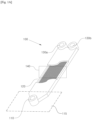
- Fig. 1A is a schematic view illustrating the constitution of the apparatus for separating a target object according to an embodiment of the present disclosure.
- the apparatus 100 for separating a target object may comprise an inlet 110, an injection unit 115, a passage unit 120, a target object obtaining unit 130a, a non-target object discharging unit 130b, etc.
- a fluid including microparticles may be injected into the apparatus 100 for separating the target object through the inlet 110.
- the injection unit 115 may refer to a fluid flow passage around the inlet 110.
- the target object may be separated intensively in a certain direction.
- the separated target object may be concentrated in the target object obtaining unit 130a.
- a non-target object that is not the target object may be concentrated in the non-target object discharging unit 130b.
- a fluid including microparticles may be injected into the inlet 110.
- the fluid may be injected with, for example, a tube, a syringe, a pipette, etc.
- the fluid may include whole blood for the purpose of obtaining leukocytes or plasma.
- the fluid may include cell culture media.
- the target object may be separated in a certain direction.
- the target object obtaining unit 130a may be provided at the end of the apparatus 100 for separating a target object in a predetermined direction, to obtain the separated target object.
- the non-target object discharging unit 130b may be provided at the end of the fluid passage of the apparatus 100 for separating a target object, to obtain the non-target object.
- the target object obtaining unit may be provided at the end of the fluid passage of the apparatus 100 for separating a target object
- the non-target object obtaining unit (not illustrated) may be provided at the end of the apparatus 100 for separating a target object in a predetermined direction.
- a channel may by formed such that the non-target object obtaining unit is provided in the middle of the fluid passage of the apparatus 100 for separating a target object.
- a plurality of non-target object obtaining units may be provided.
- the apparatus 100 for separating a target object is an apparatus for separating plasma
- plasma when blood is injected into the inlet 110, plasma may be concentrated in the target object obtaining unit 130a, and blood cells (e.g., leukocytes, erythrocytes, platelets, etc.) may be concentrated in the non-target object discharging unit 130b. Accordingly, even when plasma is separated by the apparatus for separating plasma, blood cells, etc., may be used without being discharged.
- blood cells e.g., leukocytes, erythrocytes, platelets, etc.
- the apparatus 100 for separating a target object is an apparatus for separating leukocytes
- leukocytes when blood is injected into the inlet 110, leukocytes may be extracted through the target object obtaining unit 130a, and erythrocytes may be extracted through the non-target object discharging unit 130b.
- one target object obtaining unit 130a and one non-target object discharging unit 130b are illustrated.
- the apparatus 100 for separating a target object may include two or more, e.g., four to ten, target object obtaining units.
- the apparatus 100 for separating a target object may include three or more, e.g., four to thirty, more specifically eight to fifteen, non-target object discharging units.
- the number of each of target object obtaining units and non-target object discharging units may be the same or different according to the target object.
- the micropattern in the apparatus 100 for separating the target object may be formed by a plurality of grooves.
- the shape of the groove may be determined according to the type of target object to be separated.
- the shape of the groove may include the height, width and length of the groove and the height of the passage unit 120, etc.
- the height and width of the groove may be within one half to two times the diameter of the target object
- the length of the groove may be within three times to ten times the diameter of the target object
- the height of the passage unit may be one time to three times the diameter of the target object.
- the diameter of microparticles may include the average diameter of microparticles.
- the pattern in the passage unit 120 may include a pattern in which grooves are arranged at certain intervals.
- the apparatus 100 for separating the target object may be manufactured from a polymer (polystyrene (PS), polycarbonate (PC), polymethylmethacrylate (PMMA), polydimethylsiloxane (PDMS), etc.).
- PS polystyrene
- PC polycarbonate
- PMMA polymethylmethacrylate
- PDMS polydimethylsiloxane
- the apparatus may separate and arrange the target object even when the apparatus has a hydrophobic surface, but preferably, the apparatus has a hydrophilic surface considering the flow of a fluid.
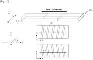
- the micropattern of the apparatus 100 for separating a target object may be formed at an angle of 45 to 135 degrees with respect to the main flow direction of a fluid.
- the angle ⁇ of the micropattern may range from about 45 degrees to about 135 degrees.
- the angle ⁇ of the micropattern may be determined according to the target object.
- the angle ⁇ of the micropattern in a channel of the apparatus for separating a target object may be about 45 degrees
- the angle ⁇ of the micropattern in another channel may be about 135 degrees.
- the micropattern may be formed by engraved structures of the apparatus 100 for separating a target object.
- the fluid moves in the direction perpendicular to the main flow direction of the fluid by the inclined engraved channel, and the target object may be concentrated in a predetermined direction and flow according to the angle of the micropattern.
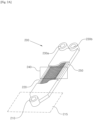
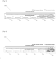
- Fig. 2A is a schematic view illustrating the constitution of the apparatus for separating a target object according to an embodiment of the present disclosure.
- the apparatus 200 for separating the target object further comprises a highway channel 250 and may have a different micropattern form, as compared with the apparatus 100 for separating a target object described above referring to Fig. 1A .
- Those other than said difference or features generated from said difference may have the properties of the apparatus 100 for separating a target object described above referring to Fig. 1 .
- Figs. 1A to 1C illustrate the apparatus 100 for separating a target object comprising a linear micropattern.
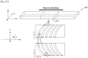
- Figs. 2A to 2C illustrate the apparatus 200 for separating a target object comprising a curved micropattern and a highway channel 250.
- the apparatus for separating a target object is not limited thereto, and any apparatus for separating a target object may comprise at least one of a linear micropattern, a curved micropattern and a highway channel.
- the apparatus 200 for separating a target object may comprise an inlet 210 through which a fluid including microparticles is injected, an injection unit 215 which is a fluid flow passage around the inlet 210, a passage unit 220 for concentrating a target object in a predetermined direction to flow while the injected fluid flows, a target object obtaining unit 230a for obtaining the target object concentrated in a predetermined direction, a non-target object discharging unit 230b, a highway channel 250, etc.
- one target object obtaining unit 230a is illustrated.
- the apparatus may comprise two target object obtaining units 230a, and three or more, e.g., four to ten, microparticles obtaining units.
- Fig. 2A illustrates one non-target object discharging unit 230b, but a plurality of the units may be provided.
- the apparatus 100 for separating a target object may comprise three or more, e.g., four to thirty, more specifically eight to fifteen, non-target object discharging units. The number of each of target object obtaining units and non-target object discharging units may be the same or different according to the target object.
- the target object obtaining unit 230a and the non-target object discharging unit 230b may be referred to as a first target object obtaining unit and a second target object acquiring unit, respectively, and a plurality of first target object obtaining units 230a may be provided and a plurality of second target object discharging units 230b may be provided.
- the inlet 210, the injection unit 215 and the passage unit 220 may respectively correspond to the inlet 110, the injection unit 115 and the passage unit 120 described above referring to Fig. 1A .
- the target object obtaining unit 230a and non-target object discharging unit 230b may respectively correspond to the target object obtaining unit 130a and the non-target object discharging unit 130b described above referring to Fig. 1A .
- the detailed description on the inlet 210, the injection unit 215, the passage unit 220, the target object obtaining unit 230a and the non-target object discharging unit 230b is omitted.
- the micropattern of the apparatus 200 for separating a target object may be different from the micropattern of the apparatus 100 for separating a target object in terms of structure, shape, arrangement location, number, etc.
- the micropattern may be formed by engraved structures having a groove shape in the direction perpendicular to the main flow direction of a fluid.
- At least one of the injection unit 215, the passage unit 220, the target object obtaining unit 230a and the non-target object discharging unit 230b may comprise a plurality of engraved structures having a groove shape in the direction perpendicular to the main flow direction of the fluid.
- the engraved structure may have an inclination inclined to a certain direction in which microparticles are to be separated, which means that the engraved structure may include an inclined structure.
- the inclination may include an inclination of 45 to 135 degrees with respect to the main flow direction of the fluid.
- the microparticles when a fluid including microparticles is injected into the apparatus 200 for separating a target object, the microparticles may move in the direction perpendicular to the inclined engraved structure to be concentrated in a predetermined direction and flow.
- each channel may start from the inlet and divide into several channels in the middle of the passage extending to target object obtaining units or non-target object discharging units, and accordingly additional channels may be formed.
- additional channels may be formed in the middle of the channel and have non-target object discharging units at the ends thereof.
- eight additional channels may be formed from the channel(s) starting from the inlet.
- the highway channel 250 may be formed in at least a portion of the area between the inlet 210 and the target object obtaining unit.
- no engraved structure is arranged in the highway channel 250, but a plurality of engraved structures may be arranged in an area other than the highway channel 250.
- the highway channel 250 will be described in detail referring to Figs. 2B , 3 and 4 .
- At least one of the injection unit 215, the passage unit 220, the target object obtaining unit 230a and the non-target object discharging unit 230b may comprise at least one pillar structure.
- the apparatus for separating a target object for separating leukocytes may have a pillar structure in the injection unit 215.
- the apparatus for separating a target object for separating plasma may have a pillar structure in the injection unit 215 and the passage unit 220.
- the apparatus for separating a target object for separating cells may have a pillar structure in all of the injection unit 215, the passage unit 220, the target object obtaining unit 230a and the non-target object discharging unit 230b.
- a plurality of pillar structures may be provided in each area. However, these are exemplary embodiments, and the apparatus for separating a target object may have several numbers of pillar structures in various areas. The pillar structure will be described in detail referring to Figs. 5 and 6 .
- Fig. 1A to Fig. 2C illustrate that the target object obtaining unit or non-target object discharging unit is arranged at the end of the apparatus for separating a target object.
- the target object obtaining unit and non-target object discharging unit may be located in the middle of the apparatus for separating a target object.
- the apparatus for separating a target object is an apparatus for separating plasma
- the plasma, which is the target object obtaining unit may be located at the end of the apparatus for separating plasma
- the leukocytes or erythrocytes which is the non-target
- discharging unit may be located in the middle of the separation apparatus.
- the apparatus for separating a target object is an apparatus for separating leukocytes
- the leukocytes, which is the target object obtaining unit may be located at the end of the separation apparatus
- the erythrocytes, which is the non-target, discharging unit may be located in the middle of the separation apparatus.
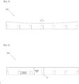
- Fig. 2B is a partial enlarged view of the apparatus for separating a target object of Fig. 2A .
- the passage unit may comprise a plurality of engraved structures and the highway channel 250.
- a plurality of engraved structures are arranged in at least a portion of the ceiling surface or bottom surface of the passage unit, so that the secondary flow may be induced in a direction perpendicular to the direction in which the fluid flows.
- the target object may be separated and concentrated based on the secondary flow.
- the engraved structure may have a predetermined inclination relative to the main flow direction of the fluid, and the inclination may be determined based on the main flow direction of the fluid and the certain direction in which microparticles are to be separated.
- the plurality of engraved structures may be disconnected from each other.
- the plurality of engraved structures may have a curved shape in the longitudinal direction, and the engraved structures may form a micropattern of curves.
- a micropattern formed by the plurality of engraved structures may have an arc shape.
- the curve may include at least a portion of a circle, at least a portion of an ellipse, at least a portion of a cycloid, any curved shape, etc.
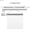
- the highway channel 250 is a ditch-type channel in the depth direction, along the direction in which microparticles are concentrated.
- the ditch-type channel may increase the concentration efficiency of the target object and decrease loss in the opposite direction. That is, the highway channel 250 may serve as a structure to keep microparticles.
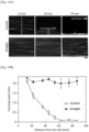
- the highway channel 250 may be formed in at least a portion of the area from the injection unit to the target object obtaining unit. According to an embodiment, the highway channel 250 may decrease fluid resistance and increase a local flow rate. Accordingly, a pressure is reduced, and the flow to the direction of the highway channel 250 occurs, so that the concentration efficiency of the target object may be increased.
- the function of the highway channel 250 will be described in more detail referring to Figs. 3 and 4 .
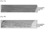
- the concentration efficiency of the target object will be described in more detail referring to Figs. 9A and 9B .
- Fig. 2C is a view explaining the inclination of the micropattern of the apparatus for separating a target object of Fig. 2A .
- the micropattern of the apparatus 200 for separating a target object may be formed in a curved shape.
- the curved shape may be an arc shape.
- a micropattern will be described with an example of the portion 270 of the passage unit.
- the angle ⁇ 1 at the starting point of the micropattern may range from 45 degrees to 135 degrees.
- the angle ⁇ 2 at the end point of the micropattern may range from 0 degree to 75 degrees or from 105 degrees to 180 degrees.
- the angles ⁇ 1 , ⁇ 2 of the micropattern may be determined according to the target object.
- the angle ⁇ 1 at the starting point of the micropattern may be 85 degrees and the angle ⁇ 2 at the end point may be 45 degrees. In another embodiment, the angle ⁇ 1 at the starting point of the micropattern may be 105 degrees and the angle ⁇ 2 at the end point may be 135 degrees. In another embodiment, the angle ⁇ 1 at the starting point of the micropattern in a channel of the apparatus for separating a target object may be 60 degrees and the angle ⁇ 2 at the end point of the micropattern may be 30 degrees; and the angle ⁇ 1 at the starting point of the micropattern in another channel may be 120 degrees and the angle ⁇ 2 at the end point may be 150 degrees.
- angles ⁇ 1 and ⁇ 2 of the micropattern may be selected properly according to the target object.
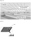
- Fig. 3 is a schematic cross-sectional view illustrating the apparatus for separating microparticles according to an embodiment of the present disclosure.
- the apparatus 300 for separating microparticles is described as an example of the apparatus for separating the target object.
- the embodiments of the apparatus 300 for separating microparticles of Fig. 3 may be applied not only to cells but also to various apparatuses for separating a target object such as plasma.
- the apparatus 300 for separating microparticles may comprise a plurality of engraved structures 310, 320, 330, 340, 350, 360.
- a fluid injected through the injection unit of the apparatus 300 for separating microparticles may move in a certain direction while flowing and microparticles may be concentrated in a certain direction.
- microparticles are concentrated in the right direction as an example.
- a fluid including microparticles may be concentrated in the right direction based on a pattern in a certain shape formed by a plurality of engraved structures.
- reverse streamlines may occur due to the plurality of engraved structures. In this case, the concentration efficiency of microparticles may be reduced by the reverse streamlines.
- an apparatus for separating microparticles comprising a highway channel which is a ditch-type channel in the depth direction may be provided on the side where microparticles are concentrated (e.g., right side in Fig. 3 ).
- Fig. 4 is a schematic cross-sectional view illustrating the apparatus for separating microparticles comprising a highway channel according to an embodiment of the present disclosure.
- the apparatus 400 for separating microparticles is described as an example of the apparatus for separating a target object.
- the embodiments of the apparatus 400 for separating microparticles of Fig. 4 may be applied to various apparatuses for separating a target object which is not only cells but also plasma.
- the apparatus 400 for separating microparticles may comprise a plurality of engraved structures 410, 420, 430, 440, 450 and a highway channel 460. In an embodiment, no engraved structure may be arranged in the highway channel 460.
Landscapes
- Chemical & Material Sciences (AREA)
- Health & Medical Sciences (AREA)
- Life Sciences & Earth Sciences (AREA)
- Engineering & Computer Science (AREA)
- General Health & Medical Sciences (AREA)
- Organic Chemistry (AREA)
- Zoology (AREA)
- Wood Science & Technology (AREA)
- Bioinformatics & Cheminformatics (AREA)
- Biotechnology (AREA)
- Chemical Kinetics & Catalysis (AREA)
- Clinical Laboratory Science (AREA)
- Genetics & Genomics (AREA)
- Dispersion Chemistry (AREA)
- Hematology (AREA)
- Analytical Chemistry (AREA)
- General Engineering & Computer Science (AREA)
- Biomedical Technology (AREA)
- Biochemistry (AREA)
- Microbiology (AREA)
- Fluid Mechanics (AREA)
- Physics & Mathematics (AREA)
- Medicinal Chemistry (AREA)
- Tropical Medicine & Parasitology (AREA)
- Virology (AREA)
- Sustainable Development (AREA)
- Cell Biology (AREA)
- Molecular Biology (AREA)
- Apparatus Associated With Microorganisms And Enzymes (AREA)
- Separation Of Solids By Using Liquids Or Pneumatic Power (AREA)
Applications Claiming Priority (2)
| Application Number | Priority Date | Filing Date | Title |
|---|---|---|---|
| KR20220052701 | 2022-04-28 | ||
| PCT/KR2023/003496 WO2023210966A1 (ko) | 2022-04-28 | 2023-03-16 | 타겟 대상물 분리 장치 및 방법 |
Publications (2)
| Publication Number | Publication Date |
|---|---|
| EP4516401A1 true EP4516401A1 (de) | 2025-03-05 |
| EP4516401A4 EP4516401A4 (de) | 2025-11-12 |
Family
ID=88024581
Family Applications (1)
| Application Number | Title | Priority Date | Filing Date |
|---|---|---|---|
| EP23725556.7A Pending EP4516401A4 (de) | 2022-04-28 | 2023-03-16 | Vorrichtung und verfahren zur trennung eines zielobjekts |
Country Status (5)
| Country | Link |
|---|---|
| US (1) | US20230348842A1 (de) |
| EP (1) | EP4516401A4 (de) |
| JP (1) | JP7590792B2 (de) |
| KR (2) | KR102656113B1 (de) |
| CN (1) | CN117320812A (de) |
Families Citing this family (1)
| Publication number | Priority date | Publication date | Assignee | Title |
|---|---|---|---|---|
| KR20260010565A (ko) * | 2024-07-11 | 2026-01-21 | 코스맥스 주식회사 | 지질 나노입자 제조용 미세유체칩, 이를 사용한 지질 나노입자의 제조방법 및 이를 통해 제조된 지질 나노입자의 용도 |
Family Cites Families (8)
| Publication number | Priority date | Publication date | Assignee | Title |
|---|---|---|---|---|
| WO2003044483A2 (en) * | 2001-11-15 | 2003-05-30 | Arryx, Inc. | Sample chip |
| US20120108787A1 (en) * | 2009-02-26 | 2012-05-03 | Nubiome, Inc. | Immobilization Particles for Removal of Microorganisms and/or Chemicals |
| KR20110005963A (ko) | 2009-07-13 | 2011-01-20 | 주식회사 나노엔텍 | 혈액 중에서 혈장 또는 혈청을 분리하는 미세유체 칩 |
| US9372134B2 (en) * | 2010-04-15 | 2016-06-21 | Cytogen Co., Ltd. | Microfluidic device and method for isolating target using same |
| CN113376364B (zh) * | 2015-08-10 | 2025-02-25 | 上海宜晟生物科技有限公司 | 步骤简化、小样品、快速、易使用的生物/化学分析装置和方法 |
| KR101791671B1 (ko) * | 2015-12-31 | 2017-11-20 | 주식회사 큐리오시스 | 미세입자 분리 및 정렬 장치, 및 그 방법 |
| US11262347B2 (en) * | 2018-05-03 | 2022-03-01 | Curiosis Co., Ltd. | Device and method for blood plasma separation |
| KR102038774B1 (ko) * | 2018-06-22 | 2019-10-30 | 울산과학기술원 | 자성 입자 분리장치 및 그를 이용한 바이오 정보 분석 방법, 바이오 표적 물질 분석 장치 |
-
2023
- 2023-03-16 EP EP23725556.7A patent/EP4516401A4/de active Pending
- 2023-03-16 JP JP2023533268A patent/JP7590792B2/ja active Active
- 2023-03-16 KR KR1020237028594A patent/KR102656113B1/ko active Active
- 2023-03-16 CN CN202380009246.2A patent/CN117320812A/zh active Pending
- 2023-03-16 KR KR1020237010153A patent/KR102574200B1/ko active Active
- 2023-05-30 US US18/203,349 patent/US20230348842A1/en active Pending
Also Published As
| Publication number | Publication date |
|---|---|
| JP2024520242A (ja) | 2024-05-24 |
| KR20230154180A (ko) | 2023-11-07 |
| US20230348842A1 (en) | 2023-11-02 |
| EP4516401A4 (de) | 2025-11-12 |
| JP7590792B2 (ja) | 2024-11-27 |
| KR102656113B1 (ko) | 2024-04-09 |
| KR102574200B1 (ko) | 2023-09-04 |
| CN117320812A (zh) | 2023-12-29 |
Similar Documents
| Publication | Publication Date | Title |
|---|---|---|
| US7897044B2 (en) | Fluid separation device | |
| JP5172946B2 (ja) | マイクロチャネルにおける粒子集束のためのシステムおよび方法 | |
| CN107110763B (zh) | 分选微流体装置中的颗粒 | |
| EP3409363A1 (de) | Partikeltrennvorrichtung und partikeltrennverfahren | |
| EP3902630B1 (de) | Mehrdimensionale doppelwendelvorrichtung und verwendungsverfahren dafür | |
| AU2016354119A1 (en) | Inertial droplet generation and particle encapsulation | |
| JP6757419B2 (ja) | 微細粒子分離または整列装置およびこれを用いた微細粒子分離または整列方法 | |
| US10697964B2 (en) | Liquid biopsy detection of leukemia using closed-loop microfluidics | |
| JP2023508465A (ja) | 粒子および細胞を処理するためのマイクロ流体カートリッジ | |
| EP4516401A1 (de) | Vorrichtung und verfahren zur trennung eines zielobjekts | |
| US20230033651A1 (en) | Microfluidic systems and methods for low-shear isolation of rare cells from large sample volumes | |
| CN119193286B (zh) | 一种螺旋结构惯性聚焦微流控细胞筛选装置及其筛选方法 | |
| US20250296019A1 (en) | System and method for automatically separating out target objects designed to not be exposed to outside | |
| US12403470B2 (en) | Microfluidic devices with multiple inlets and outlets | |
| US20230347345A1 (en) | Spiral inertial microfluidic devices and methods to remove contaminants | |
| TWI769507B (zh) | 具有階差之級聯設計微流體結構 | |
| KR20210102776A (ko) | 무세포 유전물질 분리, 농축 및 증폭을 위한 다기능 미세유체장치 및 이를 이용한 검출방법 | |
| JP7714318B2 (ja) | 分離デバイス | |
| KR20240105284A (ko) | 소변에서 입자를 분리하는 장치 및 방법 | |
| US11161113B2 (en) | Microchannel having a spiral geometry structured with asymmetrical curls for continuous separation of cancer cells from blood and enrichment thereof in the circulatory system | |
| KR20240102259A (ko) | 입자 분리 장치 및 입자 분리 방법 | |
| WO2023211901A1 (en) | Spiral inertial microfluidic devices and methods to remove contaminants | |
| Feng | Particle Manipulation and Separation in Inertial and Viscoelastic Flow |
Legal Events
| Date | Code | Title | Description |
|---|---|---|---|
| STAA | Information on the status of an ep patent application or granted ep patent |
Free format text: STATUS: UNKNOWN |
|
| STAA | Information on the status of an ep patent application or granted ep patent |
Free format text: STATUS: THE INTERNATIONAL PUBLICATION HAS BEEN MADE |
|
| PUAI | Public reference made under article 153(3) epc to a published international application that has entered the european phase |
Free format text: ORIGINAL CODE: 0009012 |
|
| STAA | Information on the status of an ep patent application or granted ep patent |
Free format text: STATUS: REQUEST FOR EXAMINATION WAS MADE |
|
| 17P | Request for examination filed |
Effective date: 20230531 |
|
| AK | Designated contracting states |
Kind code of ref document: A1 Designated state(s): AL AT BE BG CH CY CZ DE DK EE ES FI FR GB GR HR HU IE IS IT LI LT LU LV MC ME MK MT NL NO PL PT RO RS SE SI SK SM TR |
|
| DAV | Request for validation of the european patent (deleted) | ||
| DAX | Request for extension of the european patent (deleted) | ||
| A4 | Supplementary search report drawn up and despatched |
Effective date: 20251010 |
|
| RIC1 | Information provided on ipc code assigned before grant |
Ipc: B01L 3/00 20060101AFI20251006BHEP |