EP4516212A2 - Verfahren und systeme zur bestimmung, ob r-wellen-erkennungen als fehlerhaft aufgrund von t-wellen-übermessung (zwei) oder p-wellen-übermessung (pwo) klassifiziert werden müssen - Google Patents
Verfahren und systeme zur bestimmung, ob r-wellen-erkennungen als fehlerhaft aufgrund von t-wellen-übermessung (zwei) oder p-wellen-übermessung (pwo) klassifiziert werden müssen Download PDFInfo
- Publication number
- EP4516212A2 EP4516212A2 EP25152754.5A EP25152754A EP4516212A2 EP 4516212 A2 EP4516212 A2 EP 4516212A2 EP 25152754 A EP25152754 A EP 25152754A EP 4516212 A2 EP4516212 A2 EP 4516212A2
- Authority
- EP
- European Patent Office
- Prior art keywords
- wave
- wave detection
- detections
- interval duration
- pwo
- Prior art date
- Legal status (The legal status is an assumption and is not a legal conclusion. Google has not performed a legal analysis and makes no representation as to the accuracy of the status listed.)
- Granted
Links
Images




Classifications
-
- A—HUMAN NECESSITIES
- A61—MEDICAL OR VETERINARY SCIENCE; HYGIENE
- A61B—DIAGNOSIS; SURGERY; IDENTIFICATION
- A61B5/00—Measuring for diagnostic purposes; Identification of persons
- A61B5/24—Detecting, measuring or recording bioelectric or biomagnetic signals of the body or parts thereof
- A61B5/25—Bioelectric electrodes therefor
- A61B5/279—Bioelectric electrodes therefor specially adapted for particular uses
- A61B5/28—Bioelectric electrodes therefor specially adapted for particular uses for electrocardiography [ECG]
- A61B5/283—Invasive
- A61B5/29—Invasive for permanent or long-term implantation
-
- A—HUMAN NECESSITIES
- A61—MEDICAL OR VETERINARY SCIENCE; HYGIENE
- A61B—DIAGNOSIS; SURGERY; IDENTIFICATION
- A61B5/00—Measuring for diagnostic purposes; Identification of persons
- A61B5/24—Detecting, measuring or recording bioelectric or biomagnetic signals of the body or parts thereof
- A61B5/316—Modalities, i.e. specific diagnostic methods
- A61B5/318—Heart-related electrical modalities, e.g. electrocardiography [ECG]
- A61B5/346—Analysis of electrocardiograms
-
- A—HUMAN NECESSITIES
- A61—MEDICAL OR VETERINARY SCIENCE; HYGIENE
- A61B—DIAGNOSIS; SURGERY; IDENTIFICATION
- A61B5/00—Measuring for diagnostic purposes; Identification of persons
- A61B5/24—Detecting, measuring or recording bioelectric or biomagnetic signals of the body or parts thereof
- A61B5/316—Modalities, i.e. specific diagnostic methods
- A61B5/318—Heart-related electrical modalities, e.g. electrocardiography [ECG]
- A61B5/346—Analysis of electrocardiograms
- A61B5/349—Detecting specific parameters of the electrocardiograph cycle
-
- A—HUMAN NECESSITIES
- A61—MEDICAL OR VETERINARY SCIENCE; HYGIENE
- A61B—DIAGNOSIS; SURGERY; IDENTIFICATION
- A61B5/00—Measuring for diagnostic purposes; Identification of persons
- A61B5/24—Detecting, measuring or recording bioelectric or biomagnetic signals of the body or parts thereof
- A61B5/316—Modalities, i.e. specific diagnostic methods
- A61B5/318—Heart-related electrical modalities, e.g. electrocardiography [ECG]
- A61B5/346—Analysis of electrocardiograms
- A61B5/349—Detecting specific parameters of the electrocardiograph cycle
- A61B5/352—Detecting R peaks, e.g. for synchronising diagnostic apparatus; Estimating R-R interval
-
- A—HUMAN NECESSITIES
- A61—MEDICAL OR VETERINARY SCIENCE; HYGIENE
- A61B—DIAGNOSIS; SURGERY; IDENTIFICATION
- A61B5/00—Measuring for diagnostic purposes; Identification of persons
- A61B5/24—Detecting, measuring or recording bioelectric or biomagnetic signals of the body or parts thereof
- A61B5/316—Modalities, i.e. specific diagnostic methods
- A61B5/318—Heart-related electrical modalities, e.g. electrocardiography [ECG]
- A61B5/346—Analysis of electrocardiograms
- A61B5/349—Detecting specific parameters of the electrocardiograph cycle
- A61B5/353—Detecting P-waves
-
- A—HUMAN NECESSITIES
- A61—MEDICAL OR VETERINARY SCIENCE; HYGIENE
- A61B—DIAGNOSIS; SURGERY; IDENTIFICATION
- A61B5/00—Measuring for diagnostic purposes; Identification of persons
- A61B5/24—Detecting, measuring or recording bioelectric or biomagnetic signals of the body or parts thereof
- A61B5/316—Modalities, i.e. specific diagnostic methods
- A61B5/318—Heart-related electrical modalities, e.g. electrocardiography [ECG]
- A61B5/346—Analysis of electrocardiograms
- A61B5/349—Detecting specific parameters of the electrocardiograph cycle
- A61B5/355—Detecting T-waves
-
- A—HUMAN NECESSITIES
- A61—MEDICAL OR VETERINARY SCIENCE; HYGIENE
- A61B—DIAGNOSIS; SURGERY; IDENTIFICATION
- A61B5/00—Measuring for diagnostic purposes; Identification of persons
- A61B5/68—Arrangements of detecting, measuring or recording means, e.g. sensors, in relation to patient
- A61B5/6846—Arrangements of detecting, measuring or recording means, e.g. sensors, in relation to patient specially adapted to be brought in contact with an internal body part, i.e. invasive
- A61B5/6847—Arrangements of detecting, measuring or recording means, e.g. sensors, in relation to patient specially adapted to be brought in contact with an internal body part, i.e. invasive mounted on an invasive device
- A61B5/686—Permanently implanted devices, e.g. pacemakers, other stimulators, biochips
-
- A—HUMAN NECESSITIES
- A61—MEDICAL OR VETERINARY SCIENCE; HYGIENE
- A61B—DIAGNOSIS; SURGERY; IDENTIFICATION
- A61B5/00—Measuring for diagnostic purposes; Identification of persons
- A61B5/68—Arrangements of detecting, measuring or recording means, e.g. sensors, in relation to patient
- A61B5/6846—Arrangements of detecting, measuring or recording means, e.g. sensors, in relation to patient specially adapted to be brought in contact with an internal body part, i.e. invasive
- A61B5/6867—Arrangements of detecting, measuring or recording means, e.g. sensors, in relation to patient specially adapted to be brought in contact with an internal body part, i.e. invasive specially adapted to be attached or implanted in a specific body part
- A61B5/6869—Heart
-
- A—HUMAN NECESSITIES
- A61—MEDICAL OR VETERINARY SCIENCE; HYGIENE
- A61B—DIAGNOSIS; SURGERY; IDENTIFICATION
- A61B5/00—Measuring for diagnostic purposes; Identification of persons
- A61B5/72—Signal processing specially adapted for physiological signals or for diagnostic purposes
- A61B5/7221—Determining signal validity, reliability or quality
-
- A—HUMAN NECESSITIES
- A61—MEDICAL OR VETERINARY SCIENCE; HYGIENE
- A61B—DIAGNOSIS; SURGERY; IDENTIFICATION
- A61B5/00—Measuring for diagnostic purposes; Identification of persons
- A61B5/72—Signal processing specially adapted for physiological signals or for diagnostic purposes
- A61B5/7235—Details of waveform analysis
- A61B5/7264—Classification of physiological signals or data, e.g. using neural networks, statistical classifiers, expert systems or fuzzy systems
Definitions
- Non-vascular ICDs otherwise known as Subcutaneous ICDs (S-ICDs)
- S-ICDs Subcutaneous ICDs
- NV-ICDs Non-vascular ICDs
- S-ICDs rely on far-field subcutaneous EGMs.
- These far-field EGM which resemble surface ECGs, often include significantly large P-waves and T-waves that can be erroneously over-sensed as an R-wave.
- oversensing can ultimately result in false detections of ventricular tachycardia (VT) or ventricular fibrillation (VF), and/or other types of arrhythmia, potentially leading to inappropriate therapy delivery (e.g., shocks).
- VT ventricular tachycardia
- VF ventricular fibrillation
- VT and VF can be detected by measuring and comparing R-R intervals, or running averages thereof, to VT and VF detection thresholds. False positive VT and VF detections are highly undesirable, because they can lead to delivery of inappropriate therapy, such as shocks, which can premature deplete the battery of an ICD, and may be painful to the patient.
- P-wave and T-wave detection discriminator techniques are often unable or inadequate to correctly distinguish P-waves and T-waves from R-waves, often leading to over-sensed P-waves and over-sensed T-waves, both of which are types of false R-wave detections. Accordingly, there is a still a need for improved techniques for distinguishing P-waves and T-waves from R-waves, and for distinguishing over-sensed R-R intervals from true R-R intervals.
- the second TWO or PWO morphological criteria are met when the AUC(n) associated with the R-wave detection is at least the specified extent less than the AUC(n-2) associated with an R-wave detection that was two R-wave detections earlier, is not at least the specified extent less than the AUC(n-3) associated with the R-wave detection that was three R-wave detections earlier, and is at least the specified extent less than an AUC(n-4) associated with an R-wave detection that was four R-wave detections earlier.
- the specific morphological characteristic comprises a maximum slope (MS) associated with the R-wave detection.
- the first TWO or PWO morphological criteria are met when the MS(n) associated with the R-wave detection is at least a specified extent less than an MS(n-1) associated with an R-wave detection that was one R-wave detection earlier, is not at least the specified extent less than the MS(n-2) associated with the R-wave detection that was two R-wave detections earlier, and is at least the specified extent less than an MS(n-3) associated with an R-wave detection that was three R-wave detections earlier.
- the second TWO or PWO morphological criteria are met when the MS(n) associated with the R-wave detection is at least the specified extent less than the MS(n-2) associated with an R-wave detection that was two R-wave detections earlier, is not at least the specified extent less than the MS(n-3) associated with the R-wave detection that was three R-wave detections earlier, and is at least the specified extent less than an MS(n-4) associated with an R-wave detection that was four R-wave detections earlier.
- determining whether to classify the R-wave detection as a false R-wave detection comprises classifying the R-wave detection as a false R-wave detection in response to one of the first or the second TWO or PWO morphological criteria being met.
- the method further comprises comparing an R-R interval duration associated with the R-wave detection to an R-R interval duration associated with each R-wave detection in a third set of earlier detected R-wave detections to thereby determine whether first TWO or PWO temporal criteria are met, and in a fourth set of earlier detected R-wave detections to thereby determine whether second TWO or PWO temporal criteria are met, wherein the fourth set differs from the third set but may have some overlap with the third set.
- determining whether to classify the R-wave detection as a false R-wave detection is also based on whether one of the first or the second temporal criteria are met.
- the third set of earlier detected R-wave detections includes R-wave detections that were one and two R-wave detections earlier; and the second set of earlier detected R-wave detections includes R-wave detections that were two and three R-wave detections earlier.
- the first temporal criteria are met when the R-R interval duration D(n) associated with the R-wave detection is dissimilar to the R-R interval duration D(n-1) associated with the R-wave detection that was one R-wave detection earlier, and is similar to the R-R interval duration D(n-2) associated with the R-wave detection that was two R-wave detections earlier.
- determining whether to classify the R-wave detection as a false R-wave detection comprises classifying the R-wave detection as a false R-wave detection in response to both the first TWO or PWO morphological criteria and the first temporal criteria being met, or both the second TWO or PWO morphological criteria and the second TWO or PWO morphological criteria being met.
- a device comprises two or more electrodes, a sensing circuit, and a processor or controller.
- the sensing circuit is coupled to the two or more electrodes and configured to obtain one or more ECG or EGM signals indicative of electrical activity of a patient's heart.
- the processor or controller is configured to detect R-waves based on comparisons of the signal indicative of electrical activity of the patient's heart, or samples thereof, to an R-wave detection threshold.
- the processor or controller is configured to determine whether an R-wave detection should be classified as a false R-wave detection due to TWO or PWO.
- the processor or controller is configured to compare a specific morphological characteristic associated with the R-wave detection to the specific morphological characteristic associated with each R-wave detection in a first set of earlier detected R-wave detections to thereby determine whether first TWO or PWO morphological criteria are met, and in a second set of earlier detected R-wave detections to thereby determine whether second TWO or PWO morphological criteria are met, wherein the second set differs from the first set but may have some overlap with the first set. Additionally, the processor or controller is configured to determine whether to classify the R-wave detection as a false R-wave detection, based on whether one of the first or second TWO or PWO morphological criteria are met.
- the device is an implantable medial device (IMD).
- IMD implantable medial device
- the first set of earlier detected R-wave detections includes R-wave detections that were one, two, and three R-wave detections earlier; and the second set of earlier detected R-wave detections includes R-wave detections that were two, three, and four R-wave detections earlier.
- the processor or controller is configured to classify the R-wave detection as a false R-wave detection in response to one of the first or the second TWO or PWO morphological criteria being met.
- the specific morphological characteristic comprises a peak amplitude (A).
- the processor or controller is configured to determine that the first TWO or PWO morphological criteria are met when the peak amplitude A(n) associated with the R-wave detection is at least a specified extent lower than a peak amplitude A(n-1) associated with an R-wave detection that was one R-wave detection earlier, is not at least the specified extent lower than the peak amplitude A(n-2) associated with the R-wave detection that was two R-wave detections earlier, and is at least the specified extent lower than a peak amplitude A(n-3) associated with an R-wave detection that was three R-wave detections earlier.
- the specific morphological characteristic comprises an area under the curve (AUC).
- the processor or controller is configured to determine that the first TWO or PWO morphological criteria are met when the AUC(n) associated with the R-wave detection is at least a specified extent less than an AUC(n-1) associated with an R-wave detection that was one R-wave detection earlier, is not at least the specified extent less than the AUC(n-2) associated with the R-wave detection that was two R-wave detections earlier, and is at least the specified extent less than an AUC(n-3) associated with an R-wave detection that was three R-wave detections earlier.
- the specific morphological characteristic comprises a width (W) associated with the R-wave detection.
- the processor or controller is configured to determine that the first TWO or PWO morphological criteria are met when the width W(n) associated with the R-wave detection is at least a specified extent longer than a width W(n-1) associated with an R-wave detection that was one R-wave detection earlier, is not at least the specified extent longer than the width W(n-2) associated with the R-wave detection that was two R-wave detections earlier, and is at least the specified extent longer than a width W(n-3) associated with an R-wave detection that was three R-wave detections earlier.
- the specific morphological characteristic comprises a maximum slope (MS) associated with the R-wave detection.
- the processor or controller is configured to determine that the first TWO or PWO morphological criteria are met when the MS(n) associated with the R-wave detection is at least a specified extent less than an MS(n-1) associated with an R-wave detection that was one R-wave detection earlier, is not at least the specified extent less than an MS(n-2) associated with the R-wave detection that was two R-wave detections earlier, and is at least the specified extent less than an MS(n-3) associated with an R-wave detection that was three R-wave detections earlier.
- the processor or controller is configured to determine that the second TWO or PWO morphological criteria are met when the MS(n) associated with the R-wave detection is at least the specified extent less than the MS(n-2) associated with the R-wave detection that was two R-wave detections earlier, is not at least the specified extent less than the MS(n-3) associated with the R-wave detection that was three R-wave detections earlier, and is at least the specified extent less than an MS(n-4) associated with an R-wave detection that was four R-wave detections earlier.
- the controller or processor is configured to classify the R-wave detection as a false R-wave detection in response to one of the first or the second TWO or PWO morphological criteria being met.
- the controller or processor is also configured to compare an R-R interval duration associated with the R-wave detection to an R-R interval duration associated with each R-wave detection in a third set of earlier detected R-wave detections to thereby determine whether first TWO or PWO temporal criteria are met, and in a fourth set of earlier detected R-wave detections to thereby determine whether second TWO or PWO temporal criteria are met, wherein the fourth set differs from the third set but may have some overlap with the third set.
- the processor or controller is configured to determine whether to classify the R-wave detection as a false R-wave detection, also based on whether one of the first or the second temporal criteria are met.
- the third set of earlier detected R-wave detections includes R-wave detections that were one and two R-wave detections earlier; and the second set of earlier detected R-wave detections includes R-wave detections that were two and three R-wave detections earlier.
- the processor or controller is configured to determine that the first temporal criteria are met when the R-R interval duration D(n) associated with the R-wave detection is dissimilar to an R-R interval duration D(n-1) associated with the R-wave detection that was one R-wave detection earlier, and is similar to an R-R interval duration D(n-2) associated with the R-wave detection that was two R-wave detections earlier.
- the processor or controller is configured to determine that the second temporal criteria are met when the R-R interval duration D(n) associated with the R-wave detection is dissimilar to the R-R interval duration D(n-2) associated with the R-wave detection that was two R-wave detections earlier, and is similar to an R-R interval duration D(n-3) associated with an R-wave detection that was three R-wave detections earlier.
- the controller or processor is configured to classify the R-wave detection as a false R-wave detection in response to both the first TWO or PWO morphological criteria and the first temporal criteria being met, or both the second TWO or PWO morphological criteria and the second TWO or PWO morphological criteria being met.
- the controller or processor is further configured to adjust at least one parameter of the R-wave detection threshold based on results of determinations of whether R-wave detections should be classified as false R-wave detections due to TWO or PWO. For example, if at least a threshold number of R-wave detections within a specified number of R-wave detections (or within a specified amount of time) are classified as being false R-wave detections due to PWO, then an R-wave detection threshold can be increased to reduce the chance of PWO.
- a delay decay of an R-wave detection threshold can be prolonged to reduce the chance of TWO, wherein the decay delay defines the interval at which a magnitude or sensitivity level of an R-wave detection threshold remains at a constant level following expiration of a refractory period before the R-wave detection threshold begins decreasing in real time.
- Certain embodiments of the present technology are directed to a method for determining whether an R-wave detection should be classified as a false R-wave detection due to TWO or P-wave oversensing PWO, the method comprising: obtaining a peak amplitude A(n) associated with an R-wave detection and a respective peak amplitude for other R-wave detections preceding the R-wave detection; determining whether first TWO or PWO morphological criteria are met by determining whether the peak amplitude A(n) associated with the R-wave detection is at least a specified extent lower than a peak amplitude A(n-1) associated with an R-wave detection that was one R-wave detection earlier, is not at least the specified extent lower than the peak amplitude A(n-2) associated with the R-wave detection that was two R-wave detections earlier, and is at least the specified extent lower than a peak amplitude A(n-3) associated with an R-wave detection that was three R-wave detections earlier; determining whether second TWO or PWO morphological criteria are
- the processor or controller is also configured to determine whether second TWO or PWO morphological criteria are met by determining whether the peak amplitude A(n) associated with the R-wave detection is at least the specified extent lower than the peak amplitude A(n-2) associated with the R-wave detection that was two R-wave detections earlier, is not at least the specified extent lower than the peak amplitude A(n-3) associated with the R-wave detection that was three R-wave detections earlier, and is at least the specified extent lower than a peak amplitude A(n-4) associated with an R-wave detection that was four R-wave detections earlier.
- the processor or controller is configured to classify the R-wave detection as a false R-wave detection in response to one of the first or the second TWO or PWO morphological criteria being met.
- each cardiac cycle represented within an EGM or ECG typically includes a P-wave, followed by a QRS complex, followed by a T-wave, with the QRS complex including Q-, R-, and S-waves.
- the P-wave is caused by depolarization of the atria.
- atrial contraction which is indicated by a slight rise in atrial pressure contributing to further filling of the ventricle.
- ventricular depolarization as indicated by the QRS complex, with ventricular depolarization initiating contraction of the ventricles resulting in a rise in ventricular pressure until it exceeds the pulmonary and aortic diastolic pressures to result in forward flow as the blood is ejected from the ventricles.
- EGM EGM signal
- EGM waveform ECG signal
- ECG waveform ECG waveform
- the R-wave is the largest wave in the QRS complex, and it often identified by comparing samples of an EGM or ECG to an R-wave threshold, wherein the R-wave threshold is typically variable and typically depends on peak amplitudes of detected R-waves.
- Various measurements can be obtained based on the EGM or ECG waveform, including measurements of R-R intervals, where an R-R interval is the duration between a pair of consecutive R-waves.
- a common technique for detecting AF is based on measures of R-R interval variability
- common techniques for detecting VT and VF is based on measures of R-R interval durations or running averages thereof.
- T-waves and/or P-waves are falsely identified as R-waves, because they are over-sensed, false R-R intervals can be identified which have a high variability, leading to false detections of AF.
- Overs-sensed T-waves and/or P-waves can also lead to false detections of VT and VF.
- over-sensed P-waves and/or over-sensed T-waves can lead to false positive AF detections, false positive VT detections, and/or false positive VF detections.
- An over-sensed P-wave refers to a P-wave that is falsely identified as an R-wave.
- an over-sensed T-wave refers to a T-wave that is falsely identified as an R-wave. Accordingly, it can be appreciated that over-sensed T-waves and over-sensed P-waves are examples of false R-wave detections that are due to T-wave oversensing (TWO) and P-wave oversensing (PWO), respectively.
- TWO T-wave oversensing
- PWO P-wave oversensing
- Certain embodiments of the present technology relate to methods and devices that use R-R interval durations and peak amplitudes (or other types of temporal and/or morphological characteristics) associated with R-wave detections to determine whether P-wave and/or T-wave oversensing has occurred, and more generally, to distinguish true R-wave detections from false R-wave detections.
- Such embodiments can beneficially be used, for example, to prevent or reject false positive VF detections, to prevent or reject false positive VT detections, and/or to prevent or reject false positive AF detections, but are not limited thereto. Accordingly, it would be appreciated that such embodiments can be used to provide for improved delivery of therapy and/or improved use of clinical resources.
- the embodiment can be used to avoid delivery of a defibrillation shock that is unnecessary, painful to the patient, and prematurely depletes power from a battery of an IMD.
- the embodiment can be used to avoid delivery of anti-tachycardia pacing (ATP) that is unnecessary, may accelerate sinus rhythm to VT or VF, and prematurely depletes power from a battery of an IMD.
- ATP anti-tachycardia pacing
- the embodiment can be used to improve the use of clinical resources, where clinicians are tasked with analyzing AF episodes that are detected and recorded by an IMD.
- a true R-R interval refers to an actual R-R interval, which is the interval between two actual R-waves.
- a false R-R interval refers to an interval that is mistakenly identified as an R-R interval, but is not an actual R-R interval.
- Example types of intervals that may be mistakenly identified as an R-R interval, and thus are examples of false R-R intervals include, but are not limited to, P-R intervals, R-T intervals, P-T intervals, and T-P intervals.
- a P-R interval can be mistakenly identified as an R-R interval where a P-wave is over-sensed.
- An R-R interval is the duration between two consecutive R-wave detections, and thus, an R-R interval can also be referred to herein as an R-R duration. More generally, an R-wave detection can be said to have an associated R-R interval duration, which is the duration between the time of the R-wave detection and the time of the immediately preceding R-wave detection. When discussing an R-wave detection, the immediately preceding R-wave detection can also be referred to as an R-wave detection that was one R-wave detection earlier.
- the duration that is associated with an R-wave detection can be determined by a processor of an IMD, as could other temporal and/or morphological characteristics that are associated with the R-wave detection.
- the morphological characteristic associated with an R-wave detection which is used to determine whether or not the R-wave detection should be classified as a false R-wave detection
- the temporal characteristic associated with an R-wave detection which is used to determine whether or not the R-wave detection should be classified as a false R-wave detection
- the associated R-R interval duration is the duration (i.e., length of time) between the R-wave detection and an R-wave detection that was one R-wave detection earlier.
- Certain embodiments of the present technology described herein rely on various criteria to identify a false R-wave detection.
- One criteria which can be referred to as first TWO or PWO temporal criteria, is that an R-R interval duration D(n) associated with an R-wave detection that is actually an over-sensed P-wave or T-wave should be dissimilar to an R-R interval duration associated with an R-wave detection D(n-1) that was one R-wave detection earlier, and should be similar an R-R interval duration associated with an R-wave detection D(n-2) that was two R-wave detections earlier.
- the term “dissimilar” when used herein to describe how two R-R interval durations compare means that a difference in the durations, however calculated, is beyond some specified threshold.
- the term “similar” when used herein to describe how two R-R interval durations compare means that a difference in the durations, however calculated, is within some specified threshold. If two R-R interval durations are not similar to one another, because the difference in their durations is beyond the specified threshold, then it can also be said that the two R-R interval durations are dissimilar.
- TWO or PWO morphological criteria Another criteria, which can be referred to as first TWO or PWO morphological criteria, is that a peak amplitude A(n) associated with an R-wave detection that is actually an over-sensed P-wave or T-wave should be lower than a peak amplitude associated with an R-wave detection that was one R-wave detection earlier A(n-1), lower than a peak amplitude A(n-3) of an R-wave detection that was three R-wave detections earlier A(n-3), but not lower than a peak amplitude of an R-wave detection that was two R-wave detections earlier A(n-2).
- the term “lower” when used herein to describe how two peak amplitudes compare means a value of one peak amplitude is less than a value of another peak amplitude by at least some specified threshold, or that a ratio of the values of the two peak amplitudes is below some specified threshold.
- TWO or PWO which refers to T-wave oversensing or P-wave oversensing, can alternatively be written as TWO/PWO.
- the R-wave detection is classified as being a false R-wave detection, which may be caused by either P-wave oversensing (PWO) or T-wave oversensing (TWO).
- PWO P-wave oversensing
- TWO T-wave oversensing
- the first TWO or PWO temporal criteria and the first TWO or PWO morphological criteria can both be met, e.g., where an R-wave detection actually corresponds to a T-wave, an R-wave detection that corresponds to one R-wave detection earlier is a true R-wave, an R-wave detection that corresponds to two R-wave detections earlier is a T-wave, and an R-wave detection that corresponds to three R-wave detections earlier is a true R-wave.
- An example of this is shown in FIG. 1 , discussed below.
- the first TWO or PWO temporal criteria and the first TWO or PWO morphological criteria can both be met, e.g., where an R-wave detection actually corresponds to a P-wave, an R-wave detection that corresponds to one R-wave detection earlier is a true R-wave, an R-wave detection that corresponds to two R-wave detections earlier is a P-wave, and an R-wave detection that corresponds to three R-wave detections earlier is a true R-wave.
- the R-wave detection may still be classified as a false R-wave detection if both of second TWO or PWO temporal criteria and second TWO or PWO morphological criteria, which are discussed below, are met.
- the second TWO or PWO temporal criteria is that an R-R interval duration D(n) associated with an R-wave detection that is actually an over-sensed P-wave or T-wave should be different than (i.e., dissimilar to) an R-R interval duration associated with an R-wave detection that was two R-wave detections earlier D(n-2), and should be similar an R-R interval duration associated with an R-wave detection that was three R-wave detections earlier D(n-3).
- the second TWO or PWO morphological criteria is that a peak amplitude A(n) associated with an R-wave detection that is actually an over-sensed P-wave or T-wave should be lower than a peak amplitude associated with an R-wave detection that was two R-wave detections earlier A(n-2), lower than a peak amplitude of an R-wave detection that was four R-wave detections earlier A(n-4), but not lower than a peak amplitude of an R-wave detection that was three R-wave detections earlier A(n-3).
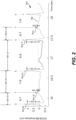
- the second TWO or PWO temporal criteria and the second TWO or PWO morphological criteria can both be met, e.g., where an R-wave detection actually corresponds to a T-wave, an R-wave detection that corresponds to one R-wave detection earlier is a true R-wave, an R-wave detection that corresponds to two R-wave detections earlier is a true R-wave, an R-wave detection that corresponds to three R-wave detections earlier is a T-wave, and an R-wave detection that corresponds to four R-wave detections earlier is a true R-wave.
- An example of this is shown in FIG. 2 , discussed below.
- the second TWO or PWO temporal criteria and the second TWO or PWO morphological criteria can both be met, e.g., where an R-wave detection actually corresponds to a P-wave, an R-wave detection that corresponds to one R-wave detection earlier is a true R-wave, an R-wave detection that corresponds to two R-wave detections earlier is a true R-wave, an R-wave detection that corresponds to three R-wave detections earlier is a P-wave, and an R-wave detection that corresponds to four R-wave detections earlier is a true R-wave.
- an R-wave detection is classified as a false R-wave if either: the first TWO or PWO temporal criteria and the first TWO or PWO morphological criteria are both met; or the second TWO or PWO temporal criteria and the second TWO or PWO morphological criteria are both met. These criteria are described in additional detail below with reference to FIGS. 1 and 2 .
- FIG. 1 shows an example EGM signal 101 sensed by an IMD, such as an S-ICD.
- the R-wave detection that is being analyzed is the R-wave detection labeled R(n) in FIG. 1 , which has an associated R-R interval duration D(n), and an associated peak amplitude A(n).
- the first TWO or PWO temporal criteria is that an R-R interval duration D(n) associated with an R-wave detection that is actually an over-sensed P-wave or T-wave should be different than an R-R interval duration associated with an R-wave detection that was one R-wave detection earlier D(n-1), and should be similar an R-R interval duration associated with an R-wave detection that was two R-wave detections earlier D(n-2).
- a percentage difference between D(n) and D(n-1) is determined and compared to a corresponding percentage threshold, e.g., 10%.
- a percentage difference between D(n) and D(n-2) is determined and compared to the corresponding percentage threshold, e.g., 10%.
- % Difference D(n) vs. D(n-1) 100 *
- / D(n) 100 *
- / D(n) 100 *
- / 0.30 3.3 % ⁇ 10%.
- the first TWO or PWO morphological criteria is that a peak amplitude A(n) associated with an R-wave detection that is actually an over-sensed P-wave or T-wave should be lower than a peak amplitude A(n-1) associated with an R-wave detection that was one R-wave detection earlier, not lower than a peak amplitude A(n-2) of an R-wave detection that was two R-wave detections earlier, and lower than a peak amplitude A(n-3) of an R-wave detection that was three R-wave detections earlier.
- a ratio of A(n) to A(n-1) is determined and compared to a corresponding ratio threshold, e.g., 0.4.
- a ratio of A(n) to A(n-2) is determined and compared to the corresponding ratio threshold, e.g., 0.4.
- a ratio of A(n) to A(n-3) is determined and compared to the corresponding ratio threshold, e.g., 0.4.
- Ratio A(n) vs. A(n-1) A(n) / A(n-1);
- Ratio A(n) vs. A(n-2) A(n) / A(n-2); and
- both the first TWO or PWO temporal criteria and the first TWO or PWO morphological criteria are met, and thus, using an embodiment of the present technology the R-wave detection R(n) would be classified as a false R-wave detection that is due to TWO or PWO.
- FIG. 2 shows an example EGM signal 201 sensed by an IMD, such as an S-ICD.
- the R-wave detection that is being analyzed is the R-wave detection labeled R(n) in FIG. 2 , which has an associated R-R interval duration D(n), and an associated peak amplitude A(n).
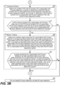
- steps 332 and 342 involve determining whether the peak amplitude A(n) associated with the R-wave detection is at least a specified extent lower than a peak amplitude A(n-1) associated with an R-wave detection that was one R-wave detection earlier, is at least the specified extent lower than a peak amplitude A(n-3) associated with an R-wave detection that was three R-wave detections earlier, and is not at least the specified extent lower than the peak amplitude A(n-2) associated with the R-wave detection that was two R-wave detections earlier.
- step 342 If the answer to the determination at step 342 is Yes, then it is determined that the first TWO or PWO morphological criteria are met, and flow goes to step 352 and the R-wave detection is classified as a false R-wave detection which is caused by TWO or PWO. If the answer to the determination at step 342 is No, that means the first TWO or PWO morphological criteria are not met, and flow goes to steps 362 and 372 in FIG. 3B to determine whether the second TWO or PWO temporal criteria and the second TWO or PWO morphological criteria are met. It is noted that while steps 332 and 342 are shown as two steps, these two steps can be combined into a single step. It is also noted that these steps can be made up of multiple sub-steps, as can be appreciated from FIG. 4A discussed below.
- step 362 involves determining whether the R-R interval duration D(n) associated with the R-wave detection is similar or dissimilar to the R-R interval duration D(n-2) associated with the R-wave detection that was two R-wave detections earlier, and similar or dissimilar to an R-R interval duration D(n-3) associated with an R-wave detection that was three R-wave detections earlier.
- Step 372 involves determining whether the R-R interval duration D(n) associated with the R-wave detection is dissimilar to the R-R interval duration D(n-2) associated with the R-wave detection that was two R-wave detections earlier, and similar to the R-R interval duration associated with the R-wave detection D(n-3) that was three R-wave detections earlier.
- steps 382 and 392 can be performed before steps 362 and 372, or more generally, that a determination of whether the second TWO or PWO morphological criteria are met can be performed prior to a determination of whether the second TWO or PWO temporal criteria are met.
- step 302 is the same as step 302 described above with reference to FIG. 3A , and thus need not be described again.
- Steps 404, 406, 408, and 410 can be used to perform steps 312 and 322 discussed above, and more generally, can be used to determine whether the first TWO or PWO temporal criteria are met.
- Step 422 involves determine whether the Ratio_3 ⁇ R_TH (e.g., 0.4). If the answers to the determinations at steps 418, 420 and 422 are all Yes, that means the first TWO or PWO morphological criteria are met, and then flow goes to step 352. At step 352 the R-wave detection is classified as a false R-wave detection which is caused by P-wave or T-wave oversensing. If the answer to at least one of the determinations at step 418, 420 and 422 is No, that means the first TWO or PWO morphological criteria are not met, and flow goes to steps 424 through 430 (in FIG. 4B ) to determine whether the second TWO or PWO temporal criteria are met.
- the Ratio_3 ⁇ R_TH e.g., 0.4
- steps 424, 426, 428, and 430 can be used to perform steps 362 and 372 discussed above, and more generally, can be used to determine whether the second TWO or PWO temporal criteria are met.
- Step 428 involves determining whether %Diff_2 > %TH (e.g., 10%).
- Step 430 involves determining whether %Diff_3 ⁇ %TH (e.g., 10%). If the answers to the determinations at steps 428 and 430 are both Yes, that means the second TWO or PWO temporal criteria are met, and then flow goes to steps 432 through 442, to determine whether the second TWO or PWO morphological criteria are met. If the answer to at least one of the determinations at step 428 and 430 is No, that means the second TWO or PWO temporal criteria are not met, and flow goes to step 394, at which the R-wave detection is not classified as a false R-wave detection.
- %Diff_3 ⁇ %TH e.g. 10%
- steps 432 through 442 can be used to perform steps 382 and 392 discussed above, and more generally, can be used to determine whether the second TWO or PWO morphological criteria are met.
- Step 438 involves determining whether the Ratio_2 ⁇ R_TH (e.g., 0.4).
- Step 440 involves determining whether the Ratio_3 > R_TH (e.g., 0.4).
- Step 422 involves determine whether the Ratio_4 ⁇ R_TH (e.g., 0.4). If the answers to the determinations at steps 438, 440 and 442 are all Yes, that means the second TWO or PWO morphological criteria are met, and then flow goes to step 352 (in FIG. 4A ).
- the R-wave detection is classified as a false R-wave detection which is caused by P-wave or T-wave oversensing.
- step 438, 440 and 442 If the answer to at least one of the determinations at step 438, 440 and 442 is No, that means the second TWO or PWO morphological criteria are not met, and flow goes to step 394, at which the R-wave detection is not classified as a false R-wave detection.
- an R-wave detection is classified as a false R-wave detection (caused by P-wave or T-wave oversensing) if either: the first TWO or PWO temporal criteria and the first TWO or PWO morphological criteria are both met; or if the second TWO or PWO temporal criteria and the second TWO or PWO morphological criteria are both met.
- R-R interval durations associated with R-wave detections are compared to one another. The R-R interval durations are examples of temporal characteristics of the R-wave detections.
- peak amplitudes associated with R-wave detections are compared to one another.
- the peak amplitudes are examples of morphological characteristics associated with the R-wave detections.
- other types of morphological characteristics associated with R-wave detections can be compared to one another instead of (or in addition to) peak amplitudes for the purpose of determining whether an R-wave detection should be classified as a false R-wave detection (caused by PWO or TWO).
- temporal characteristics of R-wave detections can be compared to one another, without comparing morphological characteristics of R-wave detections to one another, for the purpose of determining whether an R-wave detection should be classified as false R-wave detection (caused by P-wave or T-wave oversensing).
- R-R interval durations associated with R-wave detections are compared to one another to determine whether one of the first TWO or PWO temporal criteria or the second TWO or PWO temporal criteria are met, and if so, then an R-wave detection is classified as a false R-wave detection (caused by PWO or TWO).
- step 502 involves obtaining an associated R-R interval duration D(n) for an R-wave detection.
- Steps 312 and 322 are used to determine whether the first TWO or PWO temporal criteria are met. If the first TWO or PWO temporal criteria are met, the answer to the determination at step 322 will be Yes, and the R-wave detection will be classified as a false R-wave detection at step 352. If the first TWO or PWO temporal criteria are not met, then steps 362 and 372 are used to determine whether the second TWO or PWO temporal criteria are met.
- Step 372 If the second TWO or PWO temporal criteria are met, the answer to the determination at step 372 will be Yes, and the R-wave detection will be classified as a false R-wave detection at step 352. If neither the first TWO or PWO temporal criteria nor the second TWO or PWO temporal criteria are met, then the R-wave detection will not be classified as a false R-wave detection at step 394. Steps 312, 322, 352, 362, 372, and 394, which are shown in FIG. 5 , were described above with reference to FIG. 3 , and thus, need not be described again. Some additional example details of how these steps can be performed were described above with reference to FIG. 4 .
- morphological characteristics of R-wave detections can be compared to one another, without comparing temporal characteristics of R-wave detections to one another, for the purpose of determining whether an R-wave detection should be classified as false R-wave detection (caused by P-wave or T-wave oversensing).
- peak amplitudes associated with R-wave detections are compared to one another to determine whether one of the first TWO or PWO morphological criteria or the second morphological criteria are met, and if so, then an R-wave detection is classified as a false R-wave detection (caused by P-wave or T-wave oversensing).
- An example high level flow diagram for such an embodiment is shown in FIG. 6 .
- step 602 involves obtaining an associated peak amplitude A(n) for an R-wave detection.
- Steps 332 and 342 are used to determine whether the first TWO or PWO morphological criteria are met.
- the R-wave detection will be classified as a false R-wave detection at step 352. If the first TWO or PWO morphological criteria are not met, then steps 382 and 392 are used to determine whether the second TWO or PWO morphological criteria are met. If the second TWO or PWO morphological criteria are met, the answer to the determination at step 392 will be Yes, and the R-wave detection will be classified as a false R-wave detection at step 352. If neither the first TWO or PWO morphological criteria nor the second TWO or PWO morphological criteria are met, then the R-wave detection will not be classified as a false R-wave detection at step 394.
- Steps 332, 342, 352, 382, 392, and 394 which are shown in FIG. 6 , were described above with reference to FIG. 3 , and thus, need not be described again. Some additional example details of how these steps can be performed were described above with reference to FIG. 4 .
- FIG. 7 includes a high level flow diagram that explains more generally how first and second TWO or PWO morphological criteria can be used to determine whether an R-wave detection should be classified as a false R-wave detection due to TWO or PWO.
- step 702 involves obtaining, for an R-wave detection, an associated specific type of morphological characteristic.
- the specific type of morphological characteristic comprises peak amplitude.
- step 702 is the same as step 602 described above.
- Alternative types of morphological characteristics that can be obtained at step 702 include, but are not limited to, an area under the curve (AUC) associated with the R-wave detection, a width (W) associated with the R-wave detection, or a maximum slope (MS) associated with the R-wave detection.
- the width (W) can be, e.g., a measure of a full width at R-wave threshold detection crossings, a full width at half maximum (FWHM), or a half width at half maximum (HWHM) associated with respective R-wave detections, but is not limited thereto.
- the maximum slope (MS) associated with an R-wave detection can be determined by determining a maximum derivative (dV/dt) of an ECG or EGM signal within a window surrounding or following the R-wave detection, as noted above.
- a window can be, e.g., a window that is from 50 milliseconds (msec) prior to the R-wave detection to 50 msec following the R-wave detection, but is not limited thereto.
- step 732 involves comparing the specific morphological characteristic (e.g., peak amplitude) associated with the R-wave detection to the specific morphological characteristic associated with each R-wave detection in a first set of earlier detected R-wave detections to thereby determine whether first TWO or PWO morphological criteria are met.
- the first set of earlier detected R-wave detections includes R-wave detections that were one, two, and three R-wave detections earlier.
- the specific type of morphological characteristic comprises peak amplitude
- the first set of earlier detected R-wave detections includes R-wave detections that were one, two, and three R-wave detections earlier, then step 732 is the same as step 332 described above.
- step 742 there is a determination of whether the first TWO or PWO morphological criteria are met. If the answer to the determination at step 742 is Yes, then flow goes to step 752, and the R-wave detection is classified as a false R-wave detection which is caused by TWO or PWO. If the answer to the determination at step 742 is No, then flow goes to step 782.
- step 782 involves comparing the specific morphological characteristic (e.g., peak amplitude) associated with the R-wave detection to the specific morphological characteristic associated with each R-wave detection in a second set of earlier detected R-wave detections to thereby determine whether the second TWO or PWO morphological criteria are met, wherein the second set differs from the first set but may have some overlap with the first set.
- the second set of earlier detected R-wave detections includes R-wave detections that were two, three, and four R-wave detections earlier.
- step 782 is the same as step 382 described above.
- step 792 there is a determination of whether the second TWO or PWO morphological criteria are met. If the answer to the determination at step 792 is Yes, then flow goes to step 752, and the R-wave detection is classified as a false R-wave detection which is caused by TWO or PWO. If the answer to the determination at step 792 is No, then flow goes to step 794, and the R-wave detection is not classified as a false R-wave detection.
- one of the above described techniques for determining whether an R-wave detection should be classified as a false R-wave detection can be performed in real time, such that each time an R-wave detection occurs, there is a determination whether the R-wave detection should be classified as a false R-wave detection prior to the next R-wave detection occurring.
- the IMD can detect a VF episode and deliver defibrillation shock therapy to attempt to convert the VF episode to normal sinus rhythm. This can be achieved, e.g., by incrementing an appropriate counter, such as a VT counter or a VF counter, in response to an R-wave detection being preliminarily classified as being a VT type or a VF type of rhythm.
- an appropriate counter such as a VT counter or a VF counter
- An embodiment of the invention relates to a device, such as an IMD.
- the device comprises two or more electrodes, a sensing circuit and a processor or controller.
- the sensing circuit is coupled to the two or more electrodes and configured to obtain a signal indicative of electrical activity of a patient's heart.
- R-wave detections are detected based on comparisons of the signal indicative of electrical activity of the patient's heart, or samples thereof, to an R-wave detection threshold.
- the processor or controller is configured to compare a specific morphological characteristic associated with the R-wave detection to the specific morphological characteristic associated with each R-wave detection in a first set of earlier detected R-wave detections to thereby determine whether first TWO or PWO morphological criteria are met, and in a second set of earlier detected R-wave detections to thereby determine whether second TWO or PWO morphological criteria are met, wherein the second set differs from the first set but may have some overlap with the first set.
- the processor or controller is also configured to determine whether to classify the R-wave detection as a false R-wave detection, based on whether one of the first or second TWO or PWO morphological criteria are met.
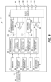
- FIG. 8 shows a block diagram of one embodiment of an IMD that is implanted into a patient in accordance with a certain embodiment of the present technology.
- the IMD 801 may be implemented as a full-function biventricular pacemaker, equipped with both atrial and ventricular sensing and pacing circuitry for four chamber sensing and stimulation therapy (including both pacing and shock treatment).
- the IMD 801 may provide full-function cardiac resynchronization therapy.
- the IMD 801 may be implemented with a reduced set of functions and components.
- the IMD may be implemented without pacing, e.g., if the IMD is an ICM.
- the IMD 801 can be coupled to one or more leads for single chamber or multi-chamber pacing and/or sensing.
- the IMD 801 can be an LCP that includes electrodes located on or very close to a housing 800 of the IMD 801.
- the IMD 801 has a housing 800 to hold the electronic/computing components.
- the housing 800 (which is often referred to as the "can”, “case”, “encasing”, or “case electrode”) may be programmably selected to act as the return electrode for certain stimulus modes.
- the housing 800 may further include a connector (not shown) with a plurality of terminals 802, 804, 806, 808, and 810.
- the terminals may be connected to electrodes that are located in various locations on the housing 800 or to electrodes located on leads.
- the electrodes to which the terminals 802, 804, 806, 808, and 810 are connected can also be referenced, respectively, using reference numbers 802, 804, 806, 808, and 810, and the case electrode can be referenced as case electrode 800.
- the IMD 801 further includes a pulse generator 822 that generates stimulation pulses and communication pulses for delivery by two or more electrodes coupled thereto.
- the pulse generator 822 is controlled by the microcontroller 820 via a control signal 824.
- the pulse generator 822 may be coupled to the select electrode(s) via an electrode configuration switch 826, which includes multiple switches for connecting the desired electrodes to the appropriate I/O circuits, thereby facilitating electrode programmability.
- the switch 826 is controlled by a control signal 828 from microcontroller 820.
- the IMD may include multiple pulse generators, similar to the pulse generator 822, where each pulse generator is coupled to two or more electrodes and controlled by the microcontroller 820 to deliver select stimulus pulse(s) to the corresponding two or more electrodes.
- the microcontroller 820 is illustrated as including timing control circuitry 832 to control the timing of the stimulation pulses (e.g., pacing rate, atrio-ventricular (AV) delay, atrial interconduction (A-A) delay, or ventricular interconduction (V-V) delay, etc.).
- the timing control circuitry 832 may also be used for the timing of refractory periods, blanking intervals, noise detection windows, evoked response windows, alert intervals, marker channel timing, and so on.
- the microcontroller 820 also has an arrhythmia detector 834 for detecting arrhythmia conditions and a morphology detector 836.
- the microcontroller 820 may further include other dedicated circuitry and/or firmware/software components that assist in monitoring various conditions of the patient's heart and managing pacing therapies.
- the microcontroller 820 is also shown as including an oversensing detector 840, which can be used to perform any of the embodiments of the present technology described above with reference to FIGS. 1-7 .
- the oversensing detector 840 can more generally be implemented using hardware, software, firmware, and/or combinations thereof.
- the microcontroller can include a processor.
- the microcontroller, and/or the processor thereof, can be used to perform the methods of the present technology described herein.
- the IMD 801 can be further equipped with a communication modem (modulator/demodulator) to enable wireless communication with the remote slave pacing unit.
- the modem may include one or more transmitters and two or more receivers. In one implementation, the modem may use low or high frequency modulation. As one example, modem may transmit implant-to-implant (i2i) messages and other signals through conductive communication between a pair of electrodes.
- a modem may be implemented in hardware as part of the microcontroller 820, or as software/firmware instructions programmed into and executed by the microcontroller 820. Alternatively, the modem may reside separately from the microcontroller as a standalone component.
- the IMD 801 includes a sensing circuit 844 selectively coupled to two or more electrodes, that perform sensing operations, through the switch 826 to detect the presence of cardiac activity in the right chambers of the heart.
- the sensing circuit 844 may include dedicated sense amplifiers, multiplexed amplifiers, or shared amplifiers. It may further employ one or more low power, precision amplifiers with programmable gain and/or automatic gain control, bandpass filtering, and threshold detection circuit to selectively sense the cardiac signal of interest.
- the automatic gain control enables the unit to sense low amplitude signal characteristics of atrial fibrillation.
- the switch 826 determines the sensing polarity of the cardiac signal by selectively closing the appropriate switches. In this way, the clinician may program the sensing polarity independent of the stimulation polarity.
- the output of the sensing circuit 844 is connected to the microcontroller 820 which, in turn, triggers or inhibits the pulse generator 822 in response to the presence or absence of cardiac activity.
- the sensing circuit 844 receives a control signal 846 from the microcontroller 820 for purposes of controlling the gain, threshold, polarization charge removal circuitry (not shown), and the timing of any blocking circuitry (not shown) coupled to the inputs of the sensing circuitry.
- the IMD may include multiple sensing circuits, similar to the sensing circuit 844, where each sensing circuit is coupled to two or more electrodes and controlled by the microcontroller 820 to sense electrical activity detected at the corresponding two or more electrodes.
- the sensing circuit 844 may operate in a unipolar sensing configuration or in a bipolar sensing configuration.
- the IMD 801 further includes an analog-to-digital (A/D) data acquisition system (DAS) 850 coupled to two or more electrodes via the switch 826 to sample cardiac signals across any pair of desired electrodes.
- A/D analog-to-digital
- Data acquisition system 850 is configured to acquire intracardiac electrogram signals, convert the raw analog data into digital data, and store the digital data for later processing and/or telemetric transmission to an external device 854 (e.g., a programmer, local transceiver, or a diagnostic system analyzer).
- Data acquisition system 850 is controlled by a control signal 856 from the microcontroller 820.
- the microcontroller 820 is coupled to a memory 860 by a suitable data/address bus.
- the programmable operating parameters used by the microcontroller 820 are stored in memory 860 and used to customize the operation of the IMD 801 to suit the needs of a particular patient.
- Such operating parameters define, for example, pacing pulse amplitude, pulse duration, electrode polarity, rate, sensitivity, automatic features, arrhythmia detection criteria, and the amplitude, waveshape and vector of each shocking pulse to be delivered to the patient's heart within each respective tier of therapy.
- the operating parameters of the IMD 801 may be non-invasively programmed into memory 860 through a telemetry circuit 864 in telemetric communication via a communication link 866 with an external device 854.
- the telemetry circuit 864 allows intracardiac electrograms and status information relating to the operation of the IMD 801 (as contained in the microcontroller 820 or memory 860) to be sent to the external device 854 through the communication link 866.
- the IMD 801 can further include magnet detection circuitry (not shown), coupled to the microcontroller 820, to detect when a magnet is placed over the unit.
- a magnet may be used by a clinician to perform various test functions of IMD 801 and/or to signal the microcontroller 820 that the external device 854 is in place to receive or transmit data to the microcontroller 820 through the telemetry circuit 864.
- the IMD 801 can further include one or more physiological sensors 870.
- physiological sensors 870 are commonly referred to as “rate-responsive” sensors because they are typically used to adjust pacing stimulation rates according to the exercise state of the patient.
- the physiological sensor(s) 870 may further be used to detect changes in cardiac output, changes in the physiological condition of the heart, or diurnal changes in activity (e.g., detecting sleep and wake states). Signals generated by the physiological sensor(s) 870 are passed to the microcontroller 820 for analysis.
- the microcontroller 820 responds by adjusting the various pacing parameters (such as rate, AV Delay, V-V Delay, etc.) at which the atrial and ventricular pacing pulses are administered.
- physiological sensor(s) 870 may be external to the IMD 801, yet still be implanted within or carried by the patient.
- physiologic sensors include sensors that, for example, sense respiration rate, pH of blood, ventricular gradient, activity, position/posture, minute ventilation (MV), and so forth.
- a battery 872 provides operating power to all of the components in the IMD 801.
- the battery 872 is preferably capable of operating at low current drains for long periods of time, and is capable of providing high-current pulses (for capacitor charging) when the patient requires a shock pulse (e.g., in excess of 2 A, at voltages above 2 V, for periods of 10 seconds or more).
- the battery 872 also desirably has a predictable discharge characteristic so that elective replacement time can be detected.
- the IMD 801 employs lithium/silver vanadium oxide batteries.
- the IMD 801 further includes an impedance measuring circuit 874, which can be used for many things, including: lead impedance surveillance during the acute and chronic phases for proper lead positioning or dislodgement; detecting operable electrodes and automatically switching to an operable pair if dislodgement occurs; measuring respiration or minute ventilation; measuring thoracic impedance for determining shock thresholds; detecting when the device has been implanted; measuring stroke volume; and detecting the opening of heart valves; and so forth.
- the impedance measuring circuit 874 is coupled to the switch 826 so that any desired electrode may be used.
- the IMD 801 further includes a shocking circuit 880 coupled to the microcontroller 820 by a data/address bus 882.
- inventions of the present technology described above were primarily described as being used with an implantable medical device or system that monitors HR and/or for one or more types of arrhythmic episodes based on sensed intervals, which as noted above can be, e.g., true R-R intervals or over-sensed R-R intervals.
- Such embodiments of the present technology can alternatively be used with a non-implantable device or system (aka an external device or system) that includes at least two electrodes in contact with a person's skin and is used to monitor HR and/or for one or more types of arrhythmic episodes based on sensed intervals.
- Such embodiments can alternatively be used with or be implemented by a user wearable device, such as a wrist worn device, or a user wearable device designed to be worn on one or more other portions of a person's body besides a wrist, e.g., on an ankle, an upper arm, or a chest, but not limited thereto.
- a user wearable device can include electrodes that are configured to contact a person's skin, sensing circuity coupled to the electrodes and configured to obtain a signal indicative of electrical activity of a patient's heart, and at least one of a processor or controller that is configured to perform one or more of the algorithms described above.
- Such a user wearable device can monitor for AF and/or other types of arrythmia(s) and determine when there is a false positive detection. Additionally, or alternatively, such a user wearable device (or more generally an external device or system) can monitor a person's HR and determine when measures of HR are likely inaccurate due to oversensing.
- a user wearable device can both obtain a signal indicative of electrical activity of a patient's heart and monitor a person's HR and/or for arrythmia(s) based on intervals obtained from the obtained signal.
- a user wearable device can be communicatively coupled to another external device, such as a smartphone or tablet computer, and the other external device can obtain the signal from the user wearable device and monitor a person's HR and/or for arrythmia(s) based on intervals.
- the user wearable device or other external device or system can determine when there may be a false positive and/or when a measured HR may be inaccurate due to oversensing.
- Other implementations of such an external device or system are also possible and within the scope of the embodiments described herein.
- based on should be interpreted as meaning based at least in part on, meaning there can be one or more additional factors upon which a decision or the like is made. For example, if a decision is based on the results of a comparison, that decision can also be based on one or more other factors in addition to being based on results of the comparison.
- Embodiments of the present technology have been described above with the aid of functional building blocks illustrating the performance of specified functions and relationships thereof.
- the boundaries of these functional building blocks have often been defined herein for the convenience of the description. Alternate boundaries can be defined so long as the specified functions and relationships thereof are appropriately performed. Any such alternate boundaries are thus within the scope of the claimed invention. For example, it would be possible to combine or separate some of the steps shown in FIGS. 2 through 7 . It would also be possible to recorder some of the steps shown in FIGS. 3 through 7 . For another example, it is possible to change the boundaries of some of the blocks shown in FIG. 8 .
Landscapes
- Health & Medical Sciences (AREA)
- Life Sciences & Earth Sciences (AREA)
- Cardiology (AREA)
- Engineering & Computer Science (AREA)
- Physics & Mathematics (AREA)
- Public Health (AREA)
- Pathology (AREA)
- Biomedical Technology (AREA)
- Heart & Thoracic Surgery (AREA)
- Medical Informatics (AREA)
- Molecular Biology (AREA)
- Surgery (AREA)
- Animal Behavior & Ethology (AREA)
- General Health & Medical Sciences (AREA)
- Biophysics (AREA)
- Veterinary Medicine (AREA)
- Artificial Intelligence (AREA)
- Computer Vision & Pattern Recognition (AREA)
- Physiology (AREA)
- Psychiatry (AREA)
- Signal Processing (AREA)
- Evolutionary Computation (AREA)
- Fuzzy Systems (AREA)
- Mathematical Physics (AREA)
- Electrotherapy Devices (AREA)
- Measurement And Recording Of Electrical Phenomena And Electrical Characteristics Of The Living Body (AREA)
- Measuring Pulse, Heart Rate, Blood Pressure Or Blood Flow (AREA)
- Radar Systems Or Details Thereof (AREA)
Priority Applications (1)
| Application Number | Priority Date | Filing Date | Title |
|---|---|---|---|
| EP26167789.2A EP4740849A2 (de) | 2021-06-22 | 2022-04-21 | Verfahren und systeme zur bestimmung, ob r-wellen-erkennungen als fehlerhaft aufgrund von t-wellen-übermessung (zwei) oder p-wellen-übermessung (pwo) klassifiziert werden müssen |
Applications Claiming Priority (3)
| Application Number | Priority Date | Filing Date | Title |
|---|---|---|---|
| US202163213660P | 2021-06-22 | 2021-06-22 | |
| US17/723,207 US12390167B2 (en) | 2021-06-22 | 2022-04-18 | Methods and systems for determining whether R-wave detections should be classified as false due to T-wave oversensing (TWO) or P-wave oversensing (PWO) |
| EP22169210.6A EP4108173B1 (de) | 2021-06-22 | 2022-04-21 | Verfahren und systeme zum bestimmen, ob r-wellen-detektionen aufgrund von t-wellen-überempfindlichkeit (two) oder p-wellen-überempfindlichkeit (pwo) als falsch eingestuft werden sollten |
Related Parent Applications (1)
| Application Number | Title | Priority Date | Filing Date |
|---|---|---|---|
| EP22169210.6A Division EP4108173B1 (de) | 2021-06-22 | 2022-04-21 | Verfahren und systeme zum bestimmen, ob r-wellen-detektionen aufgrund von t-wellen-überempfindlichkeit (two) oder p-wellen-überempfindlichkeit (pwo) als falsch eingestuft werden sollten |
Related Child Applications (1)
| Application Number | Title | Priority Date | Filing Date |
|---|---|---|---|
| EP26167789.2A Division EP4740849A2 (de) | 2021-06-22 | 2022-04-21 | Verfahren und systeme zur bestimmung, ob r-wellen-erkennungen als fehlerhaft aufgrund von t-wellen-übermessung (zwei) oder p-wellen-übermessung (pwo) klassifiziert werden müssen |
Publications (3)
| Publication Number | Publication Date |
|---|---|
| EP4516212A2 true EP4516212A2 (de) | 2025-03-05 |
| EP4516212A3 EP4516212A3 (de) | 2025-05-07 |
| EP4516212B1 EP4516212B1 (de) | 2026-04-08 |
Family
ID=81346195
Family Applications (3)
| Application Number | Title | Priority Date | Filing Date |
|---|---|---|---|
| EP26167789.2A Pending EP4740849A2 (de) | 2021-06-22 | 2022-04-21 | Verfahren und systeme zur bestimmung, ob r-wellen-erkennungen als fehlerhaft aufgrund von t-wellen-übermessung (zwei) oder p-wellen-übermessung (pwo) klassifiziert werden müssen |
| EP22169210.6A Active EP4108173B1 (de) | 2021-06-22 | 2022-04-21 | Verfahren und systeme zum bestimmen, ob r-wellen-detektionen aufgrund von t-wellen-überempfindlichkeit (two) oder p-wellen-überempfindlichkeit (pwo) als falsch eingestuft werden sollten |
| EP25152754.5A Active EP4516212B1 (de) | 2021-06-22 | 2022-04-21 | Verfahren und systeme zur bestimmung, ob r-wellen-erkennungen als fehlerhaft aufgrund von t-wellen-übermessung (zwei) oder p-wellen-übermessung (pwo) klassifiziert werden müssen |
Family Applications Before (2)
| Application Number | Title | Priority Date | Filing Date |
|---|---|---|---|
| EP26167789.2A Pending EP4740849A2 (de) | 2021-06-22 | 2022-04-21 | Verfahren und systeme zur bestimmung, ob r-wellen-erkennungen als fehlerhaft aufgrund von t-wellen-übermessung (zwei) oder p-wellen-übermessung (pwo) klassifiziert werden müssen |
| EP22169210.6A Active EP4108173B1 (de) | 2021-06-22 | 2022-04-21 | Verfahren und systeme zum bestimmen, ob r-wellen-detektionen aufgrund von t-wellen-überempfindlichkeit (two) oder p-wellen-überempfindlichkeit (pwo) als falsch eingestuft werden sollten |
Country Status (3)
| Country | Link |
|---|---|
| US (2) | US12390167B2 (de) |
| EP (3) | EP4740849A2 (de) |
| CN (1) | CN115600078A (de) |
Families Citing this family (1)
| Publication number | Priority date | Publication date | Assignee | Title |
|---|---|---|---|---|
| CN119606392B (zh) * | 2024-11-18 | 2025-10-10 | 杭州质子科技有限公司 | 一种基于开闭运算的心电信号平滑方法 |
Family Cites Families (93)
| Publication number | Priority date | Publication date | Assignee | Title |
|---|---|---|---|---|
| US5755739A (en) | 1996-12-04 | 1998-05-26 | Medtronic, Inc. | Adaptive and morphological system for discriminating P-waves and R-waves inside the human body |
| US6671548B1 (en) | 1999-12-29 | 2003-12-30 | Pacesetter, Inc. | Implantable stimulation device and method for discrimination atrial and ventricular arrhythmias |
| US7831301B2 (en) | 2001-03-16 | 2010-11-09 | Medtronic, Inc. | Heart failure monitor quicklook summary for patient management systems |
| US6754528B2 (en) | 2001-11-21 | 2004-06-22 | Cameraon Health, Inc. | Apparatus and method of arrhythmia detection in a subcutaneous implantable cardioverter/defibrillator |
| US6490479B2 (en) | 2000-12-28 | 2002-12-03 | Ge Medical Systems Information Technologies, Inc. | Atrial fibrillation detection method and apparatus |
| US7330757B2 (en) | 2001-11-21 | 2008-02-12 | Cameron Health, Inc. | Method for discriminating between ventricular and supraventricular arrhythmias |
| US7783354B2 (en) | 2002-04-29 | 2010-08-24 | Medtronic, Inc. | Method and apparatus for identifying cardiac and non-cardiac oversensing using intracardiac electrograms |
| US7283863B2 (en) | 2002-04-29 | 2007-10-16 | Medtronic, Inc. | Method and apparatus for identifying cardiac and non-cardiac oversensing using intracardiac electrograms |
| US7027858B2 (en) | 2002-09-11 | 2006-04-11 | Medtronic, Inc. | Methods and apparatus for cardiac R-wave sensing in a subcutaneous ECG waveform |
| US6609023B1 (en) | 2002-09-20 | 2003-08-19 | Angel Medical Systems, Inc. | System for the detection of cardiac events |
| US7218966B2 (en) | 2003-04-11 | 2007-05-15 | Cardiac Pacemakers, Inc. | Multi-parameter arrhythmia discrimination |
| US7167747B2 (en) | 2003-05-13 | 2007-01-23 | Medtronic, Inc. | Identification of oversensing using sinus R-wave template |
| US7379770B2 (en) | 2003-05-13 | 2008-05-27 | Dayton Technologies Limited | Devices and methods for heart rate measurement and wrist-watch incorporating same |
| US7155282B1 (en) | 2003-11-21 | 2006-12-26 | Pacesetter, Inc. | Automatic sensitivity control and method for use in an implantable cardiac stimulation device |
| US7894893B2 (en) | 2004-09-30 | 2011-02-22 | Cardiac Pacemakers, Inc. | Arrhythmia classification and therapy selection |
| EP1809173B1 (de) | 2004-10-19 | 2012-10-10 | University of Washington | Langzeitüberwachung zum nachweis von vorhofflimmern |
| US7266409B2 (en) | 2004-12-01 | 2007-09-04 | Medtronic, Inc. | Method and apparatus for determining oversensing in a medical device |
| US7333855B2 (en) | 2004-12-01 | 2008-02-19 | Medtronic, Inc. | Method and apparatus for determining oversensing in a medical device |
| US8577455B2 (en) | 2005-01-18 | 2013-11-05 | Medtronic, Inc. | Method and apparatus for arrhythmia detection in a medical device |
| US7412282B2 (en) | 2005-01-26 | 2008-08-12 | Medtronic, Inc. | Algorithms for detecting cardiac arrhythmia and methods and apparatuses utilizing the algorithms |
| US7818056B2 (en) | 2005-03-24 | 2010-10-19 | Cardiac Pacemakers, Inc. | Blending cardiac rhythm detection processes |
| US8942795B2 (en) * | 2005-03-31 | 2015-01-27 | Medtronic, Inc. | Implantable medical device with real time T-wave oversensing detection |
| US7567835B2 (en) | 2005-04-18 | 2009-07-28 | Medtronic, Inc. | Method and apparatus for identifying oversensing using far-field intracardiac electrograms and marker channels |
| US7623911B2 (en) | 2005-04-29 | 2009-11-24 | Medtronic, Inc. | Method and apparatus for detection of tachyarrhythmia using cycle lengths |
| US7537569B2 (en) | 2005-04-29 | 2009-05-26 | Medtronic, Inc. | Method and apparatus for detection of tachyarrhythmia using cycle lengths |
| US9314210B2 (en) | 2005-06-13 | 2016-04-19 | Cardiac Pacemakers, Inc. | Method and apparatus for rate-dependent morphology-based cardiac arrhythmia classification |
| US7774062B2 (en) | 2005-12-13 | 2010-08-10 | Cardiac Pacemakers, Inc. | Tachyarrhythmia sudden onset detection with hysteresis |
| US7582061B2 (en) | 2005-12-22 | 2009-09-01 | Cardiac Pacemakers, Inc. | Method and apparatus for morphology-based arrhythmia classification using cardiac and other physiological signals |
| US7761142B2 (en) | 2006-03-29 | 2010-07-20 | Medtronic, Inc. | Method and apparatus for detecting arrhythmias in a medical device |
| US7831304B2 (en) | 2006-09-29 | 2010-11-09 | Medtronic, Inc. | Method for determining oversensing in an implantable device |
| US7634310B2 (en) | 2006-10-30 | 2009-12-15 | Medtronic, Inc. | Method and apparatus for atrial fibrillation detection based on ventricular cycle lengths |
| US8265756B1 (en) | 2006-12-07 | 2012-09-11 | Pacesetter, Inc. | System and method for adjusting automatic sensitivity control parameters based on intracardiac electrogram signals |
| US20080161870A1 (en) | 2007-01-03 | 2008-07-03 | Gunderson Bruce D | Method and apparatus for identifying cardiac and non-cardiac oversensing using intracardiac electrograms |
| US7774049B2 (en) | 2007-05-01 | 2010-08-10 | Medtronic, Inc. | Method and apparatus for determining oversensing in a medical device |
| US8260404B1 (en) | 2007-07-11 | 2012-09-04 | Pacesetter, Inc. | Systems and methods for employing multiple filters to detect T-wave oversensing and to improve tachyarrhythmia detection within an implantable medical device |
| US8600490B1 (en) | 2007-11-21 | 2013-12-03 | Pacesetter, Inc. | Two-dimensional refractory period |
| JP5616794B2 (ja) | 2008-01-14 | 2014-10-29 | コーニンクレッカ フィリップス エヌ ヴェ | 心房細動監視 |
| JP5562260B2 (ja) | 2008-03-07 | 2014-07-30 | キャメロン ヘルス、 インコーポレイテッド | 心臓活動を正確に分類するための方法および装置 |
| EP2446925B1 (de) | 2008-05-07 | 2013-06-26 | Cameron Health, Inc. | Vorrichtungen zur genauen Klassifizierung der Herzaktivität |
| US8078277B2 (en) | 2008-10-29 | 2011-12-13 | Medtronic, Inc. | Identification and remediation of oversensed cardiac events using far-field electrograms |
| WO2010147773A1 (en) | 2009-06-15 | 2010-12-23 | Cardiac Pacemakers, Inc. | Apparatus for detecting tachyarrhythmia using an adjustable duration threshold |
| US8265737B2 (en) | 2009-10-27 | 2012-09-11 | Cameron Health, Inc. | Methods and devices for identifying overdetection of cardiac signals |
| US8386033B2 (en) * | 2009-10-28 | 2013-02-26 | Pacesetter, Inc. | Frequency domain analysis to detect T wave oversensing |
| US8560069B2 (en) | 2010-01-05 | 2013-10-15 | Siemens Medical Solutions Usa, Inc. | System for cardiac arrhythmia detection |
| US20110270102A1 (en) | 2010-04-28 | 2011-11-03 | Medtronic, Inc. | Method and apparatus for detecting and discriminating tachycardia |
| US8406872B2 (en) | 2010-04-28 | 2013-03-26 | Medtronic, Inc. | Method and apparatus for detecting and discriminating tachycardia |
| US9962100B2 (en) | 2010-08-20 | 2018-05-08 | Cameron Health, Inc. | Methods and devices that identify overdetection in implantable cardiac systems |
| US8437851B2 (en) | 2010-10-26 | 2013-05-07 | Medtronic, Inc. | Diagnosis and therapy of bigeminy and frequent premature contractions |
| US8639316B2 (en) | 2011-03-17 | 2014-01-28 | Medtronic, Inc. | Method and apparatus for noise rejection in atrial arrhythmia detection |
| US8588895B2 (en) | 2011-04-22 | 2013-11-19 | Cameron Health, Inc. | Robust rate calculation in an implantable cardiac stimulus or monitoring device |
| US8750994B2 (en) | 2011-07-31 | 2014-06-10 | Medtronic, Inc. | Morphology-based discrimination algorithm based on relative amplitude differences and correlation of imprints of energy distribution |
| US8744559B2 (en) | 2011-08-11 | 2014-06-03 | Richard P. Houben | Methods, systems and devices for detecting atrial fibrillation |
| US8538524B2 (en) | 2011-09-12 | 2013-09-17 | Pacesetter, Inc. | Systems and methods for detecting far-field oversensing based on signals sensed by the proximal electrode of a multipolar LV lead |
| US8437840B2 (en) | 2011-09-26 | 2013-05-07 | Medtronic, Inc. | Episode classifier algorithm |
| US8774909B2 (en) | 2011-09-26 | 2014-07-08 | Medtronic, Inc. | Episode classifier algorithm |
| US8521281B2 (en) | 2011-10-14 | 2013-08-27 | Medtronic, Inc. | Electrogram classification algorithm |
| US8886296B2 (en) | 2011-10-14 | 2014-11-11 | Medtronic, Inc. | T-wave oversensing |
| US9307920B2 (en) | 2012-04-17 | 2016-04-12 | Cardiac Pacemakers, Inc. | Method and apparatus for automatic arrhythmia classification with confidence estimation |
| US8583221B1 (en) | 2012-04-26 | 2013-11-12 | Medtronic, Inc. | Method and apparatus for display of cardiac signal episodes with over- or under-sensing |
| US8897863B2 (en) | 2012-05-03 | 2014-11-25 | University Of Washington Through Its Center For Commercialization | Arrhythmia detection using hidden regularity to improve specificity |
| US9167747B1 (en) | 2012-06-29 | 2015-10-27 | Matthew James Andros | Device and system for cutting the tops of onions and other bulb crops |
| CN104736049B (zh) | 2012-09-11 | 2017-03-29 | 德尔格医疗系统有限公司 | 用于检测egg波形中的特性的系统和方法 |
| US8942793B2 (en) | 2012-11-29 | 2015-01-27 | Cardiac Pacemakers, Inc. | Method and system for arrhythmia discrimination |
| US8914106B2 (en) | 2013-03-15 | 2014-12-16 | Medtronic, Inc. | Utilization of morphology discrimination after T-wave oversensing determination for underlying rhythms in the therapy zone |
| US9002443B2 (en) | 2013-03-15 | 2015-04-07 | Medtronic, Inc. | System and method for avoiding undersensing of ventricular fibrillation |
| US9381370B2 (en) | 2014-09-11 | 2016-07-05 | Medtronic, Inc. | Method and apparatus for determining parameters for oversensing in an implantable medical device |
| US9468766B2 (en) | 2014-10-24 | 2016-10-18 | Medtronic, Inc. | Sensing and atrial-synchronized ventricular pacing in an intracardiac pacemaker |
| US9717438B2 (en) | 2014-10-29 | 2017-08-01 | Khalifa University of Science and Technology | Medical device for detecting a ventricular arrhythmia event |
| US10004418B2 (en) | 2015-01-23 | 2018-06-26 | Medtronic, Inc. | Atrial arrhythmia episode detection in a cardiac medical device |
| EP3247453B1 (de) | 2015-01-23 | 2020-11-25 | Medtronic Inc. | Detektion einer episode einer atrialen arhythmie in einer kardialen medizinischen vorrichtung |
| US9962102B2 (en) | 2015-02-18 | 2018-05-08 | Medtronic, Inc. | Method and apparatus for atrial arrhythmia episode detection |
| EP3277372B1 (de) | 2015-04-02 | 2019-08-07 | Cardiac Pacemakers, Inc. | Detektion von vorhofflimmern |
| US9597525B2 (en) * | 2015-05-06 | 2017-03-21 | Medtronic, Inc. | T-wave oversensing rejection |
| WO2017152152A1 (en) | 2016-03-04 | 2017-09-08 | Cardiac Pacemakers, Inc. | Reducing false positives in detection of potential cardiac pauses |
| US10413207B2 (en) | 2016-03-25 | 2019-09-17 | Medtronic, Inc. | Method and apparatus for verifying bradycardia/asystole episodes via detection of under-sensed events |
| US10328274B2 (en) * | 2016-06-08 | 2019-06-25 | Medtronic, Inc. | System and method for identifying and responding to P-wave oversensing in a cardiac system |
| US20180028087A1 (en) * | 2016-07-27 | 2018-02-01 | Medtronic, Inc. | Cardiac electrical signal gross morphology-based noise detection for rejection of ventricular tachyarrhythmia detection |
| US10470681B2 (en) * | 2016-07-27 | 2019-11-12 | Medtronic, Inc. | Cardiac electrical signal noise detection for tachyarrhythmia episode rejection |
| CN110167439B (zh) | 2017-01-09 | 2022-01-11 | 心脏起搏器股份公司 | 使用心率聚类的房颤辨别 |
| US10881317B2 (en) | 2017-03-07 | 2021-01-05 | Cardiac Pacemakers, Inc. | Post-hoc atrial fibrillation detection |
| US10987517B2 (en) | 2017-03-15 | 2021-04-27 | Medtronic, Inc. | Detection of noise signals in cardiac signals |
| US10576288B2 (en) | 2017-04-26 | 2020-03-03 | Medtronic, Inc. | Cardiac event sensing in an implantable medical device |
| US11065452B2 (en) | 2017-05-03 | 2021-07-20 | Pacesetter, Inc. | Ventricular tachycardia storm analysis and ventricular tachycardia storm intervention method and system |
| KR101983037B1 (ko) | 2017-08-18 | 2019-05-29 | 가천대학교 산학협력단 | 웨이블릿 변환과 변형된 샤논 에너지 엔벨로프를 이용한 심전도 r-피크 검출 장치 및 그 방법 |
| EP3687394B1 (de) | 2017-10-19 | 2024-08-21 | Navi Medical Technologies Pty Ltd | Katheterpositionsbestimmung bei pädiatrischen patienten |
| US10799710B2 (en) | 2017-10-23 | 2020-10-13 | Medtronic, Inc. | Multi-threshold sensing of cardiac electrical signals in an implantable medical device |
| US11383089B2 (en) | 2018-04-26 | 2022-07-12 | Pacesetter, Inc. | Method and device utilizing far field signals to identify and treat under-detected arrhythmias |
| US11020036B2 (en) | 2018-05-07 | 2021-06-01 | Pacesetter, Inc. | Method and system to detect R-waves in cardiac arrhythmic patterns |
| CN110680302B (zh) | 2019-08-30 | 2021-09-10 | 西北大学 | 一种心电信号特征波的自动识别方法 |
| US20210076964A1 (en) | 2019-09-16 | 2021-03-18 | Cardiac Pacemakers, Inc. | Identifying p wave oversensing |
| US11931585B2 (en) | 2019-12-09 | 2024-03-19 | Medtronic, Inc. | Method and apparatus for detecting cardiac event oversensing |
| US11559242B2 (en) | 2020-01-30 | 2023-01-24 | Pacesetter, Inc. | Methods and systems for distinguishing over-sensed R-R intervals from true R-R intervals |
| US11766207B2 (en) | 2020-06-01 | 2023-09-26 | Pacesetter, Inc. | Methods, devices and systems for improving R-wave detection and arrhtymia detection accuracy |
-
2022
- 2022-04-18 US US17/723,207 patent/US12390167B2/en active Active
- 2022-04-21 EP EP26167789.2A patent/EP4740849A2/de active Pending
- 2022-04-21 EP EP22169210.6A patent/EP4108173B1/de active Active
- 2022-04-21 EP EP25152754.5A patent/EP4516212B1/de active Active
- 2022-06-21 CN CN202210704680.XA patent/CN115600078A/zh active Pending
-
2025
- 2025-06-17 US US19/241,306 patent/US20250302389A1/en active Pending
Also Published As
| Publication number | Publication date |
|---|---|
| US20250302389A1 (en) | 2025-10-02 |
| US12390167B2 (en) | 2025-08-19 |
| EP4516212A3 (de) | 2025-05-07 |
| US20220401036A1 (en) | 2022-12-22 |
| EP4108173A1 (de) | 2022-12-28 |
| CN115600078A (zh) | 2023-01-13 |
| EP4516212B1 (de) | 2026-04-08 |
| EP4740849A2 (de) | 2026-05-13 |
| EP4108173B1 (de) | 2025-02-12 |
Similar Documents
| Publication | Publication Date | Title |
|---|---|---|
| US12042292B2 (en) | Methods, devices and systems for distinguishing over-sensed R-R intervals from true R-R intervals | |
| US8538524B2 (en) | Systems and methods for detecting far-field oversensing based on signals sensed by the proximal electrode of a multipolar LV lead | |
| US12161474B2 (en) | Methods, devices and systems for identifying false R-R intervals and false arrhythmia detections due to R-wave undersensing or intermittent AV conduction block | |
| US11766207B2 (en) | Methods, devices and systems for improving R-wave detection and arrhtymia detection accuracy | |
| US20220104774A1 (en) | Methods, systems and devices for utilizing multiple af discriminators | |
| US20250302389A1 (en) | Methods and systems for determining whether r-wave detections should be classified as false due to t-wave oversensing (two) or p-wave oversensing (pwo) | |
| US12150770B2 (en) | R-R interval pattern recognition for use in arrhythmia discrimination | |
| US7149569B1 (en) | Apparatus and method for improved morphology discrimination in an implantable cardioverter defibrillator | |
| US20230293085A1 (en) | Methods and apparatuses to detect tachycardias and selectively reject tachycardia detections | |
| US12350059B2 (en) | Robust ventricular sensing of far-field EGM or ECG signals that avoids oversensing of ventricular sensed events | |
| EP4183445B1 (de) | Verfahren und vorrichtung für polymorphen/monomorphen diskriminator von ventrikulärer tachykardie | |
| EP4419006B1 (de) | Implantierbare medizinische vorrichtungen, systeme und verfahren zur verringerung von t-wellen-übermessung und arrhythmieuntermessung |
Legal Events
| Date | Code | Title | Description |
|---|---|---|---|
| PUAI | Public reference made under article 153(3) epc to a published international application that has entered the european phase |
Free format text: ORIGINAL CODE: 0009012 |
|
| STAA | Information on the status of an ep patent application or granted ep patent |
Free format text: STATUS: THE APPLICATION HAS BEEN PUBLISHED |
|
| AC | Divisional application: reference to earlier application |
Ref document number: 4108173 Country of ref document: EP Kind code of ref document: P |
|
| AK | Designated contracting states |
Kind code of ref document: A2 Designated state(s): AL AT BE BG CH CY CZ DE DK EE ES FI FR GB GR HR HU IE IS IT LI LT LU LV MC MK MT NL NO PL PT RO RS SE SI SK SM TR |
|
| REG | Reference to a national code |
Ref country code: DE Ref legal event code: R079 Free format text: PREVIOUS MAIN CLASS: A61B0005000000 Ipc: A61B0005346000 Ref country code: DE Ref legal event code: R079 Ref document number: 602022034398 Country of ref document: DE Free format text: PREVIOUS MAIN CLASS: A61B0005000000 Ipc: A61B0005346000 |
|
| PUAL | Search report despatched |
Free format text: ORIGINAL CODE: 0009013 |
|
| AK | Designated contracting states |
Kind code of ref document: A3 Designated state(s): AL AT BE BG CH CY CZ DE DK EE ES FI FR GB GR HR HU IE IS IT LI LT LU LV MC MK MT NL NO PL PT RO RS SE SI SK SM TR |
|
| RIC1 | Information provided on ipc code assigned before grant |
Ipc: A61B 5/00 20060101ALI20250402BHEP Ipc: A61B 5/352 20210101ALI20250402BHEP Ipc: A61B 5/346 20210101AFI20250402BHEP |
|
| STAA | Information on the status of an ep patent application or granted ep patent |
Free format text: STATUS: REQUEST FOR EXAMINATION WAS MADE |
|
| 17P | Request for examination filed |
Effective date: 20250515 |
|
| STAA | Information on the status of an ep patent application or granted ep patent |
Free format text: STATUS: EXAMINATION IS IN PROGRESS |
|
| 17Q | First examination report despatched |
Effective date: 20250819 |
|
| GRAP | Despatch of communication of intention to grant a patent |
Free format text: ORIGINAL CODE: EPIDOSNIGR1 |
|
| STAA | Information on the status of an ep patent application or granted ep patent |
Free format text: STATUS: GRANT OF PATENT IS INTENDED |
|
| INTG | Intention to grant announced |
Effective date: 20251219 |
|
| GRAS | Grant fee paid |
Free format text: ORIGINAL CODE: EPIDOSNIGR3 |
|
| GRAA | (expected) grant |
Free format text: ORIGINAL CODE: 0009210 |
|
| STAA | Information on the status of an ep patent application or granted ep patent |
Free format text: STATUS: THE PATENT HAS BEEN GRANTED |
|
| AC | Divisional application: reference to earlier application |
Ref document number: 4108173 Country of ref document: EP Kind code of ref document: P |
|
| AK | Designated contracting states |
Kind code of ref document: B1 Designated state(s): AL AT BE BG CH CY CZ DE DK EE ES FI FR GB GR HR HU IE IS IT LI LT LU LV MC MK MT NL NO PL PT RO RS SE SI SK SM TR |
|
| REG | Reference to a national code |
Ref country code: CH Ref legal event code: F10 Free format text: ST27 STATUS EVENT CODE: U-0-0-F10-F00 (AS PROVIDED BY THE NATIONAL OFFICE) Effective date: 20260408 Ref country code: GB Ref legal event code: FG4D |
|
| REG | Reference to a national code |
Ref country code: DE Ref legal event code: R096 Ref document number: 602022034398 Country of ref document: DE |
|
| REG | Reference to a national code |
Ref country code: NL Ref legal event code: FP |