EP4183445B1 - Verfahren und vorrichtung für polymorphen/monomorphen diskriminator von ventrikulärer tachykardie - Google Patents
Verfahren und vorrichtung für polymorphen/monomorphen diskriminator von ventrikulärer tachykardie Download PDFInfo
- Publication number
- EP4183445B1 EP4183445B1 EP22201004.3A EP22201004A EP4183445B1 EP 4183445 B1 EP4183445 B1 EP 4183445B1 EP 22201004 A EP22201004 A EP 22201004A EP 4183445 B1 EP4183445 B1 EP 4183445B1
- Authority
- EP
- European Patent Office
- Prior art keywords
- coi
- sid
- beats
- imd
- processors
- Prior art date
- Legal status (The legal status is an assumption and is not a legal conclusion. Google has not performed a legal analysis and makes no representation as to the accuracy of the status listed.)
- Active
Links
Images


Classifications
-
- A—HUMAN NECESSITIES
- A61—MEDICAL OR VETERINARY SCIENCE; HYGIENE
- A61N—ELECTROTHERAPY; MAGNETOTHERAPY; RADIATION THERAPY; ULTRASOUND THERAPY
- A61N1/00—Electrotherapy; Circuits therefor
- A61N1/18—Applying electric currents by contact electrodes
- A61N1/32—Applying electric currents by contact electrodes alternating or intermittent currents
- A61N1/36—Applying electric currents by contact electrodes alternating or intermittent currents for stimulation
- A61N1/362—Heart stimulators
- A61N1/3621—Heart stimulators for treating or preventing abnormally high heart rate
-
- A—HUMAN NECESSITIES
- A61—MEDICAL OR VETERINARY SCIENCE; HYGIENE
- A61N—ELECTROTHERAPY; MAGNETOTHERAPY; RADIATION THERAPY; ULTRASOUND THERAPY
- A61N1/00—Electrotherapy; Circuits therefor
- A61N1/18—Applying electric currents by contact electrodes
- A61N1/32—Applying electric currents by contact electrodes alternating or intermittent currents
- A61N1/36—Applying electric currents by contact electrodes alternating or intermittent currents for stimulation
- A61N1/362—Heart stimulators
- A61N1/365—Heart stimulators controlled by a physiological parameter, e.g. heart potential
- A61N1/36592—Heart stimulators controlled by a physiological parameter, e.g. heart potential controlled by the heart rate variability
-
- A—HUMAN NECESSITIES
- A61—MEDICAL OR VETERINARY SCIENCE; HYGIENE
- A61B—DIAGNOSIS; SURGERY; IDENTIFICATION
- A61B5/00—Measuring for diagnostic purposes; Identification of persons
- A61B5/24—Detecting, measuring or recording bioelectric or biomagnetic signals of the body or parts thereof
- A61B5/316—Modalities, i.e. specific diagnostic methods
- A61B5/318—Heart-related electrical modalities, e.g. electrocardiography [ECG]
- A61B5/346—Analysis of electrocardiograms
- A61B5/349—Detecting specific parameters of the electrocardiograph cycle
- A61B5/363—Detecting tachycardia or bradycardia
-
- A—HUMAN NECESSITIES
- A61—MEDICAL OR VETERINARY SCIENCE; HYGIENE
- A61N—ELECTROTHERAPY; MAGNETOTHERAPY; RADIATION THERAPY; ULTRASOUND THERAPY
- A61N1/00—Electrotherapy; Circuits therefor
- A61N1/02—Details
- A61N1/025—Digital circuitry features of electrotherapy devices, e.g. memory, clocks, processors
-
- A—HUMAN NECESSITIES
- A61—MEDICAL OR VETERINARY SCIENCE; HYGIENE
- A61N—ELECTROTHERAPY; MAGNETOTHERAPY; RADIATION THERAPY; ULTRASOUND THERAPY
- A61N1/00—Electrotherapy; Circuits therefor
- A61N1/02—Details
- A61N1/04—Electrodes
- A61N1/05—Electrodes for implantation or insertion into the body, e.g. heart electrode
- A61N1/056—Transvascular endocardial electrode systems
- A61N1/0563—Transvascular endocardial electrode systems specially adapted for defibrillation or cardioversion
-
- A—HUMAN NECESSITIES
- A61—MEDICAL OR VETERINARY SCIENCE; HYGIENE
- A61N—ELECTROTHERAPY; MAGNETOTHERAPY; RADIATION THERAPY; ULTRASOUND THERAPY
- A61N1/00—Electrotherapy; Circuits therefor
- A61N1/18—Applying electric currents by contact electrodes
- A61N1/32—Applying electric currents by contact electrodes alternating or intermittent currents
- A61N1/36—Applying electric currents by contact electrodes alternating or intermittent currents for stimulation
- A61N1/362—Heart stimulators
- A61N1/365—Heart stimulators controlled by a physiological parameter, e.g. heart potential
-
- A—HUMAN NECESSITIES
- A61—MEDICAL OR VETERINARY SCIENCE; HYGIENE
- A61N—ELECTROTHERAPY; MAGNETOTHERAPY; RADIATION THERAPY; ULTRASOUND THERAPY
- A61N1/00—Electrotherapy; Circuits therefor
- A61N1/18—Applying electric currents by contact electrodes
- A61N1/32—Applying electric currents by contact electrodes alternating or intermittent currents
- A61N1/38—Applying electric currents by contact electrodes alternating or intermittent currents for producing shock effects
- A61N1/39—Heart defibrillators
- A61N1/3956—Implantable devices for applying electric shocks to the heart, e.g. for cardioversion
-
- A—HUMAN NECESSITIES
- A61—MEDICAL OR VETERINARY SCIENCE; HYGIENE
- A61B—DIAGNOSIS; SURGERY; IDENTIFICATION
- A61B5/00—Measuring for diagnostic purposes; Identification of persons
- A61B5/24—Detecting, measuring or recording bioelectric or biomagnetic signals of the body or parts thereof
- A61B5/316—Modalities, i.e. specific diagnostic methods
- A61B5/318—Heart-related electrical modalities, e.g. electrocardiography [ECG]
- A61B5/346—Analysis of electrocardiograms
- A61B5/349—Detecting specific parameters of the electrocardiograph cycle
- A61B5/352—Detecting R peaks, e.g. for synchronising diagnostic apparatus; Estimating R-R interval
Definitions
- Embodiments of the present disclosure generally relate to methods and devices for designate beats to correspond to be a polymorphic ventricular tachycardia (PVT) or a monomorphic ventricular tachycardia (MVT).
- PVT polymorphic ventricular tachycardia
- MVT monomorphic ventricular tachycardia
- Implantable cardioverter defibrillators are designed to delivery therapy during life threatening ventricular arrhythmias such as a ventricular tachycardia (VT) or ventricular fibrillation (VF).
- VT ventricular tachycardia
- VF ventricular fibrillation
- HV high voltage
- ATP anti-tachycardia pacing
- ICDs are being programmed with more conservative faster detection rate cutoffs, longer detection times, and limiting HV treatment for PVT and VF not amenable to ATP.
- programming guidelines recommend faster detection rate cutoffs and longer detection times to reduce avoidable HV therapy.
- VTs can be further classified into monomorphic ventricular tachycardia (MVT) and polymorphic ventricular tachycardia (PVT).
- PVT refers to a malignant ventricular tachyarrhythmia with changing QRS pattern that will either terminate spontaneously (causing syncope if it lasts more than a few seconds) or will deteriorate to ventricular fibrillation (VF), causing cardiac arrest.
- VF ventricular fibrillation
- Defining the etiology of polymorphic VT is of utmost importance because different types of arrhythmias with similar electrocardiographic characteristics respond to different forms of therapy.
- polymorphic VT often leads to arrhythmic storms, with clusters of VF episodes repeatedly requiring high voltage DC shocks for defibrillation.
- MVT refers to a ventricular tachycardia that is defined by the following characteristics: a regular wide QRS complex (e.g., ⁇ 120 milliseconds) tachycardia at a rate greater than 100 beats per minute, and where the consecutive beats have a uniform and stable QRS morphology between successive heart beats.
- An MVT typically originates from a single focus within a ventricle and is commonly seen in patients with underlying structural heart disease.
- an arrhythmia may be classified as MVT or VF based on rate.
- this conventional approach is not able to discriminate between PVT and a slow VF.
- the foregoing wavelet transform based process is highly complex and performs the analysis based on wavelet transformations, not based directly on the measured signals. Also, if the wavelet-based algorithm misses one or more beats during a polymorphic arrhythmia episode, and only evaluates a portion of the beats that may be similar, the potential exists that the wavelet based approach would not be able to differentiate monomorphic arrhythmias from polymorphic arrhythmias.
- US 5,193,535 discloses an implantable cardioverter/defibrillator for discrimination between ventricular tachycardia and ventricular fibrillation.
- the device is provided with two pairs of electrodes, each pair of electrodes coupled to processing circuitry for identifying a predetermined fiducal point in the electrical signal associated with a ventricular depolarization.
- the cumulative beat to beat variability of the intervals separating the two identified fiducal points, over a series of detected depolarizations is analyzed. The result of this analysis is used to distinguish between ventricular tachycardia and ventricular fibrillation.
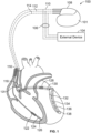
- an implantable medical device includes electrodes configured to be located in or about a heart.
- the electrodes include a bipolar electrode combination that define a bipolar sensing vector.
- the electrodes include a unipolar electrode combination that define a unipolar sensing vector.
- the IMD includes sensing circuitry configured to define a first sensing channel coupled to the bipolar electrode combination and a second sensing channel coupled to the unipolar electrode combination.
- the one or more processors may be further configured to compare the SID and the amplitude COI to corresponding SID and COI criteria and based on the comparisons.
- the one or more processors may designate the current series of beats to be a PVT or MVT.
- the SID and COI criteria may include SID and COI thresholds, respectively.
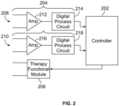
- the first sensing channel may include a first amplifier and a first digital processing circuit.
- the first amplifier may include input terminals that are coupled to the bipolar electrode combination.
- the second sensing channel may include a second amplifier and a second digital processing circuit.
- the second amplifier may include input terminals that are coupled to the unipolar electrode combination.
- the bipolar and unipolar electrode combinations may include at least one common electrode.
- the bipolar electrode combination may include first and second electrodes located within or proximate to one or more chambers of the heart.
- the unipolar electrode combination may include a third electrode located remote from the heart.
- the one or more processors may be configured to store the designation of the PVT or MVT.
- the IMD may further comprise a telemetry circuitry configured to downloaded the designation of the PVT or MVT, from the IMD, to an external device.
- a method identifies a sensed interval delta (SID) from cardiac activity (CA) signals collected over a first sensing channel coupled to a bipolar electrode combination and a second sensing channel coupled to a unipolar electrode combination for at least a portion of a series of beats.
- the SID represents a timing interval between i) a COI in the CA signals collected over the first sensing channel and ii) the same COI in the CA signals collected over the second sensing channel.
- the method also comprisesdesignating the series of beats to correspond to be a polymorphic ventricular tachycardia (PVT) or a monomorphic ventricular tachycardia (MVT) based on the SID.
- PVT polymorphic ventricular tachycardia
- MVT monomorphic ventricular tachycardia
- the method may comprise identifying an amplitude characteristic of interest (COI) from the CA signals collected over the second sensing channel associated with the bipolar sensing vector for at least a portion of the series of beats, the designating of the series of beats to be PVT or MVT based in part on the COI.
- COI amplitude characteristic of interest
- the COI may be an R-wave and the SID represents the timing interval between i) a R-wave in the CA signals collected over the first sensing channel and ii) the same R-wave in the CA signals collected over the second sensing channel.
- the method may compare the SID and the amplitude COI to corresponding SID and COI criteria and based on the comparisons, designating the current series of beats to be a PVT or MVT.
- the SID and COI criteria may include SID and COI thresholds, respectively.
- the method may further comprise designating the series of beats to be PVT when the SID and amplitude COI exceed the corresponding SID and COI thresholds.
- the SID and COI criteria may include SID and COI thresholds, respectively.
- the method may further comprise designating the series of beats to be MVT when the SID and amplitude COI do not exceed the corresponding SID and COI thresholds.
- the SID and COI criteria may include SID and COI thresholds, respectively.
- the method may further comprise designating a discrimination not possible condition when only one of the SID and amplitude COI exceed the corresponding SID and COI thresholds and another of the SID and amplitude COI do not exceed the corresponding SID and COI thresholds.
- the first and second sensing channels may utilize at least one common electrode.
- This disclosure proposes an IMD and method to track and evaluate the sensed events during a ventricular arrhythmia and stratify them between polymorphic or monomorphic event.
- the invention takes advantage of peak R-wave amplitudes and sensed interval delta in the device bipolar and unipolar signals, collected throughout the arrhythmia episode, from which the IMD or method can determine the therapy to deliver for the identified arrhythmia.
- Ventricular tachycardia shall mean a ventricular arrhythmia that continues to make the heartbeat regularly but goes so fast that the heart never gets a chance to fill with blood. There's not an opportunity to build up the pressure, so the blood stops flowing.
- characteristic of interest shall mean a characteristic of interest in a cardiac cycle or heartbeat that is manifest or otherwise apparent in the CA signals collected for the cardiac cycle or heartbeat.
- a COI may be a peak of a ventricular contract, also referred to as a peak of an R-wave.
- the phrase "same COI" shall mean a characteristic of interest in a single/common cardiac cycle that is manifest in CA signals measured over multiple sensing channels.
- the same COI may manifest itself or otherwise appear differently in first and second CA signals collected over first and second sensing channels.
- the COI may appear at a first point in time as a peak in the CA signals with certain amplitude.
- the CA signals leading upto and following the peak may have first increasing and decreasing slopes.
- circuitry may be implemented by a leadless IMD, a subcutaneous IMD and the like.
- the amplifier 212 may have input terminals connected to tip and ring electrodes located proximate to a distal end and/or intermediate segment of a subcutaneous lead connected to a subcutaneous IMD in a bipolar sensing configuration, while the amplifier 216 may have input terminals connected to the same or different tip or ring electrodes and a housing of the subcutaneous IMD.
- the amplifier 212 and digital processing circuit 214 may be implemented in a leadless IMD (to provide a bipolar sensing channel), while the amplifier 216 and digital processing circuit 218 may be implemented in a subcutaneous IMD (to provide a unipolar sensing channel).
- PVT polymorphic VT
- MVT monomorphic VT
- the methods and systems take advantage of i) variability criterion and/or sensed interval delta (SID) criterion that appear different within CA signals collected along different sensing vectors and utilizing different sensing polarities.
- the variability criterion represent variability within peak R-wave amplitudes.
- the SID criterion represent a sensed interval delta between a characteristic of interest in cardiac activity signals collected along primary (e.g., bipolar) and secondary (e.g., unipolar) sensing channels.
- the methods and systems classify VT events as polymorphic or monomorphic and determine a corresponding action or therapy to deliver for the identified type of VT.
- the system and method may take different actions depending upon the type of IMD.
- the IMD may represent a transvenous or subcutaneous IMD that is configured to treat MVT and PVT.
- the treatment may include one or more HV shocks, one or more MV shocks, ATP therapy and the like.
- the IMD may withhold treatment for a period of time and allow a MVT to self-terminate. If the MVT does not self-terminate, the IMD may then deliver one or more types of therapy.
- a PVT may warrant a HV shock, while a MVT may be treated with ATP, a MV shock and/or afforded a period of time to self-terminate.
- the IMD collects CA signals along primary and secondary sensing channels that utilize different sensing vectors and electrode polarity configurations.
- FIG 3 illustrates examples of CA signals (e.g., EGMs) collected along primary and second sensing channels for a PVT and MVT.
- CA signals e.g., EGMs
- methods and systems discriminate between an unstable ⁇ polymorphic and a stable ⁇ monomorphic VT done using one or both of an amplitude COI and/or an SID.
- panel 302 illustrates CA signals for a series of beats where the CA signals are collected along a sensing vector that utilizes a bipolar electrode configuration (e.g., two RV electrodes, one RV and one LV electrode, one RV electrode and two or more LV electrodes, two or more RV electrodes and one LV electrode, one or more RA electrodes and one or more RV electrodes, etc.).
- a bipolar electrode configuration e.g., two RV electrodes, one RV and one LV electrode, one RV electrode and two or more LV electrodes, two or more RV electrodes and one LV electrode, one or more RA electrodes and one or more RV
- the CA signals correspond to a PVT episode, in which each beat has a peak R-wave amplitude as denoted by the dots 310.
- Panel 304 illustrates CA signals for the same series of beats as in panel 302, but with the CA signals collected along a sensing vector that utilizes a unipolar electrode configuration (e.g., one or more RV electrodes and the CAN electrode, one or more LV electrodes and the CAN electrode, etc.).
- the CA signals include beats with R-wave peak amplitudes as denoted by the dots 312.
- Panel 306 illustrates CA signals for a series of beats where the CA signals are collected along a sensing vector that utilizes a bipolar electrode configuration.
- the CA signals correspond to an MVT episode, in which each beat has a peak R-wave amplitude as denoted by the dots 314.
- Panel 308 illustrates CA signals for the same series of beats as in panel 306, but with the CA signals collected along a sensing vector that utilizes a unipolar electrode configuration.
- the CA signals include beats with R-wave peak amplitudes as denoted by the dots 316.
- the one or more processors analyze the CA signals collected over one or more sensing channels.
- the CA signals may be collected over a bipolar sensing channel, a unipolar sensing channel or one or more other sensing channels.
- the one or more processors analyze the CA signals to determine whether VT or VF are indicated.
- Various arrhythmia discrimination algorithms may be used to analyze the CA signals.
- the analysis at 402 may be based on another type of signal other than a CA signal.
- the VT/VF may be detected based on heart sounds, impedance signals and the like.
- the one or more processors manage obtaining CA signals over the first and second sensing channels for a series of beats.
- the series of beats corresponds to the series of beats for which the VT/VF was determined at 402.
- the one or more processors may merely access segments of CA signals stored in memory in connection with the first and second sensing channels. All CA signals collected over the first sensing channel may be stored in a first first-in-first-out (FIFO) buffer and all CA signals collected over the second sensing channel may be stored in a second FIFO buffer. When the buffers are full, the oldest/first data written to the buffer is written over by the newest data.
- the obtaining operations at 404 and 406 may involve moving segments of CA signals from the first and second buffers to longer-term memory for storage and analysis as described herein.
- the obtaining operations at 404 and 406 may be performed in parallel with the VT/VF determining operation at 402.
- new CA signals may be sensed at 404 and 406, and analyzed at 402 to determine whether a VT/VF episode is present.
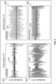
- Figure 5 illustrates an example of CA signals that are collected over a bipolar first sensing channel and a unipolar second sensing channel during a PVT and an MVT.
- Panel 502 corresponds to a PVT episode
- panel 504 corresponds to an MVT episode.
- CA signals 508 and 510 are collected over a bipolar first sensing channel and a unipolar second sensing channel, respectively.
- the CA signals 508 (over the bipolar sensing channel), during a PVT, exhibit a somewhat greater peak to peak amplitude difference (amplitude COI) (e.g., between successive peaks 512 and 514), as compared to the peak to peak (P-P) amplitude difference (e.g., between successive peaks 516 and 518) in the PVT CA signals 510 (over the unipolar sensing channel).
- amplitude COI peak to peak amplitude difference
- P-P peak to peak
- the P-P amplitude difference is much more notable, during an MVT.
- the CA signals 520 (over the bipolar sensing channel), exhibit a much greater peak to peak amplitude difference (e.g., between peaks 524 and 526), as compared to the P-P amplitude difference in the MVT CA signals 528 (over the unipolar sensing channel).
- the MVT CA signals 528 exhibit very little P-P amplitude difference between successive beats. Accordingly, the P-P amplitude difference in the CA signals sensed over the unipolar sensing channel yield a good indicator for MVT v. PVT.
- the CA signals 510, during a PVT, for the unipolar sensing channel exhibits a normalized P-P amplitude difference of 2 (+1 to -1), while the CA signals 528, during a MVT, for the unipolar sensing channel exhibits a normalized P-P amplitude difference of less than 0.5. More generally, it has been found that the P-P amplitude difference during an MVT is between 0 and 0.2, as measured over the unipolar sensing channel, while the P-P amplitude difference during a PVT is between 0.2 and 0.6, as measured over the bipolar sensing.
- the one or more processors calculate a relative feature of interest between the R-wave peaks.
- the one or more processors may calculate a maximum P-P amplitude difference in an amplitude of R-wave peaks between successive beats (e.g., R i -R i-1 ), where R i represents an amplitude of an R-wave peak for a current beat and R i-1 represents an amplitude of an R-wave peak for an immediately preceding beat.
- a subcutaneous, leadless or transvenous IMD, or implantable cardiac monitor may collect the CA signals over a bipolar first sensing channel, while a different subcutaneous, leadless or transvenous IMD, or implantable cardiac monitor collects the CA signals over a unipolar second sensing channel.
- One or more of the subcutaneous, leadless or transvenous IMD, or ICM may analyze the CA signals and designate the series of beats to be a PVT or MVT.
- One or more of the subcutaneous, leadless or transvenous IMD may deliver a PVT or MVT related therapy.
- the one or more processors compare the SID to an SID criterion. For example, the process determines whether a median SID is greater than a programmed SID threshold (e.g., ⁇ >SID threshold).
- the SID criterion may be programmed in various manners. For example, the SID may be between 10ms and 50ms in length, and more preferably between 15ms and 40ms.
- An SID threshold may be programmed to be 15ms or greater.
- the one or more processors compare the amplitude COI to an amplitude COI criterion.
- the amplitude COI may represent a maximum difference in an amplitude of R-wave peaks between successive beats (e.g., R i -R i-1 ), where R i represents an amplitude of an R-wave peak for a current beat and R i-1 represents an amplitude of an R-wave peak for an immediately preceding beat.
- the amplitude COI may represent a maximum difference in a median amplitude between first and second sets of beats (e.g., first set of 3-7 beats and second set of 3-7 beats).
- the amplitude COI criterion may be programmed in various manners.
- the amplitude COI may be an amplitude difference of between 0.1mV and 1.2mV between peak amplitudes of successive R-wave peaks. More preferably, the amplitude difference may be between 0.2mV and 0.6mV between peak amplitudes of successive R-wave peaks.
- the amplitude COI e.g., difference
- flow moves to 418.
- the amplitude COI is equal to or less than the COI threshold, flow moves to 420.
- the SID and amplitude COI have both satisfied the corresponding SID and COI criteria (e.g., thresholds) and accordingly, the one or more processors designate the series of beats to correspond to be a polymorphic ventricular tachycardia.
- the SID criterion is satisfied, but the COI criterion is not satisfied. Accordingly, the one or more processors determine that the process cannot discriminate between PVT or MVT for the series of beats. Accordingly, the series of beats is left unclassified or designated as a "discrimination not possible condition.”
- the one or more processors apply the amplitude COI criterion to determine whether the amplitude COI is greater than the COI threshold.
- the test at 422 may be the same as the test at 416.
- the COI threshold at 422 may differ from the COI threshold applied at 416.
- a COI threshold of 0.2mV may be programmed, whereas at 422 the COI threshold may be programmed to a higher lor lower amplitude difference (e.g., 0.3mV or 0.1mV).
- the one or more processors designate the series of beats to correspond to be a monomorphic ventricular tachycardia.
- the SID criterion is not satisfied, and the amplitude COI criterion is satisfied. Accordingly, the series of beats is left unclassified or designated as "discrimination not possible condition.”
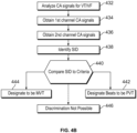
- Figure 4B illustrates a process for discriminating between PVT and MVT episodes based the SID from a series of beats, in accordance with embodiments herein.
- the operations of Figure 4B may be implemented in whole or in part by one or more processors of an IMD, an external device, a bedside monitor, a remote server or other computing device.
- the one or more processors analyze the CA signals collected over one or more sensing channels.
- the CA signals are collected over a bipolar sensing channel and over a unipolar sensing channel.
- the one or more processors analyze the CA signals to determine whether VT or VF are indicated.
- the one or more processors manage obtaining CA signals over the first and second sensing channels for a series of beats.
- the series of beats corresponds to the series of beats for which the VT/VF was determined at 432.
- the obtaining operations at 434 and 436 may include sensing/collection of new CA signals that are separate and occur after the CA signals analyzed at 432.
- the obtaining operations at 434 and 436 may be performed in parallel with the VT/VF determining operation at 432.
- the one or more processors identify a sensed interval delta (SID) from the CA signals for at least a portion of the series of beats.
- the one or more processors identify a COI in the CA signals collected over the first sensing channel and identify the same COI in the CA signals collected over the second sensing channel.
- the one or more processors calculate a time interval, as the SID, between i) the COI in the CA signals collected over the first sensing channel and ii) the same COI in the CA signals collected over the second sensing channel.
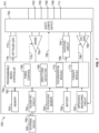
- the IMD 100 includes a programmable microcontroller 764 that controls various operations of the IMD 100, including cardiac monitoring and stimulation therapy.
- Microcontroller 764 includes a microprocessor (or equivalent control circuitry), RAM and/or ROM memory, logic and timing circuitry, state machine circuitry, and I/O circuitry.
- Microcontroller 764 is illustrated to include timing control circuitry 766 to control the timing of the stimulation pulses (e.g., pacing rate, atrio-ventricular (AV) delay, atrial interconduction (A-A) delay, or ventricular interconduction (V-V) delay, etc.).
- the timing control circuitry 766 may also be used for the timing of refractory periods, blanking intervals, noise detection windows, evoked response windows, alert periods, marker channel timing, and so on.
- Microcontroller 764 also has an arrhythmia detector 768 for detecting arrhythmia conditions and a discriminator module 770 to designate series of beats to correspond to be a polymorphic ventricular tachycardia (PVT) or a monomorphic ventricular tachycardia (MVT).
- the discriminator module 770 may be implemented by one or more processors that implement program instructions, along or in combination with firmware and/or circuitry to carry out the operations described herein.
- the discriminator module 770 is configured to collect cardiac activity (CA) signals over the first and second sensing channels for a series of beats.
- the CA signals are electrical signals indicative of changes in an electrical potential along a sensing vector between two or more electrodes.
- the CA signals are not impedance measurements.
- the data acquisition system 790 is configured to acquire intracardiac electrogram signals, convert the raw analog data into digital data, and store the digital data for later processing and/or telemetric transmission to an external device 104 (e.g., a programmer, local transceiver, or a diagnostic system analyzer).
- the data acquisition system 790 is controlled by a control signal 788 from the microcontroller 764.
- the units/modules/applications herein may execute a set of instructions that are stored in one or more storage elements, in order to process data.
- the storage elements may also store data or other information as desired or needed.
- the storage element may be in the form of an information source or a physical memory element within the modules/controllers herein.
- the set of instructions may include various commands that instruct the modules/applications herein to perform specific operations such as the methods and processes of the various embodiments of the subject matter described herein.
- the set of instructions may be in the form of a software program.
- the software may be in various forms such as system software or application software.
- the software may be in the form of a collection of separate programs or modules, a program module within a larger program or a portion of a program module.
- the software also may include modular programming in the form of object-oriented programming.
- the processing of input data by the processing machine may be in response to user commands, or in response to results of previous processing, or in response to a request made by another processing machine.
Landscapes
- Health & Medical Sciences (AREA)
- Cardiology (AREA)
- Life Sciences & Earth Sciences (AREA)
- Heart & Thoracic Surgery (AREA)
- General Health & Medical Sciences (AREA)
- Engineering & Computer Science (AREA)
- Animal Behavior & Ethology (AREA)
- Public Health (AREA)
- Veterinary Medicine (AREA)
- Biomedical Technology (AREA)
- Nuclear Medicine, Radiotherapy & Molecular Imaging (AREA)
- Radiology & Medical Imaging (AREA)
- Biophysics (AREA)
- Physiology (AREA)
- Vascular Medicine (AREA)
- Physics & Mathematics (AREA)
- Medical Informatics (AREA)
- Molecular Biology (AREA)
- Surgery (AREA)
- Pathology (AREA)
- Measurement And Recording Of Electrical Phenomena And Electrical Characteristics Of The Living Body (AREA)
- Electrotherapy Devices (AREA)
Claims (18)
- Implantierbare medizinische Vorrichtung, IMD, (100), die umfasst:Elektroden (101, 122, 124, 126, 132-138), die konfiguriert sind, um in einem Herzen oder um ein Herz herum angeordnet zu werden, wobei die Elektroden (101, 122, 124, 126, 132-138) eine bipolare Elektrodenkombination (122, 124, 126, 132-138) beinhalten, die einen bipolaren Erfassungsvektor definiert, wobei die Elektroden (101, 122, 124, 126, 132-138) eine unipolare Elektrodenkombination (101, 122, 124, 126, 132-138) beinhaltet, die einen unipolaren Erfassungsvektor definiert;einen Erfassungsschaltkreis (204, 780), der konfiguriert ist, um einen ersten Erfassungskanal (208) zu definieren, der mit der bipolaren Elektrodenkombination (122, 124, 126, 132-138) gekoppelt ist, und dazu konfiguriert ist, einen zweiten Erfassungskanal (210) zu definieren, der mit der unipolaren Elektrodenkombination (101, 122, 124, 126, 132-138) gekoppelt ist;einen Speicher (752), um Programmanweisungen zu speichern;einen oder mehrere Prozessoren (764), die konfiguriert sind, um die Programmanweisungen umzusetzen zum:Sammeln von Signalen einer Herzaktivität, CA, über den ersten und den zweiten Erfassungskanal (208, 210) für eine Reihe von Schlägen; undIdentifizieren eines erfassten Intervalls Delta, SID, anhand der CA-Signale für zumindest einen Teil der Reihe von Schlägen, wobei das SID ein Zeitintervall zwischen i) einem Charakteristikum von Interesse, COI, in den CA-Signalen, die über den ersten Erfassungskanal (208) gesammelt werden, und ii) dem gleichen COI in den CA-Signalen, die über den zweiten Erfassungskanal (210) gesammelt werden, darstellt, dadurch gekennzeichnet, dass der eine oder die mehreren Prozessoren (764) ferner konfiguriert sind, um die Programmanweisungen umzusetzen zum:
Bestimmen, dass die Reihe von Schlägen einer polymorphen ventrikulären Tachykardie, PVT, oder einer monomorphen ventrikulären Tachykardie, MVT, entspricht, basierend auf dem SID. - IMD nach Anspruch 1, wobei der eine oder die mehreren Prozessoren (764) ferner konfiguriert sind, um basierend darauf, ob die Reihe von Schlägen als PVT oder MVT ausgewiesen ist, eine PVT-bezogene Therapie oder eine MVT-bezogene Therapie zu verabreichen.
- IMD nach Anspruch 1 oder 2, wobei der eine oder die mehreren Prozessoren (764) ferner konfiguriert sind, um ein Charakteristikum von Interesse, COI, in Bezug auf eine Amplitude anhand der CA-Signale zu identifizieren, die über den zweiten Erfassungskanal (210) gesammelt werden, der dem unipolaren Erfassungsvektor zugeordnet ist, für zumindest einen Teil der Reihe von Schlägen, wobei die Reihe von Schlägen teilweise basierend auf dem COI als PVT oder MVT bestimmt wird.
- IMD nach Anspruch 3, wobei das COI eine R-Zacke ist und das SID das Zeitintervall zwischen i) einer R-Zacke in den CA-Signalen, die über den ersten Erfassungskanal (208) gesammelt werden, und ii) der gleichen R-Zacke in den CA-Signalen, die über den zweiten Erfassungskanal (210) gesammelt werden, darstellt.
- IMD nach Anspruch 3 oder 4, wobei der eine oder die mehreren Prozessoren (764) ferner konfiguriert sind, um das SID und den Amplituden-COI mit entsprechenden SID- und COI-Kriterien zu vergleichen und wobei der eine oder die mehreren Prozessoren (752) die aktuelle Reihe von Schlägen basierend auf den Vergleichen als PVT oder MVT bestimmen.
- IMD nach Anspruch 5, wobei die SID- und COI-Kriterien SID- bzw. COI-Schwellenwerte beinhalten und wobei der eine oder die mehreren Prozessoren (764) ferner zumindest zu einem konfiguriert sind aus:a) Bestimmen der Reihe von Schlägen als PVT, wenn SID und Amplituden-COI die entsprechenden SID- und COI-Schwellenwerte überschreiten;b) Bestimmen der Reihe von Schlägen als MVT, wenn SID und Amplituden-COI die entsprechenden SID- und COI-Schwellenwerte nicht überschreiten; oderc) Bestimmen eines Unterscheidung-nicht-möglich-Zustands, wenn nur eines des SID und des Amplituden-COI die entsprechenden SID- und COI-Schwellenwerte überschreitet und ein anderes von SID und Amplituden-COI die entsprechenden SID- und COI-Schwellenwerte nicht überschreitet.
- IMD nach einem der Ansprüche 1 bis 6, wobei der erste Erfassungskanal (208) einen ersten Verstärker (212) und eine erste digitale Verarbeitungsschaltung (214) beinhaltet, der erste Verstärker (212) Eingangsklemmen beinhaltet, die mit der bipolaren Elektrodenkombination (122, 124 124, 126, 132-138) gekoppelt sind, wobei der zweite Erfassungskanal (210) einen zweiten Verstärker (216) und eine zweite digitale Verarbeitungsschaltung (218) beinhaltet, wobei der zweite Verstärker (216) Eingangsklemmen, beinhaltet, die mit der unipolaren Elektrodenkombination (101, 122, 124, 126, 132-138) gekoppelt sind.
- IMD nach einem der Ansprüche 1 bis 7, wobei die bipolare und die unipolare Elektrodenkombination (101, 122, 124, 126, 132-138) zumindest eine gemeinsame Elektrode (122, 124, 126, 132-138) beinhalten.
- IMD nach einem der Ansprüche 1 bis 8, wobei die bipolare Elektrodenkombination (122, 124, 126, 132-138) erste und zweite Elektroden (122, 124, 126, 132-138) beinhaltet, die sich innerhalb oder in der Nähe einer oder mehrerer Kammern des Herzens befinden, und die unipolare Elektrodenkombination (101, 122, 124, 126, 132-138) eine dritte Elektrode (101) beinhaltet, die sich abseits des Herzens befindet.
- IMD nach einem der Ansprüche 1 bis 9, wobei der eine oder die mehreren Prozessoren (764) konfiguriert sind, um die Bestimmung der PVT oder MVT zu speichern, wobei die IMD (752) ferner eine Telemetrieschaltung (754) umfasst, die konfiguriert ist, um die Bestimmung der PVT oder MVT von der IMD (100) auf ein externes Gerät (104) herunterzuladen.
- Verfahren, das umfasst:
Identifizieren eines SID anhand von CA-Signalen, die über einen ersten Erfassungskanal (208), der mit einer bipolaren Elektrodenkombination (122, 124, 126, 132-138) gekoppelt ist, und einen zweiten Erfassungskanal (210), der mit einer unipolaren Elektrodenkombination (101, 122, 124, 126, 132-138) gekoppelt ist, gesammelt werden, für zumindest einen Teil einer Reihe von Schlägen durch den einen oder die mehreren Prozessoren des IMD nach Anspruch 1, wobei das SID ein Zeitintervall zwischen i) einem COI in den CA-Signalen, die über den ersten Erfassungskanal (208) gesammelt werden, und ii) dem gleichen SOI in den CA-Signalen, die über den zweiten Erfassungskanal (201) gesammelt werden, darstellt, gekennzeichnet durch:
Bestimmen durch den einen oder die mehreren Prozessoren, dass die Reihe von Schlägen einer PVT oder einer MVT entspricht, basierend auf dem SID. - Verfahren nach Anspruch 11, das ferner das Identifizieren eines Charakteristikums von Interesse, COI, in Bezug auf eine Amplitude anhand der CA-Signale, die über den zweiten Erfassungskanal (210) gesammelt werden, der dem bipolaren Erfassungsvektor zugeordnet ist, für zumindest einen Teil der Reihe von Schlägen, durch den einen oder die mehreren Prozessoren umfasst, wobei die Reihe von Schlägen teilweise basierend auf dem COI als PVT oder MVT bestimmt wird.
- Verfahren nach Anspruch 12, wobei das COI eine R-Zacke ist und das SID das Zeitintervall zwischen i) einer R-Zacke in den CA-Signalen, die über den ersten Erfassungskanal gesammelt werden, und ii) der gleichen R-Zacke in den CA-Signalen, die über den zweiten Erfassungskanal gesammelt werden, darstellt.
- Verfahren nach Anspruch 12 oder 13, das ferner das Vergleichen des SID und des Amplituden-COI mit entsprechenden SID- und COI-Kriterien durch den einen oder die mehreren Prozessoren und das Bestimmen, dass die aktuelle Reihe von Schlägen eine PVT oder MVT ist, basierend auf den Vergleichen durch den einen oder die mehreren Prozessoren umfasst.
- Verfahren nach Anspruch 14, wobei die SID- und COI-Kriterien SID- bzw. COI-Schwellenwerte beinhalten und wobei das Verfahren ferner das Bestimmen, dass die Reihe von Schlägen eine PVT ist, wenn das SID und das Amplituden-COI die entsprechenden SID- und COI-Schwellenwerte überschreiten, durch den einen oder die mehreren Prozessoren umfasst.
- Verfahren nach Anspruch 14 oder 15, wobei die SID- und COI-Kriterien SID- bzw. COI-Schwellenwerte beinhalten und wobei das Verfahren ferner das Bestimmen, dass die Reihe von Schlägen eine MVT ist, wenn das SID und das Amplituden-COI die entsprechenden SID- und COI-Schwellenwerte nicht überschreiten, durch den einen oder die mehreren Prozessoren umfasst.
- Verfahren nach einem der Ansprüche 14 bis 16, wobei die SID- und COI-Kriterien SID- bzw. COI-Schwellenwerte beinhalten und wobei das Verfahren ferner das Bestimmen eines Unterscheidung-nicht-möglich-Zustands durch den einen oder die mehreren Prozessoren umfasst, wenn nur eines des SID und des Amplituden-COI die entsprechenden SID- und COI-Schwellenwerte überschreitet und ein anderes von SID und Amplituden-COI die entsprechenden SID- und COI-Schwellenwerte nicht überschreitet.
- Verfahren nach einem der Ansprüche 11 bis 17, wobei der erste und der zweite Erfassungskanal (208, 210) zumindest eine gemeinsame Elektrode (122, 124, 126, 132-138) verwenden.
Applications Claiming Priority (2)
| Application Number | Priority Date | Filing Date | Title |
|---|---|---|---|
| US202163281754P | 2021-11-22 | 2021-11-22 | |
| US17/960,894 US20230158310A1 (en) | 2021-11-22 | 2022-10-06 | Method and device for ventricular tachycardia polymorphic\monomorphic discriminator |
Publications (2)
| Publication Number | Publication Date |
|---|---|
| EP4183445A1 EP4183445A1 (de) | 2023-05-24 |
| EP4183445B1 true EP4183445B1 (de) | 2025-04-09 |
Family
ID=83691337
Family Applications (1)
| Application Number | Title | Priority Date | Filing Date |
|---|---|---|---|
| EP22201004.3A Active EP4183445B1 (de) | 2021-11-22 | 2022-10-12 | Verfahren und vorrichtung für polymorphen/monomorphen diskriminator von ventrikulärer tachykardie |
Country Status (2)
| Country | Link |
|---|---|
| US (1) | US20230158310A1 (de) |
| EP (1) | EP4183445B1 (de) |
Family Cites Families (9)
| Publication number | Priority date | Publication date | Assignee | Title |
|---|---|---|---|---|
| US3983867A (en) * | 1975-09-29 | 1976-10-05 | Robert Case | Method and apparatus for providing hexaxial ecg display |
| US4686988A (en) * | 1984-10-19 | 1987-08-18 | Sholder Jason A | Pacemaker system and method for measuring and monitoring cardiac activity and for determining and maintaining capture |
| US5193535A (en) * | 1991-08-27 | 1993-03-16 | Medtronic, Inc. | Method and apparatus for discrimination of ventricular tachycardia from ventricular fibrillation and for treatment thereof |
| US5447519A (en) * | 1994-03-19 | 1995-09-05 | Medtronic, Inc. | Method and apparatus for discrimination of monomorphic and polymorphic arrhythmias and for treatment thereof |
| US7047067B2 (en) * | 2002-05-31 | 2006-05-16 | Uab Research Foundation | Apparatus, methods, and computer program products for evaluating a risk of cardiac arrhythmias from restitution properties |
| US7130677B2 (en) * | 2002-12-04 | 2006-10-31 | Medtronic, Inc. | Methods and apparatus for discriminating polymorphic tachyarrhythmias from monomorphic tachyarrhythmias facilitating detection of fibrillation |
| US8532762B2 (en) * | 2005-12-20 | 2013-09-10 | Cardiac Pacemakers, Inc. | Discriminating polymorphic and monomorphic cardiac rhythms using template generation |
| US9278226B2 (en) * | 2014-03-05 | 2016-03-08 | Medtronic, Inc. | Shock therapy for monomorphic detected ventricular tachycardia |
| CN108471976B (zh) * | 2016-01-11 | 2021-07-27 | 索林Crm联合股份公司 | 有源植入式医疗除颤设备 |
-
2022
- 2022-10-06 US US17/960,894 patent/US20230158310A1/en active Pending
- 2022-10-12 EP EP22201004.3A patent/EP4183445B1/de active Active
Also Published As
| Publication number | Publication date |
|---|---|
| EP4183445A1 (de) | 2023-05-24 |
| US20230158310A1 (en) | 2023-05-25 |
Similar Documents
| Publication | Publication Date | Title |
|---|---|---|
| EP3247266B1 (de) | Vorrichtung zur herzschlagerfassung während der vorlagenerzeugung in einer medizinischen vorrichtung mit doppelten messsensoren | |
| US8538524B2 (en) | Systems and methods for detecting far-field oversensing based on signals sensed by the proximal electrode of a multipolar LV lead | |
| US8694097B2 (en) | Multi-channel sensing methods in implantable cardiovertor defibrillators | |
| US11969599B2 (en) | Method and device utilizing far field signals to identify and treat under-detected arrhythmias | |
| US12161474B2 (en) | Methods, devices and systems for identifying false R-R intervals and false arrhythmia detections due to R-wave undersensing or intermittent AV conduction block | |
| EP3285857B1 (de) | Verfahren und medizinisches vorrichtung zur unterscheidung zwischen einer supraventrikulären tachykardie und einer ventrikulären tachykardie | |
| US9119545B2 (en) | Arrhythmia classification | |
| EP3492139B1 (de) | Vorrichtung zur verwaltung einer selbstterminierungszeit für ventriculäre arrhythmien | |
| US20200147395A1 (en) | Method and device for discrimination of left ventricular pseudo-fusion pacing | |
| EP3918984B1 (de) | Verfahren, vorrichtungen und systeme zur verbesserung der r-wellendetektion und der arrhytmiedetektionsgenauigkeit | |
| US20250302389A1 (en) | Methods and systems for determining whether r-wave detections should be classified as false due to t-wave oversensing (two) or p-wave oversensing (pwo) | |
| US8738120B2 (en) | Implantable medical device and method comprising means for detecting and classifying an arrhythmia | |
| US7149569B1 (en) | Apparatus and method for improved morphology discrimination in an implantable cardioverter defibrillator | |
| US7379771B2 (en) | Conduction based automatic therapy selection | |
| EP4183445B1 (de) | Verfahren und vorrichtung für polymorphen/monomorphen diskriminator von ventrikulärer tachykardie | |
| US7697983B1 (en) | Implantable cardiac device and method of optimizing storage of electrophysiological data | |
| US11648404B2 (en) | Method and device for designating left ventricular pacing based on pre-LV and post-LV pacing cardiac activity signals | |
| US20230293085A1 (en) | Methods and apparatuses to detect tachycardias and selectively reject tachycardia detections | |
| US12564348B2 (en) | Device and method for detecting ventricular arrhythmias based on duty cycle characteristics |
Legal Events
| Date | Code | Title | Description |
|---|---|---|---|
| PUAI | Public reference made under article 153(3) epc to a published international application that has entered the european phase |
Free format text: ORIGINAL CODE: 0009012 |
|
| STAA | Information on the status of an ep patent application or granted ep patent |
Free format text: STATUS: THE APPLICATION HAS BEEN PUBLISHED |
|
| AK | Designated contracting states |
Kind code of ref document: A1 Designated state(s): AL AT BE BG CH CY CZ DE DK EE ES FI FR GB GR HR HU IE IS IT LI LT LU LV MC ME MK MT NL NO PL PT RO RS SE SI SK SM TR |
|
| STAA | Information on the status of an ep patent application or granted ep patent |
Free format text: STATUS: REQUEST FOR EXAMINATION WAS MADE |
|
| 17P | Request for examination filed |
Effective date: 20230612 |
|
| RBV | Designated contracting states (corrected) |
Designated state(s): AL AT BE BG CH CY CZ DE DK EE ES FI FR GB GR HR HU IE IS IT LI LT LU LV MC ME MK MT NL NO PL PT RO RS SE SI SK SM TR |
|
| P01 | Opt-out of the competence of the unified patent court (upc) registered |
Effective date: 20230616 |
|
| GRAP | Despatch of communication of intention to grant a patent |
Free format text: ORIGINAL CODE: EPIDOSNIGR1 |
|
| STAA | Information on the status of an ep patent application or granted ep patent |
Free format text: STATUS: GRANT OF PATENT IS INTENDED |
|
| INTG | Intention to grant announced |
Effective date: 20250107 |
|
| GRAS | Grant fee paid |
Free format text: ORIGINAL CODE: EPIDOSNIGR3 |
|
| GRAA | (expected) grant |
Free format text: ORIGINAL CODE: 0009210 |
|
| STAA | Information on the status of an ep patent application or granted ep patent |
Free format text: STATUS: THE PATENT HAS BEEN GRANTED |
|
| AK | Designated contracting states |
Kind code of ref document: B1 Designated state(s): AL AT BE BG CH CY CZ DE DK EE ES FI FR GB GR HR HU IE IS IT LI LT LU LV MC ME MK MT NL NO PL PT RO RS SE SI SK SM TR |
|
| REG | Reference to a national code |
Ref country code: GB Ref legal event code: FG4D |
|
| REG | Reference to a national code |
Ref country code: CH Ref legal event code: EP |
|
| REG | Reference to a national code |
Ref country code: DE Ref legal event code: R096 Ref document number: 602022012842 Country of ref document: DE |
|
| REG | Reference to a national code |
Ref country code: IE Ref legal event code: FG4D |
|
| REG | Reference to a national code |
Ref country code: NL Ref legal event code: MP Effective date: 20250409 |
|
| PG25 | Lapsed in a contracting state [announced via postgrant information from national office to epo] |
Ref country code: NL Free format text: LAPSE BECAUSE OF FAILURE TO SUBMIT A TRANSLATION OF THE DESCRIPTION OR TO PAY THE FEE WITHIN THE PRESCRIBED TIME-LIMIT Effective date: 20250409 |
|
| REG | Reference to a national code |
Ref country code: AT Ref legal event code: MK05 Ref document number: 1783027 Country of ref document: AT Kind code of ref document: T Effective date: 20250409 |
|
| PG25 | Lapsed in a contracting state [announced via postgrant information from national office to epo] |
Ref country code: FI Free format text: LAPSE BECAUSE OF FAILURE TO SUBMIT A TRANSLATION OF THE DESCRIPTION OR TO PAY THE FEE WITHIN THE PRESCRIBED TIME-LIMIT Effective date: 20250409 Ref country code: ES Free format text: LAPSE BECAUSE OF FAILURE TO SUBMIT A TRANSLATION OF THE DESCRIPTION OR TO PAY THE FEE WITHIN THE PRESCRIBED TIME-LIMIT Effective date: 20250409 Ref country code: PT Free format text: LAPSE BECAUSE OF FAILURE TO SUBMIT A TRANSLATION OF THE DESCRIPTION OR TO PAY THE FEE WITHIN THE PRESCRIBED TIME-LIMIT Effective date: 20250811 |
|
| REG | Reference to a national code |
Ref country code: LT Ref legal event code: MG9D |
|
| PG25 | Lapsed in a contracting state [announced via postgrant information from national office to epo] |
Ref country code: NO Free format text: LAPSE BECAUSE OF FAILURE TO SUBMIT A TRANSLATION OF THE DESCRIPTION OR TO PAY THE FEE WITHIN THE PRESCRIBED TIME-LIMIT Effective date: 20250709 Ref country code: GR Free format text: LAPSE BECAUSE OF FAILURE TO SUBMIT A TRANSLATION OF THE DESCRIPTION OR TO PAY THE FEE WITHIN THE PRESCRIBED TIME-LIMIT Effective date: 20250710 |
|
| PG25 | Lapsed in a contracting state [announced via postgrant information from national office to epo] |
Ref country code: PL Free format text: LAPSE BECAUSE OF FAILURE TO SUBMIT A TRANSLATION OF THE DESCRIPTION OR TO PAY THE FEE WITHIN THE PRESCRIBED TIME-LIMIT Effective date: 20250409 |
|
| PG25 | Lapsed in a contracting state [announced via postgrant information from national office to epo] |
Ref country code: BG Free format text: LAPSE BECAUSE OF FAILURE TO SUBMIT A TRANSLATION OF THE DESCRIPTION OR TO PAY THE FEE WITHIN THE PRESCRIBED TIME-LIMIT Effective date: 20250409 |
|
| PG25 | Lapsed in a contracting state [announced via postgrant information from national office to epo] |
Ref country code: HR Free format text: LAPSE BECAUSE OF FAILURE TO SUBMIT A TRANSLATION OF THE DESCRIPTION OR TO PAY THE FEE WITHIN THE PRESCRIBED TIME-LIMIT Effective date: 20250409 |
|
| PG25 | Lapsed in a contracting state [announced via postgrant information from national office to epo] |
Ref country code: AT Free format text: LAPSE BECAUSE OF FAILURE TO SUBMIT A TRANSLATION OF THE DESCRIPTION OR TO PAY THE FEE WITHIN THE PRESCRIBED TIME-LIMIT Effective date: 20250409 |
|
| PGFP | Annual fee paid to national office [announced via postgrant information from national office to epo] |
Ref country code: FR Payment date: 20250912 Year of fee payment: 4 |
|
| PG25 | Lapsed in a contracting state [announced via postgrant information from national office to epo] |
Ref country code: RS Free format text: LAPSE BECAUSE OF FAILURE TO SUBMIT A TRANSLATION OF THE DESCRIPTION OR TO PAY THE FEE WITHIN THE PRESCRIBED TIME-LIMIT Effective date: 20250709 |
|
| PGFP | Annual fee paid to national office [announced via postgrant information from national office to epo] |
Ref country code: IE Payment date: 20250912 Year of fee payment: 4 |
|
| PG25 | Lapsed in a contracting state [announced via postgrant information from national office to epo] |
Ref country code: IS Free format text: LAPSE BECAUSE OF FAILURE TO SUBMIT A TRANSLATION OF THE DESCRIPTION OR TO PAY THE FEE WITHIN THE PRESCRIBED TIME-LIMIT Effective date: 20250809 |
|
| PG25 | Lapsed in a contracting state [announced via postgrant information from national office to epo] |
Ref country code: LV Free format text: LAPSE BECAUSE OF FAILURE TO SUBMIT A TRANSLATION OF THE DESCRIPTION OR TO PAY THE FEE WITHIN THE PRESCRIBED TIME-LIMIT Effective date: 20250409 |
|
| REG | Reference to a national code |
Ref country code: CH Ref legal event code: U11 Free format text: ST27 STATUS EVENT CODE: U-0-0-U10-U11 (AS PROVIDED BY THE NATIONAL OFFICE) Effective date: 20251101 |
|
| PGFP | Annual fee paid to national office [announced via postgrant information from national office to epo] |
Ref country code: DE Payment date: 20250912 Year of fee payment: 4 |
|
| REG | Reference to a national code |
Ref country code: DE Ref legal event code: R097 Ref document number: 602022012842 Country of ref document: DE |
|
| PG25 | Lapsed in a contracting state [announced via postgrant information from national office to epo] |
Ref country code: SM Free format text: LAPSE BECAUSE OF FAILURE TO SUBMIT A TRANSLATION OF THE DESCRIPTION OR TO PAY THE FEE WITHIN THE PRESCRIBED TIME-LIMIT Effective date: 20250409 Ref country code: DK Free format text: LAPSE BECAUSE OF FAILURE TO SUBMIT A TRANSLATION OF THE DESCRIPTION OR TO PAY THE FEE WITHIN THE PRESCRIBED TIME-LIMIT Effective date: 20250409 |
|
| PGFP | Annual fee paid to national office [announced via postgrant information from national office to epo] |
Ref country code: IT Payment date: 20251031 Year of fee payment: 4 |
|
| PGFP | Annual fee paid to national office [announced via postgrant information from national office to epo] |
Ref country code: CH Payment date: 20251101 Year of fee payment: 4 |
|
| PG25 | Lapsed in a contracting state [announced via postgrant information from national office to epo] |
Ref country code: CZ Free format text: LAPSE BECAUSE OF FAILURE TO SUBMIT A TRANSLATION OF THE DESCRIPTION OR TO PAY THE FEE WITHIN THE PRESCRIBED TIME-LIMIT Effective date: 20250409 |
|
| PG25 | Lapsed in a contracting state [announced via postgrant information from national office to epo] |
Ref country code: EE Free format text: LAPSE BECAUSE OF FAILURE TO SUBMIT A TRANSLATION OF THE DESCRIPTION OR TO PAY THE FEE WITHIN THE PRESCRIBED TIME-LIMIT Effective date: 20250409 |
|
| PG25 | Lapsed in a contracting state [announced via postgrant information from national office to epo] |
Ref country code: SK Free format text: LAPSE BECAUSE OF FAILURE TO SUBMIT A TRANSLATION OF THE DESCRIPTION OR TO PAY THE FEE WITHIN THE PRESCRIBED TIME-LIMIT Effective date: 20250409 |
|
| PLBE | No opposition filed within time limit |
Free format text: ORIGINAL CODE: 0009261 |
|
| STAA | Information on the status of an ep patent application or granted ep patent |
Free format text: STATUS: NO OPPOSITION FILED WITHIN TIME LIMIT |
|
| REG | Reference to a national code |
Ref country code: CH Ref legal event code: L10 Free format text: ST27 STATUS EVENT CODE: U-0-0-L10-L00 (AS PROVIDED BY THE NATIONAL OFFICE) Effective date: 20260218 |
|
| PG25 | Lapsed in a contracting state [announced via postgrant information from national office to epo] |
Ref country code: RO Free format text: LAPSE BECAUSE OF FAILURE TO SUBMIT A TRANSLATION OF THE DESCRIPTION OR TO PAY THE FEE WITHIN THE PRESCRIBED TIME-LIMIT Effective date: 20250409 |
|
| 26N | No opposition filed |
Effective date: 20260112 |