EP4516208A1 - Biomedizinischer sensor und zugehörige verfahren und herstellungsverfahren - Google Patents
Biomedizinischer sensor und zugehörige verfahren und herstellungsverfahren Download PDFInfo
- Publication number
- EP4516208A1 EP4516208A1 EP23194105.5A EP23194105A EP4516208A1 EP 4516208 A1 EP4516208 A1 EP 4516208A1 EP 23194105 A EP23194105 A EP 23194105A EP 4516208 A1 EP4516208 A1 EP 4516208A1
- Authority
- EP
- European Patent Office
- Prior art keywords
- sensor
- measurement
- membrane
- electrodes
- chamber
- Prior art date
- Legal status (The legal status is an assumption and is not a legal conclusion. Google has not performed a legal analysis and makes no representation as to the accuracy of the status listed.)
- Pending
Links
Images
Classifications
-
- A—HUMAN NECESSITIES
- A61—MEDICAL OR VETERINARY SCIENCE; HYGIENE
- A61B—DIAGNOSIS; SURGERY; IDENTIFICATION
- A61B5/00—Measuring for diagnostic purposes; Identification of persons
- A61B5/48—Other medical applications
- A61B5/4869—Determining body composition
- A61B5/4875—Hydration status, fluid retention of the body
-
- A—HUMAN NECESSITIES
- A61—MEDICAL OR VETERINARY SCIENCE; HYGIENE
- A61B—DIAGNOSIS; SURGERY; IDENTIFICATION
- A61B5/00—Measuring for diagnostic purposes; Identification of persons
- A61B5/05—Detecting, measuring or recording for diagnosis by means of electric currents or magnetic fields; Measuring using microwaves or radio waves
- A61B5/053—Measuring electrical impedance or conductance of a portion of the body
-
- A—HUMAN NECESSITIES
- A61—MEDICAL OR VETERINARY SCIENCE; HYGIENE
- A61B—DIAGNOSIS; SURGERY; IDENTIFICATION
- A61B5/00—Measuring for diagnostic purposes; Identification of persons
- A61B5/05—Detecting, measuring or recording for diagnosis by means of electric currents or magnetic fields; Measuring using microwaves or radio waves
- A61B5/053—Measuring electrical impedance or conductance of a portion of the body
- A61B5/0537—Measuring body composition by impedance, e.g. tissue hydration or fat content
-
- A—HUMAN NECESSITIES
- A61—MEDICAL OR VETERINARY SCIENCE; HYGIENE
- A61B—DIAGNOSIS; SURGERY; IDENTIFICATION
- A61B5/00—Measuring for diagnostic purposes; Identification of persons
- A61B5/145—Measuring characteristics of blood in vivo, e.g. gas concentration or pH-value ; Measuring characteristics of body fluids or tissues, e.g. interstitial fluid or cerebral tissue
- A61B5/14532—Measuring characteristics of blood in vivo, e.g. gas concentration or pH-value ; Measuring characteristics of body fluids or tissues, e.g. interstitial fluid or cerebral tissue for measuring glucose, e.g. by tissue impedance measurement
-
- A—HUMAN NECESSITIES
- A61—MEDICAL OR VETERINARY SCIENCE; HYGIENE
- A61B—DIAGNOSIS; SURGERY; IDENTIFICATION
- A61B5/00—Measuring for diagnostic purposes; Identification of persons
- A61B5/48—Other medical applications
- A61B5/4869—Determining body composition
- A61B5/4875—Hydration status, fluid retention of the body
- A61B5/4878—Evaluating oedema
Definitions
- the present disclosure relates to a biomedical sensor, which is designed for determining, in particular for (continuously) monitoring, an electrolyte status and/or a hydration status of a user/patient through respective electrical measurements.
- a specific use case of such a sensor and an efficient method for electrical determination of a water content and/or of an ionic content of an aqueous medium, respectively, in particular within human or within animal tissue, are also disclosed as well as a process for parallel wafer-level-fabrication of such biomedical sensors and a method for evaluating a sensor signal produced by such a sensor.
- a biomedical sensor is provided according to claim 1, which solves the aforementioned problem.
- the present invention thus proposes to employ an implantable biomedical sensor for accurately monitoring the electrolyte status and/or the hydration status of a patient.
- the invention proposes a sensor as introduced at the beginning, which, in addition, is characterized in that the sensor comprises a first measurement chamber, which is closed by and in communication with the ambient via a porous first membrane (which may be preferably a stiff membrane), which is permeable to ions (such as Na + , Cl - , Mg 2+ or Ca 2+ ).
- the first measurement chamber can communicate via the first membrane with an ambient surrounding the sensor.
- a first set of at least two measurement electrodes is arranged in the first measurement chamber and a second set of at least two measurement electrodes is arranged in the second measurement chamber (if present).
- this sensor can measure the user's hydration status and electrolyte status and transmit corresponding measurement data to a digital monitoring platform (accordingly the sensor may feature necessary wireless communication means for such communications).
- the sensor thus offers an efficient, reliable minimally invasive, and implantable solution to continuously monitor hydration and electrolyte status of a patient. This capability is enabled by the proposed choice of the measurement chamber design and the chosen membranes, as will be detailed below.
- the senor may be configured to perform a respective measurement of a respective electrical resistance of a respective liquid that is contained in the respective measurement chamber.
- the sensor can perform two independent electrical measurements, namely for determining the electrical resistance, in particular an impedance, of a first liquid contained in the first chamber (using a first set of electrodes arranged in the second chamber) and of a second liquid contained in the second chamber (using a second set of electrodes arranged in the second chamber).
- first membrane will also be permeable to water.
- both the first membrane and the second membrane may be permeable to water, with the possible distinction that the porous first membrane may be permeable to liquid water and ions, while the second membrane can be chosen such that it is only permeable to single water molecules (which will be the case for a PDMS membrane of 100 ⁇ m thickness, for example) but not for liquid water droplets.
- chamber closed by or delimited by a membrane may be understood herein as meaning that the respective membrane forms a boundary that delimits (and thereby defines) a volume of the respective measurement chamber. Via the membrane, the respective measurement chamber can thus be in touch with the ambient tissue and body fluids, as soon as the sensor is implanted into a human (or animal) body (e.g., subcutaneously).
- impermeable to ions may be interpreted technically as implying a sufficiently low penetration rate, such that the number of ions penetrating the membrane is so low that a measurement of a second electrical resistance using the second set of at least two measurement electrodes inside the second measurement chamber is not affected.
- the sensor can (indirectly) measure an electrolyte concentration in the tissue surrounding the sensor, when the sensor is introduced or implanted into the human body (of the user/patient). Thereby, the current electrolyte status of the patient/user can be determined with the sensor. This is because the higher the electrolyte concentration in the ambient, the more ions will diffuse into the first measurement chamber, resulting in an electrically measurable decrease of the electrical resistance/ increase of the electrical conductivity of the first liquid contained in the first measurement chamber. We note at this point that the volume of the first liquid may be effectively invariable, in particular when using a stiff first membrane.
- the sensor can (indirectly) measure a water content in the (surrounding) tissue (more precisely of the interstitial fluid (ISF) comprised in said tissue), when the sensor is introduced or implanted in the human body.
- ISF interstitial fluid
- the current electrolyte status of the patient/user can be determined with the sensor. This is because the higher the water content in the ambient (and thus the "hydration status"), the more water molecules will diffuse into the second measurement chamber via the second membrane, resulting in an increase in the volume of the second (aqueous) liquid contained in the second measurement chamber (note that the second membrane may expand, such that the volume of the second liquid is variable).
- the second membrane is, however, impermeable to ions, and therefore the number of ions will not change in the second measurement chamber, an infusion of water molecules will result in a decrease of the ion concentration (measured in number of ions / mL volume of the second liquid) and thus a measurable increase of the electrical resistance/ decrease of the electrical conductivity of the second liquid contained in the second measurement chamber.
- the invention therefore proposes a sensor as introduced at the beginning, which, in addition, is characterized in that the sensor comprises a measurement chamber, which is closed by and in communication with the ambient via a, preferably elastic, water-permeable membrane which is impermeable to ions (such as Na + , Cl - , Mg 2+ or Ca 2+ ). Moreover, a set of at least two measurement electrodes is arranged in the chamber. It is understood here that the measurement chamber just described may be the second measurement chamber described with correspondence to claim 1 and that, accordingly, the mentioned set of at least two electrodes may be said second set and the mentioned membrane may be said second membrane.
- the senor is preferably designed for implantation into the human body.
- the sensor may feature a biocompatible (outer) encapsulation.
- the sensor may be designed to be introduced (permanently or temporarily, for example in case of designing the sensor as part of a probe) into the human body.
- the sensor can be designed as a subcutaneous sensor and/or as part of a catheter designed for insertion into the human body.
- implant durations above 30 days are typically already considered “permanently”.
- the duration of implantation may be only a few minutes to a few hours.
- the senor is configured to measure a first electrical resistance (in particular a first electrical impedance, most preferably a first electrical impedance spectrum of said first liquid) with the first set of electrodes.
- a second electrical resistance in particular a second electrical impedance, most preferably a second electrical impedance spectrum of said second liquid.
- the first membrane can be made from a ceramic material, preferably from aluminum oxide (Al2O3).
- Al2O3 aluminum oxide
- Using a ceramic membrane as the first membrane is of advantage, because this safeguards that the first membrane shows a very low water absorption and practically no mechanical stress due to swelling in water, as it is often observed for polymer membranes, in particular membranes made from polyurethane (PU). Avoiding mechanical stress is important for achieving a reliable long-term bonding of the first membrane (e.g., to a spacer forming the first measurement chamber) and for maintaining a constant/invariable volume of the first measurement chamber (the volume should remain as invariable as possible for an accurate measurement).
- the first membrane can be chosen such that it offers nanoscale pores, preferably with a maximum pore size below 1 pm, most preferably with a maximum pore size below 200 nm.
- the first membrane can feature a thickness of at least 50 ⁇ m for providing sufficient stiffness. In such a case, it is most preferable, if the thickness of the first membrane is below 500 ⁇ m on the other hand, to enable a compact design.
- the mentioned electrodes of the sensor can comprise platin (Pt), either in the form of Pt or Pt/Ir, and/or Iridium, in particular IrOx.
- the second membrane can be made from a polymer material, preferably from polydimethylsiloxane (PDMS).
- PDMS polydimethylsiloxane
- the second membrane can feature a thickness of at least 100 pm, and preferably of at least 200 ⁇ m. In such cases, it will be preferably if the thickness is also below 500 pm, for enabling a compact design.
- the first measurement chamber is preferably filled with a first liquid (which may be in the form of a gel, for example).
- a first liquid which may be in the form of a gel, for example.
- said first liquid cannot diffuse through said first membrane out of the first measurement chamber. In other words, the first liquid will be trapped in the first chamber.
- the first membrane is permeable to a class of ions, wherein said class comprises at least one of the following ions: K+, Na+, Cl-, Mg2+, Fe2+, Fe3+, Cu2+, Ca2+.
- the sensor can be rendered capable of specifically and electrically measuring concentrations of ions belonging to said class of ions within the first measurement chamber.
- the first membrane can be impermeable to a class of large-sized objects, wherein said second class comprises at least one of the following objects: blood cells, proteins, for example proteins with a minimum diameter of x nm, bacteria.
- the advantage of this choice and design of the first membrane is that biofouling due to the presence of such objects inside the first measurement chamber can be prevented.
- a reliable long-term stable and selective (indirect) electrical measurement of the ion concentration of the interstitial fluid (ISF) surrounding the first measurement is achievable without interference from cells, proteins and other large-sized objects present in the ISF.
- ISF interstitial fluid
- the second measurement chamber may be filled with a, preferably aqueous, second liquid containing a defined and constant amount/number of ions.
- a number/concentration of ions present in the second liquid will be well-defined and/or constant over time. Accordingly, an osmotic pressure (dropping) via the second membrane can be well-defined.
- the sensor will then be capable of specifically and electrically measuring the amount of water contained in the second measurement chamber at a certain point in time, in particular after water has diffused into or out of the second measurement chamber through the second membrane, as explained previously. As this diffusion depends on the water content of the surrounding ISF, i.e., the hydration status of the user/patient, this approach allows indirect but accurate (in particular without any significant temporal delay) electrical measurement of the hydration status.
- the senor comprises a substrate and that the first and/or second set of electrodes comprise(s) at least two planar electrodes (respectively) deposited on said substrate.
- the electrodes are electrically connected to respective electrically conductive vias formed in the electrically insulating substrate.
- said planar electrodes may be structured by laser machining, most preferably by laser ablation, or by screen printing or by photolithography. All these techniques allow sufficient resolution for accurately defining the necessary electrode geometries.
- the substrate may be a ceramic substrate or a silicon substrate, for example.
- the structuring of the electrodes can be done by screen printing based on thick film technology, or through any photolithography method based on thin-film technology.
- the senor comprises a substrate (in particular said substrate with vias mentioned before) and the first and second measurement chambers are, in particular each, defined by a spacer attached to said substrate.
- a spacer attached to said substrate.
- the respective spacer can define sidewalls of the respective chamber.
- the respective spacer can provide a (preferably planar) surface to which the first membrane and/or the second membrane is/are bonded.
- the sensor may also comprise a controller configured to perform (i) a first electrical impedance measurement of said first liquid, using the first set of electrodes arranged inside the first measurement chamber and/or (ii) a second electrical impedance measurement of said second liquid using the second set of electrodes arranged inside the second measurement chamber. From these measurements, the controller may compute derived data indicating the current hydration status and/or electrolyte status.
- the controller can also be configured to transmit such data or measurement results, preferably wirelessly, to an external communication device (a computer, smartphone etc.). Using impedance measurement specifically allows more accurate evaluation of the hydration and/or electrolyte status, because a larger amount of measurement points will be available.
- the senor may then comprise the necessary hardware for performing such impedance measurements, such as AC current source with adjustable frequency.
- the sensor can thus comprise a current source configured to deliver an alternating current to said first and/or second set of electrodes, in particular such that an AC measurement of an electrical impedance can be performed by the sensor.
- the senor may comprise a controller (in particular said mentioned controller) configured to perform a variation, most preferably a continuous sweep, of a frequency of an alternating current applied to said first or second set of electrodes over a certain frequency range for performing impedance spectroscopy (EIS).
- the controller is configured to compute a real part and an imaginary part from such recorded impedance spectra.
- the sensor may comprise a voltmeter configured to perform a voltammetry measurement with the first and/or second set of electrodes and/or an amperemeter configured to perform an amperometry measurement with the first and/or second set of electrodes and/or a potentiometer configured to perform a potentiometry measurement with the first and/or second set of electrodes.
- the sensor can also comprise a controller (in particular said mentioned controller) configured to compute an ion concentration of a/the second liquid contained in the second measurement chamber and/or to compute a water content currently enclosed/comprised in the second measurement chamber (based on an assumed constant amount of ions contained in the second measurement chamber).
- a controller in particular said mentioned controller configured to compute an ion concentration of a/the second liquid contained in the second measurement chamber and/or to compute a water content currently enclosed/comprised in the second measurement chamber (based on an assumed constant amount of ions contained in the second measurement chamber).
- the (indirect) electrical measurement of the water content in the second measurement chamber can be valuable for determining the hydration status of the patient/user: the more water contained in the interstitial fluid (ISF) and the lower the ion content of the ISF, the higher the likelihood of water diffusing from the ISF into the second measurement chamber, due to the osmotic pressure dropping over the second membrane. Accordingly, a determined high water content/low ion concentration in the second measurement chamber will be indicative of a high hydration status of the patient/user.
- ISF interstitial fluid
- the first membrane can be so stiff that a liquid volume contained in the first measurement chamber, in particular a volume of said first liquid filling up the first chamber completely, is invariable within less than 1%, in particular even though ions and/or water can freely diffuse through said first membrane.
- a liquid volume contained in the second measurement chamber and delimited by the second membrane in particular a volume of said second liquid filling up the second chamber completely, can vary, in particular as a result of water diffusing through said second membrane.
- the first and/or the second set of electrodes comprises (respectively) at least four electrodes.
- the sensor may be configured for performing a 4-electrode-resistance measurement with the first and/or the second set of electrodes.
- the electrodes of the first and second set may be micro-electrodes with sub-mm dimensions.
- the senor features at least two separate first measurement chambers, wherein one of the two first chambers is closed by and separated from the ambient by a porous type A membrane, which is impermeable to a (in particular second) class of large-sized ions.
- said second class comprises at least one of the following ions: Ca2+, Mg 2+ .
- the other of the two first chambers may be closed by and separated from the ambient by a porous type B membrane, which is permeable to said, in particular second, class of large-sized ions.
- an ion concentration of a/the first class of ions can be electrically and specifically measured with the first chamber (2a) covered by the type A membrane and/or an ion concentration of the second class of ions can be electrically and specifically measured with the first chamber covered by the type B membrane. Accordingly, such a sensor design allows to collect even more information on the current electrolyte status and a specific measurement of certain classes of ions.
- the sensor can also feature a reference measurement chamber which is fully closed such that no ions and no water can penetrate from the ambient into the reference measurement chamber and wherein a third set of at least two measurement electrodes is arranged in the reference measurement chamber for performing electrical reference measurements.
- a third liquid with a defined electrical conductivity most preferably in the form of a hydrogel, can be contained in the reference measurement chamber.
- the advantage of such a reference measurement chamber is that the sensor can be configured to perform electrical reference measurements using the third set of electrodes. Based on the results of such a reference measurement, temperature drifts and other variations can be detected and compensated (e.g. by a controller of the sensor).
- the approach of the invention can also result in a specific use of a sensor as proposed herein (which may have features as claimed and/or as described herein).
- This use is characterized in that the sensor is used for monitoring the hydration status and/or the electrolyte status of a user/patient. Such monitoring may be performed continuously and/or repeatedly (e.g., in preset time intervals).
- the sensor may be implanted in or introduced into the user's body while/before the monitoring is performed.
- the sensor can be configured such that it performs the electrical measurements autonomously.
- a method for electrical determination of a water content and/or of an ionic content of an aqueous medium, respectively, in particular within human or animal tissue using a biomedical sensor (which may have features as claimed or described herein).
- the sensor should be in touch with the medium, in particular with said tissue.
- the method is distinguished in that an ionic concentration within a first measurement chamber of the sensor containing a first liquid is electrically measured by the sensor with a first set of electrodes in a first measurement for determining the ionic content in the medium / tissue. This may be done, in particular, by electrically measuring an electrical resistance and/or an electrical impedance of said first liquid, as described before. It is understood that during such measurements, ions may freely diffuse through the described first membrane into and out of said first measurement chamber.
- a water content or an ionic concentration within a second measurement chamber of the sensor containing a second liquid can be electrically measured by the sensor with a second set of electrodes in a second measurement (preferably independent of the first measurement) for determining the water content in the medium / tissue. This may be done, in particular, by electrically measuring an electrical resistance and/or an electrical impedance of said first liquid.
- ions and/or water may diffuse through a porous first membrane into the first measurement chamber during said first measurement and/or water molecules may diffuse through a second membrane into the second measurement chamber during said second measurement.
- the respective chamber can shielded / separated from the ambient, in particular from neighboring human or animal cells, by the respective membrane.
- the first measurement and/or the second measurement may be performed using an alternating current, respectively, which is provided by a current source of the sensor:
- the first measurement and/or the second measurement may thus include a variation, in particular a sweep, of a frequency of the respective alternating current, such that an impedance spectroscopy is performed, respectively.
- the method can also be designed and applied to allow autonomous monitoring of a hydration state and an electrolyte state of a patient.
- the sensor after having been introduced or implanted into the body of the patient, may transmit data of/related to said first and/or second measurement to an extracorporeal monitoring device (a tablet, smart phone or the like), which outputs a current (i.e. measured at this particular point in time) measurement value, in particular a measurement trend, related to the hydration status and the electrolyte status of the patient, based on the data transmitted by the sensor.
- the monitoring device can trigger the sensor, for example by transmitting an instruction to the sensor to perform a new first and second measurement. This instruction can of course depend on the data previously transmitted by the sensor to the monitoring device, i.e., the monitoring device can autonomously decide whether to trigger further measurements or not.
- the formation of the second liquid may be achieved by first depositing an ionic substance, for example a certain amount of an ionic salt, in each measurement chamber followed by dispensing of a liquid into the respective second measurement chamber.
- an ionic substance for example a certain amount of an ionic salt
- the final second liquid may be pre-fabricated and directly dispensed into the respective second measurement chamber.
- the process may further include a step of encapsulating of the dies with a bio-compatible soft encapsulation material for forming the individual biomedical sensors.
- said first membranes and said second membranes can each be left at least partially free from said encapsulation material. Thereby, a transfer of ions and/or of water molecules through the respective membrane will remain possible.
- the fabricated sensors can each show a planar design. Moreover, the sensors can be free of cables as all necessary electrical wiring can be integrated in or on the common substrate, in particular based on electrically conductive vias which are formed in the electrically insulating substrate. Such vias can connect the measurement electrodes on the upper side of the substrate with a current source and voltmeter arranged (in particular as separate electronic components) on the lower side of the substrate.
- the singulated dies can each be bonded to a respective lower microelectronic package, the package comprising a respective microelectronic circuit that is electrically connected to the electrodes formed on the top side of the substrate (in the respective chamber).
- This connection may be formed through electrically conductive vias which are formed in the electrically insulating substrate.
- the microelectronic circuit may implement an electronic controller of the sensor, with the controller configured to perform first and second electrical measurements in the chambers of the sensor to which the circuit belongs.
- an alternating current of variable frequency is employed by the sensor for measuring an electrical impedance spectrum of a liquid contained in a measurement chamber of said sensor.
- said chamber may be closed by and separated from the ambient by a water-permeable membrane, as described before.
- the impedance spectrum (in particular a real and an imaginary part of a measured impedance curve) may then be evaluated using a method of machine learning. This may be realized, in particular, by employing an artificial intelligence (AI) that performs the evaluation, which can be implemented in software and/or hardware.
- AI artificial intelligence
- ion concentrations of specific ions can be computed.
- the evaluation may be executed by a controller integrated in the sensor, in particular such that the sensor transmits data relating to the computed specific ion concentrations.
- the evaluation can also be executed by an external controller belonging to an extracorporeal monitoring device; in this case, said AI may be implemented by a software running on the monitoring device.
- the monitoring device may receive measurement data from said sensor, preferably wirelessly.
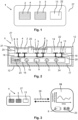
- Figure 1 shows a possible embodiment of a sensor 1 according to the invention, which features three separate measurement chambers 2, 3 and 13:
- the first measurement chamber 2 is closed by a ceramic first membrane 4 with nanometer-sized pores.
- ISF interstitial fluid
- the sensor 1 is implanted in human tissue subcutaneously, ions and water molecules present in the interstitial fluid (ISF) in close vicinity to the sensor 1 can freely diffuse from the ambient 27 through said first membrane 4 into a first liquid 6, which is enclosed in the first measurement chamber 2 by the first membrane 4.
- the first membrane 4 is stiff, the volume of the liquid 6 contained in the first measurement chamber 2 cannot change over time. This is also because the first liquid 6 is chosen such that it cannot diffuse through the first membrane 4 out of the first chamber 2.
- the concentration of ions present inside the first liquid 6 will quickly adapt to the corresponding ion concentration that is present in the surrounding ISF at a given point in time. This is because in case the ion concentration outside the first chamber 2 is higher than inside this chamber 2, ions will tend to diffuse into the first liquid 6 through the first membrane 4, thereby leveling the difference in ion concentrations.
- the design of the second measurement chamber 3 is similar to that of the first measurement chamber 2, however the second liquid 7 contained in the chamber 2 (which may be different from the first liquid 6) is closed by a second deformable polymer membrane 5, which is impermeable to ions but permeable to single water molecules.
- the second aqueous liquid 7 is chosen such that its ion concentration is well known. If the amount of water in the ISF increases due to a high hydration status, more water molecules will penetrate the second membrane 5 and as this membrane 5 is flexible, the volume of the second liquid 7 will increase, due to the water intake.
- the electrical conductivity of the second liquid 7 will drop, because the intake of water results in an effective decrease of the ion concentration inside the second measurement chamber 3 (note that all ions present in the second liquid 7 are trapped in the second chamber 3), because the number of ions inside this chamber 3 will not change / will be constant.
- the electrical conductivity and/or electrical resistance (which of course is technically equivalent) of the second liquid 7 in regular time intervals the hydration status in the surrounding ambient 27 can be indirectly determined / monitored by the sensor 1.
- Figure 2 shows, that the sensor 1 further comprises an internal non-conductive substrate 18, which forms the bottom of each of the three chambers 2, 3, and 13.
- a spacer 20 is bonded on the upper side of the substrate 18, thereby forming respective sidewalls 21 of each chamber 2/3/13.
- the membranes 4 and 5 of the first and second measurement chambers 2, 3 are left partially open, while the third measurement chamber 13, which serves as a reference measurement chamber, is fully closed by a cover 22, which is impermeable to both water and ions. In other words, there is no exchange between the ambient 27 and the third liquid 14 contained in said reference measurement chamber 13.
- the sensor design shown in Figure 2 could be fabricated with the wafer-level-process previously explained; in this case the size of the sensor 1 shown schematically in Figure 2 will roughly equal the size of die cut out of the carrier wafer 18 / main substrate 18 employed in the process.
- the microelectronic package 17 (which may be soldered to the vias 19 prior to or after singulation of the substrate 18 into single dies) comprises a controller 9, which operates a current source 10, a voltmeter 11 and an amperemeter 24 to perform various electrical measurements using the respective set of electrodes 8 present in each chamber 2, 3, 13. Note that these components 9,10,11,24 are all electrically connected to each other by electrical interconnects of the package 17. Through the vias 21, the controller can also electrically address the electrodes 8.
- the controller 9 can be programmed such that it electrically measures complex electrical impedance spectra of each liquid 6,7,14, respectively, using said components 9,10,11,24 and the electrodes 8. By considering the data resulting from electrical measurements performed in the reference measurement chamber 13, the controller 9 can compensate for temperature drifts. Note that the composition of the third liquid 14 and its volume do not change over time.
- the sensor 1 can transmit such measured data and/or data derived from such measurements by the controller 9 using a wireless communication module 23, which also forms part of said microelectronic package 17.
- the data are sent from the sensor 1 to a monitoring device 15, for example a tablet, which is located outside of the patient's body.
- This monitoring device 15 can then further evaluate the transmitted data, in particular based on an algorithm that implements an artificial intelligence, and can for example compute current trends of the electrolyte status and the hydration status of the patient. Such trends can then be visualized on a screen of the device 15 and can instruct the patient to an adequate behavior, e.g., drinking more water.
- an implantable biomedical sensor 1 which features a novel electrofluidic design based on dedicated measurement chambers 2, 3 which are sealed/closed up by respective membranes 4, 5, which are permeable to water molecules and, in the case of the first membrane 4, also to typical ions which are found in the human interstitial fluid (ISF).
- the sensor 1 can perform electrical measurements in the respective chamber 2, 3 and thereby collect data which allow conclusions to be drawn about the amount of water and ions present in the ISF surrounding the sensor 1.
- such a sensor 1 enables electrical monitoring of an electrolyte status and/or a hydration status of the patient wearing the implanted sensor 1 in his tissue.
Landscapes
- Health & Medical Sciences (AREA)
- Life Sciences & Earth Sciences (AREA)
- Physics & Mathematics (AREA)
- Medical Informatics (AREA)
- Surgery (AREA)
- Biophysics (AREA)
- Pathology (AREA)
- Engineering & Computer Science (AREA)
- Biomedical Technology (AREA)
- Heart & Thoracic Surgery (AREA)
- Veterinary Medicine (AREA)
- Molecular Biology (AREA)
- Public Health (AREA)
- Animal Behavior & Ethology (AREA)
- General Health & Medical Sciences (AREA)
- Nuclear Medicine, Radiotherapy & Molecular Imaging (AREA)
- Radiology & Medical Imaging (AREA)
- Optics & Photonics (AREA)
- Emergency Medicine (AREA)
- Measurement Of The Respiration, Hearing Ability, Form, And Blood Characteristics Of Living Organisms (AREA)
Priority Applications (4)
| Application Number | Priority Date | Filing Date | Title |
|---|---|---|---|
| EP26166299.3A EP4736756A2 (de) | 2023-08-29 | 2023-08-29 | Biomedizinischer sensor und zugehörige verfahren und herstellungsverfahren |
| EP23194105.5A EP4516208A1 (de) | 2023-08-29 | 2023-08-29 | Biomedizinischer sensor und zugehörige verfahren und herstellungsverfahren |
| PCT/EP2024/073988 WO2025045908A1 (en) | 2023-08-29 | 2024-08-28 | Biomedical sensor and associated methods and fabrication process |
| CN202480054743.9A CN121729174A (zh) | 2023-08-29 | 2024-08-28 | 生物医学传感器及相关方法和制造过程 |
Applications Claiming Priority (1)
| Application Number | Priority Date | Filing Date | Title |
|---|---|---|---|
| EP23194105.5A EP4516208A1 (de) | 2023-08-29 | 2023-08-29 | Biomedizinischer sensor und zugehörige verfahren und herstellungsverfahren |
Related Child Applications (1)
| Application Number | Title | Priority Date | Filing Date |
|---|---|---|---|
| EP26166299.3A Division EP4736756A2 (de) | 2023-08-29 | 2023-08-29 | Biomedizinischer sensor und zugehörige verfahren und herstellungsverfahren |
Publications (1)
| Publication Number | Publication Date |
|---|---|
| EP4516208A1 true EP4516208A1 (de) | 2025-03-05 |
Family
ID=87863424
Family Applications (2)
| Application Number | Title | Priority Date | Filing Date |
|---|---|---|---|
| EP23194105.5A Pending EP4516208A1 (de) | 2023-08-29 | 2023-08-29 | Biomedizinischer sensor und zugehörige verfahren und herstellungsverfahren |
| EP26166299.3A Pending EP4736756A2 (de) | 2023-08-29 | 2023-08-29 | Biomedizinischer sensor und zugehörige verfahren und herstellungsverfahren |
Family Applications After (1)
| Application Number | Title | Priority Date | Filing Date |
|---|---|---|---|
| EP26166299.3A Pending EP4736756A2 (de) | 2023-08-29 | 2023-08-29 | Biomedizinischer sensor und zugehörige verfahren und herstellungsverfahren |
Country Status (3)
| Country | Link |
|---|---|
| EP (2) | EP4516208A1 (de) |
| CN (1) | CN121729174A (de) |
| WO (1) | WO2025045908A1 (de) |
Citations (6)
| Publication number | Priority date | Publication date | Assignee | Title |
|---|---|---|---|---|
| US4822336A (en) * | 1988-03-04 | 1989-04-18 | Ditraglia John | Blood glucose level sensing |
| EP1631187B1 (de) * | 2003-06-10 | 2008-04-09 | Lifecare AS | In vivo sensormessung von osmotischen veränderungen |
| US20180263539A1 (en) * | 2015-09-28 | 2018-09-20 | The Regents Of The University Of California | Wearable sensor arrays for in-situ body fluid analysis |
| EP3634214B1 (de) * | 2017-06-07 | 2021-07-28 | Lifecare AS | Vorrichtung und verfahren zur messung des osmotischen drucks von interstitieller flüssigkeit |
| US20210315477A1 (en) * | 2020-04-14 | 2021-10-14 | Stichting Imec Nederland | System and Method for Monitoring Hydration Status of a Human Body |
| US11412959B2 (en) * | 2017-02-10 | 2022-08-16 | Epicore Biosystems, Inc. | EAB sensing devices with biofluid sample concentration |
Family Cites Families (1)
| Publication number | Priority date | Publication date | Assignee | Title |
|---|---|---|---|---|
| WO1997043634A1 (en) * | 1996-05-16 | 1997-11-20 | Sendx Medical, Inc. | Sensors with subminiature through holes, and method for fabricating such sensors |
-
2023
- 2023-08-29 EP EP23194105.5A patent/EP4516208A1/de active Pending
- 2023-08-29 EP EP26166299.3A patent/EP4736756A2/de active Pending
-
2024
- 2024-08-28 CN CN202480054743.9A patent/CN121729174A/zh active Pending
- 2024-08-28 WO PCT/EP2024/073988 patent/WO2025045908A1/en active Pending
Patent Citations (6)
| Publication number | Priority date | Publication date | Assignee | Title |
|---|---|---|---|---|
| US4822336A (en) * | 1988-03-04 | 1989-04-18 | Ditraglia John | Blood glucose level sensing |
| EP1631187B1 (de) * | 2003-06-10 | 2008-04-09 | Lifecare AS | In vivo sensormessung von osmotischen veränderungen |
| US20180263539A1 (en) * | 2015-09-28 | 2018-09-20 | The Regents Of The University Of California | Wearable sensor arrays for in-situ body fluid analysis |
| US11412959B2 (en) * | 2017-02-10 | 2022-08-16 | Epicore Biosystems, Inc. | EAB sensing devices with biofluid sample concentration |
| EP3634214B1 (de) * | 2017-06-07 | 2021-07-28 | Lifecare AS | Vorrichtung und verfahren zur messung des osmotischen drucks von interstitieller flüssigkeit |
| US20210315477A1 (en) * | 2020-04-14 | 2021-10-14 | Stichting Imec Nederland | System and Method for Monitoring Hydration Status of a Human Body |
Also Published As
| Publication number | Publication date |
|---|---|
| EP4736756A2 (de) | 2026-05-06 |
| WO2025045908A1 (en) | 2025-03-06 |
| CN121729174A (zh) | 2026-03-24 |
Similar Documents
| Publication | Publication Date | Title |
|---|---|---|
| JP7341583B6 (ja) | 微小針アレイベースの持続的分析物監視デバイスのための障害検出 | |
| EP4048152B1 (de) | System zur kontinuierlichen analytüberwachung mit einer mikronadelanordnung | |
| JP4365531B2 (ja) | 腫瘍の動的監視のための方法及びシステムとそれに関連する移植可能デバイス | |
| US8728289B2 (en) | Monolithic electrodes and pH transducers | |
| AU2002365064B2 (en) | Gateway platform for biological monitoring and delivery of therapeutic compounds | |
| US8965477B2 (en) | Analyte monitoring device and methods | |
| US9314631B2 (en) | Tongue sensors for monitoring multiple physiological parameters and tongue stimulation | |
| US20020042561A1 (en) | Implantable sensor and integrity tests therefor | |
| CA2550171A1 (en) | Sensor system as well as an arrangement and method for monitoring a constituent and in particular glucose in body tissue | |
| JP2013524198A (ja) | サンプリングプレート | |
| MX2013004852A (es) | Metodo y aparato para medir el potencial de oxidacion-reduccion. | |
| US20250235131A1 (en) | Analyte and environment sensors | |
| WO2019183529A1 (en) | Humidity-based sweat rate sensing devices | |
| EP4516208A1 (de) | Biomedizinischer sensor und zugehörige verfahren und herstellungsverfahren | |
| US20210001119A1 (en) | Implantable integrated sensor device | |
| US20220378335A1 (en) | Electrostimulation-free and biometrically encryptable noninvasive biochemical sensing device and method | |
| AU2012203630A1 (en) | Gateway platform for biological monitoring and delivery of therapeutic compounds | |
| Somps et al. | EFFECTS OF RAT SUBCUTANEOUS TISSUE ON A POLYMERIC | |
| Somps et al. | Microfabricated electrochemical sensors for chronic physiologic monitoring |
Legal Events
| Date | Code | Title | Description |
|---|---|---|---|
| PUAI | Public reference made under article 153(3) epc to a published international application that has entered the european phase |
Free format text: ORIGINAL CODE: 0009012 |
|
| STAA | Information on the status of an ep patent application or granted ep patent |
Free format text: STATUS: THE APPLICATION HAS BEEN PUBLISHED |
|
| AK | Designated contracting states |
Kind code of ref document: A1 Designated state(s): AL AT BE BG CH CY CZ DE DK EE ES FI FR GB GR HR HU IE IS IT LI LT LU LV MC ME MK MT NL NO PL PT RO RS SE SI SK SM TR |
|
| STAA | Information on the status of an ep patent application or granted ep patent |
Free format text: STATUS: REQUEST FOR EXAMINATION WAS MADE |
|
| 17P | Request for examination filed |
Effective date: 20250905 |
|
| STAA | Information on the status of an ep patent application or granted ep patent |
Free format text: STATUS: EXAMINATION IS IN PROGRESS |
|
| 17Q | First examination report despatched |
Effective date: 20251030 |