EP4513658A1 - Battery pack and battery cell interconnection component thereof - Google Patents
Battery pack and battery cell interconnection component thereof Download PDFInfo
- Publication number
- EP4513658A1 EP4513658A1 EP24196074.9A EP24196074A EP4513658A1 EP 4513658 A1 EP4513658 A1 EP 4513658A1 EP 24196074 A EP24196074 A EP 24196074A EP 4513658 A1 EP4513658 A1 EP 4513658A1
- Authority
- EP
- European Patent Office
- Prior art keywords
- metal strip
- battery cell
- battery
- metal
- section
- Prior art date
- Legal status (The legal status is an assumption and is not a legal conclusion. Google has not performed a legal analysis and makes no representation as to the accuracy of the status listed.)
- Pending
Links
Images






Classifications
-
- H—ELECTRICITY
- H01—ELECTRIC ELEMENTS
- H01M—PROCESSES OR MEANS, e.g. BATTERIES, FOR THE DIRECT CONVERSION OF CHEMICAL ENERGY INTO ELECTRICAL ENERGY
- H01M10/00—Secondary cells; Manufacture thereof
- H01M10/60—Heating or cooling; Temperature control
- H01M10/61—Types of temperature control
- H01M10/613—Cooling or keeping cold
-
- H—ELECTRICITY
- H01—ELECTRIC ELEMENTS
- H01M—PROCESSES OR MEANS, e.g. BATTERIES, FOR THE DIRECT CONVERSION OF CHEMICAL ENERGY INTO ELECTRICAL ENERGY
- H01M10/00—Secondary cells; Manufacture thereof
- H01M10/60—Heating or cooling; Temperature control
- H01M10/62—Heating or cooling; Temperature control specially adapted for specific applications
- H01M10/627—Stationary installations, e.g. power plant buffering or backup power supplies
-
- H—ELECTRICITY
- H01—ELECTRIC ELEMENTS
- H01M—PROCESSES OR MEANS, e.g. BATTERIES, FOR THE DIRECT CONVERSION OF CHEMICAL ENERGY INTO ELECTRICAL ENERGY
- H01M10/00—Secondary cells; Manufacture thereof
- H01M10/60—Heating or cooling; Temperature control
- H01M10/63—Control systems
-
- H—ELECTRICITY
- H01—ELECTRIC ELEMENTS
- H01M—PROCESSES OR MEANS, e.g. BATTERIES, FOR THE DIRECT CONVERSION OF CHEMICAL ENERGY INTO ELECTRICAL ENERGY
- H01M10/00—Secondary cells; Manufacture thereof
- H01M10/60—Heating or cooling; Temperature control
- H01M10/64—Heating or cooling; Temperature control characterised by the shape of the cells
- H01M10/647—Prismatic or flat cells, e.g. pouch cells
-
- H—ELECTRICITY
- H01—ELECTRIC ELEMENTS
- H01M—PROCESSES OR MEANS, e.g. BATTERIES, FOR THE DIRECT CONVERSION OF CHEMICAL ENERGY INTO ELECTRICAL ENERGY
- H01M10/00—Secondary cells; Manufacture thereof
- H01M10/60—Heating or cooling; Temperature control
- H01M10/65—Means for temperature control structurally associated with the cells
- H01M10/655—Solid structures for heat exchange or heat conduction
- H01M10/6551—Surfaces specially adapted for heat dissipation or radiation, e.g. fins or coatings
-
- H—ELECTRICITY
- H01—ELECTRIC ELEMENTS
- H01M—PROCESSES OR MEANS, e.g. BATTERIES, FOR THE DIRECT CONVERSION OF CHEMICAL ENERGY INTO ELECTRICAL ENERGY
- H01M10/00—Secondary cells; Manufacture thereof
- H01M10/60—Heating or cooling; Temperature control
- H01M10/65—Means for temperature control structurally associated with the cells
- H01M10/655—Solid structures for heat exchange or heat conduction
- H01M10/6554—Rods or plates
-
- H—ELECTRICITY
- H01—ELECTRIC ELEMENTS
- H01M—PROCESSES OR MEANS, e.g. BATTERIES, FOR THE DIRECT CONVERSION OF CHEMICAL ENERGY INTO ELECTRICAL ENERGY
- H01M10/00—Secondary cells; Manufacture thereof
- H01M10/60—Heating or cooling; Temperature control
- H01M10/65—Means for temperature control structurally associated with the cells
- H01M10/655—Solid structures for heat exchange or heat conduction
- H01M10/6556—Solid parts with flow channel passages or pipes for heat exchange
-
- H—ELECTRICITY
- H01—ELECTRIC ELEMENTS
- H01M—PROCESSES OR MEANS, e.g. BATTERIES, FOR THE DIRECT CONVERSION OF CHEMICAL ENERGY INTO ELECTRICAL ENERGY
- H01M10/00—Secondary cells; Manufacture thereof
- H01M10/60—Heating or cooling; Temperature control
- H01M10/65—Means for temperature control structurally associated with the cells
- H01M10/656—Means for temperature control structurally associated with the cells characterised by the type of heat-exchange fluid
- H01M10/6561—Gases
-
- H—ELECTRICITY
- H01—ELECTRIC ELEMENTS
- H01M—PROCESSES OR MEANS, e.g. BATTERIES, FOR THE DIRECT CONVERSION OF CHEMICAL ENERGY INTO ELECTRICAL ENERGY
- H01M10/00—Secondary cells; Manufacture thereof
- H01M10/60—Heating or cooling; Temperature control
- H01M10/65—Means for temperature control structurally associated with the cells
- H01M10/656—Means for temperature control structurally associated with the cells characterised by the type of heat-exchange fluid
- H01M10/6567—Liquids
- H01M10/6568—Liquids characterised by flow circuits, e.g. loops, located externally to the cells or cell casings
-
- H—ELECTRICITY
- H01—ELECTRIC ELEMENTS
- H01M—PROCESSES OR MEANS, e.g. BATTERIES, FOR THE DIRECT CONVERSION OF CHEMICAL ENERGY INTO ELECTRICAL ENERGY
- H01M50/00—Constructional details or processes of manufacture of the non-active parts of electrochemical cells other than fuel cells, e.g. hybrid cells
- H01M50/20—Mountings; Secondary casings or frames; Racks, modules or packs; Suspension devices; Shock absorbers; Transport or carrying devices; Holders
- H01M50/204—Racks, modules or packs for multiple batteries or multiple cells
-
- H—ELECTRICITY
- H01—ELECTRIC ELEMENTS
- H01M—PROCESSES OR MEANS, e.g. BATTERIES, FOR THE DIRECT CONVERSION OF CHEMICAL ENERGY INTO ELECTRICAL ENERGY
- H01M50/00—Constructional details or processes of manufacture of the non-active parts of electrochemical cells other than fuel cells, e.g. hybrid cells
- H01M50/20—Mountings; Secondary casings or frames; Racks, modules or packs; Suspension devices; Shock absorbers; Transport or carrying devices; Holders
- H01M50/204—Racks, modules or packs for multiple batteries or multiple cells
- H01M50/207—Racks, modules or packs for multiple batteries or multiple cells characterised by their shape
- H01M50/209—Racks, modules or packs for multiple batteries or multiple cells characterised by their shape adapted for prismatic or rectangular cells
-
- H—ELECTRICITY
- H01—ELECTRIC ELEMENTS
- H01M—PROCESSES OR MEANS, e.g. BATTERIES, FOR THE DIRECT CONVERSION OF CHEMICAL ENERGY INTO ELECTRICAL ENERGY
- H01M50/00—Constructional details or processes of manufacture of the non-active parts of electrochemical cells other than fuel cells, e.g. hybrid cells
- H01M50/20—Mountings; Secondary casings or frames; Racks, modules or packs; Suspension devices; Shock absorbers; Transport or carrying devices; Holders
- H01M50/251—Mountings; Secondary casings or frames; Racks, modules or packs; Suspension devices; Shock absorbers; Transport or carrying devices; Holders specially adapted for stationary devices, e.g. power plant buffering or backup power supplies
-
- H—ELECTRICITY
- H01—ELECTRIC ELEMENTS
- H01M—PROCESSES OR MEANS, e.g. BATTERIES, FOR THE DIRECT CONVERSION OF CHEMICAL ENERGY INTO ELECTRICAL ENERGY
- H01M50/00—Constructional details or processes of manufacture of the non-active parts of electrochemical cells other than fuel cells, e.g. hybrid cells
- H01M50/50—Current conducting connections for cells or batteries
- H01M50/502—Interconnectors for connecting terminals of adjacent batteries; Interconnectors for connecting cells outside a battery casing
- H01M50/503—Interconnectors for connecting terminals of adjacent batteries; Interconnectors for connecting cells outside a battery casing characterised by the shape of the interconnectors
-
- H—ELECTRICITY
- H01—ELECTRIC ELEMENTS
- H01M—PROCESSES OR MEANS, e.g. BATTERIES, FOR THE DIRECT CONVERSION OF CHEMICAL ENERGY INTO ELECTRICAL ENERGY
- H01M50/00—Constructional details or processes of manufacture of the non-active parts of electrochemical cells other than fuel cells, e.g. hybrid cells
- H01M50/50—Current conducting connections for cells or batteries
- H01M50/502—Interconnectors for connecting terminals of adjacent batteries; Interconnectors for connecting cells outside a battery casing
- H01M50/507—Interconnectors for connecting terminals of adjacent batteries; Interconnectors for connecting cells outside a battery casing comprising an arrangement of two or more busbars within a container structure, e.g. busbar modules
-
- H—ELECTRICITY
- H01—ELECTRIC ELEMENTS
- H01M—PROCESSES OR MEANS, e.g. BATTERIES, FOR THE DIRECT CONVERSION OF CHEMICAL ENERGY INTO ELECTRICAL ENERGY
- H01M50/00—Constructional details or processes of manufacture of the non-active parts of electrochemical cells other than fuel cells, e.g. hybrid cells
- H01M50/50—Current conducting connections for cells or batteries
- H01M50/502—Interconnectors for connecting terminals of adjacent batteries; Interconnectors for connecting cells outside a battery casing
- H01M50/521—Interconnectors for connecting terminals of adjacent batteries; Interconnectors for connecting cells outside a battery casing characterised by the material
- H01M50/522—Inorganic material
-
- Y—GENERAL TAGGING OF NEW TECHNOLOGICAL DEVELOPMENTS; GENERAL TAGGING OF CROSS-SECTIONAL TECHNOLOGIES SPANNING OVER SEVERAL SECTIONS OF THE IPC; TECHNICAL SUBJECTS COVERED BY FORMER USPC CROSS-REFERENCE ART COLLECTIONS [XRACs] AND DIGESTS
- Y02—TECHNOLOGIES OR APPLICATIONS FOR MITIGATION OR ADAPTATION AGAINST CLIMATE CHANGE
- Y02E—REDUCTION OF GREENHOUSE GAS [GHG] EMISSIONS, RELATED TO ENERGY GENERATION, TRANSMISSION OR DISTRIBUTION
- Y02E60/00—Enabling technologies; Technologies with a potential or indirect contribution to GHG emissions mitigation
- Y02E60/10—Energy storage using batteries
Definitions
- the present disclosure relates to a battery pack and a battery cell interconnection component thereof.
- battery cells in a battery pack are connected by flat metal plates.
- the flat metal plates When the battery pack is in operation, in addition to the battery cells generating heat, the flat metal plates also generate heat as a result of electric current passing through the flat metal plates. The heated flat metal plates could drive the temperatures of the battery cells further up, which may cause safety concerns.
- one of the objects of the present disclosure is to provide an improved battery pack and an improved battery cell interconnection component to resolve the technical problems mentioned above.
- a battery cell interconnection component includes a multi-layer structure and two holders.
- the multi-layer structure includes a plurality of first metal strips in a stack arrangement. A gap is formed between any two adjacent first metal strips.
- the two holders fixedly clamp two ends of the multi-layer structure, respectively. Each of the two holders is configured to be electrically connected to an electrode of a battery cell.
- the two holders include a second metal strip bent to form a concavity. An end of each of the first metal strips is inserted into the concavity.
- the second metal strip has a greater thickness than that of each of the first metal strips.
- each of the first metal strips includes a first material.
- the second metal strip includes a second material.
- the second material has a greater hardness than that of the first material.
- each of the first metal strips includes a first planar section, a second planar section and a middle section.
- the first planar section and the second planar section are spaced apart from each other.
- the middle section is located between the first planar section and the second planar section, and the middle section is at a height different from the first planar section and the second planar section.
- the two holders clamp the first planar section and the second planar section, respectively.
- each of the first metal strips further includes a first inclined section and a second inclined section.
- the first inclined section is connected between the first planar section and the middle section.
- the second inclined section is connected between the second planar section and the middle section.
- the first metal strips are bent one by one at the first inclined section and the second inclined section, such that the gap is formed between the middle sections of any two adjacent first metal strips.
- the first metal strips include a third metal strip and a fourth metal strip adjacent to the third metal strip.
- the third metal strip includes a middle section.
- the fourth metal strip has a notch and a flange extending from an edge of the notch. The flange is bent towards the third metal strip and abuts against the middle section of the third metal strip.
- the first metal strips include a third metal strip and a fourth metal strip adjacent to the third metal strip.
- the third metal strip is underneath the fourth metal strip.
- Two ends of the third metal strip are stacked with two ends of the fourth metal strip, and the fourth metal strip has a greater length than that of the third metal strip.
- a battery pack includes a housing, a plurality of battery cells and a plurality of battery cell interconnection components.
- the battery cells are disposed in the housing and each include a positive electrode and a negative electrode.
- the battery cells are arranged in at least one row along a direction. In said direction, the positive electrodes of the battery cells in the same row are aligned with one another, and the negative electrodes of the battery cells in the same row are aligned with one another.
- Each of the battery cell interconnection components includes a multi-layer structure and two holders.
- the multi-layer structure includes a plurality of first metal strips in a stack arrangement. A gap is formed between any two adjacent first metal strips.
- the two holders fixedly clamp two ends of the multi-layer structure, respectively. One of the two holders is attached to the positive electrode of a first battery cell of the battery cells, and the other of the two holders is attached to the negative electrode of a second battery cell of the battery cells.
- the second battery cell is adjacent to the first battery cell.
- the housing has a first side opening and a second side opening.
- the first side opening and the second side opening are provided on opposite sides of the housing and face the battery cell interconnection components.
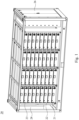
- Fig. 1 illustrates a schematic view of an energy storage cabinet 20 in accordance with an embodiment of the present disclosure.
- the energy storage cabinet 20 includes a frame 22 and one or more battery packs 21 disposed on the frame 22.
- the frame 22 is configured to support the battery packs 21.
- the frame 22 has one or more slots, and each of the slots is configured to accommodate one of the battery packs 21.
- the battery packs 21 are detachably disposed in the slots of the frame 22. In other words, the battery packs 21 can be inserted in the slots, and can be pulled out of the slots as needed (e.g., for the purpose of repair or maintenance).
- the battery packs 21 may be engaged with rail structures of the frame 22 (not depicted), such that the battery packs 21 can be slid into or out of the slots.
- the battery packs 21 are stacked along the vertical direction.
- the battery packs 21 can be divided into multiple floor assemblies 23. Battery packs 21 with the same elevation belong to the same floor assembly 23.
- the energy storage cabinet 20 includes nine floor assemblies 23, and one of which is identified by a dashed box.
- the battery packs 21 in the same floor assembly 23 are electrically connected in series, such that the voltages of the battery packs 21 in the same floor assembly 23 are summed up to produce a greater voltage.
- Each of the floor assemblies 23 has a common anode and a common cathode.
- the energy storage cabinet 20 further includes a junction device 26.
- the junction device 26 is disposed on the frame 22 and is positioned on one side of the energy storage cabinet 20.
- the junction device 26 is connected to the common anode and the common cathode (not depicted) of each of the floor assemblies 23.
- the junction device 26 may include a DC junction unit, an AC auxiliary unit, and one or more control units (or one or more switch units).
- Fig. 2 illustrates a schematic view of one of the battery packs 21 of the energy storage cabinet 20 shown in Fig. 1 .
- a lid of the battery pack 21 is removed to reveal the interior of the battery pack 21.
- the battery pack 21 includes a housing 29 and a plurality of battery cells 12 disposed in the housing 29.
- the battery cells 12 are, for example, lithium ion secondary batteries.
- the battery cells 12 may include prismatic cells shown in Fig. 2 .
- the battery cells 12 are arranged in at least one row along a direction D.
- the battery pack 21 includes forty-eight battery cells 12 arranged in four rows. Each of the rows has twelve battery cells 12.
- each of the battery cells 12 includes two electrodes 15 arranged side by side, one of which is a positive electrode 13 and the other is a negative electrode 14.
- the battery pack 21 further includes a plurality of first battery cell interconnection components 30, which may also be referred to as "bus bars".
- the first battery cell interconnection components 30 are disposed in the housing 29 and are configured to connect the battery cells 12 in series. Specifically, each of the first battery cell interconnection components 30 is electrically connected to the positive electrode 13 and the negative electrode 14 of two immediately adjacent battery cells 12 in the same row.
- the battery pack 21 further includes at least one second battery cell interconnection component 40.
- the second battery cell interconnection component 40 is disposed in the housing 29 and is electrically connected to the electrodes 15 of two battery cells 12 on adjacent rows.
- the electrodes 15 are provided on an upper surface of the battery cell 12.
- the first battery cell interconnection components 30 and the second battery cell interconnection component 40 are disposed over the battery cells 12 and are in contact with the electrodes 15 of the battery cells 12.
- the first battery cell interconnection components 30 and the second battery cell interconnection component 40 may include electrically conductive materials, such as copper or copper alloy.
- the first battery cell interconnection components 30 and the second battery cell interconnection component 40 can be affixed to the electrodes 15 of the battery cells 12 by means of laser welding, screwing, or other suitable techniques.
- the second battery cell interconnection component 40 is shorter in length than the first battery cell interconnection components 30.
- the housing 29 of the battery pack 21 has at least one first side opening 41 and at least one second side opening 42.
- the first side opening 41 and the second side opening 42 are provided on opposite sides of the housing 29 and are positioned to face the first battery cell interconnection components 30.
- the housing 29 includes two opposite sidewalls.
- the first side opening 41 and the second side opening 42 may be formed on the two opposite sidewalls, respectively.
- An upper edge of the first side opening 41 and an upper edge of the second side opening 42 are above the upper surfaces of the battery cells 12 (the upper surfaces of the battery cells 12 are where the electrodes 15 reside).
- the first side opening 41 and the second side opening 42 is configured to allow airflow (e.g., the cool air produced by the cooling device 28 shown in Fig.
- the first side opening 41, the second side opening 42 and the first battery cell interconnection component 30 can be provided at approximately the same height.
- airflow can enter the housing 29 through the first side opening 41, and then pass through the space above the battery cells 12 and the first battery cell interconnection components 30, and then leaves the housing 29 through the second side opening 42. Owing to the convention heat transfer mechanism, heat dissipation can be sped up.
- Fig. 3 illustrates a top view of the battery pack 21 shown in Fig. 2 , with the battery cell interconnection components being removed.
- the positive electrodes 13 of the battery cells 12 in the same row are aligned with one another, and the negative electrodes 14 of the battery cells 12 in the same row are aligned with one another.
- all of the battery cells 12 in the same row have their positive electrodes 13 arranged on the same side and their negative electrodes 14 arranged on the other same side.
- each of the first battery cell interconnection components 30 is attached to the positive electrode 13 of one of the battery cells 12 and the negative electrode 14 of another one of the battery cells 12. Consequently, each of the first battery cell interconnection components 30 is disposed at an angle to the direction D along which the battery cells 12 are arranged, and all the first battery cell interconnection components 30 in the same row tilt in the same direction.
- installation of the first battery cell interconnection components 30 can be automated, and the installation of the first battery cell interconnection components 30 can be completely more quickly, resulting in an improvement in productivity.
- a robotic arm can be deployed to place the first battery cell interconnection components 30 on the battery cells 12.
- the robotic arm can continuously place the first battery cell interconnection components 30 in the same row without having to rotate to change orientation.
- the arrangement of the battery cells 12 shown in Fig. 3 can help reduce errors and improve productivity when the battery pack 21 is manufactured.
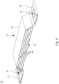
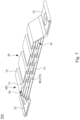
- Fig. 4 illustrates an enlarged view of one of the first battery cell interconnection components 30 of the battery pack 21 shown in Fig. 2 .
- the multi-layer structure 31 of the first battery cell interconnection component 30 includes a plurality of first metal strips 60 in a stack arrangement. A gap 35 is formed between any two immediately adjacent first metal strips 60. The gap 35 can allow airflow to pass through.
- the two holders 32 fixedly clamp two ends of the multi-layer structure 31, respectively, to combine the first metal strips 60. In some embodiments, the two holders 32 include folded metal pieces.
- each of the first metal strips 60 includes a middle section 65 located between the two holders 32.
- the middle sections 65 of any two immediately adjacent first metal strips 60 are spaced apart from each other to form the gap 35.
- Each of the holders 32 has an opening 33, which is, for example, a circular hole. The opening 33 can facilitate affixing the holders 32 to the corresponding electrodes 15 of the battery cells 12 by means of welding or screwing for electrical connection.
- each of the first metal strips 60 further includes a first planar section 61 and a second planar section 62.
- the first planar section 61 and the second planar section 62 are spaced apart from each other.
- the middle section 65 is located between the first planar section 61 and the second planar section 62, and the middle section 65 is at a height different from the first planar section 61 and the second planar section 62.
- the two holders 32 clamp the first planar sections 61 and the second planar sections 62 of the first metal strips 60, respectively.
- the ends of the first metal strips 60 are stacked at the first planar section 61, and then the stacked first planar sections 61 are received by the concavity 34 of one of the two holders 32.
- the other ends of the first metal strips 60 are stacked at the second planar section 62, and then the stacked second planar sections 62 are received by the concavity 34 of the other one of the two holders 32.
- the middle section 65 is substantially parallel to the first planar section 61 and the second planar section 62.
- each of the first metal strips 60 further includes a first inclined section 63 and a second inclined section 64.
- the first inclined section 63 is connected between the first planar section 61 and the middle section 65.
- the second inclined section 64 is connected between the second planar section 62 and the middle section 65.
- the first metal strips 60 are bent one by one at the first inclined section 63 and the second inclined section 64, such that one or more gaps 35 are formed between the middle sections 65 of the first metal strips 60.
- a method of manufacturing the first battery cell interconnection component 30 includes: (i) bending a plurality of flat metal strips to form a plurality of first metal strips 60 each having two inclined sections; (ii) stacking the first metal strips 60, and then using the two holders 32 to clamp the first planar sections 61 and the second planar sections 62 at two ends of the first metal strips 60; and (iii) applying ultrasonic welding to the two holders 32, the first planar sections 61 and the second planar sections 62. After the welding process is completed, the middle section 65 of each of the first metal strips 60 of the first battery cell interconnection component 30 are separated from each other, and one or more gaps 35 are formed therebetween.
- the bent portion 77 projects towards the metal strip M1 and abuts against the planar region 76 of the metal strip M1.
- the metal strip M1 is underneath the metal strip M2.
- the bent portion 77 of the metal strip M2 projects downward and abuts against the metal strip M1.
- the lowermost first metal strip 70 does not include the bent portion 77.
- Fig. 8 illustrates a schematic view of a first battery cell interconnection component 30B in accordance with another embodiment of the present disclosure.
- the first battery cell interconnection component 30B of the present embodiment includes a plurality of first metal strips 80.
- the first metal strips 80 differ from the first metal strips 60 described above in that at least one of the first metal strips 80 includes at least one flange 87.
- the flange 87 can provide support for the first metal strips 80.
- the first metal strips 70 include two immediately adjacent metal strips M1 and M2.
- the middle section 85 of the metal strip M2 has a notch 86 and the flange 87 extending from an edge of the notch 86.
- Fig. 9 illustrates a schematic side view of a first battery cell interconnection component 30C in accordance with another embodiment of the present disclosure.
- the first battery cell interconnection component 30C of the present embodiment includes a plurality of first metal strips 90.
- the first metal strips 90 differ from the first metal strips 60 described above in that at least two of the first metal strips 90 have unequal lengths.
- the middle section 65 of the longer first metal strip 90 rises and causes one or more gaps 35 to be formed between the first metal strips 90.
- the first metal strips 70 include two immediately adjacent metal strips M1 and M2. The metal strip M1 is underneath the metal strip M2.
- an outer edge of the first planar section 61 of the metal strip M1 can be aligned with an outer edge of the first planar section 61 of the metal strip M2, and an outer edge of the second planar section 62 of the metal strip M1 can be aligned with an outer edge of the second planar section 62 of the metal strip M2.
- the first inclined sections 63 of the metal strips M1 and M2 may be spaced apart from each other as shown in Fig. 9 , or may alternatively be in contact with each other.
- the second inclined sections 64 of the metal strips M1 and M2 may be spaced apart from each other as shown in Fig. 9 , or may alternatively be in contact with each other.
- all of the first metal strips 90 of the first battery cell interconnection component 30C have distinct lengths.
- the present disclosure provides a battery cell interconnection component for interconnecting multiple battery cells in a battery pack.
- the battery cell interconnection component includes a multi-layer structure.
- the multi-layer structure includes a plurality of metal strips in a stack arrangement, and a gap is formed between any two adjacent metal strips. With the multi-layer structure, overheating of the battery cell interconnection component itself can be prevented.
- the battery cell interconnection component can also act as a heatsink for the battery cells coupled thereto, so as to facilitate cooling of the battery cells.
Landscapes
- Chemical & Material Sciences (AREA)
- Chemical Kinetics & Catalysis (AREA)
- Electrochemistry (AREA)
- General Chemical & Material Sciences (AREA)
- Engineering & Computer Science (AREA)
- Manufacturing & Machinery (AREA)
- Inorganic Chemistry (AREA)
- Automation & Control Theory (AREA)
- Secondary Cells (AREA)
- Battery Mounting, Suspending (AREA)
- Connection Of Batteries Or Terminals (AREA)
Abstract
A battery cell interconnection component includes a multi-layer structure and two holders. The multi-layer structure includes a plurality of metal strips in a stack arrangement. A gap is formed between any two immediately adjacent metal strips. The two holders fixedly clamp two ends of the multi-layer structure, and each of the two holders is configured to be electrically connected to an electrode of a battery cell.
Description
- The present disclosure relates to a battery pack and a battery cell interconnection component thereof.
- Conventionally, battery cells in a battery pack are connected by flat metal plates. When the battery pack is in operation, in addition to the battery cells generating heat, the flat metal plates also generate heat as a result of electric current passing through the flat metal plates. The heated flat metal plates could drive the temperatures of the battery cells further up, which may cause safety concerns.
- In view of the foregoing, one of the objects of the present disclosure is to provide an improved battery pack and an improved battery cell interconnection component to resolve the technical problems mentioned above.
- To achieve the objective stated above, in accordance with an embodiment of the present disclosure, a battery cell interconnection component includes a multi-layer structure and two holders. The multi-layer structure includes a plurality of first metal strips in a stack arrangement. A gap is formed between any two adjacent first metal strips. The two holders fixedly clamp two ends of the multi-layer structure, respectively. Each of the two holders is configured to be electrically connected to an electrode of a battery cell.
- In one or more embodiments of the present disclosure, the two holders include a second metal strip bent to form a concavity. An end of each of the first metal strips is inserted into the concavity.
- In one or more embodiments of the present disclosure, the second metal strip has a greater thickness than that of each of the first metal strips.
- In one or more embodiments of the present disclosure, each of the first metal strips includes a first material. The second metal strip includes a second material. The second material has a greater hardness than that of the first material.
- In one or more embodiments of the present disclosure, each of the first metal strips includes a first planar section, a second planar section and a middle section. The first planar section and the second planar section are spaced apart from each other. The middle section is located between the first planar section and the second planar section, and the middle section is at a height different from the first planar section and the second planar section. The two holders clamp the first planar section and the second planar section, respectively.
- In one or more embodiments of the present disclosure, each of the first metal strips further includes a first inclined section and a second inclined section. The first inclined section is connected between the first planar section and the middle section. The second inclined section is connected between the second planar section and the middle section. The first metal strips are bent one by one at the first inclined section and the second inclined section, such that the gap is formed between the middle sections of any two adjacent first metal strips.
- In one or more embodiments of the present disclosure, the first metal strips include a third metal strip and a fourth metal strip adjacent to the third metal strip. The third metal strip includes a middle section. The fourth metal strip has a notch and a flange extending from an edge of the notch. The flange is bent towards the third metal strip and abuts against the middle section of the third metal strip.
- In one or more embodiments of the present disclosure, the first metal strips include a third metal strip and a fourth metal strip adjacent to the third metal strip. The third metal strip includes a planar region. The fourth metal strip includes a bent portion. The bent portion projects towards the third metal strip and abuts against the planar region of the third metal strip.
- In one or more embodiments of the present disclosure, the first metal strips include a third metal strip and a fourth metal strip adjacent to the third metal strip. The third metal strip is underneath the fourth metal strip. Two ends of the third metal strip are stacked with two ends of the fourth metal strip, and the fourth metal strip has a greater length than that of the third metal strip.
- In accordance with an embodiment of the present disclosure, a battery pack includes a housing, a plurality of battery cells and a plurality of battery cell interconnection components. The battery cells are disposed in the housing and each include a positive electrode and a negative electrode. The battery cells are arranged in at least one row along a direction. In said direction, the positive electrodes of the battery cells in the same row are aligned with one another, and the negative electrodes of the battery cells in the same row are aligned with one another. Each of the battery cell interconnection components includes a multi-layer structure and two holders. The multi-layer structure includes a plurality of first metal strips in a stack arrangement. A gap is formed between any two adjacent first metal strips. The two holders fixedly clamp two ends of the multi-layer structure, respectively. One of the two holders is attached to the positive electrode of a first battery cell of the battery cells, and the other of the two holders is attached to the negative electrode of a second battery cell of the battery cells. The second battery cell is adjacent to the first battery cell.
- In one or more embodiments of the present disclosure, the housing has a first side opening and a second side opening. The first side opening and the second side opening are provided on opposite sides of the housing and face the battery cell interconnection components.
- In sum, the present disclosure provides a battery cell interconnection component for interconnecting multiple battery cells in a battery pack. The battery cell interconnection component includes a multi-layer structure. The multi-layer structure includes a plurality of metal strips in a stack arrangement, and a gap is formed between any two adjacent metal strips. With the multi-layer structure, overheating of the battery cell interconnection component itself can be prevented. In addition, the battery cell interconnection component can also act as a heatsink for the battery cells coupled thereto, so as to facilitate cooling of the battery cells.
- To make the objectives, features, advantages, and embodiments of the present disclosure, including those mentioned above and others, more comprehensible, descriptions of the accompanying drawings are provided as follows.
-
Fig. 1 illustrates a schematic view of an energy storage cabinet in accordance with an embodiment of the present disclosure; -
Fig. 2 illustrates a schematic view of one of the battery packs of the energy storage cabinet shown inFig. 1 ; -
Fig. 3 illustrates a top view of the battery pack shown inFig. 2 , with the battery cell interconnection components being removed; -
Fig. 4 illustrates an enlarged view of one of the battery cell interconnection components of the battery pack shown inFig. 2 ; -
Fig. 5 illustrates a partially enlarged side view of the battery cell interconnection component shown inFig. 4 ; -
Fig. 6 illustrates an enlarged view of two of the battery cells and one of the battery cell interconnection components of the battery pack shown inFig. 2 ; -
Fig. 7 illustrates a schematic view of a battery cell interconnection component in accordance with another embodiment of the present disclosure; -
Fig. 8 illustrates a schematic view of a battery cell interconnection component in accordance with another embodiment of the present disclosure; and -
Fig. 9 illustrates a schematic side view of a battery cell interconnection component in accordance with another embodiment of the present disclosure. - For the completeness of the description of the present disclosure, reference is made to the accompanying drawings and the various embodiments described below. Various features in the drawings are not drawn to scale and are provided for illustration purposes only. To provide full understanding of the present disclosure, various practical details will be explained in the following descriptions. However, a person with an ordinary skill in relevant art should realize that the present disclosure can be implemented without one or more of the practical details. Therefore, the present disclosure is not to be limited by these details.
- Reference is made to
Fig. 1. Fig. 1 illustrates a schematic view of an energy storage cabinet 20 in accordance with an embodiment of the present disclosure. The energy storage cabinet 20 includes aframe 22 and one or more battery packs 21 disposed on theframe 22. Theframe 22 is configured to support the battery packs 21. Theframe 22 has one or more slots, and each of the slots is configured to accommodate one of the battery packs 21. The battery packs 21 are detachably disposed in the slots of theframe 22. In other words, the battery packs 21 can be inserted in the slots, and can be pulled out of the slots as needed (e.g., for the purpose of repair or maintenance). The battery packs 21 may be engaged with rail structures of the frame 22 (not depicted), such that the battery packs 21 can be slid into or out of the slots. - As shown in
Fig. 1 , the battery packs 21 are stacked along the vertical direction. The battery packs 21 can be divided intomultiple floor assemblies 23. Battery packs 21 with the same elevation belong to thesame floor assembly 23. In the illustrated embodiment, the energy storage cabinet 20 includes ninefloor assemblies 23, and one of which is identified by a dashed box. The battery packs 21 in thesame floor assembly 23 are electrically connected in series, such that the voltages of the battery packs 21 in thesame floor assembly 23 are summed up to produce a greater voltage. Each of thefloor assemblies 23 has a common anode and a common cathode. - As shown in
Fig. 1 , the energy storage cabinet 20 further includes ajunction device 26. Thejunction device 26 is disposed on theframe 22 and is positioned on one side of the energy storage cabinet 20. Thejunction device 26 is connected to the common anode and the common cathode (not depicted) of each of thefloor assemblies 23. Thejunction device 26 may include a DC junction unit, an AC auxiliary unit, and one or more control units (or one or more switch units). - As shown in
Fig. 1 , the energy storage cabinet 20 further includes acooling device 28. Thecooling device 28 is disposed on theframe 22 and is positioned on another side of the energy storage cabinet 20. Thecooling device 28 is configured to output a cool air to facilitate cooling of the battery packs 21. Thecooling device 28 is, for example, an air conditioner. In some embodiments, thejunction device 26 and thecooling device 28 are disposed on two opposite sides of the battery packs 21. - Reference is made to
Fig. 2. Fig. 2 illustrates a schematic view of one of the battery packs 21 of the energy storage cabinet 20 shown inFig. 1 . InFig. 2 , a lid of thebattery pack 21 is removed to reveal the interior of thebattery pack 21. Thebattery pack 21 includes ahousing 29 and a plurality ofbattery cells 12 disposed in thehousing 29. Thebattery cells 12 are, for example, lithium ion secondary batteries. Thebattery cells 12 may include prismatic cells shown inFig. 2 . Thebattery cells 12 are arranged in at least one row along a direction D. In the illustrated embodiment, thebattery pack 21 includes forty-eightbattery cells 12 arranged in four rows. Each of the rows has twelvebattery cells 12. - As shown in
Fig. 2 , each of thebattery cells 12 includes twoelectrodes 15 arranged side by side, one of which is apositive electrode 13 and the other is anegative electrode 14. Thebattery pack 21 further includes a plurality of first batterycell interconnection components 30, which may also be referred to as "bus bars". The first batterycell interconnection components 30 are disposed in thehousing 29 and are configured to connect thebattery cells 12 in series. Specifically, each of the first batterycell interconnection components 30 is electrically connected to thepositive electrode 13 and thenegative electrode 14 of two immediatelyadjacent battery cells 12 in the same row. In some embodiments, thebattery pack 21 further includes at least one second batterycell interconnection component 40. The second batterycell interconnection component 40 is disposed in thehousing 29 and is electrically connected to theelectrodes 15 of twobattery cells 12 on adjacent rows. - In the illustrated embodiment, the
electrodes 15 are provided on an upper surface of thebattery cell 12. The first batterycell interconnection components 30 and the second batterycell interconnection component 40 are disposed over thebattery cells 12 and are in contact with theelectrodes 15 of thebattery cells 12. The first batterycell interconnection components 30 and the second batterycell interconnection component 40 may include electrically conductive materials, such as copper or copper alloy. The first batterycell interconnection components 30 and the second batterycell interconnection component 40 can be affixed to theelectrodes 15 of thebattery cells 12 by means of laser welding, screwing, or other suitable techniques. In some embodiments, the second batterycell interconnection component 40 is shorter in length than the first batterycell interconnection components 30. - As shown in
Fig. 2 , each of the first batterycell interconnection components 30 includes amulti-layer structure 31 and twoholders 32. Themulti-layer structure 31 has one or more gaps. The twoholders 32 fixedly clamp two ends of themulti-layer structure 31. The twoholders 32 are electrically connected to theelectrodes 15 of twodifferent battery cells 12. Specifically, one of the twoholders 32 is attached to thepositive electrode 13 of one of thebattery cells 12, and the other one of the twoholders 32 is attached to thenegative electrode 14 of another one of thebattery cells 12. Themulti-layer structure 31 carries electric current flowing through thebattery cells 12 and additionally provides a heat removal function. Specifically, themulti-layer structure 31 has an enlarged surface area due to its multi-layer design, allowing heat to dissipate quickly. With themulti-layer structure 31, overheating of the first batterycell interconnection component 30 itself can be prevented. In addition, the first batterycell interconnection component 30 can also act as a heat sink for thebattery cells 12 coupled thereto, so as to facilitate cooling of thebattery cells 12. In some embodiments, the second batterycell interconnection component 40 may also include a multi-layer structure and two holders, the structures of which are similar to themulti-layer structure 31 and the twoholders 32 of the first batterycell interconnection component 30. - As shown in
Fig. 2 , thehousing 29 of thebattery pack 21 has at least onefirst side opening 41 and at least onesecond side opening 42. Thefirst side opening 41 and the second side opening 42 are provided on opposite sides of thehousing 29 and are positioned to face the first batterycell interconnection components 30. In some embodiments, thehousing 29 includes two opposite sidewalls. Thefirst side opening 41 and the second side opening 42 may be formed on the two opposite sidewalls, respectively. An upper edge of thefirst side opening 41 and an upper edge of the second side opening 42 are above the upper surfaces of the battery cells 12 (the upper surfaces of thebattery cells 12 are where theelectrodes 15 reside). Thefirst side opening 41 and the second side opening 42 is configured to allow airflow (e.g., the cool air produced by the coolingdevice 28 shown inFig. 1 ) to pass through. Thefirst side opening 41, the second side opening 42 and the first batterycell interconnection component 30 can be provided at approximately the same height. For example, airflow can enter thehousing 29 through thefirst side opening 41, and then pass through the space above thebattery cells 12 and the first batterycell interconnection components 30, and then leaves thehousing 29 through thesecond side opening 42. Owing to the convention heat transfer mechanism, heat dissipation can be sped up. - In some embodiments, the energy storage cabinet 20 has a fire protection function to cope with the situation where some or all of the
battery cells 12 fail and the temperature goes out of control or even causes fire. When the energy storage cabinet 20 detects overheating of at least onebattery pack 21, the energy storage cabinet 20 is configured to fill a cooling liquid (e.g., pure water) into thehousing 29 of the at least oneoverheating battery pack 21. In said situation, at least one of thefirst side opening 41 and the second side opening 42 can act as a discharge port for thebattery pack 21 to discharge excessive cooling liquid. As shown inFig. 2 , in some embodiments, a lower edge of at least one of thefirst side opening 41 and the second side opening 42 is at a position below theelectrodes 15 of thebattery cells 12. By this arrangement, when the cooling liquid is filled into thehousing 29, the highest level of the cooling liquid would be below theelectrodes 15 of thebattery cells 12, and thus the cooling liquid is prevented from contacting theelectrodes 15 of thebattery cells 12. - Reference is made to
Fig. 3. Fig. 3 illustrates a top view of thebattery pack 21 shown inFig. 2 , with the battery cell interconnection components being removed. As shown inFigs. 2 and3 , in the direction D along which thebattery cells 12 are arranged, thepositive electrodes 13 of thebattery cells 12 in the same row are aligned with one another, and thenegative electrodes 14 of thebattery cells 12 in the same row are aligned with one another. In other words, all of thebattery cells 12 in the same row have theirpositive electrodes 13 arranged on the same side and theirnegative electrodes 14 arranged on the other same side. As mentioned above, each of the first batterycell interconnection components 30 is attached to thepositive electrode 13 of one of thebattery cells 12 and thenegative electrode 14 of another one of thebattery cells 12. Consequently, each of the first batterycell interconnection components 30 is disposed at an angle to the direction D along which thebattery cells 12 are arranged, and all the first batterycell interconnection components 30 in the same row tilt in the same direction. By this arrangement, installation of the first batterycell interconnection components 30 can be automated, and the installation of the first batterycell interconnection components 30 can be completely more quickly, resulting in an improvement in productivity. For example, a robotic arm can be deployed to place the first batterycell interconnection components 30 on thebattery cells 12. Because thepositive electrodes 13 and thenegative electrodes 14 of thebattery cells 12 are in an aligned configuration as described above, the first batterycell interconnection components 30 in the same row have the same orientation. Therefore, the robotic arm can continuously place the first batterycell interconnection components 30 in the same row without having to rotate to change orientation. Compared to conventional battery packs in which the electrodes of the battery cells are interleaved, the arrangement of thebattery cells 12 shown inFig. 3 can help reduce errors and improve productivity when thebattery pack 21 is manufactured. - Reference is made to
Fig. 4. Fig. 4 illustrates an enlarged view of one of the first batterycell interconnection components 30 of thebattery pack 21 shown inFig. 2 . Themulti-layer structure 31 of the first batterycell interconnection component 30 includes a plurality of first metal strips 60 in a stack arrangement. Agap 35 is formed between any two immediately adjacent first metal strips 60. Thegap 35 can allow airflow to pass through. The twoholders 32 fixedly clamp two ends of themulti-layer structure 31, respectively, to combine the first metal strips 60. In some embodiments, the twoholders 32 include folded metal pieces. - As shown in
Fig. 4 , each of the first metal strips 60 includes amiddle section 65 located between the twoholders 32. Themiddle sections 65 of any two immediately adjacent first metal strips 60 are spaced apart from each other to form thegap 35. Each of theholders 32 has anopening 33, which is, for example, a circular hole. Theopening 33 can facilitate affixing theholders 32 to the correspondingelectrodes 15 of thebattery cells 12 by means of welding or screwing for electrical connection. - Reference is made to
Fig. 5. Fig. 5 illustrates a partially enlarged side view of the first batterycell interconnection component 30 shown inFig. 4 . In some embodiments, one or both of the twoholders 32 include a second metal strip bent to form aconcavity 34. On or both ends of each of the first metal strips 60 are inserted into theconcavity 34, and subsequently, ultrasonic welding or other suitable techniques can be applied to fixedly combine the first metal strips 60 and theholders 32. In some embodiments, the second metal strip has a greater thickness than that of each of the first metal strips 60. In some embodiments, each of the first metal strips 60 includes a first material, the second metal strip includes a second material, and the second material has a greater hardness than that of the first material. In some embodiments, the first metal strips 60 and the second metal strip include copper alloys of different hardness. - As shown in
Fig. 5 , each of the first metal strips 60 further includes a firstplanar section 61 and a secondplanar section 62. The firstplanar section 61 and the secondplanar section 62 are spaced apart from each other. Themiddle section 65 is located between the firstplanar section 61 and the secondplanar section 62, and themiddle section 65 is at a height different from the firstplanar section 61 and the secondplanar section 62. The twoholders 32 clamp the firstplanar sections 61 and the secondplanar sections 62 of the first metal strips 60, respectively. The ends of the first metal strips 60 are stacked at the firstplanar section 61, and then the stacked firstplanar sections 61 are received by theconcavity 34 of one of the twoholders 32. The other ends of the first metal strips 60 are stacked at the secondplanar section 62, and then the stacked secondplanar sections 62 are received by theconcavity 34 of the other one of the twoholders 32. Themiddle section 65 is substantially parallel to the firstplanar section 61 and the secondplanar section 62. - As shown in
Fig. 5 , each of the first metal strips 60 further includes a firstinclined section 63 and a secondinclined section 64. The firstinclined section 63 is connected between the firstplanar section 61 and themiddle section 65. The secondinclined section 64 is connected between the secondplanar section 62 and themiddle section 65. The first metal strips 60 are bent one by one at the firstinclined section 63 and the secondinclined section 64, such that one ormore gaps 35 are formed between themiddle sections 65 of the first metal strips 60. - In some embodiments, a method of manufacturing the first battery
cell interconnection component 30 includes: (i) bending a plurality of flat metal strips to form a plurality of first metal strips 60 each having two inclined sections; (ii) stacking the first metal strips 60, and then using the twoholders 32 to clamp the firstplanar sections 61 and the secondplanar sections 62 at two ends of the first metal strips 60; and (iii) applying ultrasonic welding to the twoholders 32, the firstplanar sections 61 and the secondplanar sections 62. After the welding process is completed, themiddle section 65 of each of the first metal strips 60 of the first batterycell interconnection component 30 are separated from each other, and one ormore gaps 35 are formed therebetween. - Reference is made to
Fig. 6. Fig. 6 illustrates an enlarged view of two of thebattery cells 12 and one of the first batterycell interconnection components 30 of thebattery pack 21 shown inFig. 2 . In some embodiments, themiddle section 65 of the lowermost first metal strip 60 (i.e., thefirst metal strip 60 closest to the battery cells 12) is at a position above theelectrodes 15 of thebattery cells 12 and the upper surfaces of thebattery cells 12. By this arrangement, anairflow passage 19 is formed between the lowermostfirst metal strip 60 and the upper surfaces of thebattery cells 12 to facilitate cooling of thebattery cells 12. - Reference is made to
Fig. 7. Fig. 7 illustrates a schematic view of a first batterycell interconnection component 30A in accordance with another embodiment of the present disclosure. The first batterycell interconnection component 30A of the present embodiment includes a plurality of first metal strips 70. The first metal strips 70 differ from the first metal strips 60 described above in that at least one of the first metal strips 70 includes at least onebent portion 77. Thebent portion 77 can provide support for the first metal strips 70. In some embodiments, the first metal strips 70 include two immediately adjacent metal strips M1 and M2. Themiddle section 75 of the metal strip M1 includes aplanar region 76. Themiddle section 75 of the metal strip M2 includes thebent portion 77. Thebent portion 77 projects towards the metal strip M1 and abuts against theplanar region 76 of the metal strip M1. In some embodiments, the metal strip M1 is underneath the metal strip M2. Thebent portion 77 of the metal strip M2 projects downward and abuts against the metal strip M1. In some embodiments, the lowermostfirst metal strip 70 does not include thebent portion 77. - Reference is made to
Fig. 8. Fig. 8 illustrates a schematic view of a first batterycell interconnection component 30B in accordance with another embodiment of the present disclosure. The first batterycell interconnection component 30B of the present embodiment includes a plurality of first metal strips 80. The first metal strips 80 differ from the first metal strips 60 described above in that at least one of the first metal strips 80 includes at least oneflange 87. Theflange 87 can provide support for the first metal strips 80. In some embodiments, the first metal strips 70 include two immediately adjacent metal strips M1 and M2. Themiddle section 85 of the metal strip M2 has anotch 86 and theflange 87 extending from an edge of thenotch 86. Theflange 87 is bent towards the metal strip M1 and abuts against themiddle section 85 of the metal strip M1. In some embodiments, the metal strip M1 is underneath the metal strip M2. Theflange 87 of the metal strip M2 is bent downward and abuts against the metal strip M1. In some embodiments, the lowermostfirst metal strip 80 does not include theflange 87. - Reference is made to
Fig. 9. Fig. 9 illustrates a schematic side view of a first batterycell interconnection component 30C in accordance with another embodiment of the present disclosure. The first batterycell interconnection component 30C of the present embodiment includes a plurality of first metal strips 90. The first metal strips 90 differ from the first metal strips 60 described above in that at least two of the first metal strips 90 have unequal lengths. When the two ends of the first metal strips 90 having unequal lengths are aligned, themiddle section 65 of the longerfirst metal strip 90 rises and causes one ormore gaps 35 to be formed between the first metal strips 90. In some embodiments, the first metal strips 70 include two immediately adjacent metal strips M1 and M2. The metal strip M1 is underneath the metal strip M2. Two ends of the metal strip M1 are stacked with two ends of the metal strip M2 (e.g., the firstplanar section 61 and the secondplanar section 62 of the metal strip M1 are stacked with the firstplanar section 61 and the secondplanar section 62 of the metal strip M2, respectively), and the metal strip M2 has a greater length than that of the metal strip M1. - As shown in
Fig. 9 , in some embodiments, an outer edge of the firstplanar section 61 of the metal strip M1 can be aligned with an outer edge of the firstplanar section 61 of the metal strip M2, and an outer edge of the secondplanar section 62 of the metal strip M1 can be aligned with an outer edge of the secondplanar section 62 of the metal strip M2. The firstinclined sections 63 of the metal strips M1 and M2 may be spaced apart from each other as shown inFig. 9 , or may alternatively be in contact with each other. Likewise, the secondinclined sections 64 of the metal strips M1 and M2 may be spaced apart from each other as shown inFig. 9 , or may alternatively be in contact with each other. In some embodiments, all of the first metal strips 90 of the first batterycell interconnection component 30C have distinct lengths. - In sum, the present disclosure provides a battery cell interconnection component for interconnecting multiple battery cells in a battery pack. The battery cell interconnection component includes a multi-layer structure. The multi-layer structure includes a plurality of metal strips in a stack arrangement, and a gap is formed between any two adjacent metal strips. With the multi-layer structure, overheating of the battery cell interconnection component itself can be prevented. In addition, the battery cell interconnection component can also act as a heatsink for the battery cells coupled thereto, so as to facilitate cooling of the battery cells.
Claims (11)
- A battery cell interconnection component (30, 30A, 30B, 30C), characterized by comprising:a multi-layer structure (31) comprising a plurality of first metal strips (60) in a stack arrangement, wherein a gap (35) is formed between any two adjacent ones of the first metal strips (60); andtwo holders (32) fixedly clamping two ends of the multi-layer structure (31), respectively, each of the two holders (32) being configured to be electrically connected to an electrode (15) of a battery cell (12).
- The battery cell interconnection component of claim 1, characterized in that the two holders (32) comprise a second metal strip, the second metal strip is bent to form a concavity (34), and an end of each of the first metal strips (60) is inserted into the concavity (34).
- The battery cell interconnection component of claim 2, characterized in that the second metal strip has a greater thickness than that of each of the first metal strips (60).
- The battery cell interconnection component of claim 2 or 3, characterized in that each of the first metal strips (60) comprises a first material, the second metal strip comprises a second material, and the second material has a greater hardness than that of the first material.
- The battery cell interconnection component of any preceding claim, characterized in that each of the first metal strips (60) comprises a first planar section (61), a second planar section (62) and a middle section (65), the first planar section (61) and the second planar section (62) are spaced apart from each other, the middle section (65) is located between the first planar section (61) and the second planar section (62), and the middle section (65) is at a height different from the first planar section (61) and the second planar section (62), wherein the two holders (32) clamp the first planar section (61) and the second planar section (62), respectively.
- The battery cell interconnection component of claim 5, characterized in that each of the first metal strips (60) further comprises a first inclined section (63) and a second inclined section (64), the first inclined section (63) is connected between the first planar section (61) and the middle section (65), the second inclined section (64) is connected between the second planar section (62) and the middle section (65), wherein the first metal strips (60) are bent one by one at the first inclined section (63) and the second inclined section (64), such that the gap (35) is formed between the middle sections (65) of any two adjacent ones of the first metal strips (60).
- The battery cell interconnection component of any preceding claim, characterized in that the first metal strips (60) comprise a third metal strip and a fourth metal strip adjacent to the third metal strip, the third metal strip comprises a middle section (65), the fourth metal strip has a notch (86) and a flange (87) extending from an edge of the notch (86), the flange (87) is bent towards the third metal strip and abuts against the middle section (65) of the third metal strip.
- The battery cell interconnection component of any of claims 1-6, characterized in that the first metal strips (60) comprise a third metal strip and a fourth metal strip adjacent to the third metal strip, the third metal strip comprises a planar region (76), the fourth metal strip comprises a bent portion (77), the bent portion (77) projects towards the third metal strip and abuts against the planar region (76) of the third metal strip.
- The battery cell interconnection component of any of claims 1-6, characterized in that the first metal strips (60) comprise a third metal strip and a fourth metal strip adjacent to the third metal strip, the third metal strip is underneath the fourth metal strip, wherein two ends of the third metal strip are stacked with two ends of the fourth metal strip, and the fourth metal strip has a greater length than that of the third metal strip.
- A battery pack (21), characterized by comprising:a housing (29);a plurality of battery cells (12) disposed in the housing (29) and each comprising a positive electrode (13) and a negative electrode (14), wherein the battery cells (12) are arranged in at least one row along a direction (D), in said direction (D), the positive electrodes (13) of the battery cells (12) in the same row are aligned with one another, and the negative electrodes (14) of the battery cells (12) in the same row are aligned with one another; anda plurality of the battery cell interconnection component (30, 30A, 30B, 30C) of any preceding claim, wherein one of the two holders is attached to the positive electrode of a first battery cell of the battery cells, and the other of the two holders is attached to the negative electrode of a second battery cell of the battery cells, the second battery cell is adjacent to the first battery cell.
- The battery pack of claim 10, characterized in that the housing (29) has a first side opening (41) and a second side opening (42), the first side opening (41) and the second side opening (42) are provided on opposite sides of the housing (29) and face the battery cell interconnection components (30, 30A, 30B, 30C).
Applications Claiming Priority (1)
| Application Number | Priority Date | Filing Date | Title |
|---|---|---|---|
| US202363534181P | 2023-08-23 | 2023-08-23 |
Publications (1)
| Publication Number | Publication Date |
|---|---|
| EP4513658A1 true EP4513658A1 (en) | 2025-02-26 |
Family
ID=92538402
Family Applications (3)
| Application Number | Title | Priority Date | Filing Date |
|---|---|---|---|
| EP24196074.9A Pending EP4513658A1 (en) | 2023-08-23 | 2024-08-23 | Battery pack and battery cell interconnection component thereof |
| EP24196071.5A Pending EP4513623A3 (en) | 2023-08-23 | 2024-08-23 | Energy storage cabinet and battery pack thereof |
| EP24196072.3A Active EP4513624B1 (en) | 2023-08-23 | 2024-08-23 | Energy storage cabinet |
Family Applications After (2)
| Application Number | Title | Priority Date | Filing Date |
|---|---|---|---|
| EP24196071.5A Pending EP4513623A3 (en) | 2023-08-23 | 2024-08-23 | Energy storage cabinet and battery pack thereof |
| EP24196072.3A Active EP4513624B1 (en) | 2023-08-23 | 2024-08-23 | Energy storage cabinet |
Country Status (4)
| Country | Link |
|---|---|
| US (3) | US20250070314A1 (en) |
| EP (3) | EP4513658A1 (en) |
| JP (3) | JP7829637B2 (en) |
| TW (3) | TWI890563B (en) |
Citations (4)
| Publication number | Priority date | Publication date | Assignee | Title |
|---|---|---|---|---|
| JP2009087761A (en) * | 2007-09-28 | 2009-04-23 | Toshiba Corp | Bus bar |
| DE102009033370A1 (en) * | 2009-07-16 | 2011-02-17 | Taller Gmbh | Busbar with compensation section |
| US9853435B1 (en) * | 2016-08-29 | 2017-12-26 | Ford Global Technologies, Llc | Busbar thermal management assembly and method |
| CN116581429A (en) * | 2023-07-12 | 2023-08-11 | 深圳海辰储能控制技术有限公司 | Energy storage modules and electrical equipment |
Family Cites Families (31)
| Publication number | Priority date | Publication date | Assignee | Title |
|---|---|---|---|---|
| JPH11238530A (en) * | 1998-02-23 | 1999-08-31 | Matsushita Electric Ind Co Ltd | Module battery cooling method and manufacturing method |
| JP2000310212A (en) * | 1999-04-23 | 2000-11-07 | Masuda Shoten:Kk | Clip nut |
| JP2005019134A (en) * | 2003-06-25 | 2005-01-20 | Shin Kobe Electric Mach Co Ltd | Lead-acid battery system |
| JP2008117708A (en) * | 2006-11-07 | 2008-05-22 | Toyota Motor Corp | Battery pack structure |
| JP5078463B2 (en) * | 2007-06-29 | 2012-11-21 | 三洋電機株式会社 | Power supply for vehicle |
| JP4875718B2 (en) * | 2009-01-21 | 2012-02-15 | 株式会社井上製作所 | Flexible conductor and method for producing flexible conductor |
| TWI466359B (en) * | 2010-08-23 | 2014-12-21 | Sumitomo Heavy Industries | Battery inspection device |
| JP6261975B2 (en) * | 2013-12-11 | 2018-01-17 | 株式会社東芝 | Heating element storage device |
| JP5874156B2 (en) * | 2014-01-31 | 2016-03-02 | 大阪フォーミング株式会社 | Clip nut |
| CN104836045A (en) * | 2014-02-10 | 2015-08-12 | 康舒科技股份有限公司 | Server power supply system and flexible connector thereof |
| US10269466B2 (en) * | 2016-05-17 | 2019-04-23 | Lear Corporation | High efficiency bus bar for use in conducting an alternating current and method for manufacturing same |
| JP2020057449A (en) * | 2017-01-31 | 2020-04-09 | 三洋電機株式会社 | Rack-type power supply |
| CN207517757U (en) * | 2017-11-21 | 2018-06-19 | 中航锂电(洛阳)有限公司 | Energy storage constant temperature cabinet and its cabinet |
| CN110120570B (en) * | 2018-02-07 | 2020-09-08 | 北京好风光储能技术有限公司 | Heat-equalizing bipolar battery stack |
| DE102018103706A1 (en) * | 2018-02-20 | 2019-08-22 | Dr. Ing. H.C. F. Porsche Aktiengesellschaft | Charging system with integrated coolant reservoir |
| JP7033730B2 (en) * | 2018-07-11 | 2022-03-11 | パナソニックIpマネジメント株式会社 | Cooling device, battery temperature control system and vehicle |
| CN209104249U (en) * | 2018-11-12 | 2019-07-12 | 宁德时代新能源科技股份有限公司 | battery module |
| CN110061162B (en) * | 2019-03-22 | 2023-04-07 | 中国电力科学研究院有限公司 | Energy storage battery cluster with heat dissipation and fire control function |
| KR102767147B1 (en) * | 2019-07-22 | 2025-02-11 | 주식회사 엘지에너지솔루션 | Energy storage system |
| JP2021077571A (en) * | 2019-11-12 | 2021-05-20 | 株式会社デンソー | Battery pack |
| CN111029496B (en) * | 2019-11-20 | 2022-04-22 | 江苏科技大学 | Energy storage battery heat dissipation support capable of efficiently dissipating heat |
| BR102020003216A2 (en) * | 2020-02-14 | 2021-08-31 | Melquisedec Francisquini | Sinusoidal tubular conductor bus |
| KR102650084B1 (en) * | 2020-03-04 | 2024-03-20 | 주식회사 엘지에너지솔루션 | Battery rack and energy storage system comprising the battery rack |
| US11895807B2 (en) * | 2020-05-28 | 2024-02-06 | Google Llc | Thermal management of battery units on data center racks |
| CN115692912A (en) * | 2021-07-30 | 2023-02-03 | 华为数字能源技术有限公司 | energy storage device |
| KR102856932B1 (en) * | 2022-02-08 | 2025-09-05 | 주식회사 엘지에너지솔루션 | Battery rack and energy storage system comprising the same |
| CN219419160U (en) * | 2022-11-09 | 2023-07-25 | 万物新能(深圳)科技有限公司 | Cooling and fire control integrated energy storage equipment |
| CN115775933B (en) * | 2022-12-27 | 2025-12-23 | 双一力(宁波)电池有限公司 | A type of air-cooled energy storage cabinet |
| CN116526001A (en) * | 2023-04-12 | 2023-08-01 | 深圳市广安电力设备有限公司 | Energy storage cabinet with temperature control function |
| CN116365103A (en) * | 2023-04-28 | 2023-06-30 | 杭州鹏成新能源科技有限公司 | A submerged liquid-cooled energy storage battery pack heat exchange device |
| CN118040199A (en) * | 2024-01-18 | 2024-05-14 | 广东奥丰新能源发展有限公司 | Immersed energy storage bag, energy storage cluster, energy storage compartment, energy storage system and working method thereof |
-
2024
- 2024-08-23 US US18/813,051 patent/US20250070314A1/en active Pending
- 2024-08-23 EP EP24196074.9A patent/EP4513658A1/en active Pending
- 2024-08-23 US US18/813,034 patent/US20250070297A1/en active Pending
- 2024-08-23 TW TW113131726A patent/TWI890563B/en active
- 2024-08-23 JP JP2024143474A patent/JP7829637B2/en active Active
- 2024-08-23 EP EP24196071.5A patent/EP4513623A3/en active Pending
- 2024-08-23 EP EP24196072.3A patent/EP4513624B1/en active Active
- 2024-08-23 JP JP2024141798A patent/JP7746492B2/en active Active
- 2024-08-23 US US18/813,049 patent/US20250070398A1/en active Pending
- 2024-08-23 JP JP2024141778A patent/JP2025031678A/en active Pending
- 2024-08-23 TW TW113131728A patent/TW202510400A/en unknown
- 2024-08-23 TW TW113131730A patent/TWI896305B/en active
Patent Citations (4)
| Publication number | Priority date | Publication date | Assignee | Title |
|---|---|---|---|---|
| JP2009087761A (en) * | 2007-09-28 | 2009-04-23 | Toshiba Corp | Bus bar |
| DE102009033370A1 (en) * | 2009-07-16 | 2011-02-17 | Taller Gmbh | Busbar with compensation section |
| US9853435B1 (en) * | 2016-08-29 | 2017-12-26 | Ford Global Technologies, Llc | Busbar thermal management assembly and method |
| CN116581429A (en) * | 2023-07-12 | 2023-08-11 | 深圳海辰储能控制技术有限公司 | Energy storage modules and electrical equipment |
Also Published As
| Publication number | Publication date |
|---|---|
| US20250070297A1 (en) | 2025-02-27 |
| US20250070314A1 (en) | 2025-02-27 |
| EP4513624A2 (en) | 2025-02-26 |
| TWI890563B (en) | 2025-07-11 |
| TWI896305B (en) | 2025-09-01 |
| JP2025031680A (en) | 2025-03-07 |
| JP2025031697A (en) | 2025-03-07 |
| JP7829637B2 (en) | 2026-03-13 |
| EP4513624A3 (en) | 2025-03-05 |
| US20250070398A1 (en) | 2025-02-27 |
| JP2025031678A (en) | 2025-03-07 |
| EP4513623A3 (en) | 2025-03-19 |
| JP7746492B2 (en) | 2025-09-30 |
| TW202510399A (en) | 2025-03-01 |
| TW202508865A (en) | 2025-03-01 |
| TW202510400A (en) | 2025-03-01 |
| EP4513624B1 (en) | 2025-12-17 |
| EP4513623A2 (en) | 2025-02-26 |
Similar Documents
| Publication | Publication Date | Title |
|---|---|---|
| EP2328201B1 (en) | Battery Pack | |
| EP3453060B1 (en) | Cooling arrangement for energy storage device | |
| US7393608B2 (en) | Rechargeable battery and battery module using the same | |
| JP5532278B2 (en) | Battery with multiple individual cells | |
| US7951483B2 (en) | Assembled battery with inner and outer frames | |
| EP2067194B1 (en) | Cell-module cartridge and mid-large battery module including the same | |
| US20120040226A1 (en) | Battery Module | |
| US20120100400A1 (en) | Instrument connection type unit pack combined cell cartridge | |
| US8669001B2 (en) | Device for combining and housing power storage cells | |
| US11901538B2 (en) | Sodium secondary battery module | |
| EP2515361A1 (en) | Battery unit | |
| JP2013038054A (en) | Battery module for high-voltage battery pack | |
| US20230216148A1 (en) | Structural busbar for battery | |
| KR20220094040A (en) | A battery module with multiple parallel battery cells | |
| JP7683895B2 (en) | Pouch-type battery cell with improved safety and battery module including the same | |
| CN103904261A (en) | Battery module | |
| KR20220151555A (en) | Laminated busbar for energy storage device | |
| EP4513658A1 (en) | Battery pack and battery cell interconnection component thereof | |
| JP2014022239A (en) | Battery pack | |
| CN103904282A (en) | Battery pack and battery module | |
| EP3471168B1 (en) | Battery module | |
| US20240322360A1 (en) | Battery pack | |
| US20200161626A1 (en) | Laminar Current Collector | |
| EP4614676A1 (en) | Battery pack | |
| EP4095997A1 (en) | Thermally efficient pouch cell architecture |
Legal Events
| Date | Code | Title | Description |
|---|---|---|---|
| PUAI | Public reference made under article 153(3) epc to a published international application that has entered the european phase |
Free format text: ORIGINAL CODE: 0009012 |
|
| STAA | Information on the status of an ep patent application or granted ep patent |
Free format text: STATUS: THE APPLICATION HAS BEEN PUBLISHED |
|
| AK | Designated contracting states |
Kind code of ref document: A1 Designated state(s): AL AT BE BG CH CY CZ DE DK EE ES FI FR GB GR HR HU IE IS IT LI LT LU LV MC ME MK MT NL NO PL PT RO RS SE SI SK SM TR |
|
| STAA | Information on the status of an ep patent application or granted ep patent |
Free format text: STATUS: REQUEST FOR EXAMINATION WAS MADE |
|
| 17P | Request for examination filed |
Effective date: 20250513 |