EP2067194B1 - Cell-module cartridge and mid-large battery module including the same - Google Patents
Cell-module cartridge and mid-large battery module including the same Download PDFInfo
- Publication number
- EP2067194B1 EP2067194B1 EP07808192.4A EP07808192A EP2067194B1 EP 2067194 B1 EP2067194 B1 EP 2067194B1 EP 07808192 A EP07808192 A EP 07808192A EP 2067194 B1 EP2067194 B1 EP 2067194B1
- Authority
- EP
- European Patent Office
- Prior art keywords
- cartridge body
- cartridge
- battery
- coupling
- cell
- Prior art date
- Legal status (The legal status is an assumption and is not a legal conclusion. Google has not performed a legal analysis and makes no representation as to the accuracy of the status listed.)
- Active
Links
- 238000010168 coupling process Methods 0.000 claims description 113
- 230000008878 coupling Effects 0.000 claims description 111
- 238000005859 coupling reaction Methods 0.000 claims description 111
- 238000009413 insulation Methods 0.000 claims description 37
- 239000002390 adhesive tape Substances 0.000 claims description 25
- 238000004519 manufacturing process Methods 0.000 claims description 23
- 239000002826 coolant Substances 0.000 claims description 12
- 238000001514 detection method Methods 0.000 claims description 11
- 239000000463 material Substances 0.000 claims description 9
- 229910052751 metal Inorganic materials 0.000 claims description 4
- 239000002184 metal Substances 0.000 claims description 4
- 239000011347 resin Substances 0.000 claims description 3
- 229920005989 resin Polymers 0.000 claims description 3
- 238000007599 discharging Methods 0.000 claims description 2
- 238000000034 method Methods 0.000 description 16
- 230000008569 process Effects 0.000 description 13
- 230000001747 exhibiting effect Effects 0.000 description 4
- 238000003466 welding Methods 0.000 description 4
- 230000001070 adhesive effect Effects 0.000 description 3
- 230000007547 defect Effects 0.000 description 3
- PXHVJJICTQNCMI-UHFFFAOYSA-N Nickel Chemical compound [Ni] PXHVJJICTQNCMI-UHFFFAOYSA-N 0.000 description 2
- 229910052782 aluminium Inorganic materials 0.000 description 2
- XAGFODPZIPBFFR-UHFFFAOYSA-N aluminium Chemical compound [Al] XAGFODPZIPBFFR-UHFFFAOYSA-N 0.000 description 2
- 238000010276 construction Methods 0.000 description 2
- 230000002950 deficient Effects 0.000 description 2
- 238000005516 engineering process Methods 0.000 description 2
- 238000009434 installation Methods 0.000 description 2
- 230000010354 integration Effects 0.000 description 2
- 238000013021 overheating Methods 0.000 description 2
- 238000005476 soldering Methods 0.000 description 2
- 239000011149 active material Substances 0.000 description 1
- 238000007792 addition Methods 0.000 description 1
- 238000003915 air pollution Methods 0.000 description 1
- 230000015572 biosynthetic process Effects 0.000 description 1
- 230000000295 complement effect Effects 0.000 description 1
- 239000002131 composite material Substances 0.000 description 1
- 239000000805 composite resin Substances 0.000 description 1
- 239000004020 conductor Substances 0.000 description 1
- 230000000694 effects Effects 0.000 description 1
- 238000010292 electrical insulation Methods 0.000 description 1
- 239000003792 electrolyte Substances 0.000 description 1
- 239000002803 fossil fuel Substances 0.000 description 1
- 229910000625 lithium cobalt oxide Inorganic materials 0.000 description 1
- 229910002102 lithium manganese oxide Inorganic materials 0.000 description 1
- 229910021437 lithium-transition metal oxide Inorganic materials 0.000 description 1
- BFZPBUKRYWOWDV-UHFFFAOYSA-N lithium;oxido(oxo)cobalt Chemical compound [Li+].[O-][Co]=O BFZPBUKRYWOWDV-UHFFFAOYSA-N 0.000 description 1
- VLXXBCXTUVRROQ-UHFFFAOYSA-N lithium;oxido-oxo-(oxomanganiooxy)manganese Chemical compound [Li+].[O-][Mn](=O)O[Mn]=O VLXXBCXTUVRROQ-UHFFFAOYSA-N 0.000 description 1
- URIIGZKXFBNRAU-UHFFFAOYSA-N lithium;oxonickel Chemical compound [Li].[Ni]=O URIIGZKXFBNRAU-UHFFFAOYSA-N 0.000 description 1
- 238000012986 modification Methods 0.000 description 1
- 230000004048 modification Effects 0.000 description 1
- 229910052759 nickel Inorganic materials 0.000 description 1
- 229920000642 polymer Polymers 0.000 description 1
- 229910000679 solder Inorganic materials 0.000 description 1
- 238000006467 substitution reaction Methods 0.000 description 1
Images


Classifications
-
- H—ELECTRICITY
- H01—ELECTRIC ELEMENTS
- H01M—PROCESSES OR MEANS, e.g. BATTERIES, FOR THE DIRECT CONVERSION OF CHEMICAL ENERGY INTO ELECTRICAL ENERGY
- H01M50/00—Constructional details or processes of manufacture of the non-active parts of electrochemical cells other than fuel cells, e.g. hybrid cells
- H01M50/20—Mountings; Secondary casings or frames; Racks, modules or packs; Suspension devices; Shock absorbers; Transport or carrying devices; Holders
- H01M50/202—Casings or frames around the primary casing of a single cell or a single battery
-
- H—ELECTRICITY
- H01—ELECTRIC ELEMENTS
- H01M—PROCESSES OR MEANS, e.g. BATTERIES, FOR THE DIRECT CONVERSION OF CHEMICAL ENERGY INTO ELECTRICAL ENERGY
- H01M50/00—Constructional details or processes of manufacture of the non-active parts of electrochemical cells other than fuel cells, e.g. hybrid cells
- H01M50/20—Mountings; Secondary casings or frames; Racks, modules or packs; Suspension devices; Shock absorbers; Transport or carrying devices; Holders
- H01M50/204—Racks, modules or packs for multiple batteries or multiple cells
- H01M50/207—Racks, modules or packs for multiple batteries or multiple cells characterised by their shape
- H01M50/211—Racks, modules or packs for multiple batteries or multiple cells characterised by their shape adapted for pouch cells
-
- H—ELECTRICITY
- H01—ELECTRIC ELEMENTS
- H01M—PROCESSES OR MEANS, e.g. BATTERIES, FOR THE DIRECT CONVERSION OF CHEMICAL ENERGY INTO ELECTRICAL ENERGY
- H01M50/00—Constructional details or processes of manufacture of the non-active parts of electrochemical cells other than fuel cells, e.g. hybrid cells
- H01M50/50—Current conducting connections for cells or batteries
- H01M50/502—Interconnectors for connecting terminals of adjacent batteries; Interconnectors for connecting cells outside a battery casing
- H01M50/503—Interconnectors for connecting terminals of adjacent batteries; Interconnectors for connecting cells outside a battery casing characterised by the shape of the interconnectors
-
- H—ELECTRICITY
- H01—ELECTRIC ELEMENTS
- H01M—PROCESSES OR MEANS, e.g. BATTERIES, FOR THE DIRECT CONVERSION OF CHEMICAL ENERGY INTO ELECTRICAL ENERGY
- H01M50/00—Constructional details or processes of manufacture of the non-active parts of electrochemical cells other than fuel cells, e.g. hybrid cells
- H01M50/50—Current conducting connections for cells or batteries
- H01M50/502—Interconnectors for connecting terminals of adjacent batteries; Interconnectors for connecting cells outside a battery casing
- H01M50/509—Interconnectors for connecting terminals of adjacent batteries; Interconnectors for connecting cells outside a battery casing characterised by the type of connection, e.g. mixed connections
- H01M50/51—Connection only in series
-
- H—ELECTRICITY
- H01—ELECTRIC ELEMENTS
- H01M—PROCESSES OR MEANS, e.g. BATTERIES, FOR THE DIRECT CONVERSION OF CHEMICAL ENERGY INTO ELECTRICAL ENERGY
- H01M50/00—Constructional details or processes of manufacture of the non-active parts of electrochemical cells other than fuel cells, e.g. hybrid cells
- H01M50/50—Current conducting connections for cells or batteries
- H01M50/502—Interconnectors for connecting terminals of adjacent batteries; Interconnectors for connecting cells outside a battery casing
- H01M50/509—Interconnectors for connecting terminals of adjacent batteries; Interconnectors for connecting cells outside a battery casing characterised by the type of connection, e.g. mixed connections
- H01M50/512—Connection only in parallel
-
- H—ELECTRICITY
- H01—ELECTRIC ELEMENTS
- H01M—PROCESSES OR MEANS, e.g. BATTERIES, FOR THE DIRECT CONVERSION OF CHEMICAL ENERGY INTO ELECTRICAL ENERGY
- H01M50/00—Constructional details or processes of manufacture of the non-active parts of electrochemical cells other than fuel cells, e.g. hybrid cells
- H01M50/50—Current conducting connections for cells or batteries
- H01M50/569—Constructional details of current conducting connections for detecting conditions inside cells or batteries, e.g. details of voltage sensing terminals
-
- H—ELECTRICITY
- H01—ELECTRIC ELEMENTS
- H01M—PROCESSES OR MEANS, e.g. BATTERIES, FOR THE DIRECT CONVERSION OF CHEMICAL ENERGY INTO ELECTRICAL ENERGY
- H01M10/00—Secondary cells; Manufacture thereof
- H01M10/05—Accumulators with non-aqueous electrolyte
- H01M10/052—Li-accumulators
-
- H—ELECTRICITY
- H01—ELECTRIC ELEMENTS
- H01M—PROCESSES OR MEANS, e.g. BATTERIES, FOR THE DIRECT CONVERSION OF CHEMICAL ENERGY INTO ELECTRICAL ENERGY
- H01M10/00—Secondary cells; Manufacture thereof
- H01M10/60—Heating or cooling; Temperature control
- H01M10/61—Types of temperature control
- H01M10/613—Cooling or keeping cold
-
- H—ELECTRICITY
- H01—ELECTRIC ELEMENTS
- H01M—PROCESSES OR MEANS, e.g. BATTERIES, FOR THE DIRECT CONVERSION OF CHEMICAL ENERGY INTO ELECTRICAL ENERGY
- H01M10/00—Secondary cells; Manufacture thereof
- H01M10/60—Heating or cooling; Temperature control
- H01M10/64—Heating or cooling; Temperature control characterised by the shape of the cells
- H01M10/647—Prismatic or flat cells, e.g. pouch cells
-
- H—ELECTRICITY
- H01—ELECTRIC ELEMENTS
- H01M—PROCESSES OR MEANS, e.g. BATTERIES, FOR THE DIRECT CONVERSION OF CHEMICAL ENERGY INTO ELECTRICAL ENERGY
- H01M10/00—Secondary cells; Manufacture thereof
- H01M10/60—Heating or cooling; Temperature control
- H01M10/65—Means for temperature control structurally associated with the cells
- H01M10/655—Solid structures for heat exchange or heat conduction
- H01M10/6554—Rods or plates
- H01M10/6555—Rods or plates arranged between the cells
-
- H—ELECTRICITY
- H01—ELECTRIC ELEMENTS
- H01M—PROCESSES OR MEANS, e.g. BATTERIES, FOR THE DIRECT CONVERSION OF CHEMICAL ENERGY INTO ELECTRICAL ENERGY
- H01M10/00—Secondary cells; Manufacture thereof
- H01M10/60—Heating or cooling; Temperature control
- H01M10/65—Means for temperature control structurally associated with the cells
- H01M10/655—Solid structures for heat exchange or heat conduction
- H01M10/6556—Solid parts with flow channel passages or pipes for heat exchange
- H01M10/6557—Solid parts with flow channel passages or pipes for heat exchange arranged between the cells
-
- H—ELECTRICITY
- H01—ELECTRIC ELEMENTS
- H01M—PROCESSES OR MEANS, e.g. BATTERIES, FOR THE DIRECT CONVERSION OF CHEMICAL ENERGY INTO ELECTRICAL ENERGY
- H01M50/00—Constructional details or processes of manufacture of the non-active parts of electrochemical cells other than fuel cells, e.g. hybrid cells
- H01M50/20—Mountings; Secondary casings or frames; Racks, modules or packs; Suspension devices; Shock absorbers; Transport or carrying devices; Holders
- H01M50/296—Mountings; Secondary casings or frames; Racks, modules or packs; Suspension devices; Shock absorbers; Transport or carrying devices; Holders characterised by terminals of battery packs
-
- Y—GENERAL TAGGING OF NEW TECHNOLOGICAL DEVELOPMENTS; GENERAL TAGGING OF CROSS-SECTIONAL TECHNOLOGIES SPANNING OVER SEVERAL SECTIONS OF THE IPC; TECHNICAL SUBJECTS COVERED BY FORMER USPC CROSS-REFERENCE ART COLLECTIONS [XRACs] AND DIGESTS
- Y02—TECHNOLOGIES OR APPLICATIONS FOR MITIGATION OR ADAPTATION AGAINST CLIMATE CHANGE
- Y02E—REDUCTION OF GREENHOUSE GAS [GHG] EMISSIONS, RELATED TO ENERGY GENERATION, TRANSMISSION OR DISTRIBUTION
- Y02E60/00—Enabling technologies; Technologies with a potential or indirect contribution to GHG emissions mitigation
- Y02E60/10—Energy storage using batteries
Description
- The present invention relates to a cell module cartridge used for manufacturing a middle- or large-sized battery module and a middle- or large-sized battery module including the same, and, more particularly, to a cell module cartridge including a cartridge body constructed in a rectangular structure corresponding to a plate-shaped secondary battery cell such that the battery cell is mounted to the cartridge body, the cartridge body being open at the top thereof, and a top cover mounted to the open top of the cartridge body while the battery cell is mounted to the cartridge body, wherein the cartridge body is provided at the bottom thereof with a plurality of through-holes, the cartridge body is provided at one side of the upper and lower ends of each side wall thereof with a coupling protrusion and a coupling groove, and the cartridge body is provided at the front thereof with a coupling part, to which an additional member for mounting an electrode terminal connecting member is coupled in an assembly fashion, such that the electrode terminal connecting member is stably connected to the corresponding electrode terminal of the corresponding battery cell, and a middle- or large-sized battery module including the same.
- Recently, a secondary battery, which can be charged and discharged, has been widely used as an energy source for wireless mobile devices. Also, the secondary battery has attracted considerable attention as a power source for electric vehicles (EV) and hybrid electric vehicles (HEV), which have been developed to solve problems, such as air pollution, caused by existing gasoline and diesel vehicles using fossil fuel.
- As a result, kinds of applications using the secondary battery are being increased owing to advantages of the secondary battery, and hereafter the secondary battery is expected to be applied to more applications and products than now.
- Small-sized mobile devices use one or several battery cells for each device. On the other hand, middle- or large-sized devices, such as vehicles, use a middle- or large-sized battery module having a plurality of battery cells electrically connected with each other because high output and large capacity are necessary for the middle- or large-sized devices.
- The size and weight of the battery module is directly related to the receiving space and output of the corresponding middle- or large-sized device. For this reason, manufacturers are trying to manufacture small-sized, light-weight battery modules. Furthermore, devices, which are subject to a large number of external impacts and vibrations, such as electric bicycles and electric vehicles, require stable electrical connection and physical coupling between components constituting the battery module. In addition, a plurality of battery cells are used to accomplish high output and large capacity, and therefore, the safety of the battery module is regarded as important.
- Preferably, the middle- or large-sized battery module is manufactured with small size and small weight, if possible. For this reason, a prismatic battery or a pouch-shaped battery, which can be stacked with high integration and has a small weight to capacity ratio, is usually used as a battery cell of the middle- or large-sized battery module. Especially, much interest is currently generated in the pouch-shaped battery, including a sheathing member made of an aluminum laminate sheet, because the weight of the pouch-shaped battery is small, and the manufacturing costs of the pouch-shaped battery are low.
- In spite of the above-mentioned advantages, however, the pouch-shaped battery, used as a unit cell of the battery module, has several problems.
- First, the pouch-shaped battery is constructed in a structure in which the plate-shaped electrode terminals protrude from the upper end of a battery case, with the result that the electrical connection between the electrode terminals necessary for constructing a battery module is difficult. The electrical connection between the electrode terminals is accomplished generally by coupling the electrode terminals to each other by welding using wires, plates, or bus bars; however, the coupling between the plate-shaped electrode terminals by welding is not easy. Generally, the plate-shaped electrode terminals are partially bent, and the metal plates or the bus bars are welded to the bent portions of the plate-shaped electrode terminals, which requires skilled technique and complicates a process for electrically connecting the electrode terminals to each other. Furthermore, the coupled region may be separated from each other due to external impact, which causes the defect of the pouch-shaped battery.
- Secondly, the pouch-shaped battery has a low mechanical strength. For this reason, additional members for maintaining stable coupling and assembly are required when a plurality of batteries are stacked to manufacture a battery module. For example, additional mounting members, such as cartridges, in each of which one or more unit batteries are mounted, are used when the pouch-shaped batteries are stacked to manufacture the battery module. The cartridges are stacked to manufacture the battery module.
- Also, when a plurality of battery cells are used to construct a middle- or large- sized battery module or when a plurality of unit modules, each including a predetermined number of battery cells, are used to construct a middle- or large-sized battery module, a large number of members are needed generally to accomplish the mechanical coupling and electrical connection between the battery cells or between the unit modules, and a process for assembling the members is very complicated. Furthermore, a space necessary to couple, weld, or solder the members for the mechanical coupling and electrical connection is required, with the result that the total size of the system is increased.
- In addition, when the pouch-shaped battery is applied to a device, such as a vehicle, to which external forces, such as vibrations and impacts, are continuously applied, the output of the device may be unsafe and a short circuit may occur due to the increase of the contact resistance at the electrical connection region of the pouch-shaped battery.
- Consequently, there is a high necessity for a technology to apply a mounting member, such as a cartridge, that can be manufactured without difficulty, complement the low mechanical strength of the battery cell, and prevent the occurrence of a short circuit due to an external force and a technology of a coupling method that is capable of accomplishing easy assembly and high structural stability.
-
JP 2005 122927 A - Therefore, the present invention has been made to solve the above problems, and other technical problems that have yet to be resolved.
- Specifically, it is an object of the present invention to provide a cell module cartridge that is capable of being easily stacked on another cell module, while complementing the low mechanical strength of battery cells, that is capable of easily accomplishing easy connection between electrode terminals of the battery cells, and that is capable of securing coolant flow channels while the cell module attacked on another cell module.
- It is another object of the present invention to provide a middle- or large- sized battery module that can be manufactured by a simple assembly method using cartridges, without using a plurality of members for mechanical coupling and electrical connection, whereby the total manufacturing costs of the battery module is reduced, and that is constructed in a structure in which a possibility of a short circuit in or damage to the battery module is lowered during the assembly or the operation of the battery module.
- In accordance with one aspect of the present invention, the above and other objects can be accomplished by the provision of a cell module cartridge used for manufacturing a middle- or large-sized battery module as defined in
claim 1. - Consequently, the cell module cartridge of the present invention can be easily stacked on another cell module, while complementing the low mechanical strength of the battery cells, can easily accomplish the connection between electrode terminals of the battery cells, and can secure appropriate coolant flow channels while the cell module stacked on another cell module.
- Furthermore, the cell module cartridge according to the present invention can be easily assembled and disassembled by virtue of its structural characteristics. Consequently, when the battery cell in the cell module cartridge gets out of order, the battery cell can be easily replaced with a new one. Even when the service life of the battery cell expires, and therefore, the used battery cell is discarded, it is possible to reuse the cell module cartridge. When the battery cell is defective during the manufacture of a battery pack, it is possible to disassemble the cell module cartridge and replace the defective battery cell with a good battery cell, whereby the defect ratio is greatly reduced.
- The mounting insulation member serves to electrically insulate the electrode terminals of the neighboring battery cells from each other. For this reason, the mounting insulation member is made of an electrically insulative material. A preferred example of the electrically insulative material may be various plastic resins. However, the material for the mounting insulation member is not particularly restricted so long as the mounting insulation member accomplishes the electric insulation.
- The plate-shaped battery cell is a secondary battery having a small thickness and a relatively large width and length such that, when the plate-shaped battery cell is stacked on another plate-shaped battery cell, the total size of the stacked battery cells is minimized. In a preferred embodiment, the battery cell is a pouch-shaped battery cell constructed in a structure in which an electrode assembly is mounted in a battery case made of a laminate sheet including a resin layer and a metal layer, and a pair of electrode terminals protrude from one end of the battery case. Specifically, the battery cell may be constructed in a structure in which the electrode assembly is mounted in a pouch-shaped case made of an aluminum laminate sheet. The secondary battery constructed in the above-described structure may be referred to as a pouch-shaped battery cell.
- Cathodes, anodes, separators, and an electrolyte, constituting the pouch-shaped battery cell, are well known in the art to which the present invention pertains. For example, a lithium transition metal oxide, such as lithium cobalt oxide, lithium manganese oxide, or lithium nickel oxide, or composite oxide may be used as an active material for the cathodes.
- During the charge and discharge of the pouch-shaped battery cell, heat is generated from the pouch-shaped battery cell. Consequently, the through-holes are formed at the cartridge body, as described above, to effectively discharge the heat generated from the battery cell, thereby preventing the overheating of the battery cell. The through-holes may be arranged in a predetermined pattern.
- Furthermore, the through-holes may be divided into several through-hole groups, which are spaced a predetermined distance from each other. At least one double-sided adhesive tape may be attached to the remaining region of the cartridge body, excluding the region of the cartridge body where the through-hole groups are located, for fixing the battery cell to the cartridge body. The double-sided adhesive tape serves to further secure the fixation between the battery cell and the cartridge body by virtue of its double-sided adhesive property. Consequently, when external impacts are applied to the cartridge, the movement of the battery cell in the cartridge is restrained by the double-sided adhesive tape, whereby an internal short circuit of the battery cell is prevented.
- Preferably, the coupling protrusions and the coupling grooves are formed at opposite side walls of the cartridge such that the stable coupling between the coupling protrusions and the coupling grooves is maintained.
- The coupling between the cartridge bodies may be carried out in various manners. Preferably, each cartridge body is provided at the upper end of the rear wall thereof with a coupling concavo-convex part, by which the cartridge body is coupled to another cartridge body, and the cartridge body is provided at the lower end of the rear wall thereof with a coupling groove corresponding to the coupling concavo-convex part, whereby the cartridge bodies are coupled to each other without using additional members. Alternatively, the coupling concavo-convex part may be formed at the lower end of the rear wall of each cartridge body, and the coupling groove may be formed at the upper end of the rear wall of each cartridge body.
- Generally, a middle- or large-sized battery module is manufactured by a method of stacking a plurality of battery cells with high integration. In this case, the neighboring battery cells are preferably spaced a predetermined distance from each other so as to effectively remove heat generated during the charge and discharge of the battery cells. Specifically, one or more battery cells, having a low mechanical strength, are mounted in a cartridge, and a plurality of cartridges are stacked to construct a battery module. Consequently, it is necessary to form a coolant channel between the stacked cartridges such that heat accumulating between the stacked battery cells is effectively removed.
- In a preferred embodiment, the formation of the coolant channel is possible through a structure in which the cartridge body is provided at the upper end of each side wall thereof with at least one protrusion. Consequently, the coolant channel is formed when another cartridge body is stacked on the cartridge body. The cartridge bodies are spaced apart a predetermined distance from each other by the protrusions to form the coolant channel, along which a coolant flows.
- According to the present invention, a plurality of cartridges are stacked in the height direction. Alternatively, the cartridges may be arranged in the lateral direction while being in tight contact with each other.
- For example, the cartridge body may be provided at the front thereof with vertical grooves, into which members ('coupling members') for coupling the cartridge body to another cartridge body in the lateral direction are inserted. Consequently, the coupling members, having a length approximately corresponding to the height of the cartridge body, are coupled to the grooves of the cartridge bodies, which are sequentially stacked, in a sliding fashion, such that the respective cartridge bodies are fixed to each other, to manufacture a middle- or large-sized battery module.
- The materials for the cartridge body and the top cover are not particularly restricted so long as the cartridge body and the top cover are made of a material exhibiting electrical insulation and having a predetermined mechanical strength. For example, the cartridge body and the top cover may be made of metal coated with an insulative material, insulative polymer, or a resin composite thereof, but the material for the cartridge body and the top cover is not limited to the above-specified ones.
- In the cartridge according to the present invention, the mounting insulation member is preferably constructed approximately in a hexahedral structure having a size approximately corresponding to the front of the cartridge body, and the mounting insulation member is provided at the top thereof, above the electrode terminal through-holes, with a coupling upper end, which is inserted into the electrode terminal connecting member.
- The mounting insulation member may be coupled to the electrode terminals of the battery cells and the cartridges in various manners. In a preferred embodiment, the battery cell is mounted on the cartridge body, the electrode terminals of the battery cell are bent downward such that the electrode terminals are brought into tight contact with the coupling part formed at the front end of the cartridge body, and the front end of the cartridge body is inserted into the cartridge coupling groove formed at the rear of the mounting insulation member, whereby the coupling between mounting insulation member and the electrode terminals of the battery cells and the cartridges is accomplished. Furthermore, the electrode terminals inserted into the mounting insulation member (the electrode terminals surrounding the front end of the cartridge body) are more securely coupled to the mounting insulation member, when the electrode terminal connecting member is coupled to the mounting insulation member.
- Preferably, the mounting insulation member is constructed in a structure in which the electrode terminal connecting member for the electrical connection between the battery cells is easily mounted to the mounting insulation member.
- For example, the mounting insulation member may be further provided at the front thereof with a location part, in which the external input and output terminal and the voltage detection terminal of the electrode terminal connecting member are stably located. Also, the mounting insulation member may be provided at the location part thereof, in which the external input and output terminal of the electrode terminal connecting member is stably located, with a coupling depression, and the electrode terminals of the battery cell, exposed outward through the electrode terminal through-holes, may be inserted into the rear groove of the bent coupling part of the electrode terminal connecting member.
- Consequently, the middle of the coupling upper end of the mounting insulation member and the electrode terminals, inserted through the mounting insulation member, are tightly coupled to the bent coupling part of the electrode terminal connecting member, whereby the coupling of the electrode terminal connecting member to the mounting insulation member is stably accomplished.
- In accordance with another aspect of the present invention, there is provided a cell module including such a cartridge and such a battery cell.
- The cell module according to the present invention is compact and stable. Furthermore, the cell module can be easily assembled. Consequently, the use and the handling of the cell module is easy. Preferably, at least one double-sided adhesive tape is attached between the cartridge body and the battery cell, as described above, such that the battery cell can be stably fixed in the cartridge when external vibrations and impacts are frequently applied to the cell module.
- In accordance with another aspect of the present invention, there is provided a middle- or large-sized battery module constructed in a structure in which a plurality of such cell modules are stacked.
- Generally, a plurality of cell modules, as unit bodies, each of which includes a cartridge and a battery cell, may be combined to manufacture a middle- or large-sized battery module having high output and large capacity. In this case, the coupling between the cell modules, as the unit bodies, may be accomplished in various different manners.
- In a preferred embodiment, the middle- or large-sized battery module is manufactured by mounting a battery cell to a cartridge body, while a top cover, constituting each cell module together with the cartridge body, is separated from the cartridge body, stacking a plurality of such cartridge bodies, coupling the top cover to the uppermost cartridge body, and mechanically coupling electrode terminal connecting members to the front of the cartridge stack.
- Specifically, the respective battery cells are mounted in cartridges which are open at the tops thereof, not sealed cartridges, the cartridges are stacked, and the open top of the uppermost cartridge is covered by the top cover. Consequently, the number of members used to manufacture the middle- or large-sized battery module is minimized, and therefore, the assembly process is simplified and the manufacturing costs are reduced, whereby it is possible to manufacture a battery module having a more compact structure. Also, the electrode terminal connecting members are coupled to the cartridges in a mechanical assembly fashion, without welding or soldering. Consequently, the manufacturing process is easily performed, and the disassembly of the middle- or large-sized battery module is easily performed.
- According to circumstances, an elastic single-sided adhesive tape having a predetermined thickness may be attached to the top of each battery cell. The adhesive tape fills a space defined between a cartridge and another cartridge stacked on the cartridge, and, at the same time, elastically presses the battery cell such that the battery cell is stably mounted in the corresponding cartridge. The single-sided adhesive tape may be an adhesive tape exhibiting elasticity while having a predetermined thickness like a sponge. Alternatively, the single-sided adhesive tape may not be attached to the top of the battery cell, but another cartridge body may be brought into direct contact with the top of the battery cell.
- Preferably, the electrode terminal connecting member includes a coupling part ('bent coupling part') bent to form a groove at the rear of the electrode terminal connecting member such that a plate-shaped electrode terminal of the battery cell ('battery cell electrode terminal') is inserted into the groove, an external input and output terminal protruding toward the front of the electrode terminal connecting member while being bent, and a voltage detection terminal protruding toward the front of the electrode terminal connecting member while being bent.
- The bent coupling parts and the external input and output terminals of the electrode terminal connecting member are formed in correspondence to the number of battery cells to be electrically connected such that at least two battery cells are electrically connected to each other by the electrode terminal connecting member. Also, the shape of the electrode terminal connecting member may be decided depending upon the positions of the battery cells to be electrically connected. For example, when two battery cells are stacked in the height direction, i.e., the battery cells are not arranged at the same height, the bent coupling parts may be formed at different heights.
- In the battery module according to the present invention, in which the battery cells are sequentially stacked, two bent coupling parts are formed such that the height difference between the bent coupling parts is equivalent to the thickness of the battery cell. Consequently, it is possible to connect the electrode terminals between the battery cells in series and/or parallel with each other in a compact structure, without using additional members.
- In a preferred embodiment, the external input and output terminals are provided with coupling holes, through which the connection of external circuits to the external input and output terminals is easily accomplished. For example, when the external circuits are wires or cables, the ends of the wires or the cables may be inserted into the corresponding coupling holes, and then a soldering or welding process may be performed. Alternatively, bolts may be inserted into the corresponding coupling holes, whereby the mechanical coupling between the ends of the wires or the cables and the external input and output terminals is accomplished.
- The electrode terminal connecting member is not particularly restricted so long as the electrode terminal connecting member is made of a conductive material. For example, a nickel plate having a predetermined thickness may be bent in a predetermined shape to manufacture the electrode terminal connecting member.
- In accordance with a further aspect of the present invention, there is provided a high-output, large-capacity battery module assembly including a plurality of middle- or large-sized battery modules.
- The middle- or large-sized battery modules may be combined in various manners to construct the battery module assembly. In a preferred embodiment, the battery module assembly is constructed in a structure in which the battery modules are arranged adjacent to each other in the lateral direction, and the battery modules are coupled to each other using coupling members.
- The battery modules may be electrically connected to each other in various structures depending upon a desired capacity and output, and therefore, the battery module assembly is applicable to various devices. Consequently, the middle- or large- sized battery module and the battery module assembly according to the present invention are preferably comprised as a power source for electric vehicles and hybrid electric vehicles, which have a limited installation space and are exposed to frequent vibrations and strong impacts, in consideration of the installation efficiency and the structural stability. More particularly, the battery module assembly according to the present invention is used as a power source for electric vehicles requiring high output and large capacity.
- The above and other objects, features and other advantages of the present invention will be more clearly understood from the following detailed description taken in conjunction with the accompanying drawings, in which:
-
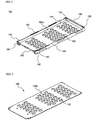
FIGS. 1 and 2 are perspective views respectively illustrating a cartridge body and a top cover constituting a cell module cartridge according to a preferred embodiment of the present invention; -
FIGS. 3 and 4 are typical views illustrating a process for mounting a battery cell to the cell module cartridge ofFIG. 1 ; -
FIG. 5 is a perspective view illustrating a cell module assembled according to a preferred embodiment of the present invention; -
FIGS. 6 to 10 are perspective views illustrating a process for stacking and coupling a plurality of cell module cartridges, one of which is shown inFIGS. 1 to 5 , to manufacture a middle- or large-sized battery module; -
FIG. 11 is a typical view illustrating a process for mounting a second cartridge body to a first cartridge body ofFIG. 4 ; -
FIG. 12 is an enlarged view illustrating the rear of the cartridge body, on which the process ofFIG. 11 is carried out; -
FIGS. 13 to 15 are typical views illustrating various electrode terminal connecting members according to preferred embodiments of the present invention, which are used to manufacture a battery module according to the present invention; -
FIG. 16 is a typical view illustrating a mounting insulation member, to which the electrode terminal connecting members are mounted during the construction of a battery module; and -
FIG. 17 is a typical view illustrating the structure of the middle- or large-sized battery module ofFIG. 8 , which is constructed such that battery cells are connected in series with each other using the electrode terminal connecting members. - Now, preferred embodiments of the present invention will be described in detail with reference to the accompanying drawings. It should be noted, however, that the scope of the present invention is not limited by the illustrated embodiments.
-
FIGS. 1 and 2 are perspective views respectively illustrating a cartridge body and a top cover constituting a cell module cartridge according to a preferred embodiment of the present invention, andFIGS. 3 and 4 are typical views illustrating a process for mounting a battery cell to the cell module cartridge ofFIG. 1 . - Referring to these drawings, the
cartridge body 100 is constructed in a rectangular structure corresponding to a plate-shaped battery cell 200 (hereinafter, will be shortly referred to as a "battery cell") such that thebattery cell 200 is mounted to thecartridge body 100. Thecartridge body 100 is open at the top thereof. Also, thecartridge body 100 is provided at the bottom 110 thereof with a plurality of through-holes 120, arranged in a predetermined pattern, for effectively discharging heat generated from thebattery cell 200 and thus preventing the overheating of thebattery cell 200. The through-holes 120 are divided into several through-hole groups 120a, which are spaced apart from each other by a distance corresponding to eachadhesive tape 300, which will be attached to thebottom 110 of thecartridge body 100. Thetop cover 190 is also provided with a plurality of through-holes 120, which are arranged in a predetermined pattern to divide the through-holes 120 into several through-hole groups 120a. - The
cartridge body 100 is provided at one side of the upper end of eachside wall 130 thereof with acoupling protrusion 140, by which thecartridge body 100 is another cartridge body (not shown). Thecartridge body 100 is provided at one side of the lower end of eachside wall 130 thereof with acoupling groove 142 corresponding to thecoupling protrusion 140. Also, thecartridge body 100 is provided at thefront 150 thereof with acoupling part 152, to which a mountinginsulation member 400 is coupled in an assembly fashion. - The
cartridge body 100 is provided at the upper ends of theopposite side walls 130 thereof with pluralities ofprotrusions 160, which form a coolant channel when another cartridge body (not shown) is stacked on thecartridge body 100. The cartridge bodies are spaced apart a predetermined distance from each other by theprotrusions 160 to form the coolant channel, along which a coolant flows. - Also, the
cartridge body 100 is provided at the upper end of arear wall 170 thereof with a coupling concavo-convex part 180, by which thecartridge body 100 is coupled to another cartridge body. Thecartridge body 100 is provided at the lower end of therear wall 170 thereof with acoupling groove 182 corresponding to the coupling concavo-convex part 180. - The
adhesive tapes 300 may be different depending upon whether theadhesive tapes 300 are attached to the top or bottom of thebattery cell 200. For example, when eachadhesive tape 300 is attached to the top of thebattery cell 200, theadhesive tape 300 may be an elastic single-sided adhesive tape having a predetermined thickness and exhibiting an adhesive property only at one side of eachadhesive tape 300. On the other hand, when eachadhesive tape 300 is attached to the bottom of thebattery cell 200, theadhesive tape 300 may be a double-sided adhesive tape exhibiting an adhesive property at both sides of eachadhesive tape 300. The effect resulting from the attachment of the adhesive tapes is the same as in the above description. -
FIG. 5 is a perspective view illustrating a cell module assembled according to a preferred embodiment of the present invention. - Hereinafter, a process for assembling the cell module will be described with reference to
FIGS. 1 to 4 andFIG. 5 . First, theadhesive tapes 300 are attached to the remaining region of thecartridge body 100, excluding the region of thecartridge body 100 where the through-hole groups 120a are located, and thebattery cell 200 is mounted to thecartridge body 100. Subsequently,electrode terminals battery cell 200 are bent downward, and are brought into tight contact with thecoupling part 152, formed at the front of thecartridge body 100, such that thebent electrode terminals battery cell 200 surround thecoupling part 152. Subsequently, the mountinginsulation member 400 is assembled to thecoupling part 152, with which theelectrode terminals battery cell 200 are in tight contact. Finally, an electrodeterminal connecting member 410 for electrical connection is coupled to the mountinginsulation member 400, theadhesive tapes 300 are attached to the top of thebattery cell 200, and thetop cover 190 is mounted to the top of thebattery cell 200. In this way, thecell module 100a is manufactured. - However, the process for manufacturing the cell module may be changed according to circumstances.
-
FIGS. 6 to 10 are perspective views illustrating a process for stacking and coupling a plurality of cell module cartridges, one of which is shown inFIGS. 1 to 5 , to manufacture a middle- or large-sized battery module. - Referring first to
FIG. 6 , when asecond cartridge body 102 is placed on the top of afirst cartridge body 101, in which the battery cell is mounted, the coupling protrusions 140 (seeFIG. 1 ), which are formed at the upper ends of the opposite side walls of thefirst cartridge body 101, are inserted into the coupling grooves 142 (seeFIG. 1 ), which are formed at the lower ends of the opposite side walls of thesecond cartridge body 102. Consequently, the stable coupling between thefirst cartridge body 101 and thesecond cartridge body 102 is accomplished. - In this coupling process, as shown in
FIG. 11 , the rear of thesecond cartridge body 102 is first coupled to the rear of thefirst cartridge body 101, and then the front of thesecond cartridge body 102 is rotated downward such that thecoupling protrusions 140 can be inserted into the correspondingcoupling grooves 142. - Specifically, as shown in
FIG. 12 , the coupling concavo-convex part 180 is formed at the upper end of the rear wall of thefirst cartridge body 101, and thecoupling groove 182, corresponding to the coupling concavo-convex part 180, are formed at the lower end of the rear wall of thesecond cartridge body 102. Consequently, when the rear of thesecond cartridge body 102 is pushed toward the rear of thefirst cartridge body 101, the coupling concavo-convex part 180 is inserted into thecoupling groove 182, whereby the stable coupling between thefirst cartridge body 101 and thesecond cartridge body 102 is accomplished. - Referring back to
FIG. 6 , when thesecond cartridge body 102 is placed on the top of thefirst cartridge body 101, the twocartridge bodies protrusions 160, formed at the upper ends of theopposite side walls 130 of thefirst cartridge body 101, to definecoolant flow channels - Referring to
FIG. 7 , a plurality ofcartridge bodies FIG. 6 , are sequentially stacked, thetop cover 190 is mounted to the top of theuppermost cartridge body 107, and predetermined electrodeterminal connecting members 500 are coupled to the front of the cartridge stack. The coupling protrusions 140, which are formed at the upper ends of the opposite side walls of theuppermost cartridge body 107, are inserted intocoupling grooves 142 formed at thetop cover 190, whereby the secure coupling between theuppermost cartridge body 107 and thetop cover 190 is accomplished. - A middle- or large-
sized battery module 700, manufactured by the above-described process, is shown inFIG. 8 . A plurality of such middle- or large-sized battery modules 700 may be combined to manufacture a large-sized battery module assembly having a desired capacity and output. An example of the large-sized battery module assembly is shown inFIGS. 9 and 10 . - Referring to these drawings, the middle- or large-
sized battery module 700 is provided at four corners thereof withgrooves 710, into whichcoupling members sized battery module 700 to another battery middle- or large-sized battery module 701 in the lateral direction are inserted. - The
coupling members sized battery modules coupling members grooves battery modules battery module assembly 900 having a large electric capacity or output as shown inFIG. 10 is manufactured. -
FIGS. 13 to 15 are typical views illustrating various electrode terminal connecting members according to preferred embodiments of the present invention, which are used to manufacture a battery module according to the present invention, andFIG. 16 is a typical view illustrating a mounting insulation member, to which the electrode terminal connecting members are mounted during the construction of the battery module. - For easy understanding, the electrode
terminal connecting member 500a shown inFIG. 13 is referred to as an "A-type connecting member," the electrodeterminal connecting member 500b shown inFIG. 14 is referred to as a "B-type connecting member," and the electrodeterminal connecting member 500c shown inFIG. 15 is referred to as a "C-type connecting member." - Referring to these drawings, the electrode
terminal connecting member 500a includes abent coupling part 520a, which is bent to form agroove 540a at the rear of the electrodeterminal connecting member 500a such that an electrode terminal (for example, a cathode terminal) of a battery cell (not shown) is inserted into thegroove 540a, an external input andoutput terminal 510a protruding toward the front of the electrodeterminal connecting member 500a while being bent, and avoltage detection terminal 530a protruding toward the front of the electrodeterminal connecting member 500a while being bent. The electrodeterminal connecting member 500b includes abent coupling part 520b, which is bent to form agroove 540b at the rear of the electrodeterminal connecting member 500b such that an electrode terminal (for example, a cathode terminal) of a battery cell (not shown) is inserted into thegroove 540b, an external input andoutput terminal 510b protruding toward the front of the electrodeterminal connecting member 500b while being bent, and avoltage detection terminal 530b protruding toward the front of the electrodeterminal connecting member 500b while being bent. The electrodeterminal connecting member 500c includes abent coupling part 520c, which is bent to form agroove 540c at the rear of the electrodeterminal connecting member 500c such that an electrode terminal (for example, a cathode terminal) of a battery cell (not shown) is inserted into thegroove 540c, an external input andoutput terminal 510c protruding toward the front of the electrodeterminal connecting member 500c while being bent, and avoltage detection terminal 530c protruding toward the front of the electrodeterminal connecting member 500c while being bent. - The external input and
output terminal 510a and the voltage detection terminal 330a are bent in parallel to the front of the electrodeterminal connecting member 500a. The external input andoutput terminal 510b and thevoltage detection terminal 530b are bent in parallel to the front of the electrodeterminal connecting member 500b. The external input andoutput terminal 510c and thevoltage detection terminal 530c are bent in parallel to the front of the electrodeterminal connecting member 500c. - The
bent coupling parts output terminals terminal connecting member 500b shown inFIG. 14 includes twobent coupling parts output terminals bent coupling parts bent coupling parts output terminals terminal connecting member 500b. Thevoltage detection terminal 530b is located approximately at the middle of the electrodeterminal connecting member 500b. - The external input and
output terminals coupling holes - Referring to
FIG. 16 , the mountinginsulation member 400 is constructed approximately in a rectangular parallelepiped structure. At the rear of the mountinginsulation member 400 is formed acartridge coupling groove 410, in which the front end of a cartridge body (not shown) is inserted. At the front of the mountinginsulation member 400 are formed a pair of electrode terminal through-holes 420, through which electrode terminals of a battery cell, introduced through thecoupling groove 410, are exposed. - At the top of the mounting
insulation member 400, above the electrode terminal through-holes 420, is formed a couplingupper end 430, which is inserted into therear groove bent coupling part terminal connecting member FIGS. 13 to 15 ). - At the front of the mounting
insulation member 400 is also formed a location part 540, in which the external input andoutput terminal voltage detection terminal terminal connecting member FIGS. 13 to 15 ) are stably located. Also, acoupling depression 450 is formed at a position corresponding to thecoupling hole output terminal terminal connecting member insulation member 400. -
FIG. 17 is a typical view illustrating the structure of the middle- or large-sized battery module manufactured inFIG. 8 , which are constructed in a structure in which battery cells are connected in series with each other using the electrode terminal connecting members. - Referring to
FIG. 17 , the middle- or large-sized battery module 700 includes a total of eight battery cells, to each of which a mountinginsulation member 400 is coupled while each battery cell is mounted in acartridge body 100. Specifically, the middle- or large-sized battery module 500 is constructed in a structure in which anA-type connecting member 500a is coupled to a cathode terminal of the battery cell located at the left upper end of thebattery module 700, a C-type connecting member 500c is coupled to an anode terminal located at the right lower end of the battery cell of thebattery module 700, and B-type connecting members 500b are coupled to the remaining electrode terminals, such that the eight battery cells are connected in series with each other (8S). - However, the battery cells, constituting the battery module, may be connected in parallel and/or series with each other in various structures in addition to the electrical connection structure shown in
FIG. 17 . - Although the preferred embodiments of the present invention have been disclosed for illustrative purposes, those skilled in the art will appreciate that various modifications, additions and substitutions are possible, without departing from the scope and spirit of the invention as disclosed in the accompanying claims.
- As apparent from the above description, the cell module cartridge according to the present invention restrains the movement of the battery cell, when the battery is dropped or external impacts are applied to the battery, thereby preventing the occurrence of a short circuit in the battery and providing further improved safety of the battery.
- Furthermore, the cell module cartridge according to the present invention accomplishing easy connection between the electrode terminals while complementing the mechanical strength of the pouch-shaped secondary battery, which is a defect of the pouch-shaped secondary battery. In addition, it is possible to combine the cell module cartridges in various structures depending a desired output and capacity of a battery module. Consequently, a middle- or large-sized battery module, assembled using the cell module cartridge according to the present invention, is preferably used as a power source for electric bicycles (E-bike), electric motorcycles, electric vehicles, or hybrid electric vehicles.
Claims (18)
- A cell module cartridge used for manufacturing a middle- or-large-sized battery module, wherein the cell module cartridge includes
a cartridge body (100) constructed in a rectangular structure corresponding to a plate-shaped secondary battery cell (200) ('battery cell') such that the battery cell (200) is mounted to the cartridge body (100), the cartridge body (100) being open at the top thereof, and a top cover (190) mounted to the open top of the cartridge body (100) while the battery cell (200) is mounted to the cartridge body (100), and wherein
the cartridge body (100) is provided at the bottom thereof with a plurality of through-holes (120) and,
the cartridge body (100) is provided at one side of the upper end of each side wall thereof with a coupling protrusion (140), by which the cartridge body (100) is coupled to another cartridge body (100), while the cartridge body (100) is provided at one side of the lower end of each side wall thereof with a coupling groove (142) corresponding to the coupling protrusion (140), characterised in that:the cartridge body (100) is provided at the front thereof with a coupling part (152), to which a mounting insulation member (400), which is an additional member for mounting an electrode terminal connecting member is coupled in an assembly fashion, such that the electrode terminal connecting member (500) ('member for electrical connection between electrode terminals') is stably connected to a corresponding electrode terminal (210, 220) of the corresponding battery cell (100),in that the mounting insulation member (400) is provided at a rear end thereof with a cartridge coupling groove (410), in which the coupling part (152) of the cartridge body (100) is inserted, andin that the mounting insulation member (400) is provided at a front end thereof with electrode terminal through-holes (420), through which electrode terminals (210, 220) of the battery cell (100), introduced through the cartridge coupling groove (142), are exposed. - The cell module cartridge according to claim 1, wherein the battery cell (100) is a pouch-shaped battery cell constructed in a structure in which an electrode assembly is mounted in a battery case made of a laminate sheet including a resin layer and a metal layer.
- The cell module cartridge according to claim 1, wherein the through-holes (120) are formed at the bottom of the cartridge body (100) in a predetermined pattern.
- The cell module cartridge according to claim 3, wherein the through-holes (120) are divided into several through-hole groups spaced a predetermined distance from each other.
- The cell module cartridge according to claim 1, wherein the coupling protrusions (140) and the coupling grooves (142) are formed at opposite side walls of the cartridge.
- The cell module cartridge according to claim 1, wherein the cartridge body (100) is provided at the upper end of the rear wall thereof with a coupling concavo-convex part (180), by which the cartridge body (100) is coupled to another cartridge body, and the cartridge body (100) is provided at the lower end of the rear wall thereof with a coupling groove (182) corresponding to the coupling concavo-convex part (180).
- The cell module cartridge according to claim 1, wherein the cartridge body (100) is provided at the upper end of each side wall thereof with at least one protrusion (160), which forms a coolant channel when another cartridge body is stacked on the cartridge body (100).
- The cell module cartridge according to claim 1, wherein the cartridge body (100) is provided at the front thereof with vertical grooves, into which members ('coupling members') for coupling the cartridge body (100) to another cartridge body in the lateral direction are inserted.
- The cell module cartridge according to claim 1, wherein the cartridge body (100) and the top cover (190) are made of an insulative material or an insulative surface-coated material.
- The cell module cartridge according to claim 1, wherein
the mounting insulation member (400) is constructed approximately in a hexahedral structure having a size approximately corresponding to the front of the cartridge body (100), and
the mounting insulation member (400) is provided at the top thereof, above the electrode terminal through-holes (420), with a coupling upper end, which is inserted into the electrode terminal connecting member (410). - A cell module including a cartridge according to claim 1 and a battery cell.
- The cell module according to claim 11, wherein at least one double-sided adhesive tape (300) is attached between the cartridge body and the battery cell.
- A middle- or large-sized battery module constructed in a structure in which a plurality of cell modules according to claim 11 are stacked.
- The battery module according to claim 13, wherein the battery module is manufactured by mounting a battery cell to a cartridge body (100), while a top cover (190), constituting each cell module together with the cartridge body, is separated from the cartridge body (100), stacking a plurality of such cartridge bodies, coupling the top cover (190) to the uppermost cartridge body, and mechanically coupling electrode terminal connecting members to the front of the cartridge stack.
- The battery module according to claim 14, wherein an elastic single-sided adhesive tape (300) having a predetermined thickness is attached to the top of each battery cell, constituting the stacked cartridge bodies.
- The battery module according to claim 14, wherein each electrode terminal connecting member (500a) includes
a coupling part (520a) ('bent coupling part') bent to form a groove at the rear of the electrode terminal connecting member (500a) such that an electrode terminal of each battery cell is inserted into the groove,
an external input and output terminal (510a) protruding toward the front of the electrode terminal connecting member (500a) while being bent, and
a voltage detection terminal (530a) protruding toward the front of the electrode terminal connecting member (500a) while being bent. - A high-output, large-capacity battery module assembly including a plurality of battery modules according to claim 14, wherein the battery module assembly is constructed in a structure in which the battery modules are arranged adjacent to each other in the lateral direction, and the battery modules are coupled to each other using coupling members.
- The battery module assembly according to claim 17, wherein the battery module assembly is comprised as a charging and discharging power source for electric vehicles or hybrid electric vehicles.
Applications Claiming Priority (3)
| Application Number | Priority Date | Filing Date | Title |
|---|---|---|---|
| KR1020060092600A KR100921346B1 (en) | 2006-09-25 | 2006-09-25 | Mid-Large Battery Module and Battery Module Assembly |
| KR1020060102640A KR100894407B1 (en) | 2006-10-23 | 2006-10-23 | Cell-Module Cartridge and Cell-Module Including the Same |
| PCT/KR2007/004400 WO2008038914A1 (en) | 2006-09-25 | 2007-09-12 | Cell-module cartridge and mid-large battery module including the same |
Publications (4)
| Publication Number | Publication Date |
|---|---|
| EP2067194A1 EP2067194A1 (en) | 2009-06-10 |
| EP2067194A4 EP2067194A4 (en) | 2015-12-02 |
| EP2067194B1 true EP2067194B1 (en) | 2018-05-30 |
| EP2067194B8 EP2067194B8 (en) | 2018-07-18 |
Family
ID=39230318
Family Applications (1)
| Application Number | Title | Priority Date | Filing Date |
|---|---|---|---|
| EP07808192.4A Active EP2067194B8 (en) | 2006-09-25 | 2007-09-12 | Cell-module cartridge and mid-large battery module including the same |
Country Status (4)
| Country | Link |
|---|---|
| US (1) | US7858229B2 (en) |
| EP (1) | EP2067194B8 (en) |
| JP (1) | JP5259602B2 (en) |
| WO (1) | WO2008038914A1 (en) |
Families Citing this family (55)
| Publication number | Priority date | Publication date | Assignee | Title |
|---|---|---|---|---|
| US10014508B2 (en) | 2006-11-27 | 2018-07-03 | Lg Chem, Ltd. | Battery module assembly |
| KR100920207B1 (en) | 2006-11-27 | 2009-10-06 | 주식회사 엘지화학 | Power Switching Module for Battery Module Assembly |
| US8202645B2 (en) * | 2008-10-06 | 2012-06-19 | Lg Chem, Ltd. | Battery cell assembly and method for assembling the battery cell assembly |
| DE102009018787A1 (en) * | 2009-04-24 | 2010-10-28 | Akasol Engineering Gmbh | battery module |
| JP5393365B2 (en) * | 2009-09-11 | 2014-01-22 | 日産自動車株式会社 | Battery module |
| DE102009052508A1 (en) * | 2009-11-11 | 2011-05-12 | Carl Freudenberg Kg | Mechanically flexible and porous compensating element for tempering electrochemical cells |
| CN102630357B (en) * | 2009-11-27 | 2014-12-24 | Lg电子株式会社 | Battery Cartridge |
| KR101403930B1 (en) | 2010-08-16 | 2014-07-01 | 주식회사 엘지화학 | Battery Pack of Compact Structure |
| KR101271567B1 (en) * | 2010-08-16 | 2013-06-11 | 주식회사 엘지화학 | Battery Module of Structure Having Fixing Member Inserted into Through-Hole of Plates and Battery Pack Employed with the Same |
| KR101243908B1 (en) * | 2010-10-12 | 2013-03-14 | 삼성에스디아이 주식회사 | Battery unit and battery module |
| CN103201879B (en) * | 2010-11-22 | 2015-06-03 | 株式会社Lg化学 | Battery pack having a compact structure |
| EP2693516B1 (en) | 2011-03-31 | 2018-11-21 | NEC Energy Devices, Ltd. | Battery pack |
| JP5831924B2 (en) * | 2011-03-31 | 2015-12-09 | Necエナジーデバイス株式会社 | Battery pack |
| US20140017541A1 (en) * | 2011-03-31 | 2014-01-16 | Nec Energy Devices, Ltd. | Battery pack and electric bicycle |
| JP2012212608A (en) * | 2011-03-31 | 2012-11-01 | Nec Energy Devices Ltd | Battery pack |
| KR101252950B1 (en) | 2011-04-21 | 2013-04-15 | 로베르트 보쉬 게엠베하 | Battery module providing improved fixing structure for end plate |
| KR101355961B1 (en) * | 2011-04-25 | 2014-02-03 | 주식회사 엘지화학 | Apparatus for containing battery pack and apparatus for cooling power storage battery pack using it |
| KR101255542B1 (en) * | 2011-05-12 | 2013-04-16 | 삼성에스디아이 주식회사 | Battery pack |
| KR101282519B1 (en) | 2011-08-02 | 2013-07-04 | 로베르트 보쉬 게엠베하 | Battery module |
| KR101288121B1 (en) * | 2011-08-24 | 2013-07-19 | 삼성에스디아이 주식회사 | Secondary battery and secondary battery module |
| US9450219B2 (en) | 2011-09-15 | 2016-09-20 | Samsung Sdi Co., Ltd. | Battery module |
| KR101883915B1 (en) * | 2011-09-30 | 2018-08-02 | 삼성에스디아이 주식회사 | Battery module having support member |
| WO2013089468A1 (en) | 2011-12-14 | 2013-06-20 | 주식회사 엘지화학 | Battery module assembly having improved reliability and medium or large-sized battery pack including same |
| KR101501431B1 (en) * | 2012-07-23 | 2015-03-12 | 주식회사 엘지화학 | Battery Cell Including Pouch-type Cell and Transformed to Prismatic Shape |
| CN102903865A (en) * | 2012-11-06 | 2013-01-30 | 无锡东港电池配件有限公司 | Battery steel shell structure |
| US9525195B2 (en) * | 2013-07-30 | 2016-12-20 | Johnson Controls Technology Corporation | Remanufacturing methods for battery module |
| KR101692790B1 (en) * | 2013-07-31 | 2017-01-04 | 주식회사 엘지화학 | Battery Module Assembly Having Coolant Flow Channel |
| KR101709562B1 (en) | 2013-07-31 | 2017-03-08 | 주식회사 엘지화학 | Battery Module Assembly |
| WO2015026202A1 (en) | 2013-08-23 | 2015-02-26 | 주식회사 엘지화학 | Stackable battery module having easily modifiable connection structure |
| JP6233076B2 (en) * | 2014-02-06 | 2017-11-22 | 株式会社豊田自動織機 | Battery module |
| KR101767634B1 (en) * | 2014-07-31 | 2017-08-14 | 주식회사 엘지화학 | Battery module |
| WO2016068551A1 (en) | 2014-10-29 | 2016-05-06 | 주식회사 엘지화학 | Unit battery pack |
| KR101787638B1 (en) | 2014-11-05 | 2017-10-19 | 주식회사 엘지화학 | Cartridge Frame Having Double Sidewall Structure and Battery Module Having the Same |
| US9991501B2 (en) | 2015-01-05 | 2018-06-05 | Johnson Controls Technology Company | Vent shield for a battery module |
| JP6400838B2 (en) * | 2015-03-31 | 2018-10-03 | 三洋電機株式会社 | Power supply device and vehicle equipped with the same |
| KR101881196B1 (en) | 2015-06-16 | 2018-07-23 | 주식회사 엘지화학 | Battery Pack |
| KR101953362B1 (en) * | 2015-09-02 | 2019-05-22 | 주식회사 엘지화학 | Battery Module having an improved coupling structure |
| KR102024326B1 (en) * | 2015-10-14 | 2019-09-23 | 주식회사 엘지화학 | Battery module and battery pack comprising the smae |
| WO2017104877A1 (en) * | 2015-12-18 | 2017-06-22 | 주식회사 엘지화학 | Battery module |
| WO2018033880A2 (en) | 2016-08-17 | 2018-02-22 | Shape Corp. | Battery support and protection structure for a vehicle |
| WO2018127832A1 (en) | 2017-01-04 | 2018-07-12 | Shape Corp. | Vehicle battery tray structure with nodal modularity |
| KR102097087B1 (en) | 2017-04-07 | 2020-04-03 | 주식회사 엘지화학 | Battery module, battery pack including the same, and vehicle including the same |
| WO2018213475A1 (en) | 2017-05-16 | 2018-11-22 | Shape Corp. | Polarized battery tray for a vehicle |
| WO2018213306A1 (en) | 2017-05-16 | 2018-11-22 | Shape Corp. | Vehicle battery tray having tub-based component |
| WO2018213383A1 (en) | 2017-05-16 | 2018-11-22 | Shape Corp. | Vehicle battery tray with integrated battery retention and support features |
| CN111108015A (en) | 2017-09-13 | 2020-05-05 | 形状集团 | Vehicle battery tray with tubular peripheral wall |
| CN111201155A (en) | 2017-10-04 | 2020-05-26 | 形状集团 | Battery tray bottom plate assembly for electric vehicle |
| KR102059614B1 (en) * | 2017-11-14 | 2019-12-26 | 주식회사 엘지화학 | Battery pack having fixing parts |
| US10766437B2 (en) * | 2017-12-14 | 2020-09-08 | Volkswagen Ag | Electric vehicle safety system and methods |
| WO2019169080A1 (en) | 2018-03-01 | 2019-09-06 | Shape Corp. | Cooling system integrated with vehicle battery tray |
| US11688910B2 (en) | 2018-03-15 | 2023-06-27 | Shape Corp. | Vehicle battery tray having tub-based component |
| KR102523702B1 (en) | 2018-07-03 | 2023-04-19 | 주식회사 엘지에너지솔루션 | Battery module |
| JP6683779B2 (en) * | 2018-08-31 | 2020-04-22 | 本田技研工業株式会社 | Battery pack cooling structure |
| JP6706294B2 (en) * | 2018-08-31 | 2020-06-03 | 本田技研工業株式会社 | Battery pack cooling structure |
| CN110429223A (en) * | 2019-09-05 | 2019-11-08 | 珠海格力电器股份有限公司 | Battery core fixed structure, battery module, battery modules |
Family Cites Families (20)
| Publication number | Priority date | Publication date | Assignee | Title |
|---|---|---|---|---|
| JP3627480B2 (en) * | 1997-11-28 | 2005-03-09 | 松下電器産業株式会社 | Battery |
| US6319631B1 (en) * | 1999-09-08 | 2001-11-20 | Motorola, Inc. | Contact system for interconnection of substrate and battery cell |
| JP4642179B2 (en) * | 1999-10-08 | 2011-03-02 | パナソニック株式会社 | Collective secondary battery |
| KR100362277B1 (en) | 2000-04-10 | 2002-11-23 | 삼성에스디아이 주식회사 | Secondary battery having protective case |
| JP4196521B2 (en) * | 2000-05-19 | 2008-12-17 | 新神戸電機株式会社 | Battery structure and battery module for electric vehicle |
| JP4214450B2 (en) * | 2002-06-03 | 2009-01-28 | 日本電気株式会社 | module |
| JP3644444B2 (en) * | 2002-07-23 | 2005-04-27 | 日産自動車株式会社 | Module battery |
| JP2005116407A (en) * | 2003-10-09 | 2005-04-28 | Tdk Corp | Battery pack |
| JP4430075B2 (en) | 2003-10-14 | 2010-03-10 | エルジー・ケム・リミテッド | Cartridge type lithium ion polymer battery pack |
| JP4706170B2 (en) | 2003-10-14 | 2011-06-22 | 株式会社Gsユアサ | Assembled battery |
| KR100556101B1 (en) * | 2003-12-16 | 2006-03-03 | 주식회사 엘지화학 | Secondary battery module |
| JP4400234B2 (en) * | 2004-02-03 | 2010-01-20 | 新神戸電機株式会社 | Assembled battery |
| KR100645263B1 (en) * | 2004-02-18 | 2006-11-14 | 주식회사 엘지화학 | Unification Type Cap Assembly Containing Protection Circuit Board And Secondary Battery Comprising the Same |
| JP4617098B2 (en) * | 2004-04-12 | 2011-01-19 | 内山工業株式会社 | Case for battery cell |
| KR100891080B1 (en) | 2004-12-02 | 2009-03-30 | 주식회사 엘지화학 | Battery Cell-Connecting Member for Preparation of Battery Pack |
| KR100850849B1 (en) | 2004-12-09 | 2008-08-06 | 주식회사 엘지화학 | Battery case for thermal control and battery pack structure using the same |
| KR100905391B1 (en) * | 2004-12-24 | 2009-06-30 | 주식회사 엘지화학 | Terminal-linking Member of Secondary Battery Module |
| KR100880389B1 (en) * | 2004-12-24 | 2009-01-23 | 주식회사 엘지화학 | Process for Preparation of Secondary Battery Module |
| KR100876458B1 (en) * | 2004-12-24 | 2008-12-29 | 주식회사 엘지화학 | Battery cartridge of novel structure and open battery module containing it |
| KR100891079B1 (en) * | 2005-02-07 | 2009-03-30 | 주식회사 엘지화학 | Battery Cartridge-connecting System For Battery Module |
-
2007
- 2007-09-12 WO PCT/KR2007/004400 patent/WO2008038914A1/en active Application Filing
- 2007-09-12 EP EP07808192.4A patent/EP2067194B8/en active Active
- 2007-09-12 US US12/442,614 patent/US7858229B2/en active Active
- 2007-09-12 JP JP2009530251A patent/JP5259602B2/en active Active
Non-Patent Citations (1)
| Title |
|---|
| None * |
Also Published As
| Publication number | Publication date |
|---|---|
| EP2067194A1 (en) | 2009-06-10 |
| JP5259602B2 (en) | 2013-08-07 |
| US7858229B2 (en) | 2010-12-28 |
| EP2067194A4 (en) | 2015-12-02 |
| EP2067194B8 (en) | 2018-07-18 |
| WO2008038914A1 (en) | 2008-04-03 |
| JP2010504622A (en) | 2010-02-12 |
| US20100136420A1 (en) | 2010-06-03 |
Similar Documents
| Publication | Publication Date | Title |
|---|---|---|
| EP2067194B1 (en) | Cell-module cartridge and mid-large battery module including the same | |
| US7976978B2 (en) | Member of connecting electrode in battery module | |
| EP1812982B1 (en) | Secondary battery pack having configuration of alternative orientation | |
| EP1994581B1 (en) | Middle or large-sized battery module | |
| CN101517784B (en) | Cell-module cartridge and mid-large battery module including the same | |
| EP2535962B1 (en) | Battery module having enhanced welding reliability and medium or large battery pack including same | |
| US7892669B2 (en) | Middle or large-sized battery module | |
| EP2025019B1 (en) | Middle or large-sized battery module | |
| EP2064761B1 (en) | Battery module and middle or large-sized battery pack containing the same | |
| EP1992026B1 (en) | Battery module | |
| EP2853436B1 (en) | Battery module including indirect air cooling structure | |
| EP2765632A1 (en) | Battery module assembly having improved reliability and medium or large-sized battery pack including same | |
| WO2009061088A1 (en) | Battery cell having improved thermal stability and middle or large-sized battery module employed with the same | |
| KR20080074239A (en) | High capacity battery cell of high life characteristics and safety | |
| KR20120074415A (en) | Unit module of novel structure and battery module comprising the same |
Legal Events
| Date | Code | Title | Description |
|---|---|---|---|
| PUAI | Public reference made under article 153(3) epc to a published international application that has entered the european phase |
Free format text: ORIGINAL CODE: 0009012 |
|
| 17P | Request for examination filed |
Effective date: 20090323 |
|
| AK | Designated contracting states |
Kind code of ref document: A1 Designated state(s): AT BE BG CH CY CZ DE DK EE ES FI FR GB GR HU IE IS IT LI LT LU LV MC MT NL PL PT RO SE SI SK TR |
|
| AX | Request for extension of the european patent |
Extension state: AL BA HR MK RS |
|
| DAX | Request for extension of the european patent (deleted) | ||
| RBV | Designated contracting states (corrected) |
Designated state(s): DE FR GB IT |
|
| RA4 | Supplementary search report drawn up and despatched (corrected) |
Effective date: 20151102 |
|
| RIC1 | Information provided on ipc code assigned before grant |
Ipc: H01M 2/22 20060101AFI20151027BHEP |
|
| GRAP | Despatch of communication of intention to grant a patent |
Free format text: ORIGINAL CODE: EPIDOSNIGR1 |
|
| INTG | Intention to grant announced |
Effective date: 20180214 |
|
| GRAS | Grant fee paid |
Free format text: ORIGINAL CODE: EPIDOSNIGR3 |
|
| GRAA | (expected) grant |
Free format text: ORIGINAL CODE: 0009210 |
|
| AK | Designated contracting states |
Kind code of ref document: B1 Designated state(s): DE FR GB IT |
|
| GRAT | Correction requested after decision to grant or after decision to maintain patent in amended form |
Free format text: ORIGINAL CODE: EPIDOSNCDEC |
|
| REG | Reference to a national code |
Ref country code: GB Ref legal event code: FG4D |
|
| REG | Reference to a national code |
Ref country code: DE Ref legal event code: R096 Ref document number: 602007054992 Country of ref document: DE |
|
| RAP2 | Party data changed (patent owner data changed or rights of a patent transferred) |
Owner name: LG CHEM, LTD. |
|
| REG | Reference to a national code |
Ref country code: DE Ref legal event code: R082 Ref document number: 602007054992 Country of ref document: DE Representative=s name: HOFFMANN - EITLE PATENT- UND RECHTSANWAELTE PA, DE |
|
| REG | Reference to a national code |
Ref country code: FR Ref legal event code: PLFP Year of fee payment: 12 |
|
| RAP2 | Party data changed (patent owner data changed or rights of a patent transferred) |
Owner name: LG CHEM, LTD. |
|
| PG25 | Lapsed in a contracting state [announced via postgrant information from national office to epo] |
Ref country code: IT Free format text: LAPSE BECAUSE OF FAILURE TO SUBMIT A TRANSLATION OF THE DESCRIPTION OR TO PAY THE FEE WITHIN THE PRESCRIBED TIME-LIMIT Effective date: 20180530 |
|
| REG | Reference to a national code |
Ref country code: DE Ref legal event code: R097 Ref document number: 602007054992 Country of ref document: DE |
|
| PLBE | No opposition filed within time limit |
Free format text: ORIGINAL CODE: 0009261 |
|
| STAA | Information on the status of an ep patent application or granted ep patent |
Free format text: STATUS: NO OPPOSITION FILED WITHIN TIME LIMIT |
|
| 26N | No opposition filed |
Effective date: 20190301 |
|
| REG | Reference to a national code |
Ref country code: DE Ref legal event code: R079 Ref document number: 602007054992 Country of ref document: DE Free format text: PREVIOUS MAIN CLASS: H01M0002220000 Ipc: H01M0050528000 |
|
| P01 | Opt-out of the competence of the unified patent court (upc) registered |
Effective date: 20230408 |
|
| REG | Reference to a national code |
Ref country code: DE Ref legal event code: R081 Ref document number: 602007054992 Country of ref document: DE Owner name: LG ENERGY SOLUTION, LTD., KR Free format text: FORMER OWNER: LG CHEM, LTD., SEOUL, KR |
|
| REG | Reference to a national code |
Ref country code: GB Ref legal event code: 732E Free format text: REGISTERED BETWEEN 20230824 AND 20230831 |
|
| PGFP | Annual fee paid to national office [announced via postgrant information from national office to epo] |
Ref country code: GB Payment date: 20230821 Year of fee payment: 17 |
|
| PGFP | Annual fee paid to national office [announced via postgrant information from national office to epo] |
Ref country code: FR Payment date: 20230821 Year of fee payment: 17 Ref country code: DE Payment date: 20230822 Year of fee payment: 17 |