EP4513629A1 - Wärmeverwaltungskomponente, batterie und elektrische vorrichtung - Google Patents
Wärmeverwaltungskomponente, batterie und elektrische vorrichtung Download PDFInfo
- Publication number
- EP4513629A1 EP4513629A1 EP23795231.2A EP23795231A EP4513629A1 EP 4513629 A1 EP4513629 A1 EP 4513629A1 EP 23795231 A EP23795231 A EP 23795231A EP 4513629 A1 EP4513629 A1 EP 4513629A1
- Authority
- EP
- European Patent Office
- Prior art keywords
- wall
- thermal management
- management component
- reinforcing member
- battery
- Prior art date
- Legal status (The legal status is an assumption and is not a legal conclusion. Google has not performed a legal analysis and makes no representation as to the accuracy of the status listed.)
- Pending
Links
Images
Classifications
-
- F—MECHANICAL ENGINEERING; LIGHTING; HEATING; WEAPONS; BLASTING
- F28—HEAT EXCHANGE IN GENERAL
- F28F—DETAILS OF HEAT-EXCHANGE AND HEAT-TRANSFER APPARATUS, OF GENERAL APPLICATION
- F28F1/00—Tubular elements; Assemblies of tubular elements
- F28F1/02—Tubular elements of cross-section which is non-circular
- F28F1/022—Tubular elements of cross-section which is non-circular with multiple channels
-
- H—ELECTRICITY
- H01—ELECTRIC ELEMENTS
- H01M—PROCESSES OR MEANS, e.g. BATTERIES, FOR THE DIRECT CONVERSION OF CHEMICAL ENERGY INTO ELECTRICAL ENERGY
- H01M10/00—Secondary cells; Manufacture thereof
- H01M10/60—Heating or cooling; Temperature control
- H01M10/61—Types of temperature control
- H01M10/613—Cooling or keeping cold
-
- H—ELECTRICITY
- H01—ELECTRIC ELEMENTS
- H01M—PROCESSES OR MEANS, e.g. BATTERIES, FOR THE DIRECT CONVERSION OF CHEMICAL ENERGY INTO ELECTRICAL ENERGY
- H01M10/00—Secondary cells; Manufacture thereof
- H01M10/60—Heating or cooling; Temperature control
- H01M10/61—Types of temperature control
- H01M10/617—Types of temperature control for achieving uniformity or desired distribution of temperature
-
- H—ELECTRICITY
- H01—ELECTRIC ELEMENTS
- H01M—PROCESSES OR MEANS, e.g. BATTERIES, FOR THE DIRECT CONVERSION OF CHEMICAL ENERGY INTO ELECTRICAL ENERGY
- H01M10/00—Secondary cells; Manufacture thereof
- H01M10/60—Heating or cooling; Temperature control
- H01M10/62—Heating or cooling; Temperature control specially adapted for specific applications
- H01M10/625—Vehicles
-
- H—ELECTRICITY
- H01—ELECTRIC ELEMENTS
- H01M—PROCESSES OR MEANS, e.g. BATTERIES, FOR THE DIRECT CONVERSION OF CHEMICAL ENERGY INTO ELECTRICAL ENERGY
- H01M10/00—Secondary cells; Manufacture thereof
- H01M10/60—Heating or cooling; Temperature control
- H01M10/65—Means for temperature control structurally associated with the cells
- H01M10/655—Solid structures for heat exchange or heat conduction
- H01M10/6554—Rods or plates
- H01M10/6555—Rods or plates arranged between the cells
-
- H—ELECTRICITY
- H01—ELECTRIC ELEMENTS
- H01M—PROCESSES OR MEANS, e.g. BATTERIES, FOR THE DIRECT CONVERSION OF CHEMICAL ENERGY INTO ELECTRICAL ENERGY
- H01M10/00—Secondary cells; Manufacture thereof
- H01M10/60—Heating or cooling; Temperature control
- H01M10/65—Means for temperature control structurally associated with the cells
- H01M10/655—Solid structures for heat exchange or heat conduction
- H01M10/6556—Solid parts with flow channel passages or pipes for heat exchange
- H01M10/6557—Solid parts with flow channel passages or pipes for heat exchange arranged between the cells
-
- H—ELECTRICITY
- H01—ELECTRIC ELEMENTS
- H01M—PROCESSES OR MEANS, e.g. BATTERIES, FOR THE DIRECT CONVERSION OF CHEMICAL ENERGY INTO ELECTRICAL ENERGY
- H01M10/00—Secondary cells; Manufacture thereof
- H01M10/60—Heating or cooling; Temperature control
- H01M10/65—Means for temperature control structurally associated with the cells
- H01M10/656—Means for temperature control structurally associated with the cells characterised by the type of heat-exchange fluid
- H01M10/6567—Liquids
- H01M10/6568—Liquids characterised by flow circuits, e.g. loops, located externally to the cells or cell casings
-
- H—ELECTRICITY
- H01—ELECTRIC ELEMENTS
- H01M—PROCESSES OR MEANS, e.g. BATTERIES, FOR THE DIRECT CONVERSION OF CHEMICAL ENERGY INTO ELECTRICAL ENERGY
- H01M50/00—Constructional details or processes of manufacture of the non-active parts of electrochemical cells other than fuel cells, e.g. hybrid cells
- H01M50/20—Mountings; Secondary casings or frames; Racks, modules or packs; Suspension devices; Shock absorbers; Transport or carrying devices; Holders
- H01M50/233—Mountings; Secondary casings or frames; Racks, modules or packs; Suspension devices; Shock absorbers; Transport or carrying devices; Holders characterised by physical properties of casings or racks, e.g. dimensions
- H01M50/242—Mountings; Secondary casings or frames; Racks, modules or packs; Suspension devices; Shock absorbers; Transport or carrying devices; Holders characterised by physical properties of casings or racks, e.g. dimensions adapted for protecting batteries against vibrations, collision impact or swelling
-
- F—MECHANICAL ENGINEERING; LIGHTING; HEATING; WEAPONS; BLASTING
- F28—HEAT EXCHANGE IN GENERAL
- F28F—DETAILS OF HEAT-EXCHANGE AND HEAT-TRANSFER APPARATUS, OF GENERAL APPLICATION
- F28F2225/00—Reinforcing means
- F28F2225/04—Reinforcing means for conduits
-
- Y—GENERAL TAGGING OF NEW TECHNOLOGICAL DEVELOPMENTS; GENERAL TAGGING OF CROSS-SECTIONAL TECHNOLOGIES SPANNING OVER SEVERAL SECTIONS OF THE IPC; TECHNICAL SUBJECTS COVERED BY FORMER USPC CROSS-REFERENCE ART COLLECTIONS [XRACs] AND DIGESTS
- Y02—TECHNOLOGIES OR APPLICATIONS FOR MITIGATION OR ADAPTATION AGAINST CLIMATE CHANGE
- Y02E—REDUCTION OF GREENHOUSE GAS [GHG] EMISSIONS, RELATED TO ENERGY GENERATION, TRANSMISSION OR DISTRIBUTION
- Y02E60/00—Enabling technologies; Technologies with a potential or indirect contribution to GHG emissions mitigation
- Y02E60/10—Energy storage using batteries
Definitions
- This application relates to the field of battery technologies, and specifically to a thermal management component, a battery, and an electric apparatus.
- the battery cell in the battery is prone to swelling in shape as the use time increases, which easily reduces the contact area between the battery cell and the thermal management component in the battery, affecting the efficiency of heat conduction between the thermal management component and the battery cell.
- This application provides a thermal management component, a battery, and an electric apparatus, so that the thermal management component can be compressed and undergo slight deformation, thereby reducing the impact of swelling of the battery cell on heat conduction between the battery cell and the thermal management component.
- an embodiments of this application provides a thermal management component including: a first wall; a second wall spaced apart from the first wall, where an accommodating space is present between the first wall and the second wall; and a support member, where the support member is disposed in the accommodating space oblique to an extension direction of the first wall or the second wall.
- the thermal management component includes the first wall and the second wall spaced apart from the first wall, and the accommodating space is present between the first wall and the second wall.
- the accommodating space can be used to accommodate a heat exchange medium such as a medium that can be used for heat exchange after cooling or a medium that can be used for heat exchange after heating, specifically, for example, water or a cooling liquid, so that when at least one of the first wall and the second wall is in contact with a target member such as a battery cell or a battery module, temperature of the target member is adjusted through heat transfer.
- the support member in this application provides a small supporting force on the first wall and the second wall, making the thermal management component likely to undergo slight deformation when the thermal management component is subjected to an extrusion force in a stacking direction of the first wall and the second wall, thereby meeting the need for the battery pack to be deformable when compressed, for example, during sealing for assembly. In addition, this can also reduce the risk of damage to the thermal management component under large concentrated stress.
- the support member is provided in plurality, the plurality of support members being spaced apart between the first wall and the second wall.
- the plurality of support members can divide the accommodating space into a plurality of flow channels. Therefore, when the heat exchange medium enters the accommodating space, the heat exchange medium can be distributed into the plurality of flow channels, thereby evenly regulating the temperature of the target member at various portions when the thermal management component is in contact with the target member.
- the support members being spaced apart can prevent the thermal management component from being difficult to compress due to high local strength, thereby improving overall reliability of the heat exchange function.
- the first wall is configured to come into contact with a target member for heat conduction; and an included angle between the support member and a direction perpendicular to a plane on which the first wall is located is within a range of 35° to 55°.
- the support member when the included angle between the support member and the direction perpendicular to the plane on which the first wall is located is less than 35°, the support member provides a large supporting force on the first wall and the second wall, making the thermal management component less likely to be compressed.
- the support member When the included angle between the support member and the direction perpendicular to the plane on which the first wall is located is greater than 55°, the support member provides a small supporting force on the first wall and the second wall, causing damage to the thermal management component under large concentrated stress, or causing the thermal management component to come into contact with the second wall to block the accommodating space due to large compressive deformation.
- the included angle between the support member and the direction perpendicular to the plane on which the first wall is located being set within the range of 35° to 55° can allow the thermal management component to be easily compressed and undergo slight deformation, and reduce the risk of damage to the thermal management component under large concentrated stress, or avoid the situation where the thermal management component comes into contact with the second wall to block the accommodating space due to large compressive deformation.
- a plurality of support members are disposed in parallel.
- the included angles between the plurality of support members and the direction perpendicular to the plane on which the first wall is located are all the same, and each support member provides the same supporting force on the first wall and the second wall, which can reduce the risk of deformation of the thermal management component due to large local force, and also helps improve aesthetic appearance of the product.
- At least two of the support members each form a different included angle with the first wall.
- At least two support members may alternatively be set at different included angles with the plane on which the first wall is located, for example, one support member forms an included angle of 35° with the plane on which the first wall is located, and an adjacent support member forms an included angle of 45° with the plane on which the first wall is located.
- This can also support the first wall and the second wall, and can allow the thermal management component to undergo slight deformation, with simple structure and principle which are easy to implement.
- the thermal management component includes a connecting end, where the connecting end is located between the first wall and the second wall and connects the first wall and the second wall, and the thermal management component further includes at least one end portion reinforcing member disposed between the first wall and the second wall and close to the connecting end.
- the end portion reinforcing member supports the connecting end between the first connecting wall and the second connecting wall, which enhances local strength of the connecting end, preventing damage to the connecting end under large stress.
- the end portion reinforcing member is provided in two, and the two end portion support members are configured to support two connecting ends between the first wall and the second wall respectively.
- a gap is provided between the end portion reinforcing member and the connecting end.
- the end portion reinforcing member is spaced apart from the connecting end, so that the heat exchange medium can flow through the gap between the end portion reinforcing member and the connecting end, allowing the connecting end to also conduct heat, thereby further improving uniformity of heat conduction of the thermal management component.
- the thermal management component further includes a first reinforcing member, where the first reinforcing member is disposed on a surface of the first wall facing the second wall, and the first reinforcing member is spaced apart from the second wall.
- the first reinforcing member not only can enhance stiffness of the first wall, but also can avoid direct contact between the first wall and the second wall when the thermal management component is compressed and deformed, thereby preventing the situation where the heat exchange medium cannot flow through caused by the accommodating space being blocked.
- the thermal management component further includes a second reinforcing member, where the second reinforcing member is disposed on a surface of the second wall facing the first wall and is spaced apart from the first wall.
- the second reinforcing member not only can enhance stiffness of the second wall, but also can further avoid direct contact between the second wall and the first wall when the thermal management component is compressed and deformed, thereby further preventing the situation where the heat exchange medium cannot flow through caused by the accommodating space being blocked.
- the second reinforcing member and the first reinforcing member are staggered.
- the first reinforcing member and the second reinforcing member staggered in the stacking direction of the first wall and the second wall, the first reinforcing member and the second reinforcing member can be prevented from abutting against each other when the first wall and the second wall are compressed to move close to each other, thereby avoiding the situation where the thermal management component cannot deformed when compressed due to the fact the first reinforcing member abuts against the second reinforcing member.
- the first reinforcing member and/or the second reinforcing member in a stacking direction of the first wall and the second wall, has a smaller size than the end portion reinforcing member.
- the first reinforcing member has a smaller size than the end portion reinforcing member in the stacking direction of the first wall and the second wall
- the second reinforcing member has a smaller size than the end portion reinforcing member in the stacking direction of the first wall and the second wall
- both the first reinforcing member and the second reinforcing member have a smaller size than the end portion reinforcing member in the stacking direction of the first wall and the second wall.
- the end portion reinforcing member supports the first wall and the second wall, and the first reinforcing member and the second reinforcing member prevent indentations for direct contact between the first wall and the second wall due to being compressed and deformed
- the first reinforcing member and the second reinforcing member having a smaller size than the end portion reinforcing member in the stacking direction of the first wall and the second wall can prevent damage to the connecting end between the first wall and the second wall under large stress, and also prevent direct contact between the first wall and the second wall when the thermal management component is compressed, thereby avoiding the accommodating space being blocked.
- an embodiment of this application provides a battery including: a target member; and the thermal management component according to any one of the embodiments of the first aspect, where the thermal management component is in thermally conductive contact with the target member through the first wall.
- the target member may be a component such as a battery cell group.
- the battery provided in the embodiments of the second aspect includes the thermal management component according to any one of the embodiments of the first aspect, and therefore has the technical effects of any one of the foregoing embodiments, which are not described herein again.
- the battery further includes a fluid collecting component, where the fluid collecting component is connected to the thermal management component, the fluid collecting component includes a fluid collecting flow channel, and the fluid collecting flow channel communicates with the accommodating space of the thermal management component.
- the fluid collecting flow channel of the fluid collecting component communicating with the accommodating space of the thermal management component can allow the heat exchange medium to enter the accommodating space via the fluid collecting component, so as to adjust temperature of the target member.
- the heat exchange medium in the accommodating space can return to the fluid collecting component after heat exchange, thereby implementing cyclic heat conduction.
- an embodiment of this application provides an electric apparatus including the battery according to the embodiments of the second aspect, where the battery is configured to supply power to the electric apparatus.
- vehicle 1000 battery 100, controller 200, motor 300; box 10, first portion 11, second portion 12; battery cell 20, thermal management component 30, target member 40; first wall 301, second wall 302, accommodating space 303, support member 304, end portion reinforcing member 305, connecting end 306, first reinforcing member 307, and second reinforcing member 308.
- the term "and/or" is only an associative relationship for describing associated objects, indicating that three relationships may be present.
- a and/or B may indicate the following three cases: presence of only A, presence of both A and B, and presence of only B.
- the character "/" in this specification generally indicates an "or" relationship between the contextually associated objects.
- a plurality of means more than two (inclusive).
- a plurality of groups means more than two (inclusive) groups
- a plurality of pieces means more than two (inclusive) pieces.
- the technical terms “mounting”, “connection”, “join”, and “fixing” should be understood in their general senses. For example, they may refer to a fixed connection, a detachable connection, or an integral connection, may refer to a mechanical connection or an electrical connection, and may refer to a direct connection, an indirect connection via an intermediate medium, an internal communication between two elements, or an interaction between two elements. Persons of ordinary skill in the art can understand specific meanings of these terms in the embodiments of this application as appropriate to specific situations.
- Traction batteries have been not only used in energy storage power supply systems such as hydroelectric power plants, thermal power plants, wind power plants, and solar power plants, but also widely used in many other fields including electric transportation tools such as electric bicycles, electric motorcycles, and electric vehicles, military equipment, and aerospace. With the continuous expansion of application fields of traction batteries, market demands for traction batteries are also increasing.
- Traction batteries exhibit different electrical cycling performance at different ambient temperatures. An excessively high or low ambient temperature leads to deteriorated cycling performance of traction batteries and even shortens their service life.
- effective thermal management is essential for battery modules, which controls the battery modules to always operate within an appropriate temperature range.
- the inventors have found that as use time of a battery increases, a battery cell in the battery is prone to swelling in shape due to internal gas generation, which reduces a heat conduction area between the battery cell or a module formed by a plurality of battery cells and a thermal management component, lowering heat exchange efficiency and resulting in poor effect.
- a support member is provided between a first wall and a second wall of the thermal management component, and the support member is disposed in an accommodating space oblique to an extension direction of the first wall and the second wall. This can appropriately weaken a supporting force of the support member on the first wall and the second wall, so that the thermal management component can be accordingly compressed and undergo slight deformation when the battery cell or battery module swells in shape, thereby mitigating the reduction in the heat exchange area therebetween.
- the thermal management component and battery provided in the embodiments of this application can be used in various electric apparatuses to solve the foregoing problems.
- the electric apparatus may be but is not limited to a mobile phone, a tablet, a notebook computer, an electric toy, an electric tool, an electric bicycle, an electric vehicle, a ship, or a spacecraft.
- the electric toy may include a fixed or mobile electric toy, for example, a game console, an electric toy car, an electric toy ship, and an electric toy airplane.
- the spacecraft may include an airplane, a rocket, a space shuttle, a spaceship, and the like.
- the electric apparatus of an embodiment of this application being a vehicle 1000 is used as an example for description of the following embodiments.
- FIG. 1 is a schematic structural diagram of a vehicle 1000 according to some embodiments of this application.
- the vehicle 1000 may be a fossil fuel vehicle, a natural gas vehicle, or a new energy vehicle.
- the new energy vehicle may be a battery electric vehicle, a hybrid electric vehicle, a range-extended electric vehicle, or the like.
- the vehicle 1000 is provided with a battery 100 inside, where the battery 100 may be disposed at the bottom, front, or rear of the vehicle 1000.
- the battery 100 may be configured to supply power to the vehicle 1000.
- the battery 100 may be used as an operational power source for the vehicle 1000.
- the vehicle 1000 may further include a controller 200 and a motor 300, where the controller 200 is configured to control the battery 100 to supply power to the motor 300, for example, to satisfy power needs of start, navigation, and driving of the vehicle 1000.
- the battery 100 can be used as not only the operational power source for the vehicle 1000 but also a driving power source for the vehicle 1000, replacing or partially replacing fossil fuel or natural gas to provide driving traction for the vehicle 1000.
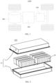
- FIG. 2 is a schematic structural exploded view of a battery 100 according to some embodiments of this application.
- the battery 100 includes a box 10 and a battery cell 20, where the battery cell 20 is accommodated in the box 10.
- the box 10 is configured to provide an accommodating space for the battery cell 20.
- the box 10 may be a variety of structures.
- the box 10 may include a first portion 11 and a second portion 12.
- the first portion 11 and the second portion 12 fit together to jointly define an accommodating space for accommodating the battery cell 20.
- the second portion 12 may be a hollow structure with an opening at one end, the first portion 11 may be a plate-shaped structure, and the first portion 11 covers the opening side of the second portion 12 so that the first portion 11 and the second portion 12 jointly define the accommodating space.
- both the first portion 11 and the second portion 12 may be hollow structures with an opening at one side, and the opening side of the first portion 11 is engaged with the opening side of the second portion 12.
- the box 10 formed by the first portion 11 and the second portion 12 may be of various shapes, for example, cylinder or cuboid.
- the battery cell 20 is present in plurality, and the plurality of battery cells 20 may be connected in series, parallel, or series-parallel, where being connected in series-parallel means a combination of series and parallel connections of the plurality of battery cells 20.
- the plurality of battery cells 20 may be directly connected in series, parallel, or series-parallel, and then an entirety of the plurality of battery cells 20 is accommodated in the box 10; or certainly, the battery 100 may be formed by a plurality of battery cells 20 being connected in series, parallel, or series-parallel first to form a battery module and then a plurality of battery modules being connected in series, parallel, or series-parallel to form an entirety which is accommodated in the box 10.
- the battery 100 may further include an electrical connecting member configured to implement electrical connection between the plurality of battery cells 20.
- the battery cell 20 is a smallest element constituting the battery 100. As shown in FIG. 3 , the battery cell 20 includes an electrical connecting member, where the electrical connecting member is configured to electrically connect two adjacent battery cells 20.
- Each battery cell 20 may be a secondary battery cell or a primary battery cell, and may be a lithium-sulfur battery cell, a sodium-ion battery cell, or a magnesium-ion battery cell, without being limited thereto.
- the battery cell 20 may be cylindrical, flat, cuboid, or of other shapes.
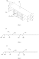
- FIG. 3 is a partial schematic structural diagram of a battery according to some embodiments of this application.
- the battery 20 provided in these embodiments of this application includes a target member and a thermal management component 30.
- a first wall of the thermal management component 30 is configured to come into contact with the target member and perform heat exchange with the target member.
- the target member may be a component such as a battery cell or a battery module.
- the battery 20 further includes a fluid collecting component, where the fluid collecting component is connected to the thermal management component 30, the fluid collecting component includes a fluid collecting flow channel, and the fluid collecting flow channel communicates with an accommodating space 303 of the thermal management component 30.
- the fluid collecting flow channel of the fluid collecting component communicating with the accommodating space 303 of the thermal management component 30 can allow a heat exchange medium to enter the accommodating space 303 via the fluid collecting component, so as to adjust temperature of the target member.
- the heat exchange medium in the accommodating space 303 can return to the fluid collecting component after heat exchange, thereby implementing cyclic heat exchange.
- FIG. 4 is a schematic structural cross-sectional view of a thermal management component 30 according to some embodiments of this application.
- the thermal management component 30 provided in some embodiments of this application includes: a first wall; a second wall spaced apart from the first wall, where an accommodating space 303 is present between the first wall and the second wall; and a support member 304, where the support member 304 is disposed in the accommodating space 303 oblique to an extension direction of the first wall or the second wall.
- the first wall and the second wall are heat conducting members configured for heat exchange with the target member.
- the accommodating space 303 communicates two ends of the thermal management component 30 for circulation of the heat exchange medium such as water, so that when at least one of the first wall and the second wall is in contact with the target member such as the battery 20 module, the temperature of the target member is adjusted through heat transfer.
- the heat exchange medium such as water
- the support member 304 may be a support plate, a support rib, or the like.
- the support member 304 is not limited to a specific shape, for example, a cross-sectional shape of the support member 304 may be straight or bent.
- the support member 304 in this application provides a small supporting force on the first wall and the second wall, making the thermal management component 30 likely to undergo slight deformation when the thermal management component 30 is subjected to an extrusion force in a stacking direction of the first wall and the second wall, thereby meeting the need for the battery 20 pack to be deformable when compressed, for example, during sealing for assembly. In addition, this can also reduce the risk of damage to the thermal management component 30 under large concentrated stress.
- the support member 304 is provided in plurality, the plurality of support members 304 being spaced apart between the first wall and the second wall.
- the plurality of support members 304 With the plurality of support members 304 spaced apart between the first wall and the second wall, the plurality of support members 304 can divide the accommodating space 303 into a plurality of flow channels while supporting strength of the thermal management component 30 is enhanced. Therefore, when the heat exchange medium enters the accommodating space 303, the heat exchange medium can be distributed into the plurality of flow channels, thereby evenly regulating the temperature of the target member at various portions when the thermal management component 30 is in contact with the target member.
- the first wall is configured to come into contact with a target member for heat conduction; and an included angle between the support member 304 and a direction perpendicular to a plane on which the first wall is located is within a range of 35° to 55°.
- the support member 304 When the included angle between the support member 304 and the direction perpendicular to the plane on which the first wall is located is less than 35°, the support member 304 provides a large supporting force on the first wall and the second wall, making the thermal management component 30 less likely to be compressed. When the included angle between the support member 304 and the direction perpendicular to the plane on which the first wall is located is greater than 55°, the support member 304 provides a small supporting force on the first wall and the second wall, causing damage to the thermal management component 30 under large concentrated stress, or causing the thermal management component 30 to come into contact with the second wall to block the accommodating space 303 due to large compressive deformation.
- the included angle between the support member 304 and the direction perpendicular to the plane on which the first wall is located being set within the range of 35° to 55° can allow the thermal management component 30 to be easily compressed and undergo slight deformation, and reduce the risk of damage to the thermal management component 30 under large concentrated stress, or avoid the situation where the thermal management component 30 comes into contact with the second wall to block the accommodating space 303 due to large compressive deformation.
- a plurality of support members 304 are disposed in parallel.
- each support member 304 provides the same supporting force on the first wall and the second wall, which can reduce the risk of deformation of the thermal management component 30 due to large local force, and also helps improve aesthetic appearance of the product.
- FIG. 5 is a schematic structural cross-sectional view of another thermal management component 30 according to some embodiments of this application.
- at least two support members 304 form different included angles with the first wall.
- At least two support members 304 may alternatively be set at different included angles with the plane on which the first wall is located, for example, one support member 304 forms an included angle of 35° with the plane on which the first wall is located, and an adjacent support member 304 forms an included angle of 45° with the plane on which the first wall is located.
- This can also support the first wall and the second wall, and can allow the thermal management component 30 to undergo slight deformation, with simple structure and principle which are easy to implement.
- the thermal management component 30 includes a connecting end 306, where the connecting end 306 is located between the first wall and the second wall and connects the first wall and the second wall, and the thermal management component 30 further includes at least one end portion reinforcing member 305 disposed between the first wall and the second wall and close to the connecting end 306.
- the connecting end 306 is a curved structure.
- the connecting end 306 may alternatively be a straight edge for connecting the first wall and the second wall.
- the end portion reinforcing member 305 may be a reinforcing plate, a reinforcing rib, or the like.
- the end portion reinforcing member 305 is provided in two, and the two end portion support members 304 are configured to support two connecting ends 306 between the first wall and the second wall respectively.
- the end portion reinforcing member 305 supports the connecting end 306 between the first connecting wall and the second connecting wall, which enhances local strength of the connecting end 306, preventing damage to the connecting end 306 under large stress.
- a gap is provided between the end portion reinforcing member 305 and the connecting end 306.
- the end portion reinforcing member 305 is spaced apart from the connecting end 306, so that the heat exchange medium can flow through the gap between the end portion reinforcing member 305 and the connecting end 306, allowing the connecting end 306 to also conduct heat, thereby further improving uniformity of heat conduction of the thermal management component 30.
- the thermal management component 30 further includes a first reinforcing member 307, where the first reinforcing member 307 is disposed on a surface of the first wall facing the second wall, and the first reinforcing member 307 is spaced apart from the second wall.
- the first reinforcing member 307 may be a reinforcing plate, a reinforcing rib, or the like.
- the first reinforcing member 307 With the first reinforcing member 307 disposed on the surface of the first wall facing the second wall and the first reinforcing member 307 spaced apart from the second wall, the first reinforcing member 307 not only can enhance stiffness of the first wall, but also can avoid direct contact between the first wall and the second wall when the thermal management component 30 is compressed and deformed, thereby preventing the situation where the heat exchange medium cannot flow through caused by the accommodating space 303 being blocked.
- the thermal management component 30 further includes a second reinforcing member 308, where the second reinforcing member 308 is disposed on a surface of the second wall facing the first wall and is spaced apart from the first wall.
- the second reinforcing member 308 may also be a reinforcing plate, a reinforcing rib, or the like.
- the second reinforcing member 308 and the first reinforcing member 307 may have the same or different sizes.
- the second reinforcing member 308 With the second reinforcing member 308 disposed on the surface of the second wall facing the first wall and the second reinforcing member 308 spaced apart from the first wall, the second reinforcing member 308 not only can enhance stiffness of the second wall, but also can further avoid direct contact between the second wall and the first wall when the thermal management component 30 is compressed and deformed, thereby further preventing the situation where the heat exchange medium cannot flow through caused by the accommodating space 303 being blocked.
- the second reinforcing member 308 and the first reinforcing member 307 are staggered.
- the first reinforcing member 307 and the second reinforcing member 308 staggered in the stacking direction of the first wall and the second wall, the first reinforcing member 307 and the second reinforcing member 308 can be prevented from abutting against each other when the first wall and the second wall are compressed to move close to each other, thereby avoiding the situation where the thermal management component 30 cannot deform when compressed to due to the fact that the first reinforcing member 307 abuts against the second reinforcing member 308.
- the first reinforcing member 307 and/or the second reinforcing member 308 has a smaller size than the end portion reinforcing member 305.
- the first reinforcing member 307 has a smaller size than the end portion reinforcing member 305 in the stacking direction of the first wall and the second wall
- the second reinforcing member 308 has a smaller size than the end portion reinforcing member 305 in the stacking direction of the first wall and the second wall
- both the first reinforcing member 307 and the second reinforcing member 308 have a smaller size than the end portion reinforcing member 305 in the stacking direction of the first wall and the second wall.
- the first reinforcing member 307 and the second reinforcing member 308 having a smaller size than the end portion reinforcing member 305 in the stacking direction of the first wall and the second wall can prevent damage to the connecting end 306 between the first wall and the second wall under large stress, and also prevent direct contact between the first wall and the second wall when the thermal management component 30 is compressed, thereby avoiding the accommodating space 303 being blocked.
- the embodiments of this application provide a thermal management component 30 including a first wall and a second wall connected to the first wall.
- An accommodating space 303 is defined between the first wall and the second wall, and at least one support member 304 is disposed between the first wall and the second wall.
- the at least one support member 304 is disposed in the accommodating space 303 oblique to an extension direction of the first wall and the second wall.
- an end portion reinforcing member 305 that is spaced apart from a connecting end 306 is provided close to the connecting end 306 between the first wall and the second wall.
- At least one first reinforcing member 307 is provided on a surface of the first wall facing the second wall, and the first reinforcing member 307 is spaced apart from the second wall.
- a second reinforcing member 308 is provided on a surface of the second wall facing the first wall, and the second reinforcing member 308 is spaced apart from the first wall.
- the at least one support member 304 is disposed oblique to the extension direction of the first wall and the second wall, so the supporting force on the first wall and the second wall is appropriately weakened, allowing the thermal management component 30 to be compressed and undergo slight deformation, thereby meeting the use scenarios where the thermal management component 30 is required to be compressible.
Landscapes
- Engineering & Computer Science (AREA)
- Chemical & Material Sciences (AREA)
- Chemical Kinetics & Catalysis (AREA)
- Electrochemistry (AREA)
- General Chemical & Material Sciences (AREA)
- Manufacturing & Machinery (AREA)
- Physics & Mathematics (AREA)
- Geometry (AREA)
- Thermal Sciences (AREA)
- Mechanical Engineering (AREA)
- General Engineering & Computer Science (AREA)
- Secondary Cells (AREA)
- Battery Mounting, Suspending (AREA)
Applications Claiming Priority (2)
| Application Number | Priority Date | Filing Date | Title |
|---|---|---|---|
| CN202221040676.XU CN217788555U (zh) | 2022-04-29 | 2022-04-29 | 热管理部件、电池及用电装置 |
| PCT/CN2023/089822 WO2023207798A1 (zh) | 2022-04-29 | 2023-04-21 | 热管理部件、电池及用电装置 |
Publications (2)
| Publication Number | Publication Date |
|---|---|
| EP4513629A1 true EP4513629A1 (de) | 2025-02-26 |
| EP4513629A4 EP4513629A4 (de) | 2025-10-08 |
Family
ID=83908679
Family Applications (1)
| Application Number | Title | Priority Date | Filing Date |
|---|---|---|---|
| EP23795231.2A Pending EP4513629A4 (de) | 2022-04-29 | 2023-04-21 | Wärmeverwaltungskomponente, batterie und elektrische vorrichtung |
Country Status (6)
| Country | Link |
|---|---|
| US (1) | US20250055069A1 (de) |
| EP (1) | EP4513629A4 (de) |
| JP (1) | JP2025514882A (de) |
| KR (1) | KR20250004325A (de) |
| CN (1) | CN217788555U (de) |
| WO (1) | WO2023207798A1 (de) |
Families Citing this family (13)
| Publication number | Priority date | Publication date | Assignee | Title |
|---|---|---|---|---|
| CN217788555U (zh) * | 2022-04-29 | 2022-11-11 | 宁德时代新能源科技股份有限公司 | 热管理部件、电池及用电装置 |
| CN116848704B (zh) * | 2022-11-23 | 2024-08-09 | 宁德时代新能源科技股份有限公司 | 换热组件、电池及用电装置 |
| CN116964831A (zh) * | 2023-01-05 | 2023-10-27 | 宁德时代新能源科技股份有限公司 | 热管理部件、电池及用电装置 |
| WO2024156101A1 (zh) * | 2023-01-28 | 2024-08-02 | 宁德时代新能源科技股份有限公司 | 电池及用电设备 |
| EP4657610A1 (de) * | 2023-01-28 | 2025-12-03 | Contemporary Amperex Technology (Hong Kong) Limited | Wärmeverwaltungsteil, wärmeverwaltungsanordnung, batterie und elektrische vorrichtung |
| CN116130835A (zh) * | 2023-04-17 | 2023-05-16 | 宁德时代新能源科技股份有限公司 | 电池和用电设备 |
| CN116154358A (zh) * | 2023-04-17 | 2023-05-23 | 宁德时代新能源科技股份有限公司 | 电池及用电设备 |
| CN118919978A (zh) * | 2023-05-06 | 2024-11-08 | 宁德时代新能源科技股份有限公司 | 电池及用电装置 |
| CN221805638U (zh) * | 2023-11-20 | 2024-10-01 | 宁德时代新能源科技股份有限公司 | 热管理部件、电池以及用电装置 |
| CN117393910B (zh) * | 2023-12-11 | 2024-03-22 | 合肥国轩高科动力能源有限公司 | 储能电池装置及储能电站 |
| CN120432710A (zh) * | 2024-02-02 | 2025-08-05 | 宁德时代新能源科技股份有限公司 | 换热部件、电池及用电装置 |
| CN222813724U (zh) * | 2024-02-06 | 2025-04-29 | 宁德时代新能源科技股份有限公司 | 换热件、电池和用电装置 |
| CN119170954B (zh) * | 2024-11-21 | 2025-06-03 | 宁德时代新能源科技股份有限公司 | 电池装置、热管理部件以及用电装置 |
Family Cites Families (19)
| Publication number | Priority date | Publication date | Assignee | Title |
|---|---|---|---|---|
| KR100627335B1 (ko) * | 2004-06-25 | 2006-09-25 | 삼성에스디아이 주식회사 | 전지 모듈과 전지 모듈의 격벽 |
| KR100669414B1 (ko) * | 2004-11-30 | 2007-01-15 | 삼성에스디아이 주식회사 | 전지 모듈과 전지 모듈의 격벽 |
| JP5796879B2 (ja) * | 2010-09-06 | 2015-10-21 | 日産自動車株式会社 | 燃料電池スタック及び燃料電池スタックに用いる変形吸収部材 |
| DE102013011892B4 (de) * | 2013-07-16 | 2023-06-01 | Audi Ag | Kühlvorrichtung für eine Batterie eines Kraftfahrzeugs, Batterie mit einer solchen Kühlvorrichtung sowie Herstellungsverfahren |
| JP6319332B2 (ja) * | 2016-01-12 | 2018-05-09 | トヨタ自動車株式会社 | 組電池 |
| JP6571577B2 (ja) * | 2016-03-30 | 2019-09-04 | トヨタ自動車株式会社 | 組電池 |
| DE102018214529A1 (de) * | 2018-08-28 | 2020-03-05 | Mahle International Gmbh | Akkumulatoranordnung |
| CN210136907U (zh) * | 2019-06-18 | 2020-03-10 | 宁德时代新能源科技股份有限公司 | 温控组件及电池包 |
| CN112103421B (zh) * | 2019-06-18 | 2021-10-22 | 宁德时代新能源科技股份有限公司 | 温控组件及电池包 |
| US11936026B2 (en) * | 2019-06-18 | 2024-03-19 | Contemporary Amperex Technology Co., Limited | Temperature control component and battery pack |
| CN210136908U (zh) * | 2019-06-18 | 2020-03-10 | 宁德时代新能源科技股份有限公司 | 温控组件及电池包 |
| CN112103418B (zh) * | 2019-06-18 | 2024-10-01 | 宁德时代新能源科技股份有限公司 | 温控组件及电池包 |
| CN210136906U (zh) * | 2019-06-18 | 2020-03-10 | 宁德时代新能源科技股份有限公司 | 温控组件及电池包 |
| CN211376748U (zh) * | 2019-06-18 | 2020-08-28 | 宁德时代新能源科技股份有限公司 | 温控组件及电池包 |
| CN113410562A (zh) * | 2021-07-22 | 2021-09-17 | 湖北亿纬动力有限公司 | 一种电池模组夹板、电池模组及电池包 |
| CN216015589U (zh) * | 2021-10-12 | 2022-03-11 | 宁德时代新能源科技股份有限公司 | 电池及其制造装置、用电装置 |
| CN116724443B (zh) * | 2022-02-21 | 2024-08-09 | 宁德时代新能源科技股份有限公司 | 电池和用电装置 |
| CN217788555U (zh) * | 2022-04-29 | 2022-11-11 | 宁德时代新能源科技股份有限公司 | 热管理部件、电池及用电装置 |
| CN217719768U (zh) * | 2022-07-25 | 2022-11-01 | 宁德时代新能源科技股份有限公司 | 热管理部件、电池以及用电设备 |
-
2022
- 2022-04-29 CN CN202221040676.XU patent/CN217788555U/zh active Active
-
2023
- 2023-04-21 JP JP2024562854A patent/JP2025514882A/ja active Pending
- 2023-04-21 KR KR1020247038982A patent/KR20250004325A/ko active Pending
- 2023-04-21 EP EP23795231.2A patent/EP4513629A4/de active Pending
- 2023-04-21 WO PCT/CN2023/089822 patent/WO2023207798A1/zh not_active Ceased
-
2024
- 2024-10-29 US US18/930,984 patent/US20250055069A1/en active Pending
Also Published As
| Publication number | Publication date |
|---|---|
| EP4513629A4 (de) | 2025-10-08 |
| KR20250004325A (ko) | 2025-01-07 |
| US20250055069A1 (en) | 2025-02-13 |
| WO2023207798A1 (zh) | 2023-11-02 |
| JP2025514882A (ja) | 2025-05-12 |
| CN217788555U (zh) | 2022-11-11 |
Similar Documents
| Publication | Publication Date | Title |
|---|---|---|
| EP4513629A1 (de) | Wärmeverwaltungskomponente, batterie und elektrische vorrichtung | |
| EP4325642A1 (de) | Gehäuse, batterie und stromverbrauchende vorrichtung | |
| US20250007037A1 (en) | Battery and power consuming device | |
| WO2023201923A1 (zh) | 水冷板组件、水冷系统、电池及其箱体以及用电装置 | |
| US20240304918A1 (en) | Box of battery, battery, electrical apparatus, and manufacturing device for batteries | |
| CN217114537U (zh) | 一种电池及用电装置 | |
| EP4386939A1 (de) | Kofferkörper, batterie, elektrische vorrichtung und vorrichtung zur herstellung einer batterie | |
| EP4481246A1 (de) | Ablassventil für batteriekasten, batterie, elektrische vorrichtung und ablassverfahren | |
| EP4583280A1 (de) | Kühlstruktur, batterie und elektrische vorrichtung | |
| CN219350408U (zh) | 热管理部件、热管理系统、电池及用电装置 | |
| CN116250121B (zh) | 热管理部件、热管理系统、电池及用电装置 | |
| US20250286169A1 (en) | Thermal management component, battery, and electric device | |
| US20250038301A1 (en) | Battery and power consuming apparatus | |
| EP4376188A1 (de) | Batterie und elektrische vorrichtung | |
| US20250023168A1 (en) | Battery and electric-consuming device | |
| US12469926B2 (en) | Battery cell, cover assembly, battery, electric apparatus, method, and device | |
| US20250293342A1 (en) | Battery and electric device | |
| US20250192307A1 (en) | Battery and electrical apparatus | |
| US20240322290A1 (en) | Battery shell, battery cell, battery, and power consuming device | |
| EP4641720A1 (de) | Batterie und elektrische vorrichtung | |
| EP4468455A1 (de) | Wärmeableitungsmechanismus, batteriemodul und elektrische vorrichtung | |
| EP4513650A1 (de) | Kofferaufbau, batterie und elektrische vorrichtung | |
| US20240088509A1 (en) | Battery, power consuming apparatus, and method for manufacturing battery | |
| EP4318762A1 (de) | Gehäuseanordnung, batteriemodul, batterie und elektrische vorrichtung | |
| CN222106852U (zh) | 电池及用电装置 |
Legal Events
| Date | Code | Title | Description |
|---|---|---|---|
| STAA | Information on the status of an ep patent application or granted ep patent |
Free format text: STATUS: THE INTERNATIONAL PUBLICATION HAS BEEN MADE |
|
| PUAI | Public reference made under article 153(3) epc to a published international application that has entered the european phase |
Free format text: ORIGINAL CODE: 0009012 |
|
| STAA | Information on the status of an ep patent application or granted ep patent |
Free format text: STATUS: REQUEST FOR EXAMINATION WAS MADE |
|
| 17P | Request for examination filed |
Effective date: 20241121 |
|
| AK | Designated contracting states |
Kind code of ref document: A1 Designated state(s): AL AT BE BG CH CY CZ DE DK EE ES FI FR GB GR HR HU IE IS IT LI LT LU LV MC ME MK MT NL NO PL PT RO RS SE SI SK SM TR |
|
| DAV | Request for validation of the european patent (deleted) | ||
| DAX | Request for extension of the european patent (deleted) | ||
| A4 | Supplementary search report drawn up and despatched |
Effective date: 20250908 |
|
| RIC1 | Information provided on ipc code assigned before grant |
Ipc: H01M 10/655 20140101AFI20250902BHEP Ipc: H01M 10/6568 20140101ALI20250902BHEP Ipc: H01M 10/6557 20140101ALI20250902BHEP |